EP1830673B1 - Shoe with breathable sole - Google Patents
Shoe with breathable sole Download PDFInfo
- Publication number
- EP1830673B1 EP1830673B1 EP06763461A EP06763461A EP1830673B1 EP 1830673 B1 EP1830673 B1 EP 1830673B1 EP 06763461 A EP06763461 A EP 06763461A EP 06763461 A EP06763461 A EP 06763461A EP 1830673 B1 EP1830673 B1 EP 1830673B1
- Authority
- EP
- European Patent Office
- Prior art keywords
- sole
- region
- membrane
- support layer
- insole
- Prior art date
- Legal status (The legal status is an assumption and is not a legal conclusion. Google has not performed a legal analysis and makes no representation as to the accuracy of the status listed.)
- Active
Links
- 239000012528 membrane Substances 0.000 claims description 78
- 239000000463 material Substances 0.000 claims description 34
- 239000004744 fabric Substances 0.000 claims description 28
- 239000003292 glue Substances 0.000 claims description 12
- 230000003014 reinforcing effect Effects 0.000 claims description 11
- 238000005086 pumping Methods 0.000 claims description 9
- 239000012815 thermoplastic material Substances 0.000 claims description 7
- 239000005871 repellent Substances 0.000 claims description 5
- 230000006835 compression Effects 0.000 claims 1
- 238000007906 compression Methods 0.000 claims 1
- 239000010410 layer Substances 0.000 description 28
- 238000004519 manufacturing process Methods 0.000 description 12
- XLYOFNOQVPJJNP-UHFFFAOYSA-N water Substances O XLYOFNOQVPJJNP-UHFFFAOYSA-N 0.000 description 11
- 238000000034 method Methods 0.000 description 8
- 230000000694 effects Effects 0.000 description 7
- 238000002347 injection Methods 0.000 description 7
- 239000007924 injection Substances 0.000 description 7
- 238000004026 adhesive bonding Methods 0.000 description 6
- 239000000243 solution Substances 0.000 description 5
- 239000004033 plastic Substances 0.000 description 4
- 229920003023 plastic Polymers 0.000 description 4
- XAGFODPZIPBFFR-UHFFFAOYSA-N aluminium Chemical compound [Al] XAGFODPZIPBFFR-UHFFFAOYSA-N 0.000 description 3
- 229910052782 aluminium Inorganic materials 0.000 description 3
- 239000004411 aluminium Substances 0.000 description 3
- 230000035515 penetration Effects 0.000 description 3
- 238000012545 processing Methods 0.000 description 3
- 239000011241 protective layer Substances 0.000 description 3
- 238000007789 sealing Methods 0.000 description 3
- 238000003466 welding Methods 0.000 description 3
- 230000008595 infiltration Effects 0.000 description 2
- 238000001764 infiltration Methods 0.000 description 2
- 238000005304 joining Methods 0.000 description 2
- 230000010355 oscillation Effects 0.000 description 2
- 230000001681 protective effect Effects 0.000 description 2
- 238000004080 punching Methods 0.000 description 2
- 239000007921 spray Substances 0.000 description 2
- 238000010521 absorption reaction Methods 0.000 description 1
- 230000002411 adverse Effects 0.000 description 1
- 230000015572 biosynthetic process Effects 0.000 description 1
- 238000004891 communication Methods 0.000 description 1
- 230000000295 complement effect Effects 0.000 description 1
- 230000001010 compromised effect Effects 0.000 description 1
- 238000013461 design Methods 0.000 description 1
- 230000006866 deterioration Effects 0.000 description 1
- 239000000945 filler Substances 0.000 description 1
- 238000009413 insulation Methods 0.000 description 1
- 239000012212 insulator Substances 0.000 description 1
- 238000013021 overheating Methods 0.000 description 1
- 229920002635 polyurethane Polymers 0.000 description 1
- 239000004814 polyurethane Substances 0.000 description 1
- 229920006264 polyurethane film Polymers 0.000 description 1
- 239000011148 porous material Substances 0.000 description 1
- 230000000284 resting effect Effects 0.000 description 1
- 230000035939 shock Effects 0.000 description 1
- 239000002356 single layer Substances 0.000 description 1
- 230000035900 sweating Effects 0.000 description 1
Images


Classifications
-
- A—HUMAN NECESSITIES
- A43—FOOTWEAR
- A43B—CHARACTERISTIC FEATURES OF FOOTWEAR; PARTS OF FOOTWEAR
- A43B7/00—Footwear with health or hygienic arrangements
- A43B7/12—Special watertight footwear
- A43B7/125—Special watertight footwear provided with a vapour permeable member, e.g. a membrane
-
- A—HUMAN NECESSITIES
- A43—FOOTWEAR
- A43B—CHARACTERISTIC FEATURES OF FOOTWEAR; PARTS OF FOOTWEAR
- A43B13/00—Soles; Sole-and-heel integral units
- A43B13/14—Soles; Sole-and-heel integral units characterised by the constructive form
-
- A—HUMAN NECESSITIES
- A43—FOOTWEAR
- A43B—CHARACTERISTIC FEATURES OF FOOTWEAR; PARTS OF FOOTWEAR
- A43B13/00—Soles; Sole-and-heel integral units
- A43B13/38—Built-in insoles joined to uppers during the manufacturing process, e.g. structural insoles; Insoles glued to shoes during the manufacturing process
-
- A—HUMAN NECESSITIES
- A43—FOOTWEAR
- A43B—CHARACTERISTIC FEATURES OF FOOTWEAR; PARTS OF FOOTWEAR
- A43B17/00—Insoles for insertion, e.g. footbeds or inlays, for attachment to the shoe after the upper has been joined
- A43B17/08—Insoles for insertion, e.g. footbeds or inlays, for attachment to the shoe after the upper has been joined ventilated
-
- A—HUMAN NECESSITIES
- A43—FOOTWEAR
- A43B—CHARACTERISTIC FEATURES OF FOOTWEAR; PARTS OF FOOTWEAR
- A43B17/00—Insoles for insertion, e.g. footbeds or inlays, for attachment to the shoe after the upper has been joined
- A43B17/10—Insoles for insertion, e.g. footbeds or inlays, for attachment to the shoe after the upper has been joined specially adapted for sweaty feet; waterproof
- A43B17/102—Moisture absorbing socks; Moisture dissipating socks
-
- A—HUMAN NECESSITIES
- A43—FOOTWEAR
- A43B—CHARACTERISTIC FEATURES OF FOOTWEAR; PARTS OF FOOTWEAR
- A43B7/00—Footwear with health or hygienic arrangements
- A43B7/06—Footwear with health or hygienic arrangements ventilated
- A43B7/08—Footwear with health or hygienic arrangements ventilated with air-holes, with or without closures
Definitions
- the present invention relates to a shoe with a breathable sole.
- Patent application WO 04/028284 describes a sole comprising:
- the patent application WO 02/32246 attempts to solve the technical problem whereby, in a sole comprising a layer of felt to which a breathable membrane is joined, the latter tears because it is not sufficiently elastic with respect to the felt layer.
- the solution consists in providing an inner sole which has a layer preventing elongation of the felt situated underneath the membrane. These three layers are provided in sandwich form and communicate with the exterior by means of holes formed in the tread of the shoe.
- a tread is provided with perforations and is in contact with an insole which comprises a membrane associated above a protective layer so as to form a stratified or sandwich structure.
- the insole is pre-moulded and assembled with the tread using glue or by means of overinjection.
- the object of the present invention is to provide a shoe with a breathable sole devoid of the problems and drawbacks mentioned above briefly.
- a support element is understood generally as being a membrane support element which may be in contact with the ground and may therefore also be stratified or comprise various sub-elements, such as a mounting insole, a tread sole or the two together.
- the membrane which is sealed on the support layer, is advantageously sealed on said support layer at least along a contour outside said region. This allows either an increase in the dimensions of the air chamber or in any case an increase in the amount of movement which the membrane is able to perform, since its unconstrained surface area increases. In some case, for constructional reasons, it is possible to fix the membrane at certain points along said region (for example in shoes used in extreme activities, where the foot movements are considerable and the membrane could perform uncontrollable oscillating movements). Even though the mobility of the membrane is limited in this case, every free portion thereof nevertheless acts as a pumping surface.
- the reinforcing elements strengthen either the said region through which the air is able to pass or the overall structure of the sole, or both.
- the said region which allows the passage of the air through said support layer may have channels for allowing the air to pass through.
- Said region may also have, advantageously associated with it, a material which allows the passage of the air, for example a meshwork fabric or a membrane made of a material which is waterproof and vapour-permeable. In this way the water tightness and the robustness (and strength) of the sole is advantageously improved.
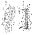
- FIG. 1 to 7 illustrate in schematic form the main steps for manufacturing a breathable and waterproof sole for a shoe according to the invention, which is shown in Fig. 8 and Fig. 9 after completion of processing, denoted by 100, as well the subsequent manufacture of a shoe (shown only partially) with such a sole.
- steps indicated by a1-a9, are as follows:
- the user's foot rests, preferably also by means of an inner sole (not shown), on the membrane 117.
- Any outer water, with which the sole 100 of the shoe comes into contact, is stopped by the membrane 117 and by the felt 102a, which may at the most become soaked superficially (namely a few millimetres).
- the felt 102a In order to avoid also this minimum absorption it is possible to use felt covered by polyurethane film.
- the sole structure according to the invention produces a very advantageous effect. Since the membrane 117 is situated above a support which has at least one region 107 in communication with the exterior (namely downwards through the openings 113) and is joined to said support layer at least along a contour which surrounds said region (the rim 115 in the example described), the membrane 117 is not constrained - as in the sandwich structures according to the prior art - such that it adheres to the breathable layer 107. Therefore, the movement of the foot favours a vertical oscillation of the membrane 117, which is also favoured by an air chamber 140 which is created between the latter and the breathable layer 107 (see Fig. 9 ), and this causes pumping of the air out from the sole 100 of the shoe.
- This air conveys outside the moisture present inside the shoe and produced for example by sweating of the foot. Obviously this moist air pumping action significantly improves the comfort of the shoe with the sole 100 compared to conventional shoes. It is also possible to insert inside the chamber 140 a cushion of spongy material (for example expanded polyurethane with large open pores) which favours the pumping action.
- a cushion of spongy material for example expanded polyurethane with large open pores
- the membrane 117 is applied to the insole 101 after overinjection of the element 111 has been performed and therefore is not subject to the risk of deterioration caused by the high temperature during the injection step.
- the local application of the tape 121 onto the edge of the membrane 117 is a process which does not involve any risk of damaging the membrane 117, since the tape is compatible with the said membrane 117.
- Maximum insulation against water penetration is achieved as well as a certain elasticity between the membrane 117 and the rim 115 which, in the case where the chamber 140 is occupied by a breathable cushion (not shown) in order to improve the comfort, ensures a slight degree of yielding along the perimeter of the membrane 117 which does not risk tearing.
- Figures 10 to 15 show the main steps for the manufacture of a second sole according to the invention which is shown in Fig. 16 and Fig. 17 after completion of processing, denoted by 200, as well the subsequent manufacture of a shoe (shown only partially) with such a sole. These steps, indicated by b1-b10, are as follows:
- the user's foot rests, preferably also by means of an inner sole (not shown), on the part 290 of the stocking 260 made of membrane material.
- the penetration of water from outside the shoe with a sole 200 is stopped by the membrane of the part 290 and the glue 295.
- the structure of the sole 200 according to the invention produces the effect of pumping the moist air outside the shoe, as already described with reference to the membrane 117, owing to the fact that the membrane in the part 290 is not attached to the fabric 207 and is able to oscillate inside an air chamber 288 above said layer of fabric 207.
- the impermeable and breathable membrane is applied to the insole 201 after overinjection of the element 211 has been performed and therefore does not risk being damaged by the high temperature during the injection step.
- the various gluing steps may be performed by means of spot gluing (spiderweb technique) or spray gluing, so as to reduce to a minimum the risk of damaging the membrane.
- Figures 18 to 22 show the main steps for the manufacture of a third sole according to the invention which is shown in Fig. 23 and Fig. 24 after completion of processing, denoted by 300, as well the subsequent manufacture of a shoe (shown only partially) with such a sole. These steps, indicated by c1-c8, are as follows:
- the user's foot rests, preferably by means of an inner sole, on the part 390 of the stocking 360 consisting of the membrane.
- the penetration of water from outside the shoe with a sole 300 is stopped by the stocking 360 in the membrane part 390 and by the glue 395.
- the impermeable and breathable membrane is applied to the insole 301 after overinjection of the element 311 has been performed and therefore does not risk being damaged by the high temperature during injection.
- the various gluing steps may be performed by means of spot gluing (spiderweb technique) or spray gluing, so as to reduce to a minimum the risk of damaging the membrane.
- the membrane in the part 390 does not risk tearing with the movements of the foot.
- it since it may be stitched and/or glued without being tensioned, it may be subject to deformations resulting from movement of the foot without critical stresses.
- the protective element 111, 211, 311 may be made of very strong material (necessary, among other things, for protecting the membrane 117, 290, 390), while the tread sole 129, 212, 312 may be very soft (in order to dampen the shocks): the comfort of the shoe according to the invention is significantly improved.
- the protective element 111, 211, 311 it is possible to choose to form the protective element 111, 211, 311 as an additional tread portion in contact with the ground or design it with dimensions such that it does not touch the ground.
- the form of the sole 129, 212, 312 may comprise a recess zone 199, 299, 399 such as that which surrounds laterally most of the perforated element 111, 211, 311 or a hole inside which a complementary perforated element such as those indicated by 111, 211, 311 is seated.
- the perforated element 111, 211, 311 may comprise openings 113, 213, 313 of varying shape and orientation provided that they allow the moist air from inside the shoe to reach the outside of said shoe. Obviously, it is possible to provide one or more perforated elements 111, 211, 311 which are identical or different, situated closely alongside each other or very spaced.
- a soft breathable element inside the volume 140, 288, 388 in order to increase the comfort of the foot.
- said element must be made of a porous or meshwork material so as not to reduce the flow of moist air leaving the sole.
- the membrane 207 or the membrane stocking 260, 360 it is possible to use those which are commercially available and which are usually present in the form of a multi-layered sandwich so that they are stronger.
- the membrane according to the invention may be arranged over the at least one region which allows the air to pass through, simply resting thereon (i.e. loosely) or slightly tensioned, sufficient, for example, for it not to be creased.
- the support layer comprises a region having a material which allows the air to pass through, said material by protecting said region and/or the membrane improving the reliability and the strength of the sole (and the shoe), variations of the invention where said material is absent are possible.
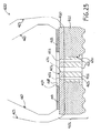
- FIG. 25 shows in schematic form a cross-sectional view of a fourth finished sole 400 according to the invention which does not comprise said air-permeable material.
- the sole 400 comprises a support layer 401 consisting of the combination of an inner sole 410 and a tread 412.
- the inner sole 410 has a region 403 which allows the passage of the air, in particular through through-channels 453. Said channels emerge on one side inside a hole 450 in the tread 412 and on the other side in an air chamber 488.
- Said chamber 488 is delimited by a tubular stocking 460 of membrane material 417, contained in an upper 423, and by some glue 415 which seals the stocking 460 on the support layer 401.
- a reinforcing element 411 (for the tread and/or for the region 403) is inserted inside the hole 450 of the tread 412, said element having through-holes 413 for evacuating the air from inside the shoe 460 which passes through the membrane 417 and the holes 453 of the region 403.
- the pumping effect described above is also present in this fourth sole 400 which may be subject to all the constructional variants already described above.
- the sole 400 may also be provided with a water-proof material which allows the passage of the air, in particular for protection of the membrane 417.
- a meshwork fabric or a membrane made of a material which is waterproof and vapour-permeable could, for example, be arranged above or underneath the region 403, so as to cover its holes 453, or in the middle of the said region 403, using a technique such as that described for the third sole 300.
- the reinforcing element 411 must not necessarily extend over the whole thickness of the tread 412, an initial portion extending from the region 403 or from the surface of the tread 412 in contact with the ground being sufficient, for example.
Description
- The present invention relates to a shoe with a breathable sole.
- It is known that, in order to ensure hygienic and comfortable conditions for the feet, a shoe should not trap the products of perspiration (moisture and water vapour) but, on the contrary, should prevent stagnation thereof. This requirement is all the greater if the foot is subject to overheating or to stresses (for example sporting activities). Obviously the strength and the protection provided by the shoe must not be compromised in the attempt to make a shoe breathable.
- Many solutions which aim to obtain a shoe which is both breathable as well as comfortable and safe are known. Patent application
WO 04/028284 - a support layer which in at least one macro-portion is made of "perforated" material;
- a breathable membrane associated on top of the support layer at least in the macro-portion;
- a tread made of plastic material with a macro-perforation at least at the macro-portion, the tread being joined hermetically to the membrane and to the support layer at least along the perimeter of the macro-portion.
- The patent application
WO 02/32246 - In patent application
WO 98/51177 - In patent
EP 1,089,642 the technical problem is that of increasing the circulation (otherwise poor) of air inside the shoes, while protecting the breathable membrane which renders the shoe breathable. It is considered that the poor circulation is due to the small number of perforations in the shoe with respect to its surface area, so that the solution proposed is a sole with an integrated tread in which raised vertical projections in an empty region are in contact with a protective layer on top of which a membrane is associated. The empty region communicates with the exterior of the shoe via numerous horizontal channels. - In the patent application
WO 02/14326 - All these solutions have intrinsic disadvantages. The sandwich structure which includes the breathable membrane is commonly fixed to the remainder of the shoe by means of overinjection of plastic material which forms the tread. There is therefore the risk of damaging the membrane which per se is very delicate and does not withstand very well the aggressive action of the melted plastic material. Another very important disadvantage is that the expulsion of the moisture from inside the shoe through the membrane may take place only naturally, namely that the moisture must pass through the membrane spontaneously. This is a very slow natural process; a forced process which increases the efficiency thereof would be advantageous.
Also known isUS 2001/0010127 , wherein there is disclosed a sole with a breathable membrane laid on a support layer which is perforated in a region under the membrane and is reinforced by vertical hollow inserts. The membrane rests at the same level of the sole and is disclosed as strictly tensioned. - The object of the present invention is to provide a shoe with a breathable sole devoid of the problems and drawbacks mentioned above briefly.
- This object is achieved with a sole for a waterproof and breathable shoe having the features claimed in Claim 1.
- As will be clarified more fully below, a sole according to the invention has mainly these advantages:
- the waterproof membrane is sealed onto sole elements after joining of the reinforcing elements (preferably by means of overinjection) has been performed; all the problems resulting from the high temperature of the melted material and/or those associated with handling of the membrane are therefore eliminated; obtained even if the membrane is not raised from the edge of the said region (namely with smaller dimensions of the air chamber), but only extends over it in an untensioned state; in this case a movement of the foot is sufficient to cause oscillation of the membrane and create the pumping effect.
- A support element is understood generally as being a membrane support element which may be in contact with the ground and may therefore also be stratified or comprise various sub-elements, such as a mounting insole, a tread sole or the two together.
- The membrane, which is sealed on the support layer, is advantageously sealed on said support layer at least along a contour outside said region. This allows either an increase in the dimensions of the air chamber or in any case an increase in the amount of movement which the membrane is able to perform, since its unconstrained surface area increases. In some case, for constructional reasons, it is possible to fix the membrane at certain points along said region (for example in shoes used in extreme activities, where the foot movements are considerable and the membrane could perform uncontrollable oscillating movements). Even though the mobility of the membrane is limited in this case, every free portion thereof nevertheless acts as a pumping surface.
- The reinforcing elements strengthen either the said region through which the air is able to pass or the overall structure of the sole, or both.
- The said region which allows the passage of the air through said support layer may have channels for allowing the air to pass through. Said region may also have, advantageously associated with it, a material which allows the passage of the air, for example a meshwork fabric or a membrane made of a material which is waterproof and vapour-permeable. In this way the water tightness and the robustness (and strength) of the sole is advantageously improved.
- The advantages of the invention will emerge more clearly from the following description of a preferred embodiment of the invention, provided by way of example and with reference to the accompanying drawings, in which:
-
Figures 1 to 7 illustrate the steps for manufacturing a first embodiment of the sole and therefore the shoe according to the invention; -
Figure 8 shows a plan view, from below, of the finished sole according toFig. 1 ; -
Figure 9 shows a cross-sectional view along the plane I-I of the sole according toFig. 8 and part of the associated shoe; -
Figures 10 to 15 illustrate the steps for manufacturing a second embodiment of the sole and therefore the shoe according to the invention; -
Figure 16 shows a plan view from below of the second sole finished; -
Figure 17 shows a cross-sectional view along the plane II-II of the sole according toFig. 16 and of part of the associated shoe; -
Figures 18 and22 illustrate the steps for manufacturing a third embodiment of the sole according to the invention; -
Figure 23 shows a plan view, from below, of the third sole finished; -
Figure 24 shows a cross-sectional view along the plane III-III of the sole according toFig. 23 and of part of the associated shoe; -
Figure 25 shows in schematic form a cross-sectional view along a plane vertical and perpendicular to the length of the foot of a fourth finished sole according to the invention. -
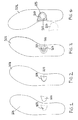
Figures 1 to 7 illustrate in schematic form the main steps for manufacturing a breathable and waterproof sole for a shoe according to the invention, which is shown inFig. 8 and Fig. 9 after completion of processing, denoted by 100, as well the subsequent manufacture of a shoe (shown only partially) with such a sole. These steps, indicated by a1-a9, are as follows: - a1) a mounting insole 101 (see
Fig. 1 and alsoFig. 9 ) is composed of a sandwich consisting of a first water-repellent material 102a (e.g. ordinary felt which does not "draw" the water), an aluminium film 102b and a second layer of water-repellent material 102a (identical to the first layer).The (optional) aluminium layer 102b is useful for preserving heat and acting as an insulator; theinsole 101 could, for example, consist of a single layer of felt; theinsole 101 moreover has, formed therein, at least one central window (or through-opening) 103 for example formed by means of punching; - a2) a
permeable fabric 107, for example a meshwork fabric, with dimensions corresponding to or also greater than those of the window is fixed, preferably by means of aperimetral stitch 105, in thewindow 103 of the insole 101 (seeFig. 2 ); - a3) an overinjection of thermoplastic material is performed onto the meshwork fabric 107 (see
Fig. 3 ) on the side facing the ground, in order to form a perforated reinforcingelement 111 having at least one, but preferably several holes or vertical openings 113 (only some are indicated by the reference number for the sake of simplicity); saidholes 113 let thefabric 107 communicate with the exterior; theelement 111 has greater dimensions than the surface of themeshwork fabric 107 and passes through its entire thickness, covering and sealing also thestitching 105; - a4) a second overinjection of thermoplastic material is performed (
Fig. 4 ) in the part of the mounting insole opposite theelement 111, i.e. that facing the foot, so as to obtain a rim (or frame) 115 which surrounds saidmeshwork fabric 107; - a5) a portion of the
membrane 117 made of material which is waterproof and vapour-permeable is cut out, said membrane having an extension equal to or greater than therim 115 5 and being fixed thereto by means of a perimetral stitching 119 (Fig. 5 ); - a6) the
stitching 119 is covered (Fig. 6 ) with aspecial tape 121 compatible with theunderlying rim 115 by means of heat-welding or high-frequency welding; the tape is welded perfectly to the edge of themembrane 117, without damaging it, and to therim 115, joining them together with a waterproof seal; - a7) the
insole 101 thus manufactured is applied to an upper 123 (seeFig. 9 ) by means of a perimetral stitch 125 (which can be seen inFig. 7 ); - a8) a covering
element 127, formed by means of injection inside a separate mould, is applied onto theinsole 101 so as to cover/protect at least a part of theperimetral stitching 125; - a9) a
tread sole 129 is applied to theinsole 101, using glues or by means of direct injection onto the upper; the sole 129 comprises anrecess zone 199 which surrounds partly theelement 111. - The user's foot rests, preferably also by means of an inner sole (not shown), on the
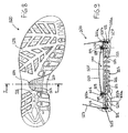
membrane 117. Any outer water, with which the sole 100 of the shoe comes into contact, is stopped by themembrane 117 and by the felt 102a, which may at the most become soaked superficially (namely a few millimetres). In order to avoid also this minimum absorption it is possible to use felt covered by polyurethane film. - It should be noted how the sole structure according to the invention produces a very advantageous effect. Since the
membrane 117 is situated above a support which has at least oneregion 107 in communication with the exterior (namely downwards through the openings 113) and is joined to said support layer at least along a contour which surrounds said region (therim 115 in the example described), themembrane 117 is not constrained - as in the sandwich structures according to the prior art - such that it adheres to thebreathable layer 107. Therefore, the movement of the foot favours a vertical oscillation of themembrane 117, which is also favoured by anair chamber 140 which is created between the latter and the breathable layer 107 (seeFig. 9 ), and this causes pumping of the air out from the sole 100 of the shoe. This air conveys outside the moisture present inside the shoe and produced for example by sweating of the foot. Obviously this moist air pumping action significantly improves the comfort of the shoe with the sole 100 compared to conventional shoes. It is also possible to insert inside the chamber 140 a cushion of spongy material (for example expanded polyurethane with large open pores) which favours the pumping action. - The
membrane 117 is applied to theinsole 101 after overinjection of theelement 111 has been performed and therefore is not subject to the risk of deterioration caused by the high temperature during the injection step. The local application of thetape 121 onto the edge of themembrane 117 is a process which does not involve any risk of damaging themembrane 117, since the tape is compatible with the saidmembrane 117. Maximum insulation against water penetration is achieved as well as a certain elasticity between themembrane 117 and therim 115 which, in the case where thechamber 140 is occupied by a breathable cushion (not shown) in order to improve the comfort, ensures a slight degree of yielding along the perimeter of themembrane 117 which does not risk tearing. -
Figures 10 to 15 show the main steps for the manufacture of a second sole according to the invention which is shown inFig. 16 and Fig. 17 after completion of processing, denoted by 200, as well the subsequent manufacture of a shoe (shown only partially) with such a sole. These steps, indicated by b1-b10, are as follows: - b1) a mounting insole 201 (see
Fig. 11 and alsoFig. 17 ) is composed of a sandwich consisting of a first water-repellent material 202a (e.g. ordinary felt which does not "draw" the water), analuminium film 202b and a second layer of water-repellent material 202a (identical to the first layer); the same comments made for thelayers 102a and 102b are applicable for thelayer insole 201 has, moreover, formed therein, at least one central window (or opening) 203 for example formed by means of punching; - b2) a water and air
permeable fabric 207, for example a meshwork fabric, with corresponding or also slightly greater dimensions is fixed, by means of a perimetral stitch 205 (or other system, for example by high-frequency welding), at thewindow 203 of the insole 201 (seeFig. 12 ); - b3) an overinjection of thermoplastic material is performed onto the meshwork fabric 207 (see
Fig. 13 ) on the side facing the ground, in order to form a perforated reinforcingelement 211 having at least one and preferably several holes or vertical openings 213 (only some are indicated by the reference number for the sake of simplicity); saidholes 213 connect thefabric 207 to the exterior; theelement 211 has greater dimensions than the surface of themeshwork fabric 207 and passes through its entire thickness, covering and sealing also thestitching 205; - b4) a second overinjection of thermoplastic material is performed (
Fig. 14 ) in the part of the mountinginsole 201 opposite theelement 211, i.e. that part facing the foot, so as to obtain a rim (or frame) 215 which surrounds saidmeshwork fabric 207; - b5) the
insole 201 thus formed is applied to an upper 250 by means of a perimetral stitching 266 (seeFig. 17 ); - b6) a
tubular stocking 260 is prepared (seeFig. 10 ) using an impermeable and breathable membrane having characteristics identical to those of themembrane 107; the stocking 260 comprises anupper part 289 enveloping the upper part of the foot and asecond insole part 290; the twoparts stitches 292 which are then heat-welded in order to prevent water infiltration; - b7) the
surface 294 of the mountinginsole 201 facing the foot is covered withglue 295, except for the area comprised by the element 215 (seeFig. 14 andFig. 17 ); - b8) the bottom zone of the
tubular stocking 260 in the region of theinsole 290 is covered with glue, except for the area indicated by 271 inFig. 10 (shown in broken lines), said area corresponding substantially to the area delimited by theelement 215 on theinsole 201; the stocking 260 and theinsole 201 are then glued together; - b9) the
tubular stocking 260 consisting of the membrane is applied to the upper 250 by means a perimetral stitching (not shown) in the zone of the collar; - b10) an
element 227 made of plastic material, obtained by means of injection in a separate mould, is applied onto theinsole 201 so as to cover/protect at least a part of theperimetral stitching 266 and atread sole 212 is applied; the sole 212 comprises arecess zone 299 which surrounds partially theelement 111. - As in the preceding variant, the user's foot rests, preferably also by means of an inner sole (not shown), on the
part 290 of the stocking 260 made of membrane material. The penetration of water from outside the shoe with a sole 200 is stopped by the membrane of thepart 290 and theglue 295. - It should be noted how the structure of the sole 200 according to the invention produces the effect of pumping the moist air outside the shoe, as already described with reference to the
membrane 117, owing to the fact that the membrane in thepart 290 is not attached to thefabric 207 and is able to oscillate inside anair chamber 288 above said layer offabric 207. - Moreover, the impermeable and breathable membrane is applied to the
insole 201 after overinjection of theelement 211 has been performed and therefore does not risk being damaged by the high temperature during the injection step. The various gluing steps may be performed by means of spot gluing (spiderweb technique) or spray gluing, so as to reduce to a minimum the risk of damaging the membrane. -
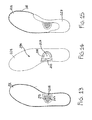
Figures 18 to 22 show the main steps for the manufacture of a third sole according to the invention which is shown inFig. 23 and Fig. 24 after completion of processing, denoted by 300, as well the subsequent manufacture of a shoe (shown only partially) with such a sole. These steps, indicated by c1-c8, are as follows: - c1) a mounting insole 301 (see
Fig. 18 ) is obtained by injectingthermoplastic material 302 over ameshwork fabric 307, using a method which the Applicant has described in European patentEP 697,957 insole 301 overinjection is not performed in at least one central window (or opening) 303; in this way, in the region where overinjection has not been performed, theunderlying meshwork fabric 307 is left exposed (a solution involving the formation of a region comprising several small holes or a grid is also possible, for example); clearly it is possible to provide more than one window also with different shapes; - c2) an overinjection of thermoplastic material is performed in the exposed zone of meshwork fabric 307 (see
Fig. 19 ) on the side of theinsole 301 facing the ground, so as to form a perforated reinforcingelement 311 having at least one and preferably several holes or vertical openings 313 (only some are indicated by the reference number for the sake of simplicity); saidholes 313 let thefabric 207 communicate with the exterior; theelement 311 has greater dimensions than thewindow 303 ofmeshwork fabric 307 and passes through its entire thickness; - c3) in the part of the mounting
insole 301 opposite theelement 311, i.e. that part facing the foot, areference groove 305 which surrounds saidwindow 303 ofmeshwork fabric 307 is formed (seeFig. 21 and24 ); - c4) the surface of the mounting
insole 301 facing the foot is covered withglue 395, except for the area delimited by thegroove 305; - c5) a
tubular stocking 360 is prepared (seeFig. 20 ) using an impermeable and breathable membrane having characteristics identical to those of themembrane 107; the stocking 360 comprises anupper part 389 enveloping the upper part of the foot and asecond insole part 390; the twoparts stitches 392 which are then heat-welded in order to prevent water infiltration; - c6) the bottom surface of the
tubular stocking 360 in the zone of theinsole 390 is covered withglue 395, except for the area indicated by 371 inFig. 20 (shown in broken lines), this area corresponding substantially to the area delimited by thegroove 305 on theinsole 301; the stocking 360 and theinsole 301 are then glued together; - c7) the
tubular stocking 360 made of impermeable and breathable material is applied to an upper 350 (seeFig. 24 ) by means of a perimetral stitching (not shown) in the zone of the collar, while thebottom edges 351 of the upper 350 are folded over and glued underneath theinsole 301; - c8) a reinforcing
element 327 obtained by means of injection in a separate mould is applied onto theinsole 301 so as to cover/protect at least a part of theedges 351 and a tread sole 312, which comprises arecess zone 399 which surrounds partially theelement 111, is applied. - As in the preceding variant, the user's foot rests, preferably by means of an inner sole, on the
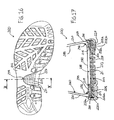
part 390 of the stocking 360 consisting of the membrane. The penetration of water from outside the shoe with a sole 300 is stopped by the stocking 360 in themembrane part 390 and by theglue 395. - It should be noted again how the structure according to the invention in the shoe with sole 300 produces the effect of pumping the moist air outside the sole 300, as already described with reference to the
membrane 117, owing to the fact that themembrane part 390 is not attached to thefabric 307 and may oscillate inside anair chamber 388 above said layer offabric 307. - Moreover, the impermeable and breathable membrane is applied to the
insole 301 after overinjection of theelement 311 has been performed and therefore does not risk being damaged by the high temperature during injection. The various gluing steps may be performed by means of spot gluing (spiderweb technique) or spray gluing, so as to reduce to a minimum the risk of damaging the membrane. - Another advantage (present moreover in all three variants described) is that the membrane in the
part 390 does not risk tearing with the movements of the foot. In fact, since it may be stitched and/or glued without being tensioned, it may be subject to deformations resulting from movement of the foot without critical stresses. - The
protective element membrane tread sole protective element - Manufacture of the sole according to the invention does not involve particular constructional problems and avoids complicated shapes of the sole, as in
EP 1,089,642 , which adversely affect the cost and simplicity of production. - The form of the sole 129, 212, 312 may comprise a
recess zone perforated element - The
perforated element openings perforated elements - It is possible to insert a soft breathable element inside the
volume - For the
membrane 207 or themembrane stocking - Even though, in the three embodiments described, the support layer comprises a region having a material which allows the air to pass through, said material by protecting said region and/or the membrane improving the reliability and the strength of the sole (and the shoe), variations of the invention where said material is absent are possible.
- With reference to
Fig. 25 , this shows in schematic form a cross-sectional view of a fourth finished sole 400 according to the invention which does not comprise said air-permeable material. The sole 400 comprises asupport layer 401 consisting of the combination of an inner sole 410 and atread 412. The inner sole 410 has aregion 403 which allows the passage of the air, in particular through through-channels 453. Said channels emerge on one side inside ahole 450 in thetread 412 and on the other side in anair chamber 488. Saidchamber 488 is delimited by atubular stocking 460 ofmembrane material 417, contained in an upper 423, and by someglue 415 which seals the stocking 460 on thesupport layer 401. All the comments made in connection with similar elements in the preceding embodiments are applicable to thestocking 460, themembrane 417 and sealing thereof, and are not repeated here. A reinforcing element 411 (for the tread and/or for the region 403) is inserted inside thehole 450 of thetread 412, said element having through-holes 413 for evacuating the air from inside theshoe 460 which passes through themembrane 417 and theholes 453 of theregion 403. The pumping effect described above is also present in this fourth sole 400 which may be subject to all the constructional variants already described above. Obviously the sole 400 may also be provided with a water-proof material which allows the passage of the air, in particular for protection of themembrane 417. For this material it is possible to choose, for example, a meshwork fabric or a membrane made of a material which is waterproof and vapour-permeable. A layer of this material could, for example, be arranged above or underneath theregion 403, so as to cover itsholes 453, or in the middle of the saidregion 403, using a technique such as that described for the third sole 300. The reinforcingelement 411 must not necessarily extend over the whole thickness of thetread 412, an initial portion extending from theregion 403 or from the surface of thetread 412 in contact with the ground being sufficient, for example.
Claims (20)
- Sole (100; 200; 300; 400) for an impermeable and breathable shoe having a structure comprising a support layer (101; 201; 301; 401) having at least one region (103; 203; 303; 403) which allows the passage of air through said support layer (101; 201; 301; 401), said sole further comprising:- one or more reinforcing elements (111; 211, 311; 411) joined to one side of said support layer (101; 201; 301; 401) at said at least one region (103; 203; 303, 403) and perforated with through-openings (113; 213; 313; 413) for evacuating the air which passes through said region;- a membrane (117; 290, 390; 417) made of material which is waterproof and vapour-permeable, situated above said at least one region (103; 203; 303, 403) on the side of said support layer (101; 201; 301, 401) opposite said reinforcing element (111; 211, 311; 411),characterized in that
said membrane is sealed on said support layer (101; 201; 301; 401) at least along one contour (115; 215; 305) around said at least one region (103; 203; 303; 403 end rests untensioned on said region (103; 203; 303) sufficiently in order to delimit above said at least one region (103; 203; 303; 403) an air chamber (140; 288; 388; 488) and in order to have at least one free oscillating portion acting as a pumping surface by a movement of the foot, the resulting compression and expansion of the air chamber being able to produce an airflow which passes through said at least one region (103; 203; 303; 403) and the openings (113; 213; 313; 413) of said one or more reinforcing elements (111; 211, 311; 411). - Sole (100; 200; 300; 400) according to Claims 1, wherein said membrane (117; 290, 390; 417) is joined to the support layer (101; 201; 301; 401) along said contour (115; 215; 305) by means of a spacing element (115; 215; 395; 415).
- Sole (100; 200) according to Claim 2, wherein said spacing element is a rim (15; 215) which is applied onto the support layer (101; 201) along a contour around said at least one region (103; 203) and on the edges of which said membrane (117; 290) is sealed.
- Sole (100; 200; 300) according to any one of the preceding Claims, wherein a soft breathable element is housed inside said air chamber (140; 288; 380).
- Sole (100) according to any one of the proceeding claims, in which said support layer (101; 201; 301) comprises an insole (101; 201) made of water-repellent material (102a, 202a).
- Sole (100) according to Claim 5, wherein said insole (101; 201) comprises a through-opening (103; 203) onto the edges of which a permeable and breathable fabric (107; 207) is joined.
- Sole (300) according to any one of Claims 1 to 4, wherein said support layer comprises an insole (301) obtained by injecting thermoplastic material (302) on top of a meshwork fabric (307) leaving at least one region (303) of meshwork fabric (307) exposed.
- Sole (300) according to any one of Claims 2 to 7, wherein said spacing element is a layer of glue (395).
- Sole (200; 300; 400) according to any one of Claims 3 to 8, wherein said membrane (290, 390; 417) forms a tubular stocking (260; 360; 460) for receiving the foot, sealed by an insole part (290; 390) with said support layer (201; 301; 401) at least along a contour around said region (203; 303; 403).
- Sole (200) according to Claim 9 wherein said insole part (290) is sealed with said support layer (201) at least along the edge of said rim (215).
- Sole (300; 400) according to Claim 9, wherein said insole part (390) is sealed with said support layer (301; 401) using glue (395; 415) arranged at least along a contour (305) around said region (303; 403).
- Sole (300) according to Claim 11, wherein a groove (305) on the surface of said support layer confines said glue (395) on the outside of a contour around said region (303).
- Sole (100; 200; 300; 400) according to any one of the proceeding claims, wherein said support layer (101; 201; 301) comprises a tread sole (129; 212; 312; 412) having a recess zone (199; 299; 399) which surrounds laterally said one or more perforated elements (111; 211; 311).
- Sole (100; 200; 300; 400) according to any one of the preceding claims, wherein said support layer (101; 201; 301; 401) comprises a tread sole (129; 212; 312; 412) having a hole inside which said one or more perforated elements (111; 211, 311; 411) are housed.
- Sole (100; 200; 300; 400) according to any one of the preceding claims, wherein said contour (115; 215; 305) is a contour outside said region (103; 203; 303; 403).
- Sole (100; 200; 300; 400) according to any one of the preceding claims, wherein said region (103; 203; 303; 403) is protected by a layer of material which allows the passage of air through said region.
- Sole (100; 200; 300; 400) according to Claim 16, wherein said layer of material which allows the passage of air covers said region (103; 203; 303; 403).
- Sole (100; 200; 300; 400) according to Claim 17, in which said layer of material which allows the passage of air comprises a meshwork fabric.
- Sole (100; 200; 300; 400) according to Claim 16 or 17, wherein said layer of material which allows the passage of air comprises a membrane made of material which is waterproof and vapour-permeable.
- Shoe comprising a sole (100; 200; 300; 440) according to any one of the preceding claims.
Priority Applications (2)
| Application Number | Priority Date | Filing Date | Title |
|---|---|---|---|
| PL06763461T PL1830673T3 (en) | 2005-06-15 | 2006-06-01 | Shoe with breathable sole |
| SI200630114T SI1830673T1 (en) | 2005-06-15 | 2006-06-01 | Shoe with breathable sole |
Applications Claiming Priority (2)
| Application Number | Priority Date | Filing Date | Title |
|---|---|---|---|
| IT000084A ITTV20050084A1 (en) | 2005-06-15 | 2005-06-15 | FOOTWEAR WITH BREATHABLE SOLE. |
| PCT/EP2006/062839 WO2006134033A1 (en) | 2005-06-15 | 2006-06-01 | Shoe with breathable sole |
Publications (2)
| Publication Number | Publication Date |
|---|---|
| EP1830673A1 EP1830673A1 (en) | 2007-09-12 |
| EP1830673B1 true EP1830673B1 (en) | 2008-10-08 |
Family
ID=36660167
Family Applications (1)
| Application Number | Title | Priority Date | Filing Date |
|---|---|---|---|
| EP06763461A Active EP1830673B1 (en) | 2005-06-15 | 2006-06-01 | Shoe with breathable sole |
Country Status (20)
| Country | Link |
|---|---|
| US (1) | US8732985B2 (en) |
| EP (1) | EP1830673B1 (en) |
| JP (1) | JP5145216B2 (en) |
| AR (1) | AR055582A1 (en) |
| AT (1) | ATE410090T1 (en) |
| CA (1) | CA2612276C (en) |
| DE (1) | DE602006003062D1 (en) |
| DK (1) | DK1830673T3 (en) |
| ES (1) | ES2316086T3 (en) |
| HK (1) | HK1113648A1 (en) |
| HR (1) | HRP20080571T3 (en) |
| IT (1) | ITTV20050084A1 (en) |
| NO (1) | NO20080192L (en) |
| PL (1) | PL1830673T3 (en) |
| PT (1) | PT1830673E (en) |
| RS (1) | RS50705B (en) |
| RU (1) | RU2401623C2 (en) |
| SI (1) | SI1830673T1 (en) |
| UA (1) | UA90149C2 (en) |
| WO (1) | WO2006134033A1 (en) |
Families Citing this family (17)
| Publication number | Priority date | Publication date | Assignee | Title |
|---|---|---|---|---|
| ITTV20050084A1 (en) | 2005-06-15 | 2006-12-16 | Asolo Spa | FOOTWEAR WITH BREATHABLE SOLE. |
| CN101448420B (en) * | 2006-05-29 | 2012-09-05 | 健乐士股份公司 | Ventilated waterproof sole, shoes using the sole, and manufacturing method of the sole and shoes |
| JP2013022182A (en) * | 2011-07-20 | 2013-02-04 | Hongkong Madam:Kk | Boot |
| DE102012206094B4 (en) | 2012-04-13 | 2019-12-05 | Adidas Ag | Soles for sports footwear, shoes and method of making a shoe sole |
| RU2521313C2 (en) * | 2012-10-16 | 2014-06-27 | Сергей Сергеевич Терехов | Water-proof ventilated footwear sole |
| DE102013202291B4 (en) * | 2013-02-13 | 2020-06-18 | Adidas Ag | Damping element for sportswear and shoes with such a damping element |
| USD776410S1 (en) | 2013-04-12 | 2017-01-17 | Adidas Ag | Shoe |
| US9789644B2 (en) * | 2014-11-13 | 2017-10-17 | Adidas Ag | Methods of vacuum forming articles of wear |
| JP6679363B2 (en) | 2015-03-23 | 2020-04-15 | アディダス アーゲー | Soles and shoes |
| DE102015206486B4 (en) | 2015-04-10 | 2023-06-01 | Adidas Ag | Shoe, in particular sports shoe, and method for manufacturing the same |
| DE102015206900B4 (en) | 2015-04-16 | 2023-07-27 | Adidas Ag | sports shoe |
| DE102015209795B4 (en) | 2015-05-28 | 2024-03-21 | Adidas Ag | Ball and process for its production |
| US11350701B2 (en) | 2015-10-09 | 2022-06-07 | Adidas Ag | Laceless shoe |
| DE102015219636B4 (en) | 2015-10-09 | 2023-11-23 | Adidas Ag | Manufacturing process for coating a fabric with a three-dimensional shape |
| US11758979B2 (en) | 2015-10-09 | 2023-09-19 | Adidas Ag | Shoe |
| US11297902B2 (en) | 2016-10-03 | 2022-04-12 | Adidas Ag | Laceless shoe |
| USD894565S1 (en) * | 2019-02-01 | 2020-09-01 | Maincal S.A. | Sole for safety shoe |
Family Cites Families (33)
| Publication number | Priority date | Publication date | Assignee | Title |
|---|---|---|---|---|
| GB149616A (en) | 1919-08-06 | 1921-10-26 | Georges Ernest Camille Gerber | Shoe with pneumatic sole |
| JPS54116427U (en) * | 1978-02-03 | 1979-08-15 | ||
| JPS5712002U (en) * | 1980-06-19 | 1982-01-21 | ||
| GB2114425B (en) | 1982-02-05 | 1985-05-30 | Clarks Ltd | Sole units for footwear |
| AU560435B2 (en) * | 1982-09-09 | 1987-04-09 | Patine Shokai, K.K. | Boot |
| ITPD20020246A1 (en) * | 2002-09-24 | 2004-03-25 | Geox Spa | STRUCTURE OF WATERPROOF AND BREATHABLE SOLE FOR FOOTWEAR AND FOOTWEAR MADE WITH THE SOLE. |
| JPH033201U (en) * | 1989-06-01 | 1991-01-14 | ||
| ES1019098Y (en) | 1991-02-13 | 1992-10-01 | Perez Clemente Joaquin | CHAMBER OF AERATION AND AMORTIZATION FOR FOOTWEAR. |
| GB2264626B (en) | 1992-02-21 | 1995-10-04 | Tecnic Shoe Co Ltd The | Footwear |
| ATE157509T1 (en) | 1992-05-23 | 1997-09-15 | Armenak Moumdjian | SHOE WITH A SOLE PROVIDED WITH AN INFLATABLE, REMOVABLE BELLOW |
| JPH06245803A (en) * | 1993-02-22 | 1994-09-06 | Achilles Corp | Shoe with permeable sole and its manufacturing method |
| IT1274340B (en) | 1994-03-09 | 1997-07-17 | Nordica Spa | PROCEDURE FOR THE REALIZATION OF FOOTWEAR BY INJECTION OF PLASTIC MARERIAL AND FOOTWEAR OBTAINED BY THAT PROCEDURE |
| JP3023584U (en) * | 1995-10-06 | 1996-04-23 | モリト株式会社 | Ventilation sole |
| JP3280595B2 (en) * | 1997-02-13 | 2002-05-13 | 杉浦 慶典 | Shoes and manufacturing method thereof |
| IT1293474B1 (en) | 1997-05-09 | 1999-03-01 | Nottington Holding Bv | PERFECTED BREATHABLE FOOTWEAR |
| IT1296238B1 (en) * | 1997-10-21 | 1999-06-18 | Nottington Holding Bv | BREATHABLE FOOTWEAR WITH IMPROVED BREATHING ACTION |
| ITPD980157A1 (en) | 1998-06-25 | 1999-12-25 | Nottington Holding Bv | BREATHABLE AND WATERPROOF SOLE FOR FOOTWEAR |
| DE60019721T2 (en) * | 1999-09-21 | 2005-09-29 | Geox S.P.A., Montebelluna-Localita Biadene | WATERPROOF AND MOISTURIZING SHOE AND METHOD OF ITS MANUFACTURE |
| ITPD20000027A1 (en) * | 2000-01-31 | 2001-07-31 | Nottington Holding Bv | WATERPROOF AND BREATHABLE SOLE PERFECTED FOR FOOTWEAR |
| EP1127505B1 (en) | 2000-02-28 | 2004-08-11 | STONEFLY S.p.A. | Forced air circulation shoe structure |
| DE10036100C1 (en) * | 2000-07-25 | 2002-02-14 | Adidas Int Bv | Sports shoe has inner sole layer with openings, support layer with second openings that overlap first openings and outer sole layer with at least one opening that overlaps second openings |
| TW557298B (en) | 2000-08-14 | 2003-10-11 | Ciba Sc Holding Ag | A compound, a photopolymerizible composition, a process for producing coatings and a method for causing a photoinitiator to accumulate at the surface of coatings |
| IT1317371B1 (en) | 2000-10-19 | 2003-06-16 | Nottington Holding Bv | PERFECTED STRUCTURE OF MIDSOLE FOR WATERPROOF AND BREATHABLE SOLES FOR FOOTWEAR AND WATERPROOF AND BREATHABLE SOLE IN WHICH IT IS |
| US20030136023A1 (en) * | 2002-01-23 | 2003-07-24 | Eddie Chen | Shoe with drainable ports |
| ITMI20020344U1 (en) * | 2002-07-02 | 2004-01-02 | Siport Spa | PERFECT FOOTWEAR |
| US20040074107A1 (en) * | 2002-10-18 | 2004-04-22 | Wei-Jei Tuan | Air-permeable waterproof device |
| ITPD20030166A1 (en) * | 2003-07-22 | 2005-01-23 | Geox Spa | BREATHABLE AND WATERPROOF SOLE FOR FOOTWEAR, PARTICULARLY BUT NOT ONLY FOR OPEN-SHOE FOOTWEAR SUCH AS SANDALS, SABO 'AND SIMILAR AND SHOE MADE WITH SUCH SOLE |
| US20050126036A1 (en) * | 2003-12-16 | 2005-06-16 | Huei-Ling Wu | Sole structure with complex waterproof and gas-permeable material and manufacturing method thereof |
| DE202004000307U1 (en) | 2004-01-09 | 2004-10-14 | Tendenza Schuhhandelsgesellschaft Mbh & Co. Kg | Shoe with breathable sole, breathable unit for this and device for making a breathable sole |
| ITVR20040062A1 (en) * | 2004-04-16 | 2004-07-16 | Stefano Gerlin | SOLE FOR FOOTWEAR |
| US7178266B2 (en) * | 2004-12-07 | 2007-02-20 | The Rockport Company, Llc | Air circulating shoe |
| US7328524B2 (en) * | 2005-01-06 | 2008-02-12 | Columbia Insurance Company | Shoe with improved ventilation |
| ITTV20050084A1 (en) | 2005-06-15 | 2006-12-16 | Asolo Spa | FOOTWEAR WITH BREATHABLE SOLE. |
-
2005
- 2005-06-15 IT IT000084A patent/ITTV20050084A1/en unknown
-
2006
- 2006-01-06 UA UAA200800498A patent/UA90149C2/en unknown
- 2006-06-01 WO PCT/EP2006/062839 patent/WO2006134033A1/en active Application Filing
- 2006-06-01 DE DE602006003062T patent/DE602006003062D1/en active Active
- 2006-06-01 SI SI200630114T patent/SI1830673T1/en unknown
- 2006-06-01 ES ES06763461T patent/ES2316086T3/en active Active
- 2006-06-01 JP JP2008516272A patent/JP5145216B2/en not_active Expired - Fee Related
- 2006-06-01 CA CA2612276A patent/CA2612276C/en not_active Expired - Fee Related
- 2006-06-01 PT PT06763461T patent/PT1830673E/en unknown
- 2006-06-01 DK DK06763461T patent/DK1830673T3/en active
- 2006-06-01 RS RSP-2008/0584A patent/RS50705B/en unknown
- 2006-06-01 AT AT06763461T patent/ATE410090T1/en active
- 2006-06-01 EP EP06763461A patent/EP1830673B1/en active Active
- 2006-06-01 RU RU2008101531/05A patent/RU2401623C2/en not_active IP Right Cessation
- 2006-06-01 US US11/917,178 patent/US8732985B2/en active Active
- 2006-06-01 PL PL06763461T patent/PL1830673T3/en unknown
- 2006-06-15 AR ARP060102550A patent/AR055582A1/en unknown
-
2008
- 2008-01-11 NO NO20080192A patent/NO20080192L/en not_active Application Discontinuation
- 2008-03-06 HK HK08102668.9A patent/HK1113648A1/en not_active IP Right Cessation
- 2008-11-11 HR HR20080571T patent/HRP20080571T3/en unknown
Also Published As
| Publication number | Publication date |
|---|---|
| RU2008101531A (en) | 2009-07-27 |
| DK1830673T3 (en) | 2009-01-05 |
| CA2612276A1 (en) | 2006-12-21 |
| US20080196278A1 (en) | 2008-08-21 |
| DE602006003062D1 (en) | 2008-11-20 |
| CA2612276C (en) | 2013-08-06 |
| SI1830673T1 (en) | 2009-02-28 |
| JP5145216B2 (en) | 2013-02-13 |
| AR055582A1 (en) | 2007-08-29 |
| EP1830673A1 (en) | 2007-09-12 |
| RU2401623C2 (en) | 2010-10-20 |
| JP2008543401A (en) | 2008-12-04 |
| ATE410090T1 (en) | 2008-10-15 |
| PL1830673T3 (en) | 2009-04-30 |
| ES2316086T3 (en) | 2009-04-01 |
| ITTV20050084A1 (en) | 2006-12-16 |
| US8732985B2 (en) | 2014-05-27 |
| PT1830673E (en) | 2008-12-15 |
| WO2006134033A1 (en) | 2006-12-21 |
| RS50705B (en) | 2010-06-30 |
| HK1113648A1 (en) | 2008-10-10 |
| UA90149C2 (en) | 2010-04-12 |
| HRP20080571T3 (en) | 2008-12-31 |
| NO20080192L (en) | 2008-03-14 |
Similar Documents
| Publication | Publication Date | Title |
|---|---|---|
| EP1830673B1 (en) | Shoe with breathable sole | |
| EP1943914B1 (en) | Method of manufacturing a breathable shoe | |
| JP5238252B2 (en) | Waterproof and breathable bottom leather for shoes | |
| AU2004260591B2 (en) | Vapor-permeable and waterproof sole for shoes, particularly but not exclusively for open shoes such as sandals, sabots and the like, and shoe provided with the sole | |
| KR101515869B1 (en) | Waterproof vapor-permeable shoe | |
| EP1197158B1 (en) | Waterproof shoe with sole or mid-sole molded onto the upper | |
| CA2499240C (en) | Waterproof and breathable sole for shoes, and shoe manufactured with such sole | |
| JP5134003B2 (en) | Moisture permeable and waterproof bottom leather for shoes, shoes using the bottom leather, the bottom leather and a method of manufacturing the shoes | |
| RO117228B1 (en) | Vapour-permeable shoe and process for manufacturing the same |
Legal Events
| Date | Code | Title | Description |
|---|---|---|---|
| PUAI | Public reference made under article 153(3) epc to a published international application that has entered the european phase |
Free format text: ORIGINAL CODE: 0009012 |
|
| 17P | Request for examination filed |
Effective date: 20070717 |
|
| AK | Designated contracting states |
Kind code of ref document: A1 Designated state(s): AT BE BG CH CY CZ DE DK EE ES FI FR GB GR HU IE IS IT LI LT LU LV MC NL PL PT RO SE SI SK TR |
|
| AX | Request for extension of the european patent |
Extension state: AL BA HR MK YU |
|
| GRAP | Despatch of communication of intention to grant a patent |
Free format text: ORIGINAL CODE: EPIDOSNIGR1 |
|
| GRAC | Information related to communication of intention to grant a patent modified |
Free format text: ORIGINAL CODE: EPIDOSCIGR1 |
|
| GRAS | Grant fee paid |
Free format text: ORIGINAL CODE: EPIDOSNIGR3 |
|
| GRAA | (expected) grant |
Free format text: ORIGINAL CODE: 0009210 |
|
| AK | Designated contracting states |
Kind code of ref document: B1 Designated state(s): AT BE BG CH CY CZ DE DK EE ES FI FR GB GR HU IE IS IT LI LT LU LV MC NL PL PT RO SE SI SK TR |
|
| AX | Request for extension of the european patent |
Extension state: AL BA HR MK YU |
|
| REG | Reference to a national code |
Ref country code: GB Ref legal event code: FG4D |
|
| REG | Reference to a national code |
Ref country code: HK Ref legal event code: DE Ref document number: 1113648 Country of ref document: HK |
|
| REG | Reference to a national code |
Ref country code: CH Ref legal event code: EP |
|
| REG | Reference to a national code |
Ref country code: HR Ref legal event code: TUEP Ref document number: P20080571 Country of ref document: HR |
|
| REG | Reference to a national code |
Ref country code: IE Ref legal event code: FG4D |
|
| REF | Corresponds to: |
Ref document number: 602006003062 Country of ref document: DE Date of ref document: 20081120 Kind code of ref document: P |
|
| REG | Reference to a national code |
Ref country code: SE Ref legal event code: TRGR |
|
| REG | Reference to a national code |
Ref country code: PT Ref legal event code: SC4A Free format text: AVAILABILITY OF NATIONAL TRANSLATION Effective date: 20081202 |
|
| REG | Reference to a national code |
Ref country code: RO Ref legal event code: EPE |
|
| REG | Reference to a national code |
Ref country code: CH Ref legal event code: NV Representative=s name: ZIMMERLI, WAGNER & PARTNER AG Ref country code: HR Ref legal event code: T1PR Ref document number: P20080571 Country of ref document: HR |
|
| REG | Reference to a national code |
Ref country code: DK Ref legal event code: T3 |
|
| REG | Reference to a national code |
Ref country code: GR Ref legal event code: EP Ref document number: 20080403411 Country of ref document: GR |
|
| REG | Reference to a national code |
Ref country code: ES Ref legal event code: FG2A Ref document number: 2316086 Country of ref document: ES Kind code of ref document: T3 |
|
| REG | Reference to a national code |
Ref country code: PL Ref legal event code: T3 |
|
| REG | Reference to a national code |
Ref country code: HK Ref legal event code: GR Ref document number: 1113648 Country of ref document: HK |
|
| REG | Reference to a national code |
Ref country code: HU Ref legal event code: AG4A Ref document number: E005310 Country of ref document: HU |
|
| PGFP | Annual fee paid to national office [announced via postgrant information from national office to epo] |
Ref country code: LT Payment date: 20090519 Year of fee payment: 4 Ref country code: MC Payment date: 20090519 Year of fee payment: 4 |
|
| PLBE | No opposition filed within time limit |
Free format text: ORIGINAL CODE: 0009261 |
|
| STAA | Information on the status of an ep patent application or granted ep patent |
Free format text: STATUS: NO OPPOSITION FILED WITHIN TIME LIMIT |
|
| PGFP | Annual fee paid to national office [announced via postgrant information from national office to epo] |
Ref country code: IS Payment date: 20090522 Year of fee payment: 4 Ref country code: LV Payment date: 20090526 Year of fee payment: 4 |
|
| 26N | No opposition filed |
Effective date: 20090709 |
|
| REG | Reference to a national code |
Ref country code: CH Ref legal event code: PFA Owner name: ASOLO SPA Free format text: ASOLO SPA#VIA DELLE INDUSTRIE 2#31040 NERVESA DELLA BATTAGLIA (IT) -TRANSFER TO- ASOLO SPA#VIA DELLE INDUSTRIE 2#31040 NERVESA DELLA BATTAGLIA (IT) |
|
| REG | Reference to a national code |
Ref country code: EE Ref legal event code: GB1A Ref document number: E002604 Country of ref document: EE |
|
| PGFP | Annual fee paid to national office [announced via postgrant information from national office to epo] |
Ref country code: CY Payment date: 20090601 Year of fee payment: 4 |
|
| REG | Reference to a national code |
Ref country code: HR Ref legal event code: PPPP Ref document number: P20080571 Country of ref document: HR Owner name: W.L. GORE & ASSOCIATES GMBH, DE |
|
| REG | Reference to a national code |
Ref country code: CH Ref legal event code: PUE Owner name: .L. GORE & ASSOCIATES GMBH Free format text: ASOLO SPA#VIA DELLE INDUSTRIE 2#31040 NERVESA DELLA BATTAGLIA (IT) -TRANSFER TO- W.L. GORE & ASSOCIATES GMBH#HERMANN-OBERTH STRASSE 22, WERK II#85640 PUTZBRUNN (DE) |
|
| REG | Reference to a national code |
Ref country code: GB Ref legal event code: 732E Free format text: REGISTERED BETWEEN 20100422 AND 20100428 |
|
| REG | Reference to a national code |
Ref country code: NL Ref legal event code: SD Effective date: 20100512 |
|
| REG | Reference to a national code |
Ref country code: HU Ref legal event code: FH1C Free format text: FORMER REPRESENTATIVE(S): MESZAROSNE DONUSZ KATALIN, S.B.G. & K. SZABADALMI UEGYVIVOEI IRODA, HU Representative=s name: S.B.G. & K. SZABADALMI ES UEGYVEDI IRODAK, HU Ref country code: HU Ref legal event code: GB9C Owner name: W.L.GORE & ASSOCIATES GMBH, DE Free format text: FORMER OWNER(S): ASOLO SPA, IT |
|
| REG | Reference to a national code |
Ref country code: ES Ref legal event code: PC2A |
|
| REG | Reference to a national code |
Ref country code: SI Ref legal event code: SP73 Owner name: W.L. GORE & ASSOCIATES GMBH; DE Effective date: 20100512 |
|
| REG | Reference to a national code |
Ref country code: SK Ref legal event code: PC4A Ref document number: E 4651 Country of ref document: SK Owner name: W.L. GORE & ASSOCIATES GMBH, PUTZBRUNN, DE Free format text: FORMER OWNER: ASOLO SPA, NERVESA DELLA BATTAGLIA, IT Effective date: 20100219 |
|
| REG | Reference to a national code |
Ref country code: FR Ref legal event code: TP |
|
| LTLA | Lt: lapse of european patent or patent extension |
Effective date: 20100601 |
|
| PG25 | Lapsed in a contracting state [announced via postgrant information from national office to epo] |
Ref country code: MC Free format text: LAPSE BECAUSE OF NON-PAYMENT OF DUE FEES Effective date: 20100630 Ref country code: LT Free format text: LAPSE BECAUSE OF NON-PAYMENT OF DUE FEES Effective date: 20100601 |
|
| PG25 | Lapsed in a contracting state [announced via postgrant information from national office to epo] |
Ref country code: IS Free format text: LAPSE BECAUSE OF FAILURE TO SUBMIT A TRANSLATION OF THE DESCRIPTION OR TO PAY THE FEE WITHIN THE PRESCRIBED TIME-LIMIT Effective date: 20101231 Ref country code: CY Free format text: LAPSE BECAUSE OF NON-PAYMENT OF DUE FEES Effective date: 20100601 |
|
| PG25 | Lapsed in a contracting state [announced via postgrant information from national office to epo] |
Ref country code: LV Free format text: LAPSE BECAUSE OF NON-PAYMENT OF DUE FEES Effective date: 20100601 |
|
| PGFP | Annual fee paid to national office [announced via postgrant information from national office to epo] |
Ref country code: ES Payment date: 20120628 Year of fee payment: 7 |
|
| PGFP | Annual fee paid to national office [announced via postgrant information from national office to epo] |
Ref country code: SE Payment date: 20130627 Year of fee payment: 8 Ref country code: DK Payment date: 20130625 Year of fee payment: 8 Ref country code: IE Payment date: 20130625 Year of fee payment: 8 Ref country code: CH Payment date: 20130627 Year of fee payment: 8 Ref country code: GB Payment date: 20130627 Year of fee payment: 8 |
|
| PGFP | Annual fee paid to national office [announced via postgrant information from national office to epo] |
Ref country code: GR Payment date: 20130627 Year of fee payment: 8 Ref country code: FI Payment date: 20130627 Year of fee payment: 8 Ref country code: LU Payment date: 20130702 Year of fee payment: 8 Ref country code: FR Payment date: 20130702 Year of fee payment: 8 |
|
| PGFP | Annual fee paid to national office [announced via postgrant information from national office to epo] |
Ref country code: BE Payment date: 20130627 Year of fee payment: 8 |
|
| PGFP | Annual fee paid to national office [announced via postgrant information from national office to epo] |
Ref country code: NL Payment date: 20130626 Year of fee payment: 8 |
|
| REG | Reference to a national code |
Ref country code: CH Ref legal event code: NV Representative=s name: WAGNER PATENT AG, CH |
|
| REG | Reference to a national code |
Ref country code: HR Ref legal event code: ODRP Ref document number: P20080571 Country of ref document: HR Payment date: 20140527 Year of fee payment: 9 |
|
| PGFP | Annual fee paid to national office [announced via postgrant information from national office to epo] |
Ref country code: EE Payment date: 20140522 Year of fee payment: 9 |
|
| PGFP | Annual fee paid to national office [announced via postgrant information from national office to epo] |
Ref country code: BG Payment date: 20140626 Year of fee payment: 9 Ref country code: AT Payment date: 20140521 Year of fee payment: 9 Ref country code: TR Payment date: 20140522 Year of fee payment: 9 Ref country code: PT Payment date: 20140520 Year of fee payment: 9 Ref country code: RO Payment date: 20140527 Year of fee payment: 9 Ref country code: CZ Payment date: 20140523 Year of fee payment: 9 Ref country code: SI Payment date: 20140526 Year of fee payment: 9 Ref country code: SK Payment date: 20140521 Year of fee payment: 9 |
|
| PGFP | Annual fee paid to national office [announced via postgrant information from national office to epo] |
Ref country code: HU Payment date: 20140527 Year of fee payment: 9 Ref country code: PL Payment date: 20140521 Year of fee payment: 9 |
|
| REG | Reference to a national code |
Ref country code: DK Ref legal event code: EBP Effective date: 20140630 |
|
| REG | Reference to a national code |
Ref country code: NL Ref legal event code: V1 Effective date: 20150101 |
|
| PG25 | Lapsed in a contracting state [announced via postgrant information from national office to epo] |
Ref country code: LU Free format text: LAPSE BECAUSE OF NON-PAYMENT OF DUE FEES Effective date: 20140601 Ref country code: FI Free format text: LAPSE BECAUSE OF NON-PAYMENT OF DUE FEES Effective date: 20140601 Ref country code: SE Free format text: LAPSE BECAUSE OF NON-PAYMENT OF DUE FEES Effective date: 20140602 |
|
| REG | Reference to a national code |
Ref country code: CH Ref legal event code: PL |
|
| REG | Reference to a national code |
Ref country code: SE Ref legal event code: EUG |
|
| GBPC | Gb: european patent ceased through non-payment of renewal fee |
Effective date: 20140601 |
|
| REG | Reference to a national code |
Ref country code: GR Ref legal event code: ML Ref document number: 20080403411 Country of ref document: GR Effective date: 20150105 |
|
| REG | Reference to a national code |
Ref country code: IE Ref legal event code: MM4A |
|
| REG | Reference to a national code |
Ref country code: FR Ref legal event code: ST Effective date: 20150227 |
|
| PG25 | Lapsed in a contracting state [announced via postgrant information from national office to epo] |
Ref country code: NL Free format text: LAPSE BECAUSE OF NON-PAYMENT OF DUE FEES Effective date: 20150101 |
|
| PG25 | Lapsed in a contracting state [announced via postgrant information from national office to epo] |
Ref country code: IE Free format text: LAPSE BECAUSE OF NON-PAYMENT OF DUE FEES Effective date: 20140601 Ref country code: LI Free format text: LAPSE BECAUSE OF NON-PAYMENT OF DUE FEES Effective date: 20140630 Ref country code: CH Free format text: LAPSE BECAUSE OF NON-PAYMENT OF DUE FEES Effective date: 20140630 |
|
| PG25 | Lapsed in a contracting state [announced via postgrant information from national office to epo] |
Ref country code: GR Free format text: LAPSE BECAUSE OF NON-PAYMENT OF DUE FEES Effective date: 20150105 Ref country code: GB Free format text: LAPSE BECAUSE OF NON-PAYMENT OF DUE FEES Effective date: 20140601 Ref country code: FR Free format text: LAPSE BECAUSE OF NON-PAYMENT OF DUE FEES Effective date: 20140630 |
|
| REG | Reference to a national code |
Ref country code: ES Ref legal event code: FD2A Effective date: 20150724 |
|
| PG25 | Lapsed in a contracting state [announced via postgrant information from national office to epo] |
Ref country code: DK Free format text: LAPSE BECAUSE OF NON-PAYMENT OF DUE FEES Effective date: 20140630 |
|
| PG25 | Lapsed in a contracting state [announced via postgrant information from national office to epo] |
Ref country code: ES Free format text: LAPSE BECAUSE OF NON-PAYMENT OF DUE FEES Effective date: 20140602 |
|
| REG | Reference to a national code |
Ref country code: HR Ref legal event code: PBON Ref document number: P20080571 Country of ref document: HR Effective date: 20150601 |
|
| REG | Reference to a national code |
Ref country code: PT Ref legal event code: MM4A Free format text: LAPSE DUE TO NON-PAYMENT OF FEES Effective date: 20151202 |
|
| REG | Reference to a national code |
Ref country code: AT Ref legal event code: MM01 Ref document number: 410090 Country of ref document: AT Kind code of ref document: T Effective date: 20150601 Ref country code: EE Ref legal event code: MM4A Ref document number: E002604 Country of ref document: EE Effective date: 20150630 |
|
| PG25 | Lapsed in a contracting state [announced via postgrant information from national office to epo] |
Ref country code: CZ Free format text: LAPSE BECAUSE OF NON-PAYMENT OF DUE FEES Effective date: 20150601 Ref country code: PT Free format text: LAPSE BECAUSE OF NON-PAYMENT OF DUE FEES Effective date: 20151202 Ref country code: RO Free format text: LAPSE BECAUSE OF NON-PAYMENT OF DUE FEES Effective date: 20150601 |
|
| REG | Reference to a national code |
Ref country code: SK Ref legal event code: MM4A Ref document number: E 4651 Country of ref document: SK Effective date: 20150601 |
|
| REG | Reference to a national code |
Ref country code: SI Ref legal event code: KO00 Effective date: 20160222 |
|
| PG25 | Lapsed in a contracting state [announced via postgrant information from national office to epo] |
Ref country code: EE Free format text: LAPSE BECAUSE OF NON-PAYMENT OF DUE FEES Effective date: 20150630 Ref country code: SK Free format text: LAPSE BECAUSE OF NON-PAYMENT OF DUE FEES Effective date: 20150601 Ref country code: BG Free format text: LAPSE BECAUSE OF NON-PAYMENT OF DUE FEES Effective date: 20160331 |
|
| PG25 | Lapsed in a contracting state [announced via postgrant information from national office to epo] |
Ref country code: HU Free format text: LAPSE BECAUSE OF NON-PAYMENT OF DUE FEES Effective date: 20150602 Ref country code: SI Free format text: LAPSE BECAUSE OF NON-PAYMENT OF DUE FEES Effective date: 20150602 Ref country code: AT Free format text: LAPSE BECAUSE OF NON-PAYMENT OF DUE FEES Effective date: 20150601 |
|
| PG25 | Lapsed in a contracting state [announced via postgrant information from national office to epo] |
Ref country code: PL Free format text: LAPSE BECAUSE OF NON-PAYMENT OF DUE FEES Effective date: 20150601 |
|
| REG | Reference to a national code |
Ref country code: DE Ref legal event code: R082 Ref document number: 602006003062 Country of ref document: DE Representative=s name: SCHMITT-NILSON SCHRAUD WAIBEL WOHLFROM PATENTA, DE |
|
| PG25 | Lapsed in a contracting state [announced via postgrant information from national office to epo] |
Ref country code: BE Free format text: LAPSE BECAUSE OF NON-PAYMENT OF DUE FEES Effective date: 20140630 |
|
| PG25 | Lapsed in a contracting state [announced via postgrant information from national office to epo] |
Ref country code: TR Free format text: LAPSE BECAUSE OF NON-PAYMENT OF DUE FEES Effective date: 20150601 |
|
| PGFP | Annual fee paid to national office [announced via postgrant information from national office to epo] |
Ref country code: IT Payment date: 20220518 Year of fee payment: 17 Ref country code: DE Payment date: 20220518 Year of fee payment: 17 |
|
| REG | Reference to a national code |
Ref country code: DE Ref legal event code: R119 Ref document number: 602006003062 Country of ref document: DE |