EP1830044A1 - Abgasanlage - Google Patents
Abgasanlage Download PDFInfo
- Publication number
- EP1830044A1 EP1830044A1 EP07001694A EP07001694A EP1830044A1 EP 1830044 A1 EP1830044 A1 EP 1830044A1 EP 07001694 A EP07001694 A EP 07001694A EP 07001694 A EP07001694 A EP 07001694A EP 1830044 A1 EP1830044 A1 EP 1830044A1
- Authority
- EP
- European Patent Office
- Prior art keywords
- exhaust
- openings
- exhaust gas
- gas outlet
- outlet pipe
- Prior art date
- Legal status (The legal status is an assumption and is not a legal conclusion. Google has not performed a legal analysis and makes no representation as to the accuracy of the status listed.)
- Granted
Links
Images


Classifications
-
- F—MECHANICAL ENGINEERING; LIGHTING; HEATING; WEAPONS; BLASTING
- F01—MACHINES OR ENGINES IN GENERAL; ENGINE PLANTS IN GENERAL; STEAM ENGINES
- F01N—GAS-FLOW SILENCERS OR EXHAUST APPARATUS FOR MACHINES OR ENGINES IN GENERAL; GAS-FLOW SILENCERS OR EXHAUST APPARATUS FOR INTERNAL-COMBUSTION ENGINES
- F01N13/00—Exhaust or silencing apparatus characterised by constructional features
- F01N13/08—Other arrangements or adaptations of exhaust conduits
- F01N13/082—Other arrangements or adaptations of exhaust conduits of tailpipe, e.g. with means for mixing air with exhaust for exhaust cooling, dilution or evacuation
-
- F—MECHANICAL ENGINEERING; LIGHTING; HEATING; WEAPONS; BLASTING
- F01—MACHINES OR ENGINES IN GENERAL; ENGINE PLANTS IN GENERAL; STEAM ENGINES
- F01N—GAS-FLOW SILENCERS OR EXHAUST APPARATUS FOR MACHINES OR ENGINES IN GENERAL; GAS-FLOW SILENCERS OR EXHAUST APPARATUS FOR INTERNAL-COMBUSTION ENGINES
- F01N2230/00—Combination of silencers and other devices
- F01N2230/02—Exhaust filters
-
- F—MECHANICAL ENGINEERING; LIGHTING; HEATING; WEAPONS; BLASTING
- F01—MACHINES OR ENGINES IN GENERAL; ENGINE PLANTS IN GENERAL; STEAM ENGINES
- F01N—GAS-FLOW SILENCERS OR EXHAUST APPARATUS FOR MACHINES OR ENGINES IN GENERAL; GAS-FLOW SILENCERS OR EXHAUST APPARATUS FOR INTERNAL-COMBUSTION ENGINES
- F01N2470/00—Structure or shape of exhaust gas passages, pipes or tubes
- F01N2470/02—Tubes being perforated
- F01N2470/04—Tubes being perforated characterised by shape, disposition or dimensions of apertures
Definitions
- the invention relates to an exhaust system according to the preamble of claim 1.
- the object of the invention is to provide an exhaust system for a motor vehicle, with which a defined noise behavior with respect to exiting exhaust gases can be achieved.
- the advantages achieved by the invention are that a reduction in the individual frequency at the exhaust tailpipe and in dependence on a significant reduction of a noise level of the vehicle can be achieved.
- the openings are circular in shape as a slot or polygonal, wherein the openings are arranged immediately in front of a connection of the exhaust tailpipe with the exhaust gas outlet pipe.
- a vote of the individual frequency and thus the overall noise level can be defined by the position and number of openings in the exhaust gas outlet pipe, the opening cross-section and the geometric configuration of the openings is carried out according to the invention.
- the openings or even perforations in the exhaust gas outlet pipe can according to the invention e.g. be covered by stainless steel wool or otherwise by insulating / absorbent material.
- the stainless steel wool or the insulating / absorbent material may encase the exhaust gas exit tube.
- the openings can be made in all possible shapes and numbers. Also combinations of different shapes are possible. As a result, a coordination of the effect and the sound impression outside (outside noise) and inside (interior noise / sound) can be achieved.
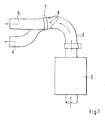
- the exhaust system 1 for a motor vehicle which is only partially illustrated, comprises an end muffler 2, which is adjoined upstream by an exhaust gas outlet pipe 3 and one or more exhaust gas tailpipes 4 and 5.
- the muffler 2 and the exhaust pipes 3, 4 and 5 are flowed through in the direction of arrow exhaust gases from an internal combustion engine.
- openings 6 are arranged in the exhaust gas outlet pipe 3 in the exhaust gas outlet pipe 3 in the exhaust gas outlet pipe 3 openings 6 are arranged.
- openings 6 are arranged annularly in the exhaust gas outlet pipe 3 and open directly outward into the ambient air.
- the openings 6 may have different opening shapes, such as circular, slot-shaped or polygonal. It can also be provided a mixed form of all opening shapes. It may also be perforations in the exhaust outlet pipe 3.
- the openings 6 may preferably be arranged close to a connection 7 of the exhaust gas outlet pipe 3 with the exhaust gas end pipe 4 and 5. At least four openings 6 or more are provided in the exhaust gas outlet pipe 3.
- the openings 6 may be covered by an insulating and / or absorbing material to obtain an additional tuning parameter and to seal against an exhaust gas outlet.
- the openings 6 are located in the exhaust gas outlet pipe 3 in such a way that a reduction of a single frequency of the exhaust gas stream as well as a resulting reduced overall noise level on the vehicle is achieved by the position and the geometric design of the openings 6 and their opening cross sections in a defined manner.
- FIGS. 2 and 3 are diagrams showing the individual noise levels, wherein in Fig. 2, the noise level without openings 6 in the exhaust gas outlet pipe 3 and in Fig. 3, the noise level with four openings 6 in the exhaust gas outlet pipe 3 are shown.
- a first vertical coordinate are the speeds and speeds of the vehicle and in the opposite second vertical coordinate are the strengths of the noise levels shown.
- the horizontal coordinate shows the distance to the front of the vehicle as the vehicle drives past the microphones.
- the noise level drops from 78dBF (A) at fourteen meters passing to 77dB (A), which significantly reduces the noise level brings with it.
- the level curves indicate a noise on the left and right side of the vehicle.
- the speed is represented by the characteristic curves 12, 12a and the speed by the characteristic curves 14, 14a.
Landscapes
- Engineering & Computer Science (AREA)
- Chemical & Material Sciences (AREA)
- Combustion & Propulsion (AREA)
- Mechanical Engineering (AREA)
- General Engineering & Computer Science (AREA)
- Exhaust Silencers (AREA)
Abstract
Description
- Die Erfindung bezieht sich auf eine Abgasanlage nach dem Oberbegriff des Anspruchs 1.
- Aus der
EP 0 582 106 A1 ist eine Abgasanlage für ein Kraftfahrzeug mit einem Auspuffrohr bekannt, das zweischalig mit ineinandergesteckten Rohren und einem zwischenliegenden Raum ausgeführt ist. Zur Reduzierung einer Oberflächentemperatur in dem äußeren Rohr sind in diesem mehrere kreisförmig angeordnete Öffnungen in dem Auspuffrohr vorgesehen. - Aufgabe der Erfindung ist es, eine Abgasanlage für ein Kraftfahrzeug zu schaffen, mit dem ein definiertes Geräuschverhalten hinsichtlich austretender Abgase erzielbar ist.
- Diese Aufgabe wird erfindungsgemäß durch die Merkmale des Anspruchs 1 gelöst. Weitere vorteilhafte Merkmale beinhalten die Unteransprüche.
- Die mit der Erfindung hauptsächlich erzielten Vorteile bestehen darin, dass eine Reduzierung der Einzelfrequenz am Abgas-Endrohr und in Abhängigkeit hiervon eine erhebliche Reduzierung eines Geräuschpegels des Fahrzeugs erzielbar ist. Dies wird nach der Erfindung dadurch erreicht, indem im Abgas-Ausgangsrohr Öffnungen kreisringförmig angeordnet sind, die unmittelbar nach außen in die Umgebungsluft ausmünden. Vorteilhafterweise sind die Öffnungen kreisförmig als Schlitz oder polygonal ausgeführt, wobei die Öffnungen unmittelbar vor einer Verbindung des Abgas-Endrohres mit dem Abgas-Ausgangsrohr angeordnet sind.
- Eine Abstimmung der Einzelfrequenz und somit des Gesamtgeräuschpegels kann definiert erfolgen, indem nach der Erfindung die Lage und Anzahl der Öffnungen im Abgas-Ausgangsrohr, deren Öffnungsquerschnitt sowie die geometrische Ausbildung der Öffnungen entsprechend ausgeführt wird.
- Die Öffnungen oder auch Perforationen im Abgas-Ausgangsrohr können nach der Erfindung z.B. durch Edelstahlwolle oder sonst wie durch isolierendes/absorbierendes Material abgedeckt sein. Dadurch wird sowohl ein zusätzlicher Abstimmungsparameter als auch eine Abdichtung des Abgas-Ausgangsrohres gegenüber einem Gasaustritt erzielt. Die Edelstahlwolle oder das isolierende/absorbierende Material kann das Abgas-Ausgangsrohr ummanteln.
- Die Öffnungen können in allen möglichen Formen und Anzahl eingebracht werden. Auch Kombinationen verschiedener Formen sind möglich. Hierdurch ist eine Abstimmung der Wirkung und des Geräuscheindrucks außerhalb (Außengeräusch) und innerhalb (Innengeräusch/Sound) erreichbar.
- Ein Ausführungsbeispiel der Erfindung ist in den Zeichnungen dargestellt und wird im Folgenden näher beschrieben.
- Es zeigen
- Fig. 1
- eine schematische Darstellung der Abgasanlage teilweise mit Endschalldämpfer und stromauf angeschlossenem Abgas-Ausgangsrohr und Abgas-Endrohr,
- Fig. 2
- ein Geräuschpegel-Diagramm ohne Öffnungen im Abgas-Ausgangsrohr und
- Fig. 3
- ein Geräuschpegel-Diagramm mit Öffnungen im Abgas-Ausgangsrohr.
- Die nur teilweise dargestellte Abgasanlage 1 für ein Kraftfahrzeug umfasst einen Endschalldämpfer 2, dem sich stromauf ein Abgas-Ausgangsrohr 3 und ein oder mehrere Abgas-Endrohre 4 und 5 anschließen. Der Endschalldämpfer 2 und die Abgasrohre 3, 4 und 5 werden in Pfeilrichtung von Abgasen aus einer Brennkraftmaschine durchströmt. Im Abgas-Ausgangsrohr 3 sind Öffnungen 6 angeordnet.
- Diese Öffnungen 6 sind kreisringförmig im Abgas-Ausgangsrohr 3 angeordnet und münden unmittelbar nach außen hin in die Umgebungsluft ein. Die Öffnungen 6 können verschiedene Öffnungsformen aufweisen, wie beispielsweise kreisförmig, schlitzförmig oder polygonal. Es kann auch eine Mischform aus allen Öffnungsformen vorgesehen sein. Es kann sich auch um Perforationen im Abgas-Ausgangsrohr 3 handeln.
- Wie Fig. 1 näher zeigt, können die Öffnungen 6 vorzugsweise nahe, einer Verbindung 7 des Abgas-Ausgangsrohres 3 mit dem Abgas-Endrohr 4 und 5 angeordnet sein. Es sind zumindest vier Öffnungen 6 oder auch mehr in dem Abgas-Ausgangsrohr 3 vorgesehen. Die Öffnungen 6 können durch ein isolierendes und/oder absorbierendes Material zur Erzielung eines zusätzlichen Abstimmungsparameters sowie zur Abdichtung gegen ein Abgasaustritt abgedeckt sein.
- Die Öffnungen 6 sind derart im Abgas-Ausgangsrohr 3 gelegen, dass durch die Lage und der geometrischen Ausbildung der Öffnungen 6 sowie deren Öffnungsquerschnitte in definierter Weise eine Reduzierung einer Einzelfrequenz des Abgasstromes sowie ein hierzu resultierender reduzierter Gesamtgeräuschpegel am Fahrzeug erreicht wird.
- In den Fig. 2 und 3 sind Diagramme mit den einzelnen Geräuschpegeln dargestellt, wobei in Fig. 2 die Geräuschpegel ohne Öffnungen 6 im Abgas-Ausgangsrohr 3 und in Fig. 3 die Geräuschpegel mit vier Öffnungen 6 im Abgas-Ausgangsrohr 3 dargestellt sind. In einer ersten senkrechten Koordinate sind die Drehzahlen und die Geschwindigkeiten des Fahrzeugs und in der gegenüberstehenden zweiten senkrechten Koordinate sind die Stärken der Geräuschpegel dargestellt. In der waagrechten Koordinate ist der Abstand zur Fahrzeugfront beim Vorbeifahren des Fahrzeugs an den Mikrofonen aufgezeigt.
- Wie aus der Maximalposition I und der Minimalposition II der Pegelkennlinie 10, 11 und 10a, 11a in den Diagrammen zu erkennen ist, sinkt der Geräuschpegel von 78dBF(A) bei vierzehn Meter Vorbeifahrt auf 77dB(A) ab, was eine wesentliche Verminderung des Geräuschpegels mit sich bringt. Die Pegelkennlinien kennzeichnen ein Geräusch an der linken und rechten Fahrzeugseite. Die Geschwindigkeit wird durch die Kennlinien 12, 12a und die Drehzahl durch die Kennlinien 14, 14a dargestellt.
Claims (6)
- Abgasanlage für ein Kraftfahrzeug mit einem stromab zu einem Endschalldämpfer angeordnetem Abgas-Ausgangsrohr, welches in wenigstens ein Abgas-Endrohr einmündet und die Abgase vom Abgas-Endrohr in die Umgebungsluft abführbar ist, dadurch gekennzeichnet, dass im Abgas-Ausgangsrohr (3) Öffnungen (6) kreisringförmig angeordnet sind, die unmittelbar nach außen in die Umgebungsluft ausmünden.
- Abgasanlage nach Anspruch 1, dadurch gekennzeichnet, dass die Öffnungen (6) kreisförmig als Schlitz oder polygonal ausgeführt sind.
- Abgasanlage nach den Ansprüchen 1 oder 2, dadurch gekennzeichnet, dass die Öffnungen (6) unmittelbar vor einer Verbindung (7) des Abgas-Endrohres (4, 5) mit dem Abgas-Ausgangsrohr (3) angeordnet sind.
- Abgasanlage nach einem der vorhergehenden Ansprüche, dadurch gekennzeichnet, dass zumindest vier Öffnungen (6) im Abgas-Ausgangsohr (3) angeordnet sind, die einen gleichen Abstand zueinander aufweisen.
- Abgasanlage nach einem der vorhergehenden Ansprüche, dadurch gekennzeichnet, dass die Öffnungen (6) derart im Abgas-Ausgangsrohr (3) lagemäßig angeordnet und geometrisch ausgebildet sind, dass eine Reduzierung der Einzelfrequenz und ein hieraus resultierender reduzierter Geräuschpegel erzielbar ist.
- Abgasanlage nach einem der vorhergehenden Ansprüche, dadurch gekennzeichnet, dass die Öffnungen (6) durch ein isolierendes und/oder absorbierendes Material zur Erzielung eines zusätzlichen Abstimmungsparameters und zur Abdichtung gegen Abgasaustritt erzielbar ist.
Applications Claiming Priority (1)
| Application Number | Priority Date | Filing Date | Title |
|---|---|---|---|
| DE200610009323 DE102006009323A1 (de) | 2006-03-01 | 2006-03-01 | Abgasanlage |
Publications (2)
| Publication Number | Publication Date |
|---|---|
| EP1830044A1 true EP1830044A1 (de) | 2007-09-05 |
| EP1830044B1 EP1830044B1 (de) | 2008-08-27 |
Family
ID=37806898
Family Applications (1)
| Application Number | Title | Priority Date | Filing Date |
|---|---|---|---|
| EP20070001694 Ceased EP1830044B1 (de) | 2006-03-01 | 2007-01-26 | Abgasanlage |
Country Status (2)
| Country | Link |
|---|---|
| EP (1) | EP1830044B1 (de) |
| DE (2) | DE102006009323A1 (de) |
Families Citing this family (2)
| Publication number | Priority date | Publication date | Assignee | Title |
|---|---|---|---|---|
| DE102008064017A1 (de) | 2008-12-19 | 2010-06-24 | Daimler Ag | Abgasanlage für eine Brennkraftmaschine |
| CN112548026B (zh) * | 2020-11-04 | 2022-07-29 | 青岛立博汽车零部件精密铸造有限公司 | 排气端锥及模具 |
Citations (4)
| Publication number | Priority date | Publication date | Assignee | Title |
|---|---|---|---|---|
| US1521074A (en) * | 1922-01-07 | 1924-12-30 | Carr Sidney Lee | Muffler for internal-combustion engines |
| US2112534A (en) * | 1935-04-20 | 1938-03-29 | John S Keen | Locomotive engine exhaust |
| US6220387B1 (en) * | 1999-10-21 | 2001-04-24 | Mathew S. Hoppes | Exhaust muffler |
| EP1607594A1 (de) * | 2004-06-17 | 2005-12-21 | GGP Sweden AB | Abgasschalldämpfer für Brennkraftmaschine |
-
2006
- 2006-03-01 DE DE200610009323 patent/DE102006009323A1/de not_active Withdrawn
-
2007
- 2007-01-26 EP EP20070001694 patent/EP1830044B1/de not_active Ceased
- 2007-01-26 DE DE200750000083 patent/DE502007000083D1/de active Active
Patent Citations (4)
| Publication number | Priority date | Publication date | Assignee | Title |
|---|---|---|---|---|
| US1521074A (en) * | 1922-01-07 | 1924-12-30 | Carr Sidney Lee | Muffler for internal-combustion engines |
| US2112534A (en) * | 1935-04-20 | 1938-03-29 | John S Keen | Locomotive engine exhaust |
| US6220387B1 (en) * | 1999-10-21 | 2001-04-24 | Mathew S. Hoppes | Exhaust muffler |
| EP1607594A1 (de) * | 2004-06-17 | 2005-12-21 | GGP Sweden AB | Abgasschalldämpfer für Brennkraftmaschine |
Also Published As
| Publication number | Publication date |
|---|---|
| EP1830044B1 (de) | 2008-08-27 |
| DE502007000083D1 (de) | 2008-10-09 |
| DE102006009323A1 (de) | 2007-09-06 |
Similar Documents
| Publication | Publication Date | Title |
|---|---|---|
| EP1914398B1 (de) | Abgasnachschalldämpfer | |
| EP2161423B1 (de) | Abgasanlage für Dieselfahrzeuge mit einem SCR-Katalysator | |
| EP2610457B1 (de) | Abgasbehandlungsvorrichtung | |
| EP0506686B1 (de) | Abgasleitung mit wendelförmig angeströmtem katalysator-trägerkörper | |
| EP1510667B1 (de) | Schalldämpfer | |
| EP2126294A1 (de) | Abgasnachbehandlungseinrichtung eines kraftfahrzeugs | |
| EP0401195B1 (de) | Auspuffanlage, insbesondere für Zweitakt-Brennkraftmaschinen | |
| EP1475522A2 (de) | Kombinierte Abgasnachbehandlungs-/Schalldämpfungsvorrichtung im Abgasstrang einer Brennkraftmaschine | |
| EP1830044B1 (de) | Abgasanlage | |
| EP0120181B1 (de) | Absorptionsschalldämpfer für gasdynamische Druckwellenmaschinen | |
| EP3018315B1 (de) | Katalysatoreinrichtung für eine stationäre brennkraftmaschine | |
| DE7307335U (de) | Abgasschalldaempfer fuer zweitakt- motore | |
| EP0674747B1 (de) | Schalldämpfer | |
| EP1798390B2 (de) | Abgasanlage für Brennkraftmaschinen | |
| EP3420208B1 (de) | Vorrichtung zum behandeln eines abgasstromes | |
| EP1437489A1 (de) | Abgasanlage | |
| DE29512732U1 (de) | Schalldämpfer für die Abgasanlage eines Verbrennungsmotors | |
| DE4244613A1 (de) | Katalysatorvorrichtung für Abgasanlagen von Kraftfahrzeugen | |
| DE20116088U1 (de) | Abgasanlage | |
| DE3149632A1 (de) | Abgas-schalldaempfer fuer brennkraftmaschinen | |
| DE2741716C2 (de) | Absorptions-Nachschalldämpfer für Brennkraftmaschinen | |
| EP1873364A1 (de) | Schalldämpfer | |
| WO1998019054A1 (de) | Schalldämpfer | |
| DE102020108440A1 (de) | Abgasstrang für ein Fahrzeug sowie Fahrzeug mit einem Abgasstrang | |
| DE19838314A1 (de) | Vorrichtung zur Reduzierung des Lärms in gasführenden Rohrleitungen |
Legal Events
| Date | Code | Title | Description |
|---|---|---|---|
| PUAI | Public reference made under article 153(3) epc to a published international application that has entered the european phase |
Free format text: ORIGINAL CODE: 0009012 |
|
| AK | Designated contracting states |
Kind code of ref document: A1 Designated state(s): AT BE BG CH CY CZ DE DK EE ES FI FR GB GR HU IE IS IT LI LT LU LV MC NL PL PT RO SE SI SK TR |
|
| AX | Request for extension of the european patent |
Extension state: AL BA HR MK YU |
|
| 17P | Request for examination filed |
Effective date: 20080305 |
|
| GRAP | Despatch of communication of intention to grant a patent |
Free format text: ORIGINAL CODE: EPIDOSNIGR1 |
|
| AKX | Designation fees paid |
Designated state(s): DE ES FR GB IT |
|
| RAP1 | Party data changed (applicant data changed or rights of an application transferred) |
Owner name: DR. ING. H.C. F. PORSCHE AKTIENGESELLSCHAFT |
|
| RAP1 | Party data changed (applicant data changed or rights of an application transferred) |
Owner name: DR. ING. H.C. F. PORSCHE AKTIENGESELLSCHAFT |
|
| GRAS | Grant fee paid |
Free format text: ORIGINAL CODE: EPIDOSNIGR3 |
|
| GRAA | (expected) grant |
Free format text: ORIGINAL CODE: 0009210 |
|
| AK | Designated contracting states |
Kind code of ref document: B1 Designated state(s): DE ES FR GB IT |
|
| REG | Reference to a national code |
Ref country code: GB Ref legal event code: FG4D Free format text: NOT ENGLISH |
|
| REF | Corresponds to: |
Ref document number: 502007000083 Country of ref document: DE Date of ref document: 20081009 Kind code of ref document: P |
|
| PG25 | Lapsed in a contracting state [announced via postgrant information from national office to epo] |
Ref country code: ES Free format text: LAPSE BECAUSE OF FAILURE TO SUBMIT A TRANSLATION OF THE DESCRIPTION OR TO PAY THE FEE WITHIN THE PRESCRIBED TIME-LIMIT Effective date: 20081208 |
|
| PLBE | No opposition filed within time limit |
Free format text: ORIGINAL CODE: 0009261 |
|
| STAA | Information on the status of an ep patent application or granted ep patent |
Free format text: STATUS: NO OPPOSITION FILED WITHIN TIME LIMIT |
|
| 26N | No opposition filed |
Effective date: 20090528 |
|
| REG | Reference to a national code |
Ref country code: FR Ref legal event code: TP |
|
| REG | Reference to a national code |
Ref country code: GB Ref legal event code: 732E Free format text: REGISTERED BETWEEN 20110310 AND 20110316 |
|
| REG | Reference to a national code |
Ref country code: GB Ref legal event code: 732E Free format text: REGISTERED BETWEEN 20110331 AND 20110406 |
|
| PGFP | Annual fee paid to national office [announced via postgrant information from national office to epo] |
Ref country code: IT Payment date: 20110121 Year of fee payment: 5 |
|
| PGRI | Patent reinstated in contracting state [announced from national office to epo] |
Ref country code: IT Effective date: 20110501 |
|
| PG25 | Lapsed in a contracting state [announced via postgrant information from national office to epo] |
Ref country code: IT Free format text: LAPSE BECAUSE OF NON-PAYMENT OF DUE FEES Effective date: 20120126 |
|
| REG | Reference to a national code |
Ref country code: FR Ref legal event code: PLFP Year of fee payment: 10 |
|
| REG | Reference to a national code |
Ref country code: FR Ref legal event code: PLFP Year of fee payment: 11 |
|
| REG | Reference to a national code |
Ref country code: FR Ref legal event code: PLFP Year of fee payment: 12 |
|
| PGFP | Annual fee paid to national office [announced via postgrant information from national office to epo] |
Ref country code: GB Payment date: 20180119 Year of fee payment: 12 |
|
| PGFP | Annual fee paid to national office [announced via postgrant information from national office to epo] |
Ref country code: FR Payment date: 20180119 Year of fee payment: 12 |
|
| GBPC | Gb: european patent ceased through non-payment of renewal fee |
Effective date: 20190126 |
|
| PG25 | Lapsed in a contracting state [announced via postgrant information from national office to epo] |
Ref country code: FR Free format text: LAPSE BECAUSE OF NON-PAYMENT OF DUE FEES Effective date: 20190131 |
|
| PG25 | Lapsed in a contracting state [announced via postgrant information from national office to epo] |
Ref country code: GB Free format text: LAPSE BECAUSE OF NON-PAYMENT OF DUE FEES Effective date: 20190126 |
|
| PGFP | Annual fee paid to national office [announced via postgrant information from national office to epo] |
Ref country code: DE Payment date: 20200115 Year of fee payment: 14 |
|
| REG | Reference to a national code |
Ref country code: DE Ref legal event code: R119 Ref document number: 502007000083 Country of ref document: DE |
|
| PG25 | Lapsed in a contracting state [announced via postgrant information from national office to epo] |
Ref country code: DE Free format text: LAPSE BECAUSE OF NON-PAYMENT OF DUE FEES Effective date: 20210803 |