EP1829810A1 - Crane control device - Google Patents
Crane control device Download PDFInfo
- Publication number
- EP1829810A1 EP1829810A1 EP05820341A EP05820341A EP1829810A1 EP 1829810 A1 EP1829810 A1 EP 1829810A1 EP 05820341 A EP05820341 A EP 05820341A EP 05820341 A EP05820341 A EP 05820341A EP 1829810 A1 EP1829810 A1 EP 1829810A1
- Authority
- EP
- European Patent Office
- Prior art keywords
- container
- yard
- spreader
- slope
- containers
- Prior art date
- Legal status (The legal status is an assumption and is not a legal conclusion. Google has not performed a legal analysis and makes no representation as to the accuracy of the status listed.)
- Withdrawn
Links
Images




Classifications
-
- B—PERFORMING OPERATIONS; TRANSPORTING
- B66—HOISTING; LIFTING; HAULING
- B66C—CRANES; LOAD-ENGAGING ELEMENTS OR DEVICES FOR CRANES, CAPSTANS, WINCHES, OR TACKLES
- B66C13/00—Other constructional features or details
- B66C13/18—Control systems or devices
- B66C13/46—Position indicators for suspended loads or for crane elements
-
- B—PERFORMING OPERATIONS; TRANSPORTING
- B65—CONVEYING; PACKING; STORING; HANDLING THIN OR FILAMENTARY MATERIAL
- B65G—TRANSPORT OR STORAGE DEVICES, e.g. CONVEYORS FOR LOADING OR TIPPING, SHOP CONVEYOR SYSTEMS OR PNEUMATIC TUBE CONVEYORS
- B65G63/00—Transferring or trans-shipping at storage areas, railway yards or harbours or in opening mining cuts; Marshalling yard installations
-
- B—PERFORMING OPERATIONS; TRANSPORTING
- B66—HOISTING; LIFTING; HAULING
- B66C—CRANES; LOAD-ENGAGING ELEMENTS OR DEVICES FOR CRANES, CAPSTANS, WINCHES, OR TACKLES
- B66C13/00—Other constructional features or details
- B66C13/04—Auxiliary devices for controlling movements of suspended loads, or preventing cable slack
- B66C13/08—Auxiliary devices for controlling movements of suspended loads, or preventing cable slack for depositing loads in desired attitudes or positions
-
- B—PERFORMING OPERATIONS; TRANSPORTING
- B66—HOISTING; LIFTING; HAULING
- B66C—CRANES; LOAD-ENGAGING ELEMENTS OR DEVICES FOR CRANES, CAPSTANS, WINCHES, OR TACKLES
- B66C13/00—Other constructional features or details
- B66C13/18—Control systems or devices
- B66C13/48—Automatic control of crane drives for producing a single or repeated working cycle; Program control
-
- B—PERFORMING OPERATIONS; TRANSPORTING
- B66—HOISTING; LIFTING; HAULING
- B66C—CRANES; LOAD-ENGAGING ELEMENTS OR DEVICES FOR CRANES, CAPSTANS, WINCHES, OR TACKLES
- B66C19/00—Cranes comprising trolleys or crabs running on fixed or movable bridges or gantries
- B66C19/007—Cranes comprising trolleys or crabs running on fixed or movable bridges or gantries for containers
Definitions
- the present invention relates to a yard crane control device, which, in a container yard where a number of boxshaped containers are stored, within a port or a harbor for example, transports the containers.
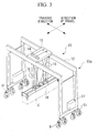
- FIG. 3 denotes a yard crane (referred to hereunder as a crane) that stacks a container C, being a suspended load, on a target container.
- the crane 10 is a tire type gantry crane that stacks containers, and has a traveling crane body 10a that travels on a trackless surface via wheeled traveling devices 11, which are fitted with tires 9.
- the wheeled traveling devices 11 are provided at the front and back of the crane 10, and movement traveling inside lanes, and movement traversing between lanes, are possible.
- a traverse trolley 13 is provided on a horizontal upper beam 12 of the traveling crane body 10a, which moves horizontally along the upper beam 12.
- Hoist gear 14 is mounted on the traverse trolley 13.
- a container suspension device (spreader) 16 is suspended by a suspension cable 15, which is hoisted and fed by the hoist gear 14.
- the suspension device 16 can hold the container C, being a suspended load, such that it can be engaged or disengaged.
- the traveling crane body 10a is provided with a travel control unit 17 which performs travel control of the yard crane 10.
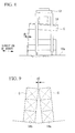
- FIG. 4 shows a locking pin device 20 provided on the spreader 16 to hold the container C.
- the locking pin device 20 which is provided at the corners of the spreader 16, comprises; a locking pin 21 which is suspended such that its movement in the vertical direction is constrained and such that it can be rotated freely, a locking section 22 which is provided at the corners of the container C facing the locking pin 21, and into which the end 21a of the locking pin 21 is inserted, and a rotation mechanism 25 which rotates the locking pin 21.
- a narrow pin slot 22a is provided in the locking section 22.
- a landing detection device 23 is positioned close to the locking pin 21, and comprises; a detection rod 28 which moves vertically inside a through hole 16b that opens to the bottom 16a of the spreader 16, and a limit switch (landing detection device) 27 which detects the movement of the detection rod 28.
- the tip 28b of the detection rod 28 protrudes from the bottom of the spreader at normal times (when in an unloaded state) due to a spring 28c.
- the detection rod 28 is pushed up. After the movement is detected by the limit switch 27, and landing is confirmed, the locking pin 21 is locked.
- FIG. 6 shows a container yard in which such a crane is used.
- a plurality of lanes 18 is provided in the container yard, and one or more cranes 10 is provided in each lane 18.
- the cranes 10 load desired containers C in the container yard onto vehicles 19, or unload the containers C in the container yard from the vehicles 19.
- ramps are provided for drainage in the storage areas (central areas in the widthwise direction of lanes 18) where the containers C are stacked and the crane travel areas (areas provided on the two sides in the widthwise direction of the storage areas in the lanes 18).
- the ramps vary due to unevenness at each location, or due to uneven settling occurring after the construction of the container yard. For example, if the storage area 18a slopes in the traverse direction (horizontal direction in FIG. 7) as shown in FIG. 7, the container C that the spreader 16 holds cannot be parallel to a container C' stacked in the storage area 18a.
- the slope of the storage areas 18a and 18a are different, a gap d2 between adjacent containers is less than or equal to a predetermined amount (400mm) that must be ensured for the movement of the spreader 16, and it is difficult to insert the spreader 16 in the gap d2, which makes handling difficult. Due to such reasons, a lot of expertise is required in order to land the containers C manually, and in order to land the containers C automatically, there is a problem in that it is difficult to deal with the case where the angle of slope is large.
- the present invention has been made in consideration of the above circumstances, with an object of providing a yard crane control device that can detect the slope of the yard automatically, and can stack containers accurately.
- the present invention uses the following means in order to solve the above problems.
- the present invention provides a yard crane control device for a yard crane that suspends containers using a spreader and transports them in a container yard, comprising: an inclinometer which is provided on the spreader to detect the slope of the spreader; a landing detection device which detects a landing state of the spreader in relation to the container; and a slope data storage device which stores the detection results of the inclinometer when the landing detection device detects that the spreader has landed on the container, in relation to a storage area location in the container yard where the containers are stored.
- the slope data stored in the slope data storage device are used in manual or automatic control of the yard crane when containers are transported. By so doing, it is possible to transport containers reliably. Furthermore, the slope data stored in the slope data storage device can be updated progressively.
- a central control unit that controls the trim and the list of the spreader such that it is parallel to the storage area where the container is stacked, based on the slope data stored in the slope data storage device.
- the central control unit controls the trim and the list of the spreader such that the container to be stacked is parallel to the storage area where it is to be stacked. Accordingly, the whole container to be stacked can touch the ground at almost the same time, thus making it possible to prevent the container from rolling.
- a central control unit that calculates the location along the direction of travel of a top container in the storage area where the container is stacked, based on the slope data stored in the slope data storage device, and corrects the direction of travel and the location of the yard crane.
- the central control unit calculates the deviation based on the slope data, and correcting the travel distance, it is possible to improve the accuracy of the container storage location.
- the number of containers in the stacks of containers in the storage area may be controlled by the central control unit.
- a central control unit that calculates the distance of the spacing between the container onto which a container is stacked and the adjacent container, based on the slope data stored in the slope data storage device.
- the central control unit calculates the decrease in spacing between adjacent containers, it is possible to have the central control unit perform processes such as limiting the number in the stack, triggering an alarm, and the like, which helps to avoid the danger of containers colliding.
- a central control unit that controls a plurality of the abovementioned yard cranes is provided, and that the detection result of the inclinometer is transmitted to the central control unit from the plurality of yard cranes, and that the plurality of yard cranes is controlled by the central control unit.
- the slope of each storage area location in the whole container yard is managed by the central control unit, and all of the yard cranes are controlled collectively by the central control unit.
- the following effects can be obtained.
- detecting the slopes of the container yard automatically, and storing and updating them in a database it is possible to eliminate the need to measure the slopes manually.
- Furthermore, based on the database it is possible to control the spreader reliably when stacking the containers, and it is possible to correct the location of the spreader automatically, thus making it possible to improve the handling efficiency.
- FIG. 1 is a block diagram of a yard crane control device according to the present embodiment.
- the schematic structure of a yard crane 40 of the present embodiment is the same as the above described conventional crane 10, and the same reference symbols are used for the same structures, and hence the descriptions are omitted.
- the component denoted by reference symbol 41 is an inclinometer fixed to the spreader 16.
- the inclinometer 41 detects the slope (angle of slope and direction of slope) of the spreader 16, and a liquid surface type one or gravity-type one can be used.
- FIG. 1 is a block diagram of a yard crane control device according to the present embodiment.
- the schematic structure of a yard crane 40 of the present embodiment is the same as the above described conventional crane 10, and the same reference symbols are used for the same structures, and hence the descriptions are omitted.
- the component denoted by reference symbol 41 is an inclinometer fixed to the spreader 16.
- the inclinometer 41 detects the slope (angle of slope and direction of slope) of the spreader 16, and a liquid surface type one or
- the component denoted by reference symbol 42 is a traverse encoder for detecting the amount of traverse of a tire 9
- the component denoted by reference symbol 43 is a GPS (global positioning system) device for detecting the position of a crane in a container yard using radio waves from GPS satellites.
- the component denoted by reference symbol 50 is a central computer (central control unit) on the container yard side.
- the components denoted by reference symbols 45 and 46 are radio devices for receiving and sending data between the crane and the central computer 50 on the container yard side.
- the central computer 50 is constructed such that it accesses a database (slope data storage device) 51 where slope data of the container yard are stored.
- the central computer 50 controls the travel of a plurality of the cranes 40 provided in the container yard, by controlling a plurality of travel control units 17 via the radio devices 45 and 46. Moreover, the central computer 50 controls the number of containers stacked in each storage area location.
- the output of the inclinometer 41 when the limit switch 27 is turned on that is, when the spreader 16 lands on the container C
- the traverse location of the yard crane 40 detected by the traverse encoder 42, and the travel position of the yard crane 40 detected by the GPS device 43 are input to the central computer 50 via the radio devices 45 and 46.
- the slope of the spreader 16 is equal to the slope of the storage area 18a in which the container C is stacked.
- the slope detected by the inclinometer 41 can be regarded as the slope of the storage area 18a.
- the central computer 50 stores the slope in the database 51 in relation to the coordinates of the storage location. By doing this repeatedly, a database indicating the angle of the slope at each storage area location in the container yard is accumulated and updated.
- the database 51 is used as follows.
- the database 51 is used for a function for automatically adjusting the trim (angle of the spreader in the direction of travel) and list (angle of the spreader in the traverse direction) in relation to the slope of the storage area 18a and the slope of the crane traveling area 18b. That is, the central computer 50 reads the slope data of the location where the stacking takes place from the database 51, and adjusts the suspension amount of the right and left of the spreader 16 via the radio devices 45 and 46 such that the suspended container C is parallel with the containers that are stacked in the storage area 18a while landing the container C that is held. Accordingly, it is possible to prevent the container C from rolling when the container is landed.
- the central computer 50 can improve the container storage location accuracy by calculating the shift based on the slope data, and correcting the travel distance.
- the central computer 50 may trigger an alarm. This helps to avoid the danger of containers colliding.
- this yard crane control device uses this yard crane control device to detect large variations in the slope of the storage area 18a. Furthermore, it is possible to devise preventative operational measures such as avoiding, whenever possible, placing containers in locations where the slope varies significantly. Moreover, in the case where the angle of the slope of the storage area 18a exceeds an appropriate value, it is possible to determine that the container yard needs to be repaired. Accordingly, the container yard can be maintained in an appropriate condition.
- the slope of the container yard can be detected automatically and stored in a database, and variations in the slope can be updated automatically. Accordingly, it is possible to eliminate the need to measure the slope manually. Furthermore, it is possible to control the spreader 16 to stack containers reliably based on the database, and it is possible to correct shifting of the container location in the direction of travel automatically, which enables the handling efficiency to be improved.
Landscapes
- Engineering & Computer Science (AREA)
- Mechanical Engineering (AREA)
- Automation & Control Theory (AREA)
- Control And Safety Of Cranes (AREA)
Abstract
Description
- The present invention relates to a yard crane control device, which, in a container yard where a number of boxshaped containers are stored, within a port or a harbor for example, transports the containers.
- In a container yard at a port, a harbor, or the like, cranes perform handling such as loading containers onto ships or trailers, and unloading containers from ships or trailers.
An example of a crane used for this handling will be described using FIG. 3.
Reference symbol 10 in FIG. 3 denotes a yard crane (referred to hereunder as a crane) that stacks a container C, being a suspended load, on a target container.
Thecrane 10 is a tire type gantry crane that stacks containers, and has a travelingcrane body 10a that travels on a trackless surface via wheeled traveling devices 11, which are fitted with tires 9. The wheeled traveling devices 11 are provided at the front and back of thecrane 10, and movement traveling inside lanes, and movement traversing between lanes, are possible. - A
traverse trolley 13 is provided on a horizontalupper beam 12 of the travelingcrane body 10a, which moves horizontally along theupper beam 12. Hoistgear 14 is mounted on thetraverse trolley 13. A container suspension device (spreader) 16 is suspended by asuspension cable 15, which is hoisted and fed by thehoist gear 14. Thesuspension device 16 can hold the container C, being a suspended load, such that it can be engaged or disengaged.
Furthermore, the travelingcrane body 10a is provided with atravel control unit 17 which performs travel control of theyard crane 10. - FIG. 4 shows a
locking pin device 20 provided on thespreader 16 to hold the container C. Thelocking pin device 20 which is provided at the corners of thespreader 16, comprises; alocking pin 21 which is suspended such that its movement in the vertical direction is constrained and such that it can be rotated freely, alocking section 22 which is provided at the corners of the container C facing thelocking pin 21, and into which theend 21a of thelocking pin 21 is inserted, and arotation mechanism 25 which rotates thelocking pin 21. - A
narrow pin slot 22a is provided in thelocking section 22. After thespreader 16 is lowered and thelocking pin tip 21a is inserted into thepin slot 22a, by driving a hydraulic cylinder (not shown in the figure) to operate arotation mechanism 25, and rotating thelocking pin 21 via anarm 24 connected with therotation mechanism 25, the container C is locked to or unlocked from thespreader 16 via thelocking pin 21. Furthermore, a landing detection device is provided at the corners of thespreader 16 in order to verify the locking state of thelocking pin 21. - As shown in FIG. 5, a
landing detection device 23 is positioned close to thelocking pin 21, and comprises; a detection rod 28 which moves vertically inside athrough hole 16b that opens to thebottom 16a of thespreader 16, and a limit switch (landing detection device) 27 which detects the movement of the detection rod 28.
Thetip 28b of the detection rod 28 protrudes from the bottom of the spreader at normal times (when in an unloaded state) due to aspring 28c. When thespreader 16 is lowered, approaching the top face of the container C, and makes contact with it, the detection rod 28 is pushed up. After the movement is detected by thelimit switch 27, and landing is confirmed, thelocking pin 21 is locked. - FIG. 6 shows a container yard in which such a crane is used. A plurality of
lanes 18 is provided in the container yard, and one ormore cranes 10 is provided in eachlane 18. By moving in each of thelanes 18, thecranes 10 load desired containers C in the container yard ontovehicles 19, or unload the containers C in the container yard from thevehicles 19. - Patent Document 1:
Japanese Unexamined Patent Application, Publication No. Hei 5-40813 - Patent Document 2:
Japanese Unexamined Patent Application, Publication No. Hei 11-157485 - In the container yard, ramps are provided for drainage in the storage areas (central areas in the widthwise direction of lanes 18) where the containers C are stacked and the crane travel areas (areas provided on the two sides in the widthwise direction of the storage areas in the lanes 18). The ramps vary due to unevenness at each location, or due to uneven settling occurring after the construction of the container yard.
For example, if thestorage area 18a slopes in the traverse direction (horizontal direction in FIG. 7) as shown in FIG. 7, the container C that thespreader 16 holds cannot be parallel to a container C' stacked in thestorage area 18a. Therefore, there is a case in which, when the suspended container C is landed on the container C' in thestorage area 18a, part of the container C touches before the rest, so it rolls.
Moreover, in the case where thestorage area 18a slopes in the direction of travel as shown in FIG. 8, similar rolling of the container occurs, and in addition, if the angle of slope in the direction of travel (horizontal direction in FIG. 8) increases, the position of the container on the top shifts in the direction of travel as the height of the stack increases (refer to reference symbol d1 in the figure). That is, fine adjustment of the crane travel position is necessary as stacking proceeds, which has an adverse effect on the handling efficiency.
Furthermore, if as shown in FIG. 9, the slope of thestorage areas spreader 16, and it is difficult to insert thespreader 16 in the gap d2, which makes handling difficult.
Due to such reasons, a lot of expertise is required in order to land the containers C manually, and in order to land the containers C automatically, there is a problem in that it is difficult to deal with the case where the angle of slope is large. - The present invention has been made in consideration of the above circumstances, with an object of providing a yard crane control device that can detect the slope of the yard automatically, and can stack containers accurately.
The present invention uses the following means in order to solve the above problems.
The present invention provides a yard crane control device for a yard crane that suspends containers using a spreader and transports them in a container yard, comprising: an inclinometer which is provided on the spreader to detect the slope of the spreader; a landing detection device which detects a landing state of the spreader in relation to the container; and a slope data storage device which stores the detection results of the inclinometer when the landing detection device detects that the spreader has landed on the container, in relation to a storage area location in the container yard where the containers are stored. - In the present invention, it is possible to detect the slope of each storage location in a container yard, each of which may be different from the slope of the yard crane itself. The slope data (data of slope angle and slope direction) stored in the slope data storage device are used in manual or automatic control of the yard crane when containers are transported. By so doing, it is possible to transport containers reliably. Furthermore, the slope data stored in the slope data storage device can be updated progressively.
- In the above invention, it is preferable to provide a central control unit that controls the trim and the list of the spreader such that it is parallel to the storage area where the container is stacked, based on the slope data stored in the slope data storage device.
- In this case, according to the slope of the container yard storage area where the stacking takes place, the central control unit controls the trim and the list of the spreader such that the container to be stacked is parallel to the storage area where it is to be stacked. Accordingly, the whole container to be stacked can touch the ground at almost the same time, thus making it possible to prevent the container from rolling.
- In the above invention, it is preferable to provide a central control unit that calculates the location along the direction of travel of a top container in the storage area where the container is stacked, based on the slope data stored in the slope data storage device, and corrects the direction of travel and the location of the yard crane.
- When the container is stacked on a yard that slopes in the direction of travel, the position of the top container shifts in the direction of travel as the height of the stack increases. Therefore, as described above, by the central control unit calculating the deviation based on the slope data, and correcting the travel distance, it is possible to improve the accuracy of the container storage location. Here, the number of containers in the stacks of containers in the storage area may be controlled by the central control unit.
- In the above invention, it is preferable to provide a central control unit that calculates the distance of the spacing between the container onto which a container is stacked and the adjacent container, based on the slope data stored in the slope data storage device.
- If the slope of the storage area is not uniform, when the number of containers stacked is increased, the spacing between adjacent containers becomes less than or equal to a predetermined value. Therefore, as described above, by the central control unit calculating the decrease in spacing between adjacent containers, it is possible to have the central control unit perform processes such as limiting the number in the stack, triggering an alarm, and the like, which helps to avoid the danger of containers colliding.
- In the above invention, it is preferable that a central control unit that controls a plurality of the abovementioned yard cranes is provided, and that the detection result of the inclinometer is transmitted to the central control unit from the plurality of yard cranes, and that the plurality of yard cranes is controlled by the central control unit.
- In this case, the slope of each storage area location in the whole container yard is managed by the central control unit, and all of the yard cranes are controlled collectively by the central control unit.
- In the present invention, the following effects can be obtained.
By detecting the slopes of the container yard automatically, and storing and updating them in a database, it is possible to eliminate the need to measure the slopes manually. Furthermore, based on the database, it is possible to control the spreader reliably when stacking the containers, and it is possible to correct the location of the spreader automatically, thus making it possible to improve the handling efficiency. -
- [FIG. 1] is a block diagram of a yard crane control device according to the present embodiment.
- [FIG. 2] is a diagram showing the slope of a spreader when a container is landed.
- [FIG. 3] is a perspective view of a yard crane.
- [FIG. 4] is a longitudinal sectional view showing a locking pin device provided on the spreader.
- [FIG. 5] is a longitudinal sectional view showing a limit switch of the locking pin device as shown in FIG. 4.
- [FIG. 6] is a perspective view showing the whole container yard.
- [FIG. 7] is a diagram showing the slope of the storage area in the traverse direction.
- [FIG. 8] is a diagram showing the slope of the storage area in the direction of travel.
- [FIG. 9] is a diagram showing non-uniform slopes in the storage area.
- Next is a description of an embodiment of the present invention with reference to the drawings.
FIG. 1 is a block diagram of a yard crane control device according to the present embodiment. The schematic structure of ayard crane 40 of the present embodiment is the same as the above describedconventional crane 10, and the same reference symbols are used for the same structures, and hence the descriptions are omitted.
In FIG. 1, the component denoted byreference symbol 41 is an inclinometer fixed to thespreader 16. Theinclinometer 41 detects the slope (angle of slope and direction of slope) of thespreader 16, and a liquid surface type one or gravity-type one can be used.
In FIG. 1, the component denoted byreference symbol 42 is a traverse encoder for detecting the amount of traverse of a tire 9, and the component denoted byreference symbol 43 is a GPS (global positioning system) device for detecting the position of a crane in a container yard using radio waves from GPS satellites. Furthermore, the component denoted byreference symbol 50 is a central computer (central control unit) on the container yard side. The components denoted byreference symbols central computer 50 on the container yard side. Thecentral computer 50 is constructed such that it accesses a database (slope data storage device) 51 where slope data of the container yard are stored. Furthermore, thecentral computer 50 controls the travel of a plurality of thecranes 40 provided in the container yard, by controlling a plurality oftravel control units 17 via theradio devices central computer 50 controls the number of containers stacked in each storage area location. - In the yard crane control device constructed as above, when landing a
spreader 16 on a container C; the output of theinclinometer 41 when thelimit switch 27 is turned on (that is, when thespreader 16 lands on the container C), the traverse location of theyard crane 40 detected by thetraverse encoder 42, and the travel position of theyard crane 40 detected by theGPS device 43, are input to thecentral computer 50 via theradio devices spreader 16 that holds the container C stacked on astorage area 18a lands on the container C, the slope of thespreader 16 is equal to the slope of thestorage area 18a in which the container C is stacked. That is, at the time that thespreader 16 lands on the container C and thelimit switch 27 is turned on, the slope detected by theinclinometer 41 can be regarded as the slope of thestorage area 18a.
Thecentral computer 50 stores the slope in thedatabase 51 in relation to the coordinates of the storage location. By doing this repeatedly, a database indicating the angle of the slope at each storage area location in the container yard is accumulated and updated. - The
database 51 is used as follows.
Thedatabase 51 is used for a function for automatically adjusting the trim (angle of the spreader in the direction of travel) and list (angle of the spreader in the traverse direction) in relation to the slope of thestorage area 18a and the slope of thecrane traveling area 18b. That is, thecentral computer 50 reads the slope data of the location where the stacking takes place from thedatabase 51, and adjusts the suspension amount of the right and left of thespreader 16 via theradio devices storage area 18a while landing the container C that is held. Accordingly, it is possible to prevent the container C from rolling when the container is landed. - Furthermore, by adding a crane travel stopping location correction function in relation to the slopes of the
storage area 18a and thecrane traveling area 18b, and the height of the stack, to the yard crane control device, it is possible to correct mis-location of the container in the direction of travel due to the slopes of thestorage area 18a and thecrane traveling area 18b in the direction of travel.
As described above, when containers are stacked in astorage area 18a that slopes in the direction of travel, the location of the container on the top shifts in the direction of travel as the height of the stack increases (refer to FIG. 8). In the yard crane control device of the present embodiment, thecentral computer 50 can improve the container storage location accuracy by calculating the shift based on the slope data, and correcting the travel distance. - Moreover, if the slope in the storage area is not uniform, when the number of stacked containers increases, the gap between adjacent containers becomes less than or equal to a predetermined value (refer to FIG. 9). In the present embodiment, by the
central computer 50 calculating the decrease in the gap between adjacent containers, and limiting the number stacked by theyard crane 40 based on that information, it is possible to prevent the gap between containers from reaching the predetermined value or less. Accordingly, it is possible to avoid situations where containers are unable to be stored. Furthermore, in the case where the gap between containers is less than the predetermined value, thecentral computer 50 may trigger an alarm. This helps to avoid the danger of containers colliding. - Moreover, using this yard crane control device, large variations in the slope of the
storage area 18a can be detected. Furthermore, it is possible to devise preventative operational measures such as avoiding, whenever possible, placing containers in locations where the slope varies significantly. Moreover, in the case where the angle of the slope of thestorage area 18a exceeds an appropriate value, it is possible to determine that the container yard needs to be repaired. Accordingly, the container yard can be maintained in an appropriate condition. - As described above, using the yard crane control device of the present embodiment, the slope of the container yard can be detected automatically and stored in a database, and variations in the slope can be updated automatically. Accordingly, it is possible to eliminate the need to measure the slope manually.
Furthermore, it is possible to control thespreader 16 to stack containers reliably based on the database, and it is possible to correct shifting of the container location in the direction of travel automatically, which enables the handling efficiency to be improved.
Claims (5)
- A yard crane control device for a yard crane that suspends containers using a spreader and transports them in a container yard, comprising:an inclinometer which is provided on the spreader to detect the slope of the spreader;a landing detection device which detects a landing state of the spreader in relation to the container; anda slope data storage device which stores the detection results of the inclinometer when the landing detection device detects that the spreader has landed on the container, in relation to a storage area location in the container yard where the containers are stored.
- A yard crane control device according to claim 1, wherein there is provided a central control unit that controls the trim and the list of the spreader such that it is parallel to the storage area where the container is stacked, based on the slope data stored in the slope data storage device.
- A yard crane control device according to claim 1, wherein there is provided a central control unit that calculates the location along the direction of travel of a top container in the storage area where the container is stacked, based on the slope data stored in the slope data storage device, and corrects the direction of travel and the location of the yard crane.
- A yard crane control device according to claim 1, wherein there is provided a central control unit that calculates the distance of the spacing between the container onto which a container is stacked and the adjacent container, based on the slope data stored in the slope data storage device.
- A yard crane control device according to claim 1, wherein there is provided a central control unit that controls a plurality of the yard cranes, and the detection result of the inclinometer is transmitted to the central control unit from the plurality of yard cranes, and the plurality of yard cranes is controlled by the central control unit.
Applications Claiming Priority (2)
| Application Number | Priority Date | Filing Date | Title |
|---|---|---|---|
| JP2004368226A JP4585303B2 (en) | 2004-12-20 | 2004-12-20 | Yard crane control device |
| PCT/JP2005/023339 WO2006068125A1 (en) | 2004-12-20 | 2005-12-20 | Crane control device |
Publications (2)
| Publication Number | Publication Date |
|---|---|
| EP1829810A1 true EP1829810A1 (en) | 2007-09-05 |
| EP1829810A4 EP1829810A4 (en) | 2012-01-04 |
Family
ID=36601725
Family Applications (1)
| Application Number | Title | Priority Date | Filing Date |
|---|---|---|---|
| EP05820341A Withdrawn EP1829810A4 (en) | 2004-12-20 | 2005-12-20 | Yard crane control device |
Country Status (5)
| Country | Link |
|---|---|
| EP (1) | EP1829810A4 (en) |
| JP (1) | JP4585303B2 (en) |
| KR (1) | KR20070088331A (en) |
| TW (1) | TWI279389B (en) |
| WO (1) | WO2006068125A1 (en) |
Cited By (2)
| Publication number | Priority date | Publication date | Assignee | Title |
|---|---|---|---|---|
| WO2015001149A1 (en) * | 2013-07-05 | 2015-01-08 | Pacadar S.A.U. | Method of pre-assembly and system for handling the tower of a wind turbine |
| CN110799442A (en) * | 2017-07-05 | 2020-02-14 | 住友重机械搬运系统工程株式会社 | Crane device |
Families Citing this family (8)
| Publication number | Priority date | Publication date | Assignee | Title |
|---|---|---|---|---|
| JP2006248705A (en) * | 2005-03-11 | 2006-09-21 | Tcm Corp | Cargo handling device |
| JP4908829B2 (en) * | 2005-11-24 | 2012-04-04 | 三菱重工業株式会社 | crane |
| JP2009057149A (en) * | 2007-08-31 | 2009-03-19 | Mitsubishi Heavy Ind Ltd | Travel control device for container crane |
| KR100938345B1 (en) * | 2007-12-28 | 2010-01-22 | 울산대학교 산학협력단 | Crane Collision Avoidance and Monitoring System |
| KR100933992B1 (en) * | 2007-12-28 | 2009-12-28 | 울산대학교 산학협력단 | How to predict crane collision |
| EP3453646A1 (en) * | 2017-09-11 | 2019-03-13 | Nekos Oy | System for storing storage units |
| JP7183072B2 (en) * | 2019-02-20 | 2022-12-05 | 住友重機械搬送システム株式会社 | Crane and swing detection method for crane sling |
| JP7294198B2 (en) * | 2020-03-13 | 2023-06-20 | 株式会社ダイフク | Goods storage facility |
Family Cites Families (7)
| Publication number | Priority date | Publication date | Assignee | Title |
|---|---|---|---|---|
| JPS528201Y2 (en) * | 1973-03-07 | 1977-02-21 | ||
| JPS62197686U (en) * | 1986-06-04 | 1987-12-16 | ||
| JPH0547181Y2 (en) * | 1988-02-17 | 1993-12-10 | ||
| JPH01317993A (en) * | 1988-06-16 | 1989-12-22 | Nippon Steel Corp | Crane drive control device |
| JP3342355B2 (en) * | 1997-07-30 | 2002-11-05 | 三菱重工業株式会社 | crane |
| JP2001019351A (en) * | 1999-07-13 | 2001-01-23 | Hitachi Plant Eng & Constr Co Ltd | Method and apparatus for maintaining and lifting package |
| JP2004287571A (en) * | 2003-03-19 | 2004-10-14 | Mitsubishi Heavy Ind Ltd | Yard crane and traveling control method thereof |
-
2004
- 2004-12-20 JP JP2004368226A patent/JP4585303B2/en not_active Expired - Fee Related
-
2005
- 2005-12-19 TW TW094145157A patent/TWI279389B/en not_active IP Right Cessation
- 2005-12-20 KR KR1020067027541A patent/KR20070088331A/en not_active Ceased
- 2005-12-20 EP EP05820341A patent/EP1829810A4/en not_active Withdrawn
- 2005-12-20 WO PCT/JP2005/023339 patent/WO2006068125A1/en not_active Ceased
Non-Patent Citations (2)
| Title |
|---|
| No further relevant documents disclosed * |
| See also references of WO2006068125A1 * |
Cited By (2)
| Publication number | Priority date | Publication date | Assignee | Title |
|---|---|---|---|---|
| WO2015001149A1 (en) * | 2013-07-05 | 2015-01-08 | Pacadar S.A.U. | Method of pre-assembly and system for handling the tower of a wind turbine |
| CN110799442A (en) * | 2017-07-05 | 2020-02-14 | 住友重机械搬运系统工程株式会社 | Crane device |
Also Published As
| Publication number | Publication date |
|---|---|
| WO2006068125A1 (en) | 2006-06-29 |
| TWI279389B (en) | 2007-04-21 |
| TW200633920A (en) | 2006-10-01 |
| JP2006176217A (en) | 2006-07-06 |
| KR20070088331A (en) | 2007-08-29 |
| JP4585303B2 (en) | 2010-11-24 |
| EP1829810A4 (en) | 2012-01-04 |
Similar Documents
| Publication | Publication Date | Title |
|---|---|---|
| US6880712B2 (en) | Crane and method for controlling the crane | |
| MX2010011943A (en) | Automatic transport loading system and method. | |
| MX2010011742A (en) | Floating forks for lift vehicles. | |
| CN103732831B (en) | Method for identifying and tracking the position of a position-variable transfer/loading device of a bucket wheel excavator or bucket chain excavator | |
| JP6849959B2 (en) | Container terminal system and its control method | |
| CN109963806B (en) | Method for automatically positioning straddle carrier for container and straddle carrier thereof | |
| KR20040098639A (en) | Optical device for the automatic loading and unloading of containers onto vehicles | |
| KR20070033972A (en) | Automated loading system and method | |
| CN114555511B (en) | Spreader position control | |
| KR20180069684A (en) | Article transport vehicle | |
| EP3040236B1 (en) | Transport machine and management system | |
| JP4585303B2 (en) | Yard crane control device | |
| US4906159A (en) | Freely positionable load carrying attachment for an automatic guided vehicle | |
| US20170240397A1 (en) | A Load Handling Apparatus For A Forklift | |
| CN110023214A (en) | A kind of cargo handler and cargo transfer system | |
| CN110944926A (en) | System for radio positioning of transport vehicles for containers | |
| JPWO2019008914A1 (en) | Crane equipment | |
| JP2016204148A (en) | Quay crane and logistics terminal | |
| CN210312597U (en) | Handling system | |
| CN119677686A (en) | Crane control system and crane control method | |
| JP7688006B2 (en) | Crane and control method thereof | |
| WO2023127323A1 (en) | Crane and crane measurement system | |
| CN119486956A (en) | Container handling systems | |
| JP2007320737A (en) | Control device for cargo work crane | |
| CN110482260B (en) | Loading and unloading system |
Legal Events
| Date | Code | Title | Description |
|---|---|---|---|
| PUAI | Public reference made under article 153(3) epc to a published international application that has entered the european phase |
Free format text: ORIGINAL CODE: 0009012 |
|
| 17P | Request for examination filed |
Effective date: 20070129 |
|
| AK | Designated contracting states |
Kind code of ref document: A1 Designated state(s): DE IT NL |
|
| RIN1 | Information on inventor provided before grant (corrected) |
Inventor name: MONZEN, TADAAKI,MITSUBISHI HEAVY INDUSTRIES, LTD. Inventor name: UCHIDA, KOJIMITSUBISHI HEAVY INDUSTRIES, LTD Inventor name: FUJISAWA, NOBOROMITSUBISHI HEAVY INDUSTIES, LTD. Inventor name: YOSHIOKA, NOBUO,MITSUBISHI HEAVY INDUSTRIES, LTD. |
|
| RTI1 | Title (correction) |
Free format text: YARD CRANE CONTROL DEVICE |
|
| DAX | Request for extension of the european patent (deleted) | ||
| RBV | Designated contracting states (corrected) |
Designated state(s): DE IT NL |
|
| A4 | Supplementary search report drawn up and despatched |
Effective date: 20111205 |
|
| RIC1 | Information provided on ipc code assigned before grant |
Ipc: B66C 19/00 20060101ALI20111129BHEP Ipc: B66C 13/48 20060101ALI20111129BHEP Ipc: B66C 13/08 20060101AFI20111129BHEP Ipc: B65G 63/00 20060101ALI20111129BHEP |
|
| STAA | Information on the status of an ep patent application or granted ep patent |
Free format text: STATUS: THE APPLICATION IS DEEMED TO BE WITHDRAWN |
|
| 18D | Application deemed to be withdrawn |
Effective date: 20120703 |