EP1828633B1 - Hydraulic power supply system - Google Patents
Hydraulic power supply system Download PDFInfo
- Publication number
- EP1828633B1 EP1828633B1 EP05852726.8A EP05852726A EP1828633B1 EP 1828633 B1 EP1828633 B1 EP 1828633B1 EP 05852726 A EP05852726 A EP 05852726A EP 1828633 B1 EP1828633 B1 EP 1828633B1
- Authority
- EP
- European Patent Office
- Prior art keywords
- barrels
- pair
- longitudinal cavities
- rear face
- extending
- Prior art date
- Legal status (The legal status is an assumption and is not a legal conclusion. Google has not performed a legal analysis and makes no representation as to the accuracy of the status listed.)
- Expired - Lifetime
Links
Images

Classifications
-
- F—MECHANICAL ENGINEERING; LIGHTING; HEATING; WEAPONS; BLASTING
- F16—ENGINEERING ELEMENTS AND UNITS; GENERAL MEASURES FOR PRODUCING AND MAINTAINING EFFECTIVE FUNCTIONING OF MACHINES OR INSTALLATIONS; THERMAL INSULATION IN GENERAL
- F16D—COUPLINGS FOR TRANSMITTING ROTATION; CLUTCHES; BRAKES
- F16D39/00—Combinations of couplings according to two or more of the groups F16D31/00 - F16D37/00
-
- F—MECHANICAL ENGINEERING; LIGHTING; HEATING; WEAPONS; BLASTING
- F04—POSITIVE - DISPLACEMENT MACHINES FOR LIQUIDS; PUMPS FOR LIQUIDS OR ELASTIC FLUIDS
- F04B—POSITIVE-DISPLACEMENT MACHINES FOR LIQUIDS; PUMPS
- F04B1/00—Multi-cylinder machines or pumps characterised by number or arrangement of cylinders
- F04B1/12—Multi-cylinder machines or pumps characterised by number or arrangement of cylinders having cylinder axes coaxial with, or parallel or inclined to, main shaft axis
- F04B1/20—Multi-cylinder machines or pumps characterised by number or arrangement of cylinders having cylinder axes coaxial with, or parallel or inclined to, main shaft axis having rotary cylinder block
- F04B1/2014—Details or component parts
- F04B1/2064—Housings
-
- F—MECHANICAL ENGINEERING; LIGHTING; HEATING; WEAPONS; BLASTING
- F04—POSITIVE - DISPLACEMENT MACHINES FOR LIQUIDS; PUMPS FOR LIQUIDS OR ELASTIC FLUIDS
- F04B—POSITIVE-DISPLACEMENT MACHINES FOR LIQUIDS; PUMPS
- F04B1/00—Multi-cylinder machines or pumps characterised by number or arrangement of cylinders
- F04B1/12—Multi-cylinder machines or pumps characterised by number or arrangement of cylinders having cylinder axes coaxial with, or parallel or inclined to, main shaft axis
- F04B1/14—Multi-cylinder machines or pumps characterised by number or arrangement of cylinders having cylinder axes coaxial with, or parallel or inclined to, main shaft axis having stationary cylinders
- F04B1/141—Details or component parts
- F04B1/145—Housings
-
- F—MECHANICAL ENGINEERING; LIGHTING; HEATING; WEAPONS; BLASTING
- F04—POSITIVE - DISPLACEMENT MACHINES FOR LIQUIDS; PUMPS FOR LIQUIDS OR ELASTIC FLUIDS
- F04B—POSITIVE-DISPLACEMENT MACHINES FOR LIQUIDS; PUMPS
- F04B1/00—Multi-cylinder machines or pumps characterised by number or arrangement of cylinders
- F04B1/12—Multi-cylinder machines or pumps characterised by number or arrangement of cylinders having cylinder axes coaxial with, or parallel or inclined to, main shaft axis
- F04B1/20—Multi-cylinder machines or pumps characterised by number or arrangement of cylinders having cylinder axes coaxial with, or parallel or inclined to, main shaft axis having rotary cylinder block
- F04B1/22—Multi-cylinder machines or pumps characterised by number or arrangement of cylinders having cylinder axes coaxial with, or parallel or inclined to, main shaft axis having rotary cylinder block having two or more sets of cylinders or pistons
-
- F—MECHANICAL ENGINEERING; LIGHTING; HEATING; WEAPONS; BLASTING
- F04—POSITIVE - DISPLACEMENT MACHINES FOR LIQUIDS; PUMPS FOR LIQUIDS OR ELASTIC FLUIDS
- F04B—POSITIVE-DISPLACEMENT MACHINES FOR LIQUIDS; PUMPS
- F04B23/00—Pumping installations or systems
- F04B23/04—Combinations of two or more pumps
- F04B23/06—Combinations of two or more pumps the pumps being all of reciprocating positive-displacement type
-
- F—MECHANICAL ENGINEERING; LIGHTING; HEATING; WEAPONS; BLASTING
- F16—ENGINEERING ELEMENTS AND UNITS; GENERAL MEASURES FOR PRODUCING AND MAINTAINING EFFECTIVE FUNCTIONING OF MACHINES OR INSTALLATIONS; THERMAL INSULATION IN GENERAL
- F16D—COUPLINGS FOR TRANSMITTING ROTATION; CLUTCHES; BRAKES
- F16D31/00—Fluid couplings or clutches with pumping sets of the volumetric type, i.e. in the case of liquid passing a predetermined volume per revolution
- F16D31/02—Fluid couplings or clutches with pumping sets of the volumetric type, i.e. in the case of liquid passing a predetermined volume per revolution using pumps with pistons or plungers working in cylinders
-
- F—MECHANICAL ENGINEERING; LIGHTING; HEATING; WEAPONS; BLASTING
- F15—FLUID-PRESSURE ACTUATORS; HYDRAULICS OR PNEUMATICS IN GENERAL
- F15B—SYSTEMS ACTING BY MEANS OF FLUIDS IN GENERAL; FLUID-PRESSURE ACTUATORS, e.g. SERVOMOTORS; DETAILS OF FLUID-PRESSURE SYSTEMS, NOT OTHERWISE PROVIDED FOR
- F15B2211/00—Circuits for servomotor systems
- F15B2211/20—Fluid pressure source, e.g. accumulator or variable axial piston pump
- F15B2211/205—Systems with pumps
- F15B2211/2053—Type of pump
- F15B2211/20546—Type of pump variable capacity
-
- F—MECHANICAL ENGINEERING; LIGHTING; HEATING; WEAPONS; BLASTING
- F15—FLUID-PRESSURE ACTUATORS; HYDRAULICS OR PNEUMATICS IN GENERAL
- F15B—SYSTEMS ACTING BY MEANS OF FLUIDS IN GENERAL; FLUID-PRESSURE ACTUATORS, e.g. SERVOMOTORS; DETAILS OF FLUID-PRESSURE SYSTEMS, NOT OTHERWISE PROVIDED FOR
- F15B2211/00—Circuits for servomotor systems
- F15B2211/20—Fluid pressure source, e.g. accumulator or variable axial piston pump
- F15B2211/205—Systems with pumps
- F15B2211/20576—Systems with pumps with multiple pumps
Definitions
- the present invention relates to hydraulic power supply systems.
- US patent 3 643 433 is the closest prior art and shows a further hydraulic apparatus with interconnected hydraulic units in a housing having an open cavity for the units.
- a housing 10 contains a plurality of hydraulic machines 12, 14, 16, 18, 20, 22. Each of the machines is identical in construction and therefore only one will be described in detail.
- Each of the machines 12-22 includes a part cylindrical swashplate assembly 24 and a barrel assembly 26 containing reciprocating axial pistons.
- the barrel assembly 26 is mounted upon a shaft 28 for rotation relative to the swashplate and a port plate 29 ( fig 2 ) that connects the barrel to intake and output ports.
- the inclination of the swashplate relative to the axis of rotation of the shaft determines the stroke of the pistons in the barrel assembly 26.
- a pair of adjustment motors 30, 32 act upon the swashplate assembly 24 to adjust the angular position under the control of a control valve 34.
- the motors 30, 32 are single acting motors that include a piston slidable within a sleeve that includes porting to the interior of the sleeve.
- the housing 10 is arranged with a central body portion 50 having a rear face 50a, side faces 50b and a front face 50c.
- a sealing end plate 52 is located on the rear face 50a and valve blocks 54, 56 are located on opposite side faces 50b to accommodate control valves 34 and associated circuitry.
- the central body 50 also accommodates an accumulator assembly within a vertical bore 55 to provide a common supply of pressurised fluid to the control valves 34.
- the central body 50 is provided with three parallel transverse bores 60 that extend between opposite sides faces of the body 50.
- the bores 60 are dimensioned to conform to the curvature of the swashplate 24 and provide a smooth bearing surface for the swashplate.
- the bores 60 may be machined in line from end to end, thereby enhancing the accuracy of the bearing surface and may incorporate a fluid bearing to support the swashplate 24.
- the transverse bores 60 are intersected by longitudinal cavities 61 that accommodate the barrels 26 and extend from the end face 50a.
- the main body 50 also includes bearing supports 62 coaxial with the longitudinal cavities 61 to receive the distal end of the shaft 28 and provide support therefore.
- the port plates 29 are supported in recesses 31 in the sealing plate 52 so as to bear against the end face of the barrels 26. Bores 64 in the sealing plate are aligned with bores 62 to provide support for the shaft 28.
- the motors 30, 32 are located in a bore 35 that extends from the end face 50a of the body 50 in to the transverse bores 60.
- the sleeves are captured by threaded ends in to the body 50 so as to be retained in the body and not impose significant axial loading on the joint between the end face 50a and end plate 50.
- the valve blocks 54 56 include internal cavities 33 to accommodate the control valve 34.
- the actuator for the control valve 34 is located in a chamber 38 formed in the block 54 which also accommodates the control circuitry for the valve 34.
- the control circuitry for valve 34 also receives input from sensors 37, 39 determining the angular disposition of the swashplate 24 and the speed of rotation of the barrel 26.
- the sensors are located in a projection 41 and project toward the barrel assembly 26 so as to be positioned in the appropriate location upon assembly of the blocks 54, 56 to the body 50.
- the valve blocks 54, 56 further contain internal ducting to transfer fluid between the control valve 34 and the swashplate servo motors 30, 32.
- each of the barrels 26 is formed with a gear 80.
- the gear 80 meshes with an idler gear 82 carried by the body 50 and in engagement with the gears 80 of four adjacent machines. Accordingly, a single drive to one of the input shafts produces conjoint rotation in the same sense for each of the machines 12- 22. Additional gears 82 are interposed between adjacent sets of barrels so that the array of machines may be increased beyond the 6 shown or may be reduced to 4 or 2 if desired.
- the drive may also be connected to the idler 82 to transfer the rotation in to each of the barrels.
- the housing 10 thus provides an integrated support for a plurality of sets of rotating groups and avoids the need for separate discreet housings for each set.
- the provision of mechanical power to each of the rotating groups may be achieved in a simple and efficient manner from a single source permitting transfer of torque between each rotating group.
Landscapes
- Engineering & Computer Science (AREA)
- General Engineering & Computer Science (AREA)
- Mechanical Engineering (AREA)
- Reciprocating Pumps (AREA)
- Auxiliary Drives, Propulsion Controls, And Safety Devices (AREA)
- Hydraulic Motors (AREA)
- Control Of Fluid Gearings (AREA)
- Fluid-Pressure Circuits (AREA)
Description
- The present invention relates to hydraulic power supply systems.
- The use of hydraulic systems to provide multiple consumers is well known. Typically, each consumer may utilise a separate circuit that is supplied from a common source of hydraulic power. However, in more sophisticated systems, multiple independent circuits are established, each with its own source of hydraulic power. The integration of such a system into a design envelope is of paramount concern to ensure that the resultant transmission is compact and does not inhibit the versatility of the device in which it is being used.
- More sophisticated and versatile systems use variable capacity hydraulic machines and therefore require adjustment mechanisms and control circuits for the mechanisms. Higher horsepower systems will also use rotating machines with a rotating barrel and axially sliding pistons acting against a stationary swashplate. These machines therefore have a number of inter-relating components that are supported within a housing. The integration of several such machines requires the ability to connect the mechanical and hydraulic power supplies as well as the control functions while maintaining the structural integrity of the machine.
-
U.S. patents 4,132,278 and4,129,192 to Todeschini show arrangements of hydraulic machines that are integrated in to the structural envelope of a vehicle. However, in these arrangements the machines are mounted within the overall structure as self contained units so that individual housings must provide the structural support for the components. This makes the overall envelope larger and increases the weight of the unit in which the machines are incorporated. -
US patent 3 643 433 is the closest prior art and shows a further hydraulic apparatus with interconnected hydraulic units in a housing having an open cavity for the units. - It is therefore an object of the present invention to provide an arrangement for multiple hydraulic sources that meets the above objectives.
- These and other objects are attained by a hydraulic power supply system according to the appended claims.
- An embodiment of the invention will now be described by way of example only with reference to the accompanying drawings in which:
-
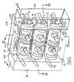
Figure 1 is a perspective view of a hydraulic power supply. -
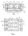
Figure 2 is a view on the line II-II ofFigure 1 . -
Figure 3 is a view on the line III-III ofFigure 3 . -
Figure 4 is a view on the line IV-IV ofFigure 1 . -
Figure 5 is an end view ofFigure 1 with portions removed for clarity. - Referring therefore to
Figure 1 , ahousing 10 contains a plurality ofhydraulic machines cylindrical swashplate assembly 24 and abarrel assembly 26 containing reciprocating axial pistons. Thebarrel assembly 26 is mounted upon ashaft 28 for rotation relative to the swashplate and a port plate 29 (fig 2 ) that connects the barrel to intake and output ports. The inclination of the swashplate relative to the axis of rotation of the shaft determines the stroke of the pistons in thebarrel assembly 26. A pair ofadjustment motors swashplate assembly 24 to adjust the angular position under the control of acontrol valve 34. - Further details of the construction of this hydraulic machine may be found in
US patent 7 402 027 . For the purpose of the present description it is sufficient to note that themotors upstanding projection 35 of theswashplate 24 and that measurement of displacement of theswashplate assembly 24 is obtained from afinger 37 that bears against the end face of theprojection 35. Thebarrel 26 carries atoothed ring 80 that provides a pick up for asensor 39 to measure rotation of thebarrel 26. - The
motors - In order to achieve a compact arrangement of machines, the
housing 10 is arranged with acentral body portion 50 having arear face 50a,side faces 50b and a front face 50c. A sealingend plate 52 is located on therear face 50a andvalve blocks opposite side faces 50b to accommodatecontrol valves 34 and associated circuitry. Thecentral body 50 also accommodates an accumulator assembly within a vertical bore 55 to provide a common supply of pressurised fluid to thecontrol valves 34. - The
central body 50 is provided with three paralleltransverse bores 60 that extend between opposite sides faces of thebody 50. Thebores 60 are dimensioned to conform to the curvature of theswashplate 24 and provide a smooth bearing surface for the swashplate. Thebores 60 may be machined in line from end to end, thereby enhancing the accuracy of the bearing surface and may incorporate a fluid bearing to support theswashplate 24. - The
transverse bores 60 are intersected bylongitudinal cavities 61 that accommodate thebarrels 26 and extend from theend face 50a. Themain body 50 also includes bearing supports 62 coaxial with thelongitudinal cavities 61 to receive the distal end of theshaft 28 and provide support therefore. Theport plates 29 are supported inrecesses 31 in thesealing plate 52 so as to bear against the end face of thebarrels 26. Bores 64 in the sealing plate are aligned withbores 62 to provide support for theshaft 28. - The
motors bore 35 that extends from theend face 50a of thebody 50 in to thetransverse bores 60. The sleeves are captured by threaded ends in to thebody 50 so as to be retained in the body and not impose significant axial loading on the joint between theend face 50a andend plate 50. - The valve blocks 54 56include
internal cavities 33 to accommodate thecontrol valve 34. The actuator for thecontrol valve 34 is located in achamber 38 formed in theblock 54 which also accommodates the control circuitry for the valve 34.The control circuitry forvalve 34 also receives input fromsensors swashplate 24 and the speed of rotation of thebarrel 26. The sensors are located in a projection 41 and project toward thebarrel assembly 26 so as to be positioned in the appropriate location upon assembly of theblocks body 50. The valve blocks 54, 56 further contain internal ducting to transfer fluid between thecontrol valve 34 and theswashplate servo motors - In order to obtain conjoint rotation of the barrels of each machine, the outer surface of each of the
barrels 26 is formed with agear 80. Thegear 80 meshes with anidler gear 82 carried by thebody 50 and in engagement with thegears 80 of four adjacent machines. Accordingly, a single drive to one of the input shafts produces conjoint rotation in the same sense for each of the machines 12- 22.Additional gears 82 are interposed between adjacent sets of barrels so that the array of machines may be increased beyond the 6 shown or may be reduced to 4 or 2 if desired. The drive may also be connected to theidler 82 to transfer the rotation in to each of the barrels. - It will be seen therefore that a simply compact arrangement of multiple hydraulic machines is obtained with ease of manufacturer and with a single input drive to facilitate installation. It will be noted particularly from
Figure 3 that assembly of the components for each machine is relatively straightforward in that the swashplate may be slid throughbores 60 and theshaft 28 andbarrel assembly 26 inserted from therear face 50a prior to attachment of thesealing block 52. The attachment of thesealing block 52 holds the port plates in location and provides a suitable location for connecting the supply and return conduits. After assembly of the rotating components, thevalve blocks bore 60 for engagement with the rotating components. The electrical control components are separated from the hydraulic fluid in thehousing 37 and are readily accessible for testing and maintenance as required. - It will also be noted that the location of the
motors valve block valve 34. Thehousing 10 thus provides an integrated support for a plurality of sets of rotating groups and avoids the need for separate discreet housings for each set. The provision of mechanical power to each of the rotating groups may be achieved in a simple and efficient manner from a single source permitting transfer of torque between each rotating group.
Claims (15)
- A hydraulic power supply system, comprising
a housing (10) arranged with a central body (50),
a pair of longitudinal cavities (61) extending from a rear face (50a) of the central body (50),
a pair of barrels (26) rotatably mounted in said pair of longitudinal cavities (61) and having axially slidable pistons bearing against a pair of swash plates (24) to reciprocate in said barrels as said barrels rotate, and
a drive to rotate said barrels (26) in the longitudinal cavities (61),
characterized by
a transverse bore (60) extending between opposite side faces (50b) of the central body (50) and intersecting each of the longitudinal cavities (61),
the pair of swash plates (24) being located in said transverse bore (60) and supported by a peripheral wall thereof. - A system according to claim 1, wherein said pair of barrels (26) are rotatably supported on a shaft (28) extending through said central body (50).
- A system according to claims 2, wherein an end plate (52) overlies said rear face (50a) and is secured thereto to support said shaft (28).
- A system according to claim 3, wherein a port plate (29) is located between said end plate (52) and said rear face (50a) in each of said longitudinal cavities (61).
- A system according to claim 4, wherein a motor (30, 32) acts on respective ones of said swashplates (24) to rotate said swashplate in said transverse bore (60) and adjust the inclination thereof relative to said barrel (26).
- A system according to claim 5, wherein said motors (32, 32) are located in bores (35) extending from said rear face (50a) to intersect said transverse bore (60).
- A system according to claim 5, wherein each of said motors (30, 32) is controlled by a valve (34) and said valves are located in a valve block (54, 56) located on each of the opposite side faces (50b) of said body (50).
- A system according to claim 7, wherein each of said valve blocks (54, 56) includes a chamber (38) to accommodate control circuitry.
- A system according to claim 8, wherein sensors (37, 39) associated with said control circuitry project from said valve block (54, 56) for interaction with respective ones of rotating groups including barrels (26) and swashplates (24).
- A system according to claim 1, wherein said drive includes a gear train (80, 82) interconnecting said barrels (26).
- A system according to claim 10, wherein said gear train includes a gear (80) associated with each barrel (26) and an idler gear (82) interposed between adjacent barrels (26).
- A system according to claim 11, wherein power is supplied to one of said shafts (28).
- A system according to claim 11, wherein power is supplied to said idler gear (82).
- A system according to claim 1, wherein a plurality of transverse bores (60) are provided in said body (50) in spaced parallel relationship and each has longitudinal cavities (61) associated therewith.
- A system according to claim 1, wherein an accumulator is formed in said body (50).
Applications Claiming Priority (2)
| Application Number | Priority Date | Filing Date | Title |
|---|---|---|---|
| US63217704P | 2004-12-01 | 2004-12-01 | |
| PCT/US2005/043588 WO2006060639A2 (en) | 2004-12-01 | 2005-12-01 | Hydraulic power supply system |
Publications (3)
| Publication Number | Publication Date |
|---|---|
| EP1828633A2 EP1828633A2 (en) | 2007-09-05 |
| EP1828633A4 EP1828633A4 (en) | 2010-11-24 |
| EP1828633B1 true EP1828633B1 (en) | 2015-08-12 |
Family
ID=36565757
Family Applications (1)
| Application Number | Title | Priority Date | Filing Date |
|---|---|---|---|
| EP05852726.8A Expired - Lifetime EP1828633B1 (en) | 2004-12-01 | 2005-12-01 | Hydraulic power supply system |
Country Status (10)
| Country | Link |
|---|---|
| US (1) | US7171808B2 (en) |
| EP (1) | EP1828633B1 (en) |
| JP (1) | JP4927754B2 (en) |
| KR (1) | KR101283632B1 (en) |
| CN (1) | CN100582437C (en) |
| AU (1) | AU2005311759B2 (en) |
| BR (1) | BRPI0518750B1 (en) |
| CA (1) | CA2587661C (en) |
| WO (1) | WO2006060639A2 (en) |
| ZA (1) | ZA200704109B (en) |
Families Citing this family (3)
| Publication number | Priority date | Publication date | Assignee | Title |
|---|---|---|---|---|
| DE102009021717A1 (en) * | 2009-05-18 | 2010-11-25 | Robert Bosch Gmbh | Hydraulic device |
| ES2508291T3 (en) * | 2010-03-19 | 2014-10-16 | Eurofilters Holding N.V. | Vacuum cleaner filter bag |
| US9670915B2 (en) * | 2014-03-27 | 2017-06-06 | Caterpillar Inc. | SBS piston pump housing assembly |
Family Cites Families (9)
| Publication number | Priority date | Publication date | Assignee | Title |
|---|---|---|---|---|
| US3190075A (en) * | 1961-05-08 | 1965-06-22 | Ebert Heinrich | Infinitely variable transmission |
| CH510216A (en) * | 1969-05-10 | 1971-07-15 | Bosch Gmbh Robert | Hydrostatic unit |
| GB1580804A (en) * | 1976-05-20 | 1980-12-03 | Massey Ferguson Services Nv | Vehicle with hydrostatic transmission |
| GB1581134A (en) * | 1976-05-20 | 1980-12-10 | Massey Ferguson Services Nv | Crawler vehicles |
| CN2221667Y (en) * | 1995-03-17 | 1996-03-06 | 王金 | Lever-type reversible plunger oil pump |
| JP3623101B2 (en) * | 1998-03-04 | 2005-02-23 | カヤバ工業株式会社 | Hydrostatic transmission system |
| JP3103534B2 (en) * | 1999-04-02 | 2000-10-30 | 川崎重工業株式会社 | Hydraulic pump |
| CN2385099Y (en) * | 1999-07-06 | 2000-06-28 | 国营金湖输油泵厂 | Small size fuel delivery pump |
| JP2002005006A (en) * | 2000-06-23 | 2002-01-09 | Yanmar Diesel Engine Co Ltd | Lubrication method of swash plate bearing in axial piston pump motor |
-
2005
- 2005-12-01 CA CA2587661A patent/CA2587661C/en not_active Expired - Fee Related
- 2005-12-01 KR KR1020077012282A patent/KR101283632B1/en not_active Expired - Fee Related
- 2005-12-01 WO PCT/US2005/043588 patent/WO2006060639A2/en not_active Ceased
- 2005-12-01 EP EP05852726.8A patent/EP1828633B1/en not_active Expired - Lifetime
- 2005-12-01 CN CN200580046338A patent/CN100582437C/en not_active Expired - Fee Related
- 2005-12-01 US US11/291,563 patent/US7171808B2/en not_active Expired - Lifetime
- 2005-12-01 BR BRPI0518750-8A patent/BRPI0518750B1/en not_active IP Right Cessation
- 2005-12-01 AU AU2005311759A patent/AU2005311759B2/en not_active Ceased
- 2005-12-01 JP JP2007544532A patent/JP4927754B2/en not_active Expired - Fee Related
-
2007
- 2007-05-21 ZA ZA200704109A patent/ZA200704109B/en unknown
Also Published As
| Publication number | Publication date |
|---|---|
| CA2587661C (en) | 2013-08-20 |
| AU2005311759A1 (en) | 2006-06-08 |
| JP2008522100A (en) | 2008-06-26 |
| WO2006060639A2 (en) | 2006-06-08 |
| CA2587661A1 (en) | 2006-06-08 |
| EP1828633A2 (en) | 2007-09-05 |
| EP1828633A4 (en) | 2010-11-24 |
| CN100582437C (en) | 2010-01-20 |
| AU2005311759B2 (en) | 2010-11-18 |
| US20060144042A1 (en) | 2006-07-06 |
| US7171808B2 (en) | 2007-02-06 |
| ZA200704109B (en) | 2008-05-28 |
| BRPI0518750B1 (en) | 2018-03-06 |
| KR20070087578A (en) | 2007-08-28 |
| BRPI0518750A2 (en) | 2008-12-02 |
| CN101198765A (en) | 2008-06-11 |
| KR101283632B1 (en) | 2013-07-05 |
| WO2006060639A3 (en) | 2007-10-25 |
| JP4927754B2 (en) | 2012-05-09 |
Similar Documents
| Publication | Publication Date | Title |
|---|---|---|
| US6494686B1 (en) | Tandem pump and interface for same | |
| US4493189A (en) | Differential flow hydraulic transmission | |
| US7588431B2 (en) | Variable capacity pump/motor | |
| KR970703504A (en) | CONTINUOUSLY VARIABLE HYDROSTATIC TRANSMISSION | |
| KR100398844B1 (en) | Continuous Variable Hydrostatic Transmission and Hydraulic Machines | |
| KR970700832A (en) | RATIO CONTROLLER FOR A HYDROSTATIC TRANSMISSION | |
| EP1748189A1 (en) | Tandem axial piston pump unit | |
| US10935117B1 (en) | Modular drive unit | |
| CA2587661C (en) | Hydraulic power supply system | |
| JP6956734B2 (en) | Variable displacement axial piston pump with fluid controlled swash plate | |
| US3830593A (en) | Hydraulic pumps with double axial pistons | |
| EP1978248B1 (en) | Pump Equipment | |
| US6793463B1 (en) | Tandem pump and interface for same | |
| US3190075A (en) | Infinitely variable transmission | |
| WO1991019902A1 (en) | Hydraulic rotary radial piston pumps | |
| JP3769387B2 (en) | Hydraulic control device | |
| JPH0562261B2 (en) | ||
| US6612222B2 (en) | Hydrostatic continuously variable transmission | |
| EP0523280A1 (en) | Hydrostatic two-way-variable-speed drive | |
| JPS5938467B2 (en) | Gear shift operation device for hydraulic transmission | |
| US4773220A (en) | Hydraulic transmission with coaxial power-take-off and motor shafts | |
| US3175502A (en) | Variable capacity hydraulic gear pump | |
| SU1041739A1 (en) | Axial-plunger controlled pump | |
| JPS61175365A (en) | Hydraulic type speed change gear | |
| JPH0776583B2 (en) | Hydrostatic continuously variable transmission |
Legal Events
| Date | Code | Title | Description |
|---|---|---|---|
| PUAI | Public reference made under article 153(3) epc to a published international application that has entered the european phase |
Free format text: ORIGINAL CODE: 0009012 |
|
| 17P | Request for examination filed |
Effective date: 20070531 |
|
| AK | Designated contracting states |
Kind code of ref document: A2 Designated state(s): AT BE BG CH CY CZ DE DK EE ES FI FR GB GR HU IE IS IT LI LT LU LV MC NL PL PT RO SE SI SK TR |
|
| AX | Request for extension of the european patent |
Extension state: AL BA HR MK YU |
|
| R17D | Deferred search report published (corrected) |
Effective date: 20071025 |
|
| RIC1 | Information provided on ipc code assigned before grant |
Ipc: F01B 3/00 20060101AFI20080130BHEP |
|
| DAX | Request for extension of the european patent (deleted) | ||
| A4 | Supplementary search report drawn up and despatched |
Effective date: 20101027 |
|
| 17Q | First examination report despatched |
Effective date: 20110707 |
|
| RAP1 | Party data changed (applicant data changed or rights of an application transferred) |
Owner name: CONCENTRIC ROCKFORD, INC |
|
| GRAP | Despatch of communication of intention to grant a patent |
Free format text: ORIGINAL CODE: EPIDOSNIGR1 |
|
| INTG | Intention to grant announced |
Effective date: 20150318 |
|
| GRAS | Grant fee paid |
Free format text: ORIGINAL CODE: EPIDOSNIGR3 |
|
| GRAA | (expected) grant |
Free format text: ORIGINAL CODE: 0009210 |
|
| AK | Designated contracting states |
Kind code of ref document: B1 Designated state(s): AT BE BG CH CY CZ DE DK EE ES FI FR GB GR HU IE IS IT LI LT LU LV MC NL PL PT RO SE SI SK TR |
|
| REG | Reference to a national code |
Ref country code: GB Ref legal event code: FG4D |
|
| REG | Reference to a national code |
Ref country code: CH Ref legal event code: EP |
|
| REG | Reference to a national code |
Ref country code: AT Ref legal event code: REF Ref document number: 742347 Country of ref document: AT Kind code of ref document: T Effective date: 20150815 |
|
| REG | Reference to a national code |
Ref country code: IE Ref legal event code: FG4D |
|
| REG | Reference to a national code |
Ref country code: DE Ref legal event code: R096 Ref document number: 602005047260 Country of ref document: DE |
|
| REG | Reference to a national code |
Ref country code: LT Ref legal event code: MG4D |
|
| REG | Reference to a national code |
Ref country code: AT Ref legal event code: MK05 Ref document number: 742347 Country of ref document: AT Kind code of ref document: T Effective date: 20150812 |
|
| REG | Reference to a national code |
Ref country code: FR Ref legal event code: PLFP Year of fee payment: 11 |
|
| REG | Reference to a national code |
Ref country code: NL Ref legal event code: MP Effective date: 20150812 |
|
| PG25 | Lapsed in a contracting state [announced via postgrant information from national office to epo] |
Ref country code: LV Free format text: LAPSE BECAUSE OF FAILURE TO SUBMIT A TRANSLATION OF THE DESCRIPTION OR TO PAY THE FEE WITHIN THE PRESCRIBED TIME-LIMIT Effective date: 20150812 Ref country code: GR Free format text: LAPSE BECAUSE OF FAILURE TO SUBMIT A TRANSLATION OF THE DESCRIPTION OR TO PAY THE FEE WITHIN THE PRESCRIBED TIME-LIMIT Effective date: 20151113 Ref country code: FI Free format text: LAPSE BECAUSE OF FAILURE TO SUBMIT A TRANSLATION OF THE DESCRIPTION OR TO PAY THE FEE WITHIN THE PRESCRIBED TIME-LIMIT Effective date: 20150812 Ref country code: LT Free format text: LAPSE BECAUSE OF FAILURE TO SUBMIT A TRANSLATION OF THE DESCRIPTION OR TO PAY THE FEE WITHIN THE PRESCRIBED TIME-LIMIT Effective date: 20150812 |
|
| PG25 | Lapsed in a contracting state [announced via postgrant information from national office to epo] |
Ref country code: PT Free format text: LAPSE BECAUSE OF FAILURE TO SUBMIT A TRANSLATION OF THE DESCRIPTION OR TO PAY THE FEE WITHIN THE PRESCRIBED TIME-LIMIT Effective date: 20151214 Ref country code: AT Free format text: LAPSE BECAUSE OF FAILURE TO SUBMIT A TRANSLATION OF THE DESCRIPTION OR TO PAY THE FEE WITHIN THE PRESCRIBED TIME-LIMIT Effective date: 20150812 Ref country code: IS Free format text: LAPSE BECAUSE OF FAILURE TO SUBMIT A TRANSLATION OF THE DESCRIPTION OR TO PAY THE FEE WITHIN THE PRESCRIBED TIME-LIMIT Effective date: 20151212 Ref country code: PL Free format text: LAPSE BECAUSE OF FAILURE TO SUBMIT A TRANSLATION OF THE DESCRIPTION OR TO PAY THE FEE WITHIN THE PRESCRIBED TIME-LIMIT Effective date: 20150812 Ref country code: ES Free format text: LAPSE BECAUSE OF FAILURE TO SUBMIT A TRANSLATION OF THE DESCRIPTION OR TO PAY THE FEE WITHIN THE PRESCRIBED TIME-LIMIT Effective date: 20150812 Ref country code: SE Free format text: LAPSE BECAUSE OF FAILURE TO SUBMIT A TRANSLATION OF THE DESCRIPTION OR TO PAY THE FEE WITHIN THE PRESCRIBED TIME-LIMIT Effective date: 20150812 |
|
| PG25 | Lapsed in a contracting state [announced via postgrant information from national office to epo] |
Ref country code: NL Free format text: LAPSE BECAUSE OF FAILURE TO SUBMIT A TRANSLATION OF THE DESCRIPTION OR TO PAY THE FEE WITHIN THE PRESCRIBED TIME-LIMIT Effective date: 20150812 |
|
| PG25 | Lapsed in a contracting state [announced via postgrant information from national office to epo] |
Ref country code: DK Free format text: LAPSE BECAUSE OF FAILURE TO SUBMIT A TRANSLATION OF THE DESCRIPTION OR TO PAY THE FEE WITHIN THE PRESCRIBED TIME-LIMIT Effective date: 20150812 Ref country code: SK Free format text: LAPSE BECAUSE OF FAILURE TO SUBMIT A TRANSLATION OF THE DESCRIPTION OR TO PAY THE FEE WITHIN THE PRESCRIBED TIME-LIMIT Effective date: 20150812 Ref country code: EE Free format text: LAPSE BECAUSE OF FAILURE TO SUBMIT A TRANSLATION OF THE DESCRIPTION OR TO PAY THE FEE WITHIN THE PRESCRIBED TIME-LIMIT Effective date: 20150812 Ref country code: CZ Free format text: LAPSE BECAUSE OF FAILURE TO SUBMIT A TRANSLATION OF THE DESCRIPTION OR TO PAY THE FEE WITHIN THE PRESCRIBED TIME-LIMIT Effective date: 20150812 |
|
| REG | Reference to a national code |
Ref country code: DE Ref legal event code: R097 Ref document number: 602005047260 Country of ref document: DE |
|
| PG25 | Lapsed in a contracting state [announced via postgrant information from national office to epo] |
Ref country code: BE Free format text: LAPSE BECAUSE OF NON-PAYMENT OF DUE FEES Effective date: 20151231 Ref country code: RO Free format text: LAPSE BECAUSE OF FAILURE TO SUBMIT A TRANSLATION OF THE DESCRIPTION OR TO PAY THE FEE WITHIN THE PRESCRIBED TIME-LIMIT Effective date: 20150812 |
|
| PLBE | No opposition filed within time limit |
Free format text: ORIGINAL CODE: 0009261 |
|
| STAA | Information on the status of an ep patent application or granted ep patent |
Free format text: STATUS: NO OPPOSITION FILED WITHIN TIME LIMIT |
|
| 26N | No opposition filed |
Effective date: 20160513 |
|
| PG25 | Lapsed in a contracting state [announced via postgrant information from national office to epo] |
Ref country code: LU Free format text: LAPSE BECAUSE OF FAILURE TO SUBMIT A TRANSLATION OF THE DESCRIPTION OR TO PAY THE FEE WITHIN THE PRESCRIBED TIME-LIMIT Effective date: 20151201 Ref country code: MC Free format text: LAPSE BECAUSE OF FAILURE TO SUBMIT A TRANSLATION OF THE DESCRIPTION OR TO PAY THE FEE WITHIN THE PRESCRIBED TIME-LIMIT Effective date: 20150812 |
|
| REG | Reference to a national code |
Ref country code: CH Ref legal event code: PL |
|
| PG25 | Lapsed in a contracting state [announced via postgrant information from national office to epo] |
Ref country code: SI Free format text: LAPSE BECAUSE OF FAILURE TO SUBMIT A TRANSLATION OF THE DESCRIPTION OR TO PAY THE FEE WITHIN THE PRESCRIBED TIME-LIMIT Effective date: 20150812 |
|
| REG | Reference to a national code |
Ref country code: IE Ref legal event code: MM4A |
|
| REG | Reference to a national code |
Ref country code: FR Ref legal event code: PLFP Year of fee payment: 12 |
|
| PG25 | Lapsed in a contracting state [announced via postgrant information from national office to epo] |
Ref country code: LI Free format text: LAPSE BECAUSE OF NON-PAYMENT OF DUE FEES Effective date: 20151231 Ref country code: IE Free format text: LAPSE BECAUSE OF NON-PAYMENT OF DUE FEES Effective date: 20151201 Ref country code: CH Free format text: LAPSE BECAUSE OF NON-PAYMENT OF DUE FEES Effective date: 20151231 |
|
| PG25 | Lapsed in a contracting state [announced via postgrant information from national office to epo] |
Ref country code: BE Free format text: LAPSE BECAUSE OF FAILURE TO SUBMIT A TRANSLATION OF THE DESCRIPTION OR TO PAY THE FEE WITHIN THE PRESCRIBED TIME-LIMIT Effective date: 20150812 |
|
| PG25 | Lapsed in a contracting state [announced via postgrant information from national office to epo] |
Ref country code: BG Free format text: LAPSE BECAUSE OF FAILURE TO SUBMIT A TRANSLATION OF THE DESCRIPTION OR TO PAY THE FEE WITHIN THE PRESCRIBED TIME-LIMIT Effective date: 20150812 Ref country code: HU Free format text: LAPSE BECAUSE OF FAILURE TO SUBMIT A TRANSLATION OF THE DESCRIPTION OR TO PAY THE FEE WITHIN THE PRESCRIBED TIME-LIMIT; INVALID AB INITIO Effective date: 20051201 |
|
| PG25 | Lapsed in a contracting state [announced via postgrant information from national office to epo] |
Ref country code: CY Free format text: LAPSE BECAUSE OF FAILURE TO SUBMIT A TRANSLATION OF THE DESCRIPTION OR TO PAY THE FEE WITHIN THE PRESCRIBED TIME-LIMIT Effective date: 20150812 |
|
| PG25 | Lapsed in a contracting state [announced via postgrant information from national office to epo] |
Ref country code: TR Free format text: LAPSE BECAUSE OF FAILURE TO SUBMIT A TRANSLATION OF THE DESCRIPTION OR TO PAY THE FEE WITHIN THE PRESCRIBED TIME-LIMIT Effective date: 20150812 |
|
| REG | Reference to a national code |
Ref country code: FR Ref legal event code: PLFP Year of fee payment: 13 |
|
| REG | Reference to a national code |
Ref country code: FR Ref legal event code: PLFP Year of fee payment: 14 |
|
| PGFP | Annual fee paid to national office [announced via postgrant information from national office to epo] |
Ref country code: FR Payment date: 20180916 Year of fee payment: 14 |
|
| PGFP | Annual fee paid to national office [announced via postgrant information from national office to epo] |
Ref country code: DE Payment date: 20180919 Year of fee payment: 14 |
|
| PGFP | Annual fee paid to national office [announced via postgrant information from national office to epo] |
Ref country code: GB Payment date: 20181001 Year of fee payment: 14 Ref country code: IT Payment date: 20181219 Year of fee payment: 14 |
|
| REG | Reference to a national code |
Ref country code: DE Ref legal event code: R119 Ref document number: 602005047260 Country of ref document: DE |
|
| GBPC | Gb: european patent ceased through non-payment of renewal fee |
Effective date: 20191201 |
|
| PG25 | Lapsed in a contracting state [announced via postgrant information from national office to epo] |
Ref country code: DE Free format text: LAPSE BECAUSE OF NON-PAYMENT OF DUE FEES Effective date: 20200701 Ref country code: IT Free format text: LAPSE BECAUSE OF NON-PAYMENT OF DUE FEES Effective date: 20191201 Ref country code: GB Free format text: LAPSE BECAUSE OF NON-PAYMENT OF DUE FEES Effective date: 20191201 Ref country code: FR Free format text: LAPSE BECAUSE OF NON-PAYMENT OF DUE FEES Effective date: 20191231 |