EP1826884A1 - Surface magnet type motor, surface magnet type motor manufacturing method, and internal combustion engine using the surface magnet type motor - Google Patents
Surface magnet type motor, surface magnet type motor manufacturing method, and internal combustion engine using the surface magnet type motor Download PDFInfo
- Publication number
- EP1826884A1 EP1826884A1 EP05803279A EP05803279A EP1826884A1 EP 1826884 A1 EP1826884 A1 EP 1826884A1 EP 05803279 A EP05803279 A EP 05803279A EP 05803279 A EP05803279 A EP 05803279A EP 1826884 A1 EP1826884 A1 EP 1826884A1
- Authority
- EP
- European Patent Office
- Prior art keywords
- magnet
- type motor
- scattering tube
- magnet type
- configuration
- Prior art date
- Legal status (The legal status is an assumption and is not a legal conclusion. Google has not performed a legal analysis and makes no representation as to the accuracy of the status listed.)
- Granted
Links
Images





Classifications
-
- H—ELECTRICITY
- H02—GENERATION; CONVERSION OR DISTRIBUTION OF ELECTRIC POWER
- H02K—DYNAMO-ELECTRIC MACHINES
- H02K15/00—Processes or apparatus specially adapted for manufacturing, assembling, maintaining or repairing of dynamo-electric machines
- H02K15/02—Processes or apparatus specially adapted for manufacturing, assembling, maintaining or repairing of dynamo-electric machines of stator or rotor bodies
- H02K15/03—Processes or apparatus specially adapted for manufacturing, assembling, maintaining or repairing of dynamo-electric machines of stator or rotor bodies having permanent magnets
-
- H—ELECTRICITY
- H02—GENERATION; CONVERSION OR DISTRIBUTION OF ELECTRIC POWER
- H02K—DYNAMO-ELECTRIC MACHINES
- H02K1/00—Details of the magnetic circuit
- H02K1/06—Details of the magnetic circuit characterised by the shape, form or construction
- H02K1/22—Rotating parts of the magnetic circuit
- H02K1/27—Rotor cores with permanent magnets
- H02K1/2706—Inner rotors
- H02K1/272—Inner rotors the magnetisation axis of the magnets being perpendicular to the rotor axis
- H02K1/2726—Inner rotors the magnetisation axis of the magnets being perpendicular to the rotor axis the rotor consisting of a single magnet or two or more axially juxtaposed single magnets
- H02K1/2733—Annular magnets
-
- Y—GENERAL TAGGING OF NEW TECHNOLOGICAL DEVELOPMENTS; GENERAL TAGGING OF CROSS-SECTIONAL TECHNOLOGIES SPANNING OVER SEVERAL SECTIONS OF THE IPC; TECHNICAL SUBJECTS COVERED BY FORMER USPC CROSS-REFERENCE ART COLLECTIONS [XRACs] AND DIGESTS
- Y10—TECHNICAL SUBJECTS COVERED BY FORMER USPC
- Y10T—TECHNICAL SUBJECTS COVERED BY FORMER US CLASSIFICATION
- Y10T29/00—Metal working
- Y10T29/49—Method of mechanical manufacture
- Y10T29/49002—Electrical device making
- Y10T29/49009—Dynamoelectric machine
- Y10T29/49012—Rotor
Definitions
- the present invention relates to a surface magnet type motor employing a magnet for the rotor, particularly to an anti-scattering tube for preventing scattering of the magnet.
- a surface magnet type motor including a rotor having a magnet arranged at the outer circumferential surface of the rotational shaft.
- This type of motor is provided with a non-magnetic anti-scattering tube at the circumference of the magnet to prevent fracture and scattering of the magnet caused by the centrifugal force when the rotor rotates at high speed.
- the anti-scattering tube of the motor is generally fixed by press-fitting the magnet into the inner cylinder of the anti-scattering tube. Accordingly, the magnet is firmly maintained with force to prevent fracture and scattering of the magnet caused by centrifugal force (for example, refer to Japanese Patent Laying-Open Nos. 2001-025193 and 2001-218403 ).
- the press-fit margin between the anti-scattering tube and magnet must be increased to hold the magnet more firmly with stronger force.
- increase of the press-fit margin induces the possibility of the magnet being fractured during the press-fitting stage into the anti-scattering tube.
- an object of the present invention is to provide a surface magnet type motor with an anti-scattering tube that reduces stress on the magnet generated by press-fitting, a fabrication method, and an internal combustion engine including the surface magnet type motor.
- a surface magnet type motor of the present invention is configured as set forth below in view of the aforementioned problem.
- a surface magnet type motor having a magnet at the surface of a rotor includes an anti-scattering tube formed in a cylindrical configuration longer in length than the magnet mounted at the rotor in an axial direction, having the magnet press-fitted therein for preventing scattering of the magnet, and a stress alleviation portion alleviating stress generated at an end of the magnet press-fitted into the anti-scattering tube.
- the surface magnet type motor of the present invention includes, at the end of the anti-scattering tube that is longer in length than the magnet, a stress alleviation portion to alleviate stress generated at the end of the magnet caused by press-fitting the magnet into the anti-scattering tube.
- a rotor can be provided in a reduced state of the stress imposed on the end of the magnet caused by press-fitting. Therefore, fracture of the magnet can be suppressed during press-fitting, during assembly of the rotor subsequent to press-fitting, or during usage as a motor.
- the stress alleviation portion of the surface magnet type motor having the structure set forth above is provided at a projection portion that is a portion of the anti-scattering tube and protruding from each of both end faces of the press-fitted magnet, taking a configuration of suppressing a displacement difference in the direction of an inner diameter generated between the projection portion and a portion excluding the projection portion by the press-fitting.
- the projection portion of the anti-scattering tube is provided with a configuration that suppresses the difference in the direction of the inner diameter.
- This is qualified as the stress alleviation portion. Specifically, the difference between the displacement in the direction of the inner diameter generated at a portion excluding the projection portion caused by press-fitting of the magnet and the displacement in the direction of the inner diameter of the projection portion that is affected by the press-fitting of the magnet into this portion is suppressed.
- significant deformation at a portion of the anti-scattering tube caused by press-fitting of the magnet can be suppressed.
- the stress imposed on the end of the magnet originating from the reactive force caused by deformation of the anti-scattering tube can be reduced.
- the stress alleviation portion of the surface magnet type motor having the structure set forth above may take a configuration of suppressing the difference by forming the projection portion in lower rigidity than the portion excluding the projection portion.
- the projection portion of the anti-scattering tube is provided with a configuration of low rigidity, which is qualified as the stress alleviation portion. Since the projection portion is of low rigidity, that portion is subject to the effect of press-fitting of the magnet to be readily deformed. In other words, the effect of the portion excluding the projection portion that is increased in diameter by the presence of a magnet inside is readily received. Therefore, the difference in displacement in the direction of the inner diameter between the projection portion and the portion excluding the projection subsequent to press-fitting of the magnet can be suppressed to reduce the stress imposed on the end of the magnet.
- the configuration of suppressing the difference at the surface magnet type motor having the structure set forth above can achieve low rigidity by forming the projection portion thinner than the portion excluding the projection portion.
- the projection portion is made thinner than the portion excluding the projection portion.
- the anti-scattering tube can be formed in, for example, a step-graded cylindrical configuration. Accordingly, the configuration of low rigidity can be realized by a relatively simply configuration to facilitate provision of a stress alleviation portion.
- the configuration of suppressing the difference at the surface magnet type motor having the structure set forth above may achieve lower rigidity by forming a notch of a predetermined depth at the outer circumference of the projection portion.
- a notch is formed at the outer circumference of the projection portion of the anti-scattering tube. Therefore, a configuration of low rigidity can be realized with a relatively simple process.
- the stress alleviation portion of the surface magnet type motor having the structure set forth above may take a configuration of suppressing the difference by a tapered configuration having the inner diameter of the projection portion increased than the inner diameter of the portion excluding the projection portion.
- the inner diameter of the projection portion is increased in a tapered manner. Specifically, there is formed in advance a configuration in which the inner diameter of the end portion of the projection portion is increased. Therefore, even if the inner diameter of the portion excluding the projection portion is increased by the press-fitting of the magnet, the difference in displacement in the direction of the inner diameter between the portions after press-fitting can be suppressed since the inner diameter of the projection portion is increased in advance. As a result, the stress imposed on the end of the magnet can be reduced.
- the stress alleviation portion of the surface magnet type motor having the structure set forth above may take a configuration of suppressing the difference by forming the projection portion in a configuration having a diameter increased conically.
- the projection portion is formed to take a configuration in which both the inner diameter and outer diameter is increased conically towards the end. Therefore, the difference in the displacement in the direction of the inner diameter between the portions following press-fitting can be suppressed by virtue of the projection portion having the diameter increased in advance. Further, a configuration of suppressing the difference in the displacement in the direction of the inner diameter can be formed without greatly reducing the rigidity of the projection portion.
- the surface magnet type motor having the structure set forth above includes an assembly flange between a bearing that is to be attached to the rotational shaft and each end plane of the magnet.
- the stress alleviation portion is provided at a contact portion where a projection portion that is a portion of the anti-scattering tube protruding from each end face of the press-fitted magnet is brought into contact with the assembly flange.
- the contact portion is formed in a configuration of suppressing the difference in displacement in the direction of the inner diameter of the anti-scattering tube following press-fitting by the external force, which is qualified as the stress alleviation portion.
- the difference in displacement in the direction of the inner diameter is suppressed. Therefore, the stress imposed on the end of the magnet can be reduced.
- the contact portion of the surface magnet type motor having the structure set forth above may take a configuration of converting the external force from the assembly flange into axial force imposed on the anti-scattering tube at the outer circumferential side than at the inner circumferential side.
- the external force transmitted to the contact portion acts as the axial force imposed on the outer circumferential side of the anti-scattering tube.
- the anti-scattering tube after press-fitting takes a configuration in which the projection portion is bent inward.
- the surface magnet type motor according to the structure set forth above may have the contact portion of the anti-scattering tube take a salient configuration formed in contact with the assembly flange at the outer circumferential side end face of the anti-scattering tube.
- a salient portion to transmit the external force to the outer circumferential side of the anti-scattering tube is formed at the contact portion of the anti-scattering tube, which is qualified as the stress alleviation portion.
- a salient configuration is provided at only the contact portion of the anti-scattering tube side. It is therefore not necessary to form the assembly flange side in a particular configuration.
- the contact portion of the assembly flange may be taken as a salient portion in contact with the outer circumference side end face of the anti-scattering tube.
- the contact portion of the assembly flange is formed in a salient configuration that transmits the external force to the outer circumference side of the anti-scattering tube, which is qualified as the stress alleviation portion.
- a salient configuration is provided only at the contact portion of the assembly flange side. Therefore, it is not necessary to form the anti-scattering tube in a particular configuration.
- the contact portion of the anti-scattering tube is formed in a cylindrical configuration smaller than the outer diameter of the portion excluding the projection portion to set the anti-scattering tube entirely in a step-graded cylindrical configuration, and forming the contact portion of the assembly flange in a configuration brought into contact with the shoulder portion of the step-graded cylindrical configuration.
- the small cylindrical portion of a step-graded cylindrical configuration is taken as the contact portion of the anti-scattering tube, and the configuration in contact with the shoulder portion is taken as the contact portion of the assembly flange.
- the axial force can be applied to the outer circumferential side of the anti-scattering tube via the shoulder to reduce the difference in the displacement in the direction of the inner diameter. As a result, the stress imposed on the end of the magnet can be reduced.
- the contact portion of the surface magnet type motor having the structure set forth above may take a configuration of converting the external force from the assembly flange into the force acting in a direction to increase the inner diameter of the projection portion.
- the external force transmitted to the contact portion acts as the force to increase the inner diameter of the projection portion of the anti-scattering tube.
- the anti-scattering tube subjected to press-fitting takes a configuration of the projection portion bent inwards.
- the contact portion of the anti-scattering tube is formed in a tapered configuration having the inner diameter of the projection portion increased than the inner diameter of the portion excluding the projection portion, and the contact portion of the assembly flange is formed in a configuration engaging with the tapered configuration.
- the contact portion of the anti-scattering tube is formed with the inner diameter increased in a tapered manner, and the contact portion of the assembly flange is formed in a configuration of engagement therewith to allow insert of the contact portion of the assembly flange into the anti-scattering tube.
- the inner diameter of the anti-scattering tube at the end is increased by the function of the tapered configuration. Therefore, the difference in displacement in the direction of the inner diameter of the anti-scattering tube caused by press-fitting of the magnet can be suppressed.
- the contact portion of the assembly flange may be formed in a cylindrical configuration having an outer diameter substantially equal to the outer diameter of the magnet, capable of being press-fitted into the projection portion of the anti-scattering tube.
- the projection portion of the anti-scattering tube is press-fitted into the assembly flange. Therefore, the inner diameter of the projection portion is increased substantially similar to the inner diameter of the portion excluding the projection portion. The difference in displacement in the direction of the inner diameter can be suppressed over the entire length of the anti-scattering tube.
- a fabrication method for a surface magnet type motor of the present invention is directed to a fabrication method of a surface magnet type motor having a magnet at the surface of a rotor, and includes: step (a) of forming an anti-scattering tube, covering the surface of the magnet of the rotor to prevent scattering of the magnet, in a cylindrical configuration longer in length than the magnet in the axial direction; and step (b) of press-fitting the magnet into the anti-scattering tube while constituting a stress alleviation portion that alleviates stress generated at an end of the magnet stored in the anti-scattering tube.
- the magnet is press-fitted into the anti-scattering tube while constituting a stress alleviation portion that alleviates the stress generated at an end of the magnet.
- the stress alleviation portion is constituted prior to press-fitting of the magnet, or in a following manner after press-fitting of the magnet.
- step (b) may include step (b1) of press-fitting the magnet into the anti-scattering tube to form a projection portion protruding from each of both end faces of the magnet, step (b2) of attaching an assembly flange to the projection portion to clamp the anti-scattering tube by the assembly flange, and step (b3) of, after step (b2), attaching a rotational shaft and bearing to the anti-scattering tube while applying axial force to the anti-scattering tube in a direction of the rotational shaft via the bearing to mount the rotor in a housing of the surface magnet type motor.
- axial force is applied to the anti-scattering tube in the direction of the rotational shaft via the bearing when the rotor is mounted in the housing. Therefore, the bending of the anti-scattering tube in the direction of the inner diameter, if caused, can be alleviated.
- step (b) may include step (b11) of press-fitting the magnet into the anti-scattering tube to form a projection portion protruding from each of both end faces of the magnet, step (b12) of attaching the assembly flange to the projection portion for fixture while applying axial force to the anti-scattering tube in the direction of the rotational shaft, and step (b13) of, after step (b12), attaching a rotational shaft and bearing to the anti-scattering tube to which axial force is applied to mount the rotor in a housing of the surface magnet type motor.
- axial force is applied to the anti-scattering tube in the direction of the rotational shaft when the assembly flange is attached to the anti-scattering tube into which the magnet is press-fitted. Therefore, improvement is established in advance in view of bending of the anti-scattering tube in the direction of the inner diameter.
- step (b) may include step (b21) of clamping the magnet by the assembly flange from both sides, step (b22) of press-fitting the magnet and the assembly flange integrally into the anti-scattering tube, and step (b23) of, after step (b22), attaching a rotational shaft and bearing to the anti-scattering tube to mount the rotor in a housing of the surface magnet type motor.
- the magnet and two assembly flanges are press-fitted integrally into the anti-scattering tube. Therefore, the rotor can be assembled efficiently with fewer steps as compared to the case where the assembly flange is press-fitted from both ends of the anti-scattering tube subjected to press-fitting of the magnet.
- step (b) may include step (b31) of clamping the magnet by the assembly flange from both sides in a state of axial force applied to the magnet in a direction of the rotational shaft, step (b32) of press-fitting the magnet in a state under application of axial force and the assembly flange integrally into the anti-scattering tube, and step (b33) of attaching a rotational shaft and bearing to the anti-scattering tube with the magnet and assembly flange to mount the rotor in a housing of the surface magnet type motor.
- axial force is applied to the magnet per se in the direction of the rotational shaft, i.e. compressive force is applied for mounting the rotor in the housing under this state.
- deformation of constriction or elongation of the magnet during the press-fitting process can be regulated, i.e. tensile stress can be suppressed, to reduce fracture of the magnet.
- step (b31) may include the step of passing an assembly bolt through the magnet and the assembly flange to apply axial force by tightening an assembly nut.
- axial force can be readily applied to the magnet per se by the tightening force of the assembly bolt and assembly nut.
- An internal combustion engine including a surface magnet type motor of the present invention is directed to an internal combustion engine including a supercharger with a turbine shaft.
- the surface magnet type motor having a magnet at the surface of a rotor is employed as a motor for assist of the turbine shaft.
- the surface magnet type motor includes an anti-scattering tube formed in a cylindrical configuration longer in length than the magnet mounted at the rotorin an axial direction, having the magnet press-fitted therein for preventing scattering of the magnet.
- the surface magnet type motor is provided with a stress alleviation portion for alleviating stress generated at an end of the magnet press-fitted into the anti-scattering tube.
- the surface magnet type motor is provided coaxially with the turbine shaft.
- the surface magnet type motor for alleviating stress generated at the end of the magnet is arranged coaxially with the turbine shaft for assist of the turbine shaft. Since the surface magnet type motor is under a state in which the stress on the magnet is alleviated, the surface magnet type motor is sufficiently durable even if great centrifugal force is applied by the rotation together with the turbine shaft that rotates at high speed.
- a supercharger including a motor for assist that can be arranged coaxially with a turbine shaft that rotates at high speed.
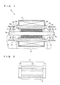
- Fig. 1 is a schematic diagram of a cross section of a first surface magnet type motor of the present invention.
- a first surface magnet type motor 10 (hereinafter, simply referred to as motor 10) is mainly formed of a rotor 15 qualified as the rotary part of motor 10, a stator 12 qualified as the stationary part of motor 10, and bearings 13 and 14 for the fixture of rotor 15 in the housing of motor 10.
- This motor 10 includes a magnet 16 for rotor 15.
- Stator 15 includes a coil for generating electromagnetic force. Rotational torque is generated by magnet 16 that repels against the electromagnetic force.
- This motor 10 is coupled with the turbine shaft of a vehicle on which a turbocharger is mounted to assist the turbine shaft (refer to Fig. 18). The rotational speed of rotor 15 becomes as high as several hundred thousands rpm.
- Rotor 15 includes, in addition to magnet 16, a rotational shaft 20 qualified as the output shaft, an anti-scattering tube 17 preventing fracture and/or scattering of magnet 16, and assembly flanges 18 and 19 between anti-scattering tube 17 and respective bearings 13 and 14.
- Rotational shaft 20 rotates at high speed together with magnet 16, anti-scattering tube 17 and assembly flanges 18 and 19.
- Magnet 16 is formed of a sintered magnet of a cylindrical configuration, receiving significant centrifugal force by the high-speed rotation.
- Anti-scattering tube 17 takes a partially cylindrical configuration, arranged at the circumference of magnet 16 to prevent fracture of magnet 16 caused by the centrifugal force effect.
- Assembly flanges 18 and 19 include cylindrical portions 18b and 19b fitting with play into the inner circumference of anti-scattering tube 17, partially cylindrical portions 18c and 19c abutting against the end face of anti-scattering tube 17 to serve as a junction with anti-scattering tube 17, and cylindrical portions 18d and 19d abutting against the inner ring of bearings 13 and 14, with inner cylindrical portions 18e and 19e having an inner diameter smaller than the inner diameter of magnet 16. Rotational shaft 20 is held by this inner cylindrical portion. Since anti-scattering tube 17 is disposed between magnet 16 and stator 12, i.e. within the rotation magnetic field, anti-scattering tube 17 is formed of a non-magnetic material that avoids effect therefrom, for example, of titanium or stainless steel.
- Rotor 15 of the structure set forth above is assembled by press-fitting magnet 16 into anti-scattering tube 17 for fixture, attaching assembly flanges 18 and 19 from both ends of anti-scattering tube 17 for fixture, and passing rotational shaft 20 therethrough.
- Fixture of magnet 16 and anti-scattering tube 17 is effected by press-fitting with a large press-fitting margin. Accordingly, the effect of centrifugal force imposed on magnet 16 due to high speed rotation is reduced.
- Fixture of anti-scattering tube 17 and assembly flanges 18 and 19 is effected by welding the junction with alignment using a jig.
- Rotational shaft 20 of the assembled rotor 15 has bearings 13 and 14 attached.
- bearings 13 and 14 a ball bearing having low rotation resistance is employed to take a structure that can withstand even high speed rotation.
- electric motor 10 is implemented.
- the current flow to the coil of stator 12 is supplied from an electric circuit (refer to Fig. 18).
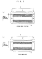
- Fig. 2 is a sectional view of a structure of anti-scattering tube 17 of the first embodiment into which magnet 16 is press-fitted.
- anti-scattering tube 17 made of titanium is formed in a step-graded cylindrical configuration longer in length than magnet 16.
- Magnet 16 is located in the proximity of approximately the center of the step-graded cylindrical configuration.
- This anti-scattering tube 17 is mainly formed of three portions, i.e. a cylinder portion 17a in which magnet 16 is present (arranged), and projection portions 17b and 17c at respective ends, protruding from respective end faces of magnet 16. Provision of projection portions 17b and 17c prevents any piece of magnet 16, when fractured, from being scattered outside.
- the inner diameter of cylinder portion 17a and projection portions 17b and 17c are the same, and made smaller than the outer diameter of magnet 16.
- a predetermined tightening margin press-fit margin
- Projection portions 17b and 17c take a cylindrical configuration thinner than cylinder portion 17a, and have rigidity lower than that of cylinder portion 17a.
- projection portions 17b and 17c are more readily deformed (elastic deformation) as compared to cylinder portion 17a.
- the outer circumference of anti-scattering tube 17 is ⁇ 30 (30 mm) with a tightening margin of 0.1 mm for the press-fitting margin.
- a press-fitting force of several tons is applied to establish the fixture between magnet 16 and anti-scattering tube 17.
- anti-scattering tube 17 receives reactive force from magnet 16 to be deformed (increased in diameter) within the elastic range.
- Cylinder portion 17a of anti-scattering tube 17 is under a state in which the diameter remains increased due to the presence of magnet 16 inside.
- Projection portions 17b and 17c are deformed, although magnet 16 is not present at the inner side, due to the low rigidity.
- projection portions 17b and 17c are also increased in inner diameter, so that the difference in the inner diameter between cylinder portion 17a and projection portions 17b and 17c subjected to press-fitting can be reduced.
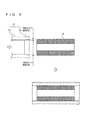
- Fig. 3 is a schematic diagram representing the difference in inner diameter after press-fitting between the different structure of a conventional case and the first embodiment.
- Fig. 3 (a) corresponds to a conventional structure whereas Fig. 3 (b) corresponds to the structure of the first embodiment.
- the broken line in the drawing represents the configuration prior to press-fitting of magnet 16.
- projection portions A2 and A3 of anti-scattering tube A of the conventional structure protruding from the end face of magnet 16 that is press-fitted, take a cylindrical configuration similar to that of cylinder portion A1 where press-fitted magnet 16 is present, and are relatively rigid. Therefore, projection portions A2 and A3 are not readily deformed, resulting an inner diameter difference D after magnet 16 is press-fitted.
- a bending moment M0 is generated at the end of magnet 16.
- projection portions 17b and 17c have an inner diameter variation greater than that of the conventional structure, resulting in an inner diameter difference d (d ⁇ D). Therefore, excessive bending stress (bending moment M0) will not be generated at the end of magnet 16 by the reactive force from projection portions 17b and 17c, seldom leading to fracture. In other words, the bending stress generated at the end of magnet 16 by press-fitting can be alleviated by virtue of the deformation of projection portions 17b and 17c of anti-scattering tube 17. As a result, fracture of magnet 16 can be suppressed during press-fitting, during attachment as rotor 15 subsequent to press-fitting, or during usage as motor 10. Further, by virtue of anti-scattering tube 17 taking a step-graded cylindrical configuration, the rigidity of projection portions 17b and 17c can be reduced. Therefore, a configuration of alleviating stress on magnet 16 can be realized by a relatively simple configuration.
- the configuration of an anti-scattering tube providing such advantages is not limited to a step-graded cylindrical configuration.
- the outer cylinder can be worked into a tapered configuration, for example, to obtain smooth transition in cross section.
- the length of the tapered portion is not particularly limited in the work of tapering, it is desirable to set the length corresponding to the length of the projection portion in view of the purpose of reducing the rigidity, as compared to a simple chamfered tapered configuration.
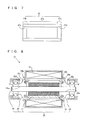
- Fig. 4 shows an example of an anti-scattering tube including a projection portion of low rigidity.
- an anti-scattering tube 27 has a cylindrical configuration substantially similar to that of anti-scattering tube 17 of Fig. 2, and differs only in the configuration of projection portions 27b and 27c protruding from the end face of press-fitted magnet 16.
- Projections 27b and 27c of anti-scattering tube 27 has a groove corresponding to a notch of a predetermined width and predetermined depth over the entire perimeter. By providing such notches, similar advantages can be provided even with projection portions 27b and 27c of low rigidity. Furthermore, projection portions 27b and 27c of low rigidity can be formed by a relatively simple process.
- the first embodiment is directed to suppressing the inner diameter difference by forming projection portions 17b and 17c in a configuration of low rigidity.
- projection portions 17b and 17c do not necessarily have to be of low rigidity.
- Fig. 5 is a sectional view of a structure of an anti-scattering tube according to a second embodiment into which magnet 16 is press-fitted.
- this anti-scattering tube 37 is formed of the three portions, i.e. a cylinder portion 37a, similar to that in the first embodiment, and projection portions 37b and 37c protruding from the end face of press-fitted magnet 16.
- Projection portions 37b and 37c are formed in a conical configuration with both the inner diameter and outer diameter gradually increased from the side of cylinder portion 37a towards the end of anti-scattering tube 37. Therefore, projection portions 37b and 37c have high rigidity as compared to cylinder portion 37a, differing from the manner in the first embodiment.
- Fig. 6 is a schematic diagram representing a manner of magnet 16 press-fitted into anti-scattering tube 37 of the second embodiment.
- cylinder portion 37a exhibits a significant inner diameter variation due to the presence of magnet 16 inside, likewise the first embodiment.
- the inner diameter variation of projection portions 37b and 37c becomes smaller since the effect of cylinder portion 37a is smaller by virtue of its high rigidity.
- Fig. 6 represents that the inner diameter of cylinder portion 37a subjected to press-fitting becomes substantially equal to the inner diameter of projection portions 37b and 37c subjected to press-fitting.
- the projection portion may take the contour configuration shown in Fig. 7, for example, corresponding to a structure in which the inner diameter is increased in advance.
- An anti-scattering tube 47 shown in the drawing is formed of a three portions, likewise the first embodiment, all taking a cylindrical configuration having the same outer diameter. Cylinder portion 47a among these three portions has an inner diameter identical to that of the first embodiment. It is to be noted that the inner diameter of projection portions 47b and 47c protruding from the end face of press-fitted magnet 16 is set to correspond to a tapered configuration 47d gradually increased in diameter from the side of cylinder portion 47a towards the outer side.
- Projection portions 47b and 47c have a tapered configuration 47d along the entire length thereof, differing from the tapered configuration provided for positioning in a press-fitting mode.
- Fig. 8 is a schematic diagram of a second surface magnet type motor of the present invention.
- a second surface magnet type motor 21 (hereinafter, simply referred to as motor 21) has a structure basically similar to that of first surface magnet type motor 10 shown in Fig. 1, provided that a rotor 25 differs. Therefore, the remaining elements have reference characters identical to those of Fig. 1 allotted, and description thereof will not be repeated.
- a rotor 25 is mainly formed of a rotational shaft 20 similar to that of first motor 10, a magnet 16, an anti-scattering tube 17, and assembly flanges 28 and 29.
- Assembly flanges 28 and 29 include, likewise assembly flanges 18 and 19 of first motor 10, cylindrical portions 28b and 29b fitting inside anti-scattering tube 17, cylindrical portions 28d and 29d abutting against the inner ring of bearings 13 and 14, and contact portions 28c and 29c of a particular configuration in contact with anti-scattering tube 17.
- Inside assembly flanges 28 and 29 are provided inner cylindrical portions 28e and 29e having an inner diameter larger than that of assembly flanges 18 and 19 of the first embodiment. In other words, assembly flanges 28 and 29 form contact with rotational shaft 20 in a slidable manner in the axial direction.
- Alignment of assembly flanges 28 and 29 with anti-scattering tube 17 is effected by cylindrical portions 28b and 29b.
- Portions 28c and 29c of a particular configuration for assembly flanges 28 and 29 will be described afterwards as the contact portion structure of assembly flanges 28 and 29.
- FIG. 9 is a process chart of assembly steps of rotor 25 corresponding to a fabrication method of motor 21.
- magnet 16 is press-fitted into anti-scattering tube 17 (step S900). Then, anti-scattering tube 17 with magnet 16 is clamped at both ends by assembly flanges 28 and 29, and rotational shaft 20 is attached (step S910).
- bearings 13 and 14 are fitted to rotational shaft 20.
- Axial force F is applied to assembly flanges 28 and 29 in the direction of rotational shaft 20 via bearings 13 and 14.
- the intact motor 21 with stator 12 is fixed in a housing (step S920) to complete assembly of rotor 25.
- predetermined steps are carried out to complete motor 21. Since assembly flanges 28 and 29 of rotor 25 assembled in accordance with these procedures are in contact with the inner ring of bearings 13 and 14, magnet 16, anti-scattering tube 17, assembly flanges 28 and 29, and rotational shaft 20 rotate integrally.
- the inner ring of bearings 13 and 14 and assembly flanges 28 and 29 are fixed by a whirl-stop not shown.
- Fig. 10 is a sectional view representing a portion of this contact portion in an enlarged manner.
- assembly flange 28 includes a salient 28a having an outer diameter substantially equal to that of anti-scattering tube 17.
- Anti-scattering tube 17 includes a shoulder 17d at the stepped portion of the cylindrical perimeter as a result of forming projection portion 17b in a step-graded cylindrical configuration.
- the contact portion of the first embodiment is configured such that salient 28a is in contact with shoulder 17d, and assembly flange 28 is not directly in contact with the end face of projection portion 17b.
- a contact portion is also provided at the bearing 14 side, symmetrical to the portion at the bearing 13 side shown in Fig. 10.
- Assembly flange 28 and anti-scattering tube 17 (including magnet 16) corresponding to the contact portion structure set forth above has an externally applied axial force F (compression force) during the assembly stage.
- the applied axial force F is transmitted as axial force F in the proximity of the outer circumference of anti-scattering tube 17 via salient 28a of assembly flange 28 (refer to the arrow in Fig. 10).
- Axial force F imposed in the proximity of the outer circumference of anti-scattering tube 17 acts as moment M1 that spreads the inner cylindrical portion of anti-scattering tube 17. This moment M1 works in a direction to reduce bending moment M0 generated at projection portions 17b and 17c of anti-scattering tube 17 caused by press-fitting of magnet 16.
- a force acts in a direction to improve the bending of anti-scattering tube A corresponding to projection portions A2 and A3 bending inwards by press-fitting. Therefore, in addition to the advantage by the configuration of projection portions 17b and 17c described in the first embodiment with reference to Fig. 3 (b), the difference in the inner diameter displacement of anti-scattering tube 17 can be further reduced to alleviate the bending stress on magnet 16.
- a contact portion may take any structure as long as the applied axial force F acts in a direction to reduce bending moment M0 (refer to Fig. 3) generated at the anti-scattering tube.
- Other structures of such a contact portion is shown hereinafter.
- Fig. 11 is a partial sectional view of a structure of a contact portion of the assembly flange and anti-scattering tube according to the second embodiment. Although only the bearing 13 side is indicated as the contact portion structure in Fig. 11, a contact portion structure symmetric to the bearing 13 side is provided at the bearing 14 side, likewise Fig. 10.
- the contact portion of anti-scattering tube 57 includes a salient 57a protruding in the axial direction in the proximity of the outer circumference at both ends of the cylindrical configuration.
- the contact portion of assembly flange 38 includes a flat face 38a.
- Externally applied axial force F acts as axial force f (refer to the arrow in Fig. 11) on salient 57a of anti-scattering tube 57 via the inner ring of bearing 13 and flat face 38a of assembly flange 38. Therefore, likewise first embodiment, bending moment M0 generated at anti-scattering tube 57 is reduced to suppress the inner diameter displacement difference by axial force f applied in the proximity of the outer circumference of anti-scattering tube 57. Therefore, the bending stress on magnet 16 can be alleviated.
- Salient 57a provided only on the part of anti-scattering tube 57 may be provided only on the part of assembly flange 48, as shown in Fig. 12. In this case, a salient 48a is provided at assembly flange 48, as shown in the drawing. It is not necessary to provide a particular configuration for the anti-scattering tube, as compared to the structure shown in Fig. 10.
- Fig. 13 is a partial sectional view of a structure of a contact portion of the assembly flange and anti-scattering tube according to a third embodiment. Although only the bearing 13 side is indicated as the contact portion structure in Fig. 13, a contact portion structure symmetric to the bearing 13 side is provided at the bearing 14 side, likewise Fig. 10.
- the contact portion of anti-scattering tube 67 includes a tapered portion 67a having the inner diameter increased in the direction from the end face of magnet 16 to the end face of anti-scattering tube 67.
- the contact portion of assembly flange 58 includes an engagement portion 58a engaging with and longer than tapered portion 67a.
- engagement portion 58a of assembly flange 58 takes a structure to be inserted into anti-scattering tube 67 to form contact.
- Externally applied axial force F causes engagement portion 58a of assembly flange 58 to wedge into anti-scattering tube 67, i.e. by the wedge effect, to increase the inner diameter of anti-scattering tube 67 at the end face.
- the structure converts axial force F into force P acting in the direction to increase the diameter.
- the difference in inner diameter displacement of anti-scattering tube 67 is reduced to alleviate the bending stress on magnet 16.
- the alignment between assembly flange 58 and anti-scattering tube 67 is facilitated by virtue of the wedge effect.
- axial force F is applied during the mounting stage to the housing, which reduces the difference in the inner diameter variation caused by press-fitting into the anti-scattering tube to reduce the bending stress on magnet 16. Therefore, bending at the anti-scattering tube, even if occurred prior to mounting in the housing, can be improved by axial force F.
- the step of applying axial force F may be conducted prior to mounting in the housing, i.e. assembly may be first conducted while applying axial force F to the anti-scattering tube and the assembly flange.
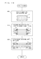
- Fig. 14 is a process chart of assembly steps of rotor 25 corresponding to the fabrication method of motor 21.
- magnet 16 is press-fitted into anti-scattering tube 17 (step S400).
- anti-scattering tube 17 with magnet 16 is clamped by assembly flanges 28 and 29 at both ends, and assembly flanges 28 and 29 and anti-scattering tube 17 are welded for fixture while axial force F is applied from both ends (step S410).
- Rotational shaft 20 and bearings 13 and 14 are attached to the assembly under a state where internal compression stress remains, and mounted in the housing (step S420) to complete the assembly of rotor 25.
- the advantage of reducing the bending stress on magnet 16 can be provided even in the case where the step of applying axial force F is conducted prior to mounting in the housing. Further, the bending of the anti-scattering tube can be improved in advance.
- the third embodiment (Fig. 13) of second motor 21 of the present invention is based on a structure in which the inner diameter of anti-scattering tube 67 is increased at the end face taking advantage of the tapered configuration.
- a flat configuration may be employed instead of the inclination of the tapered configuration.
- the portion of assembly flange wedged into the anti-scattering tube may take a simple cylindrical configuration. This structure will be described hereinafter.
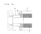
- Fig. 15 is a partial sectional view of a structure of a modification of the contact portion of the assembly flange and anti-scattering tube.
- the contact portion of assembly flange 68 includes a cylinder portion 68a having an outer diameter substantially equal to that of magnet 16.
- the contact portion of anti-scattering tube 77 has no particular structure provided, remaining in the cylindrical configuration with the press-fit margin for allowing magnet 16 to be press-fitted.
- Figs. 11 and 13 only the structure on the part of bearing 13 is indicated in this modification, and the structure on the part of bearing 14 is not shown.
- press-fitting force FA is applied to assembly flange 68 as externally applied axial force F.
- the press-fit force FA causes cylinder portion 68a of assembly flange 68 to be pushed in to be located at both ends of anti-scattering tube 77.
- force P acts in a direction to increase the inner diameter of anti-scattering tube 77 at the end by the press-fitting of assembly flange 68, whereby the displacement difference in the direction of the inner diameter can be suppressed over the entire length of anti-scattering tube 77. Therefore, the bending stress on magnet 16 can be alleviated.
- Fig. 16 is a process chart of assembly steps of a rotor having the contact portion structure shown in Fig. 15. As shown in the drawing, magnet 16 is clamped at both ends by assembly flanges 68 and 69 (step S600). The clamp through assembly flanges 68 and 69 is favorably conducted to form a unitary piece by means of a jig, adhesive, or the like.
- step S610 the assembly with assembly flanges 68 and 69 and magnet 16 together is press-fitted into anti-scattering tube 77 (step S610.)
- magnet 16 is located up to the end of anti-scattering tube 77.
- the inner diameter of anti-scattering tube 77 at the end is increased in diameter, similar to the portion having magnet 16 disposed inside.
- Rotational shaft 20 is inserted into the inner cylindrical portion of assembly flanges 68 and 69 and magnet 16 fastened with anti-scattering tube 77, and mounted in the housing together with bearings 13 and 14 (step S620) to complete the assembly of the rotor.
- the rotor can be assembled with one press-fitting step without having to apply the press-fitting force repeatedly. Therefore, an efficient fabrication method of a rotor having the number of steps reduced can be realized.
- Fig. 17 is a process chart of the assembly steps of a rotor having the contact portion structure shown in Fig. 15. As shown in the drawing, an assembly bolt 90 is inserted through assembly flanges 68 and 69, tightened by an assembly nut 91 to clamp assembly flanges 68 and 69 under a state with compression force applied to magnet 16 by the tightening force (step S700).
- step S710 The integrated assembly is press-fitted into anti-scattering tube 77 and secured (step S710). At this step, assembly flanges 68 and 69 and magnet 16 in a state having compression force applied are fixed with anti-scattering tube 77.
- step S720 assembly bolt 90 and assembly nut 91 are removed from magnetic 16 and assembly flanges 68 and 69 that are fixed by press-fitting, and rotational shaft 20 is inserted to be mounted together with bearings 13 and 14 in the housing.
- step S720 assembly bolt 90 and assembly nut 91 are removed from magnetic 16 and assembly flanges 68 and 69 that are fixed by press-fitting, and rotational shaft 20 is inserted to be mounted together with bearings 13 and 14 in the housing.
- the displacement difference in the direction of the inner diameter of anti-scattering tube 77 is reduced to alleviate the bending stress on magnet 16. Further, by applying the compression force to magnet 16 per se, the bending stress acting all over magnet 16 (the tensile stress by bending) can be suppressed.
- Fig. 18 is a schematic diagram of a system including a surface magnet type motor for an engine that includes a turbocharger as the supercharger.
- this system is mainly configured of an engine 100 including an inlet pipe 101 and an exhaust pipe 102, a turbocharger 110 including a wheel in inlet pipe 101 and exhaust pipe 102, a surface magnet type motor 120 arranged coaxially with turbocharger 110, an inverter 130, and an ECU 140 providing control of the entire system such as for engine 100, turbocharger 110, and the like.
- Surface magnet type motor 120 herein may be first motor 10 or second motor 21.
- the energy of the exhaust output from engine 100 causes rotation of the turbine wheel that is the wheel at the exhaust pipe 102 side.
- the compressor wheel that is the wheel at the exhaust pipe 101 side is rotated. Accordingly, compressed air can be supplied to engine 100 to improve the charging efficiency.
- the turbine shaft that couples the turbine wheel and the compressor wheel is forced to rotate when the energy of the exhaust is not sufficient.
- the electric power to surface magnet type motor 120 is supplied via inverter 130 under control of ECU 140.
- a bypass with respect to the turbine wheel is provided at exhaust pipe 102.
- a waste gate valve 115 is arranged in the proximity of the entrance of the bypass. In the case where supercharging is not required, control to open waste gate valve 115 is effected.
- a system including a motor employed in the assist of a turbine shaft that requires high speed rotation a system having the motor arranged on a shaft different from the turbine shaft for transmitting power to the turbine shaft, or a system that has a one way clutch installed to prevent the following rotation of the turbine shaft can be assumed.
- the allowable rotation speed of the motor can be suppressed at a low level by employing such a system.
- the surface magnet type motor of the present invention can accommodate high speed rotation, and can be arranged coaxial to the turbine shaft for the assist of the turbine shaft.
- the surface magnet type motor of the present invention can accommodate relatively readily a system in which high speed rotation is required.
Landscapes
- Engineering & Computer Science (AREA)
- Power Engineering (AREA)
- Manufacturing & Machinery (AREA)
- Permanent Field Magnets Of Synchronous Machinery (AREA)
Abstract
Description
- The present invention relates to a surface magnet type motor employing a magnet for the rotor, particularly to an anti-scattering tube for preventing scattering of the magnet.
- Conventionally, there is known a surface magnet type motor including a rotor having a magnet arranged at the outer circumferential surface of the rotational shaft. This type of motor is provided with a non-magnetic anti-scattering tube at the circumference of the magnet to prevent fracture and scattering of the magnet caused by the centrifugal force when the rotor rotates at high speed.
- The anti-scattering tube of the motor is generally fixed by press-fitting the magnet into the inner cylinder of the anti-scattering tube. Accordingly, the magnet is firmly maintained with force to prevent fracture and scattering of the magnet caused by centrifugal force (for example, refer to
Japanese Patent Laying-Open Nos. 2001-025193 2001-218403 - In order to realize usage under a high centrifugal force in a wide range of operating temperature to accommodate higher speed rotation of a motor having such a structure, the press-fit margin between the anti-scattering tube and magnet must be increased to hold the magnet more firmly with stronger force. However, increase of the press-fit margin induces the possibility of the magnet being fractured during the press-fitting stage into the anti-scattering tube.
- Even if the event of fracture does not occur at the time of assembly, such stress on the magnet may result in fracture during operation of the surface magnet type motor by the effect of the centrifugal force. Particularly in the case where such a motor is employed for the assist of the turbine shaft of a turbocharger that rotates as fast as one hundred and several ten thousands to two hundred and several ten thousands rpm, the strength as high as the operation limit of the turbine shaft must be ensured. Thus, the need arises for a structure and/or fabrication method that alleviates the stress on the magnet.
- In view of the problems set forth above, an object of the present invention is to provide a surface magnet type motor with an anti-scattering tube that reduces stress on the magnet generated by press-fitting, a fabrication method, and an internal combustion engine including the surface magnet type motor.
- A surface magnet type motor of the present invention is configured as set forth below in view of the aforementioned problem. A surface magnet type motor having a magnet at the surface of a rotor includes an anti-scattering tube formed in a cylindrical configuration longer in length than the magnet mounted at the rotor in an axial direction, having the magnet press-fitted therein for preventing scattering of the magnet, and a stress alleviation portion alleviating stress generated at an end of the magnet press-fitted into the anti-scattering tube.
- The surface magnet type motor of the present invention includes, at the end of the anti-scattering tube that is longer in length than the magnet, a stress alleviation portion to alleviate stress generated at the end of the magnet caused by press-fitting the magnet into the anti-scattering tube. Specifically, a rotor can be provided in a reduced state of the stress imposed on the end of the magnet caused by press-fitting. Therefore, fracture of the magnet can be suppressed during press-fitting, during assembly of the rotor subsequent to press-fitting, or during usage as a motor.
- The stress alleviation portion of the surface magnet type motor having the structure set forth above is provided at a projection portion that is a portion of the anti-scattering tube and protruding from each of both end faces of the press-fitted magnet, taking a configuration of suppressing a displacement difference in the direction of an inner diameter generated between the projection portion and a portion excluding the projection portion by the press-fitting.
- According to the surface magnet type motor, the projection portion of the anti-scattering tube is provided with a configuration that suppresses the difference in the direction of the inner diameter. This is qualified as the stress alleviation portion. Specifically, the difference between the displacement in the direction of the inner diameter generated at a portion excluding the projection portion caused by press-fitting of the magnet and the displacement in the direction of the inner diameter of the projection portion that is affected by the press-fitting of the magnet into this portion is suppressed. Thus, significant deformation at a portion of the anti-scattering tube caused by press-fitting of the magnet can be suppressed. As a result, the stress imposed on the end of the magnet originating from the reactive force caused by deformation of the anti-scattering tube can be reduced.
- The stress alleviation portion of the surface magnet type motor having the structure set forth above may take a configuration of suppressing the difference by forming the projection portion in lower rigidity than the portion excluding the projection portion.
- According to the surface magnet type motor, the projection portion of the anti-scattering tube is provided with a configuration of low rigidity, which is qualified as the stress alleviation portion. Since the projection portion is of low rigidity, that portion is subject to the effect of press-fitting of the magnet to be readily deformed. In other words, the effect of the portion excluding the projection portion that is increased in diameter by the presence of a magnet inside is readily received. Therefore, the difference in displacement in the direction of the inner diameter between the projection portion and the portion excluding the projection subsequent to press-fitting of the magnet can be suppressed to reduce the stress imposed on the end of the magnet.
- The configuration of suppressing the difference at the surface magnet type motor having the structure set forth above can achieve low rigidity by forming the projection portion thinner than the portion excluding the projection portion.
- According to the surface magnet type motor, the projection portion is made thinner than the portion excluding the projection portion. For the thin configuration, the anti-scattering tube can be formed in, for example, a step-graded cylindrical configuration. Accordingly, the configuration of low rigidity can be realized by a relatively simply configuration to facilitate provision of a stress alleviation portion.
- The configuration of suppressing the difference at the surface magnet type motor having the structure set forth above may achieve lower rigidity by forming a notch of a predetermined depth at the outer circumference of the projection portion.
- According to the surface magnet type motor, a notch is formed at the outer circumference of the projection portion of the anti-scattering tube. Therefore, a configuration of low rigidity can be realized with a relatively simple process.
- The stress alleviation portion of the surface magnet type motor having the structure set forth above may take a configuration of suppressing the difference by a tapered configuration having the inner diameter of the projection portion increased than the inner diameter of the portion excluding the projection portion.
- According to the surface magnet type motor, the inner diameter of the projection portion is increased in a tapered manner. Specifically, there is formed in advance a configuration in which the inner diameter of the end portion of the projection portion is increased. Therefore, even if the inner diameter of the portion excluding the projection portion is increased by the press-fitting of the magnet, the difference in displacement in the direction of the inner diameter between the portions after press-fitting can be suppressed since the inner diameter of the projection portion is increased in advance. As a result, the stress imposed on the end of the magnet can be reduced.
- The stress alleviation portion of the surface magnet type motor having the structure set forth above may take a configuration of suppressing the difference by forming the projection portion in a configuration having a diameter increased conically.
- In accordance with the surface magnet type motor, the projection portion is formed to take a configuration in which both the inner diameter and outer diameter is increased conically towards the end. Therefore, the difference in the displacement in the direction of the inner diameter between the portions following press-fitting can be suppressed by virtue of the projection portion having the diameter increased in advance. Further, a configuration of suppressing the difference in the displacement in the direction of the inner diameter can be formed without greatly reducing the rigidity of the projection portion.
- The surface magnet type motor having the structure set forth above includes an assembly flange between a bearing that is to be attached to the rotational shaft and each end plane of the magnet. The stress alleviation portion is provided at a contact portion where a projection portion that is a portion of the anti-scattering tube protruding from each end face of the press-fitted magnet is brought into contact with the assembly flange. There can be provided a configuration of suppressing the displacement difference in the direction of the inner diameter generated between the projection portion and a portion excluding the projection portion by press-fitting through application of external force in a direction of the rotational shaft from both outer sides of the assembly flange.
- According to the surface magnet type motor, the contact portion is formed in a configuration of suppressing the difference in displacement in the direction of the inner diameter of the anti-scattering tube following press-fitting by the external force, which is qualified as the stress alleviation portion. In other words, by applying external force from both outer sides of the assembly flange to the anti-scattering tube where a displacement difference in the direction of the inner diameter is already generated by press-fitting of the magnet, the difference in displacement in the direction of the inner diameter is suppressed. Therefore, the stress imposed on the end of the magnet can be reduced.
- The contact portion of the surface magnet type motor having the structure set forth above may take a configuration of converting the external force from the assembly flange into axial force imposed on the anti-scattering tube at the outer circumferential side than at the inner circumferential side.
- According to the surface magnet type motor, the external force transmitted to the contact portion acts as the axial force imposed on the outer circumferential side of the anti-scattering tube. For example, when the inner diameter variation of the projection portion caused by press-fitting of the magnet is smaller than the inner diameter variation of the portion excluding the projection portion, the anti-scattering tube after press-fitting takes a configuration in which the projection portion is bent inward. By applying axial force to the outer circumferential side of the anti-scattering tube, force acts in a direction to improve the inward bending to suppress the difference in displacement in the direction of the inner diameter.
- The surface magnet type motor according to the structure set forth above may have the contact portion of the anti-scattering tube take a salient configuration formed in contact with the assembly flange at the outer circumferential side end face of the anti-scattering tube.
- According to the surface magnet type motor, a salient portion to transmit the external force to the outer circumferential side of the anti-scattering tube is formed at the contact portion of the anti-scattering tube, which is qualified as the stress alleviation portion. In other words, a salient configuration is provided at only the contact portion of the anti-scattering tube side. It is therefore not necessary to form the assembly flange side in a particular configuration.
- In the surface magnet type motor having the structure set forth above, the contact portion of the assembly flange may be taken as a salient portion in contact with the outer circumference side end face of the anti-scattering tube.
- According to the surface magnet type motor, the contact portion of the assembly flange is formed in a salient configuration that transmits the external force to the outer circumference side of the anti-scattering tube, which is qualified as the stress alleviation portion. In other words, a salient configuration is provided only at the contact portion of the assembly flange side. Therefore, it is not necessary to form the anti-scattering tube in a particular configuration.
- In the surface magnet type motor having the structure set forth above, the contact portion of the anti-scattering tube is formed in a cylindrical configuration smaller than the outer diameter of the portion excluding the projection portion to set the anti-scattering tube entirely in a step-graded cylindrical configuration, and forming the contact portion of the assembly flange in a configuration brought into contact with the shoulder portion of the step-graded cylindrical configuration.
- According to the surface magnet type motor, the small cylindrical portion of a step-graded cylindrical configuration is taken as the contact portion of the anti-scattering tube, and the configuration in contact with the shoulder portion is taken as the contact portion of the assembly flange. In addition to the advantage of reducing the rigidity, the axial force can be applied to the outer circumferential side of the anti-scattering tube via the shoulder to reduce the difference in the displacement in the direction of the inner diameter. As a result, the stress imposed on the end of the magnet can be reduced.
- The contact portion of the surface magnet type motor having the structure set forth above may take a configuration of converting the external force from the assembly flange into the force acting in a direction to increase the inner diameter of the projection portion.
- According to the surface magnet type motor, the external force transmitted to the contact portion acts as the force to increase the inner diameter of the projection portion of the anti-scattering tube. For example, when the inner diameter variation of the projection portion caused by the press-fitting of the magnet is smaller than the inner diameter variation of the portion excluding the projection portion, the anti-scattering tube subjected to press-fitting takes a configuration of the projection portion bent inwards. By applying external force to this anti-scattering tube, the inner diameter of the projection portion can be increased to suppress the difference in displacement in the direction of the inner diameter.
- In the surface magnet type motor having the structure set forth above, the contact portion of the anti-scattering tube is formed in a tapered configuration having the inner diameter of the projection portion increased than the inner diameter of the portion excluding the projection portion, and the contact portion of the assembly flange is formed in a configuration engaging with the tapered configuration.
- According to the surface magnet type motor, the contact portion of the anti-scattering tube is formed with the inner diameter increased in a tapered manner, and the contact portion of the assembly flange is formed in a configuration of engagement therewith to allow insert of the contact portion of the assembly flange into the anti-scattering tube. By the externally applied external force of the assembly flange having such a contact portion, the inner diameter of the anti-scattering tube at the end is increased by the function of the tapered configuration. Therefore, the difference in displacement in the direction of the inner diameter of the anti-scattering tube caused by press-fitting of the magnet can be suppressed.
- In the surface magnet type motor having the structure set forth above, the contact portion of the assembly flange may be formed in a cylindrical configuration having an outer diameter substantially equal to the outer diameter of the magnet, capable of being press-fitted into the projection portion of the anti-scattering tube.
- According to the surface magnet type motor, the projection portion of the anti-scattering tube is press-fitted into the assembly flange. Therefore, the inner diameter of the projection portion is increased substantially similar to the inner diameter of the portion excluding the projection portion. The difference in displacement in the direction of the inner diameter can be suppressed over the entire length of the anti-scattering tube.
- A fabrication method for a surface magnet type motor of the present invention is directed to a fabrication method of a surface magnet type motor having a magnet at the surface of a rotor, and includes: step (a) of forming an anti-scattering tube, covering the surface of the magnet of the rotor to prevent scattering of the magnet, in a cylindrical configuration longer in length than the magnet in the axial direction; and step (b) of press-fitting the magnet into the anti-scattering tube while constituting a stress alleviation portion that alleviates stress generated at an end of the magnet stored in the anti-scattering tube.
- According to the fabrication method, the magnet is press-fitted into the anti-scattering tube while constituting a stress alleviation portion that alleviates the stress generated at an end of the magnet. The stress alleviation portion is constituted prior to press-fitting of the magnet, or in a following manner after press-fitting of the magnet. Thus, a fabrication method is provided that alleviates stress generated at the magnet to suppress fracture thereof.
- In the fabrication method of a surface magnet type motor based on the steps set forth above, step (b) may include step (b1) of press-fitting the magnet into the anti-scattering tube to form a projection portion protruding from each of both end faces of the magnet, step (b2) of attaching an assembly flange to the projection portion to clamp the anti-scattering tube by the assembly flange, and step (b3) of, after step (b2), attaching a rotational shaft and bearing to the anti-scattering tube while applying axial force to the anti-scattering tube in a direction of the rotational shaft via the bearing to mount the rotor in a housing of the surface magnet type motor.
- According to the fabrication method, axial force is applied to the anti-scattering tube in the direction of the rotational shaft via the bearing when the rotor is mounted in the housing. Therefore, the bending of the anti-scattering tube in the direction of the inner diameter, if caused, can be alleviated.
- In the fabrication method of a surface magnet type motor based on the steps set forth above, step (b) may include step (b11) of press-fitting the magnet into the anti-scattering tube to form a projection portion protruding from each of both end faces of the magnet, step (b12) of attaching the assembly flange to the projection portion for fixture while applying axial force to the anti-scattering tube in the direction of the rotational shaft, and step (b13) of, after step (b12), attaching a rotational shaft and bearing to the anti-scattering tube to which axial force is applied to mount the rotor in a housing of the surface magnet type motor.
- According to the fabrication method, axial force is applied to the anti-scattering tube in the direction of the rotational shaft when the assembly flange is attached to the anti-scattering tube into which the magnet is press-fitted. Therefore, improvement is established in advance in view of bending of the anti-scattering tube in the direction of the inner diameter.
- In the fabrication method of a surface magnet type motor based on the steps set forth above, step (b) may include step (b21) of clamping the magnet by the assembly flange from both sides, step (b22) of press-fitting the magnet and the assembly flange integrally into the anti-scattering tube, and step (b23) of, after step (b22), attaching a rotational shaft and bearing to the anti-scattering tube to mount the rotor in a housing of the surface magnet type motor.
- According to the fabrication method, the magnet and two assembly flanges are press-fitted integrally into the anti-scattering tube. Therefore, the rotor can be assembled efficiently with fewer steps as compared to the case where the assembly flange is press-fitted from both ends of the anti-scattering tube subjected to press-fitting of the magnet.
- In the fabrication method of a surface magnet type motor based on the steps set forth above, step (b) may include step (b31) of clamping the magnet by the assembly flange from both sides in a state of axial force applied to the magnet in a direction of the rotational shaft, step (b32) of press-fitting the magnet in a state under application of axial force and the assembly flange integrally into the anti-scattering tube, and step (b33) of attaching a rotational shaft and bearing to the anti-scattering tube with the magnet and assembly flange to mount the rotor in a housing of the surface magnet type motor.
- According to the fabrication method, axial force is applied to the magnet per se in the direction of the rotational shaft, i.e. compressive force is applied for mounting the rotor in the housing under this state. In addition to the advantage of the third fabrication method, deformation of constriction or elongation of the magnet during the press-fitting process can be regulated, i.e. tensile stress can be suppressed, to reduce fracture of the magnet.
- In the fabrication method of a surface magnet type motor based on the steps set forth above, step (b31) may include the step of passing an assembly bolt through the magnet and the assembly flange to apply axial force by tightening an assembly nut.
- In accordance with the fabrication method, axial force can be readily applied to the magnet per se by the tightening force of the assembly bolt and assembly nut.
- An internal combustion engine including a surface magnet type motor of the present invention is directed to an internal combustion engine including a supercharger with a turbine shaft. The surface magnet type motor having a magnet at the surface of a rotor is employed as a motor for assist of the turbine shaft. The surface magnet type motor includes an anti-scattering tube formed in a cylindrical configuration longer in length than the magnet mounted at the rotorin an axial direction, having the magnet press-fitted therein for preventing scattering of the magnet. The surface magnet type motor is provided with a stress alleviation portion for alleviating stress generated at an end of the magnet press-fitted into the anti-scattering tube. The surface magnet type motor is provided coaxially with the turbine shaft.
- According to the internal combustion engine of the present invention, the surface magnet type motor for alleviating stress generated at the end of the magnet is arranged coaxially with the turbine shaft for assist of the turbine shaft. Since the surface magnet type motor is under a state in which the stress on the magnet is alleviated, the surface magnet type motor is sufficiently durable even if great centrifugal force is applied by the rotation together with the turbine shaft that rotates at high speed. There can be provided an internal combustion engine with a supercharger including a motor for assist that can be arranged coaxially with a turbine shaft that rotates at high speed.
-
- Fig. 1 is a schematic diagram of a cross section of a first surface magnet type motor of the present invention.
- Fig. 2 is a sectional view of a structure of an anti-scattering tube of a first embodiment.
- Fig. 3 is a schematic diagram representing the difference in inner diameter after press-fitting between the different structure of a conventional case and the first embodiment.
- Fig. 4 is a sectional view of an example of an anti-scattering tube.
- Fig. 5 is a sectional view of a structure of an anti-scattering tube according to a second embodiment.
- Fig. 6 is a schematic diagram representing a manner of a magnet press-fitted into the anti-scattering tube of the second embodiment.
- Fig. 7 is a sectional view of an example of an anti-scattering tube.
- Fig. 8 is a schematic diagram of a second surface magnet type motor of the present invention.
- Fig. 9 is a process chart of assembly steps of a rotor corresponding to a fabrication method of a motor.
- Fig. 10 is a partial sectional view of a structure of a contact portion of the first embodiment.
- Fig. 11 is a partial sectional view of a structure of a contact portion of the second embodiment.
- Fig. 12 is a sectional view of an example of a structure of a contact portion.
- Fig. 13 is a partial sectional view of a structure of a contact portion of a third embodiment.
- Fig. 14 is a process chart of assembly steps of a rotor.
- Fig. 15 is a partial sectional view of a structure of a modification of the contact portion.
- Fig. 16 is a process chart of assembly steps of a rotor.
- Fig. 17 is a process chart of assembly steps of a rotor.
- Fig. 18 is a schematic diagram of a system including a surface magnet type motor as an engine with a turbocharger.
- The present invention will be described based on embodiments in the order set forth below.
- A. Structure of First Motor:
- A-1. First embodiment of anti-scattering tube:
- A-2. Second embodiment of anti-scattering tube:
- B. Structure of Second Motor:
- B-1. First embodiment of contact portion structure
- B-2. Second embodiment of contact portion structure
- B-3. Third embodiment of contact portion structure
- C. Modification:
- Fig. 1 is a schematic diagram of a cross section of a first surface magnet type motor of the present invention. As shown in the drawing, a first surface magnet type motor 10 (hereinafter, simply referred to as motor 10) is mainly formed of a
rotor 15 qualified as the rotary part ofmotor 10, astator 12 qualified as the stationary part ofmotor 10, andbearings rotor 15 in the housing ofmotor 10. Thismotor 10 includes amagnet 16 forrotor 15.Stator 15 includes a coil for generating electromagnetic force. Rotational torque is generated bymagnet 16 that repels against the electromagnetic force. Thismotor 10 is coupled with the turbine shaft of a vehicle on which a turbocharger is mounted to assist the turbine shaft (refer to Fig. 18). The rotational speed ofrotor 15 becomes as high as several hundred thousands rpm. -
Rotor 15 includes, in addition tomagnet 16, arotational shaft 20 qualified as the output shaft, ananti-scattering tube 17 preventing fracture and/or scattering ofmagnet 16, andassembly flanges anti-scattering tube 17 andrespective bearings -
Rotational shaft 20 rotates at high speed together withmagnet 16,anti-scattering tube 17 andassembly flanges Magnet 16 is formed of a sintered magnet of a cylindrical configuration, receiving significant centrifugal force by the high-speed rotation.Anti-scattering tube 17 takes a partially cylindrical configuration, arranged at the circumference ofmagnet 16 to prevent fracture ofmagnet 16 caused by the centrifugal force effect. -
Assembly flanges cylindrical portions anti-scattering tube 17, partiallycylindrical portions anti-scattering tube 17 to serve as a junction withanti-scattering tube 17, andcylindrical portions bearings cylindrical portions magnet 16.Rotational shaft 20 is held by this inner cylindrical portion. Sinceanti-scattering tube 17 is disposed betweenmagnet 16 andstator 12, i.e. within the rotation magnetic field,anti-scattering tube 17 is formed of a non-magnetic material that avoids effect therefrom, for example, of titanium or stainless steel. -
Rotor 15 of the structure set forth above is assembled by press-fittingmagnet 16 intoanti-scattering tube 17 for fixture, attachingassembly flanges anti-scattering tube 17 for fixture, and passingrotational shaft 20 therethrough. Fixture ofmagnet 16 andanti-scattering tube 17 is effected by press-fitting with a large press-fitting margin. Accordingly, the effect of centrifugal force imposed onmagnet 16 due to high speed rotation is reduced. Fixture ofanti-scattering tube 17 andassembly flanges -
Rotational shaft 20 of the assembledrotor 15 hasbearings bearings rotor 15 withbearings motor 10 includingstator 12,electric motor 10 is implemented. The current flow to the coil ofstator 12 is supplied from an electric circuit (refer to Fig. 18). - Fig. 2 is a sectional view of a structure of
anti-scattering tube 17 of the first embodiment into whichmagnet 16 is press-fitted. As shown in the drawing,anti-scattering tube 17 made of titanium is formed in a step-graded cylindrical configuration longer in length thanmagnet 16.Magnet 16 is located in the proximity of approximately the center of the step-graded cylindrical configuration. Thisanti-scattering tube 17 is mainly formed of three portions, i.e. acylinder portion 17a in whichmagnet 16 is present (arranged), andprojection portions magnet 16. Provision ofprojection portions magnet 16, when fractured, from being scattered outside. - The inner diameter of
cylinder portion 17a andprojection portions magnet 16. By press-fitting with a predetermined tightening margin (press-fit margin) applied,magnet 16 andanti-scattering tube 17 are fixed without relative sliding therebetween even during high speed rotation.Projection portions cylinder portion 17a, and have rigidity lower than that ofcylinder portion 17a. In other words,projection portions cylinder portion 17a. In the present embodiment, the outer circumference ofanti-scattering tube 17 is φ 30 (30 mm) with a tightening margin of 0.1 mm for the press-fitting margin. A press-fitting force of several tons is applied to establish the fixture betweenmagnet 16 andanti-scattering tube 17. - By such press-fitting of
magnet 16 intoanti-scattering tube 17,anti-scattering tube 17 receives reactive force frommagnet 16 to be deformed (increased in diameter) within the elastic range.Cylinder portion 17a ofanti-scattering tube 17 is under a state in which the diameter remains increased due to the presence ofmagnet 16 inside.Projection portions magnet 16 is not present at the inner side, due to the low rigidity. In other words,projection portions cylinder portion 17a andprojection portions - Fig. 3 is a schematic diagram representing the difference in inner diameter after press-fitting between the different structure of a conventional case and the first embodiment. Fig. 3 (a) corresponds to a conventional structure whereas Fig. 3 (b) corresponds to the structure of the first embodiment. The broken line in the drawing represents the configuration prior to press-fitting of
magnet 16. As shown in Fig. 3 (a), projection portions A2 and A3 of anti-scattering tube A of the conventional structure, protruding from the end face ofmagnet 16 that is press-fitted, take a cylindrical configuration similar to that of cylinder portion A1 where press-fittedmagnet 16 is present, and are relatively rigid. Therefore, projection portions A2 and A3 are not readily deformed, resulting an inner diameter difference D aftermagnet 16 is press-fitted. By this inner diameter difference, a bending moment M0 is generated at the end ofmagnet 16. - In contrast, as shown in Fig. 3 (b) corresponding to
anti-scattering tube 17 of the first embodiment,projection portions magnet 16 by the reactive force fromprojection portions magnet 16 by press-fitting can be alleviated by virtue of the deformation ofprojection portions anti-scattering tube 17. As a result, fracture ofmagnet 16 can be suppressed during press-fitting, during attachment asrotor 15 subsequent to press-fitting, or during usage asmotor 10. Further, by virtue ofanti-scattering tube 17 taking a step-graded cylindrical configuration, the rigidity ofprojection portions magnet 16 can be realized by a relatively simple configuration. - The configuration of an anti-scattering tube providing such advantages is not limited to a step-graded cylindrical configuration. The outer cylinder can be worked into a tapered configuration, for example, to obtain smooth transition in cross section. Although the length of the tapered portion is not particularly limited in the work of tapering, it is desirable to set the length corresponding to the length of the projection portion in view of the purpose of reducing the rigidity, as compared to a simple chamfered tapered configuration. By removing a portion from the outer surface of the cylinder of the projection portion (or removing the inner surface of the cylinder) to achieve low rigidity, various configurations can be envisaged to suppress fracture of
magnet 16. - Fig. 4 shows an example of an anti-scattering tube including a projection portion of low rigidity. As shown in the drawing, an
anti-scattering tube 27 has a cylindrical configuration substantially similar to that ofanti-scattering tube 17 of Fig. 2, and differs only in the configuration ofprojection portions magnet 16.Projections anti-scattering tube 27 has a groove corresponding to a notch of a predetermined width and predetermined depth over the entire perimeter. By providing such notches, similar advantages can be provided even withprojection portions projection portions - The first embodiment is directed to suppressing the inner diameter difference by forming
projection portions projection portions magnet 16 is press-fitted. As indicated in the drawing, thisanti-scattering tube 37 is formed of the three portions, i.e. acylinder portion 37a, similar to that in the first embodiment, andprojection portions magnet 16. -
Projection portions cylinder portion 37a towards the end ofanti-scattering tube 37. Therefore,projection portions cylinder portion 37a, differing from the manner in the first embodiment. - Fig. 6 is a schematic diagram representing a manner of
magnet 16 press-fitted intoanti-scattering tube 37 of the second embodiment. As indicated in the drawing, by press-fittingmagnet 16 intoanti-scattering tube 37 of a configuration indicated by the broken line with a predetermined press-fit margin,cylinder portion 37a exhibits a significant inner diameter variation due to the presence ofmagnet 16 inside, likewise the first embodiment. The inner diameter variation ofprojection portions cylinder portion 37a is smaller by virtue of its high rigidity. In other words, by increasing the inner diameter ofprojection portions cylinder portion 37a subsequent to press-fitting can be reduced. Fig. 6 represents that the inner diameter ofcylinder portion 37a subjected to press-fitting becomes substantially equal to the inner diameter ofprojection portions - By setting the inner diameter configuration of
projection portions anti-scattering tube 37 in expectation of variation in the inner diameter ofanti-scattering tube 37 after press-fitting, the difference in inner diameter can be suppressed by the entirety ofanti-scattering tube 37. As a result, excessive bending stress will not be generated on the end ofmagnet 16, seldom leading to fracture. Furthermore, the rigidity ofprojection portions - The projection portion may take the contour configuration shown in Fig. 7, for example, corresponding to a structure in which the inner diameter is increased in advance. An
anti-scattering tube 47 shown in the drawing is formed of a three portions, likewise the first embodiment, all taking a cylindrical configuration having the same outer diameter.Cylinder portion 47a among these three portions has an inner diameter identical to that of the first embodiment. It is to be noted that the inner diameter ofprojection portions magnet 16 is set to correspond to a taperedconfiguration 47d gradually increased in diameter from the side ofcylinder portion 47a towards the outer side. By press-fittingmagnet 16 into such ananti-scattering tube 47, advantages similar to those of the second embodiment can be provided.Projection portions configuration 47d along the entire length thereof, differing from the tapered configuration provided for positioning in a press-fitting mode. - Fig. 8 is a schematic diagram of a second surface magnet type motor of the present invention. As shown in the drawing, a second surface magnet type motor 21 (hereinafter, simply referred to as motor 21) has a structure basically similar to that of first surface
magnet type motor 10 shown in Fig. 1, provided that arotor 25 differs. Therefore, the remaining elements have reference characters identical to those of Fig. 1 allotted, and description thereof will not be repeated. - As shown in Fig. 8, a
rotor 25 is mainly formed of arotational shaft 20 similar to that offirst motor 10, amagnet 16, ananti-scattering tube 17, andassembly flanges -
Assembly flanges assembly flanges first motor 10,cylindrical portions anti-scattering tube 17,cylindrical portions bearings contact portions anti-scattering tube 17. Insideassembly flanges cylindrical portions assembly flanges assembly flanges rotational shaft 20 in a slidable manner in the axial direction. Alignment ofassembly flanges anti-scattering tube 17 is effected bycylindrical portions Portions assembly flanges assembly flanges -
Rotor 25 including the components set forth above is assembled by the procedure shown in Fig. 9. Fig. 9 is a process chart of assembly steps ofrotor 25 corresponding to a fabrication method ofmotor 21. As shown in the drawing,magnet 16 is press-fitted into anti-scattering tube 17 (step S900). Then,anti-scattering tube 17 withmagnet 16 is clamped at both ends byassembly flanges rotational shaft 20 is attached (step S910). - Under this state,
bearings rotational shaft 20. Axial force F is applied toassembly flanges rotational shaft 20 viabearings intact motor 21 withstator 12 is fixed in a housing (step S920) to complete assembly ofrotor 25. Following the assembly ofrotor 25, predetermined steps are carried out to completemotor 21. Sinceassembly flanges rotor 25 assembled in accordance with these procedures are in contact with the inner ring ofbearings magnet 16,anti-scattering tube 17,assembly flanges rotational shaft 20 rotate integrally. The inner ring ofbearings assembly flanges - Contact
portions assembly flanges anti-scattering tube 17 shown in Fig. 8. Fig. 10 is a sectional view representing a portion of this contact portion in an enlarged manner. As shown in the drawing,assembly flange 28 includes a salient 28a having an outer diameter substantially equal to that ofanti-scattering tube 17.Anti-scattering tube 17 includes ashoulder 17d at the stepped portion of the cylindrical perimeter as a result of formingprojection portion 17b in a step-graded cylindrical configuration. The contact portion of the first embodiment is configured such that salient 28a is in contact withshoulder 17d, andassembly flange 28 is not directly in contact with the end face ofprojection portion 17b. Although not shown, a contact portion is also provided at thebearing 14 side, symmetrical to the portion at thebearing 13 side shown in Fig. 10. -
Assembly flange 28 and anti-scattering tube 17 (including magnet 16) corresponding to the contact portion structure set forth above has an externally applied axial force F (compression force) during the assembly stage. The applied axial force F is transmitted as axial force F in the proximity of the outer circumference ofanti-scattering tube 17 via salient 28a of assembly flange 28 (refer to the arrow in Fig. 10). Axial force F imposed in the proximity of the outer circumference ofanti-scattering tube 17 acts as moment M1 that spreads the inner cylindrical portion ofanti-scattering tube 17. This moment M1 works in a direction to reduce bending moment M0 generated atprojection portions anti-scattering tube 17 caused by press-fitting ofmagnet 16. In other words, as shown in Fig. 3 (a), a force acts in a direction to improve the bending of anti-scattering tube A corresponding to projection portions A2 and A3 bending inwards by press-fitting. Therefore, in addition to the advantage by the configuration ofprojection portions anti-scattering tube 17 can be further reduced to alleviate the bending stress onmagnet 16. Although the present embodiment is described based on a structure in which approximately half the thickness (outer circumference side) ofanti-scattering tube 17 forms contact, similar advantages can be provided as long as the contact is located closer to the outer circumference (outer perimeter side) than the inner circumference ofanti-scattering tube 17. Such a contact portion may take any structure as long as the applied axial force F acts in a direction to reduce bending moment M0 (refer to Fig. 3) generated at the anti-scattering tube. Other structures of such a contact portion is shown hereinafter. - Fig. 11 is a partial sectional view of a structure of a contact portion of the assembly flange and anti-scattering tube according to the second embodiment. Although only the bearing 13 side is indicated as the contact portion structure in Fig. 11, a contact portion structure symmetric to the
bearing 13 side is provided at thebearing 14 side, likewise Fig. 10. - As shown in the drawing, the contact portion of
anti-scattering tube 57 includes a salient 57a protruding in the axial direction in the proximity of the outer circumference at both ends of the cylindrical configuration. The contact portion ofassembly flange 38 includes aflat face 38a. Externally applied axial force F acts as axial force f (refer to the arrow in Fig. 11) on salient 57a ofanti-scattering tube 57 via the inner ring of bearing 13 andflat face 38a ofassembly flange 38. Therefore, likewise first embodiment, bending moment M0 generated atanti-scattering tube 57 is reduced to suppress the inner diameter displacement difference by axial force f applied in the proximity of the outer circumference ofanti-scattering tube 57. Therefore, the bending stress onmagnet 16 can be alleviated. - Salient 57a provided only on the part of
anti-scattering tube 57 may be provided only on the part ofassembly flange 48, as shown in Fig. 12. In this case, a salient 48a is provided atassembly flange 48, as shown in the drawing. It is not necessary to provide a particular configuration for the anti-scattering tube, as compared to the structure shown in Fig. 10. - Fig. 13 is a partial sectional view of a structure of a contact portion of the assembly flange and anti-scattering tube according to a third embodiment. Although only the bearing 13 side is indicated as the contact portion structure in Fig. 13, a contact portion structure symmetric to the
bearing 13 side is provided at thebearing 14 side, likewise Fig. 10. - As shown in the drawing, the contact portion of
anti-scattering tube 67 includes a taperedportion 67a having the inner diameter increased in the direction from the end face ofmagnet 16 to the end face ofanti-scattering tube 67. The contact portion ofassembly flange 58 includes anengagement portion 58a engaging with and longer than taperedportion 67a. In other words,engagement portion 58a ofassembly flange 58 takes a structure to be inserted intoanti-scattering tube 67 to form contact. - Externally applied axial force F according to the contact portion structure of the third embodiment causes
engagement portion 58a ofassembly flange 58 to wedge intoanti-scattering tube 67, i.e. by the wedge effect, to increase the inner diameter ofanti-scattering tube 67 at the end face. In the other words, the structure converts axial force F into force P acting in the direction to increase the diameter. According to this structure, the difference in inner diameter displacement ofanti-scattering tube 67 is reduced to alleviate the bending stress onmagnet 16. Further, the alignment betweenassembly flange 58 andanti-scattering tube 67 is facilitated by virtue of the wedge effect. - In
second motor 21 set forth above, axial force F is applied during the mounting stage to the housing, which reduces the difference in the inner diameter variation caused by press-fitting into the anti-scattering tube to reduce the bending stress onmagnet 16. Therefore, bending at the anti-scattering tube, even if occurred prior to mounting in the housing, can be improved by axial force F. The step of applying axial force F may be conducted prior to mounting in the housing, i.e. assembly may be first conducted while applying axial force F to the anti-scattering tube and the assembly flange. - Fig. 14 is a process chart of assembly steps of
rotor 25 corresponding to the fabrication method ofmotor 21. As shown in the drawing,magnet 16 is press-fitted into anti-scattering tube 17 (step S400). Then,anti-scattering tube 17 withmagnet 16 is clamped byassembly flanges assembly flanges anti-scattering tube 17 are welded for fixture while axial force F is applied from both ends (step S410).Rotational shaft 20 andbearings rotor 25. The advantage of reducing the bending stress onmagnet 16 can be provided even in the case where the step of applying axial force F is conducted prior to mounting in the housing. Further, the bending of the anti-scattering tube can be improved in advance. - The third embodiment (Fig. 13) of
second motor 21 of the present invention is based on a structure in which the inner diameter ofanti-scattering tube 67 is increased at the end face taking advantage of the tapered configuration. A flat configuration may be employed instead of the inclination of the tapered configuration. In other words, the portion of assembly flange wedged into the anti-scattering tube may take a simple cylindrical configuration. This structure will be described hereinafter. - Fig. 15 is a partial sectional view of a structure of a modification of the contact portion of the assembly flange and anti-scattering tube. As shown in the drawing, the contact portion of
assembly flange 68 includes acylinder portion 68a having an outer diameter substantially equal to that ofmagnet 16. The contact portion ofanti-scattering tube 77 has no particular structure provided, remaining in the cylindrical configuration with the press-fit margin for allowingmagnet 16 to be press-fitted. Likewise Figs. 11 and 13, only the structure on the part of bearing 13 is indicated in this modification, and the structure on the part of bearing 14 is not shown. - In this contact portion structure, press-fitting force FA is applied to
assembly flange 68 as externally applied axial force F. The press-fit force FA causescylinder portion 68a ofassembly flange 68 to be pushed in to be located at both ends ofanti-scattering tube 77. In this contact portion structure, force P acts in a direction to increase the inner diameter ofanti-scattering tube 77 at the end by the press-fitting ofassembly flange 68, whereby the displacement difference in the direction of the inner diameter can be suppressed over the entire length ofanti-scattering tube 77. Therefore, the bending stress onmagnet 16 can be alleviated. - Since the outer configuration of
magnet 16 andassembly flange 68 are substantially equal in the contact portion structure, the press-fitting force ofanti-scattering tube 77 onmagnet 16 can be utilized. - Fig. 16 is a process chart of assembly steps of a rotor having the contact portion structure shown in Fig. 15. As shown in the drawing,
magnet 16 is clamped at both ends byassembly flanges 68 and 69 (step S600). The clamp throughassembly flanges - Then, the assembly with
assembly flanges magnet 16 together is press-fitted into anti-scattering tube 77 (step S610.) By this press-fitting,magnet 16 is located up to the end ofanti-scattering tube 77. In other words, the inner diameter ofanti-scattering tube 77 at the end (the portion corresponding toprojection portions portion having magnet 16 disposed inside. -
Rotational shaft 20 is inserted into the inner cylindrical portion ofassembly flanges magnet 16 fastened withanti-scattering tube 77, and mounted in the housing together withbearings 13 and 14 (step S620) to complete the assembly of the rotor. By virtue of this fabrication method, the rotor can be assembled with one press-fitting step without having to apply the press-fitting force repeatedly. Therefore, an efficient fabrication method of a rotor having the number of steps reduced can be realized. - The clamping by
assembly flanges assembly bolt 90 is inserted throughassembly flanges assembly nut 91 to clampassembly flanges magnet 16 by the tightening force (step S700). - The integrated assembly is press-fitted into
anti-scattering tube 77 and secured (step S710). At this step,assembly flanges magnet 16 in a state having compression force applied are fixed withanti-scattering tube 77. - Then,
assembly bolt 90 andassembly nut 91 are removed from magnetic 16 andassembly flanges rotational shaft 20 is inserted to be mounted together withbearings - By employing this fabrication method, the displacement difference in the direction of the inner diameter of
anti-scattering tube 77 is reduced to alleviate the bending stress onmagnet 16. Further, by applying the compression force tomagnet 16 per se, the bending stress acting all over magnet 16 (the tensile stress by bending) can be suppressed. - The surface magnet type motor described above is employed to assist rotation of a turbine shaft in an engine with a turbocharger. Fig. 18 is a schematic diagram of a system including a surface magnet type motor for an engine that includes a turbocharger as the supercharger.
- As shown in the drawing, this system is mainly configured of an
engine 100 including aninlet pipe 101 and anexhaust pipe 102, aturbocharger 110 including a wheel ininlet pipe 101 andexhaust pipe 102, a surfacemagnet type motor 120 arranged coaxially withturbocharger 110, aninverter 130, and anECU 140 providing control of the entire system such as forengine 100,turbocharger 110, and the like. Surfacemagnet type motor 120 herein may befirst motor 10 orsecond motor 21. - In this system, the energy of the exhaust output from
engine 100 causes rotation of the turbine wheel that is the wheel at theexhaust pipe 102 side. By this power, the compressor wheel that is the wheel at theexhaust pipe 101 side is rotated. Accordingly, compressed air can be supplied toengine 100 to improve the charging efficiency. In this system including surfacemagnet type motor 120, the turbine shaft that couples the turbine wheel and the compressor wheel is forced to rotate when the energy of the exhaust is not sufficient. The electric power to surfacemagnet type motor 120 is supplied viainverter 130 under control ofECU 140. A bypass with respect to the turbine wheel is provided atexhaust pipe 102. Awaste gate valve 115 is arranged in the proximity of the entrance of the bypass. In the case where supercharging is not required, control to openwaste gate valve 115 is effected. - As a system including a motor employed in the assist of a turbine shaft that requires high speed rotation, a system having the motor arranged on a shaft different from the turbine shaft for transmitting power to the turbine shaft, or a system that has a one way clutch installed to prevent the following rotation of the turbine shaft can be assumed. The allowable rotation speed of the motor can be suppressed at a low level by employing such a system. However, it is difficult to configure a power transmission mechanism or one way clutch that can correspond to a turbine shaft that operates at a high rotation speed of several hundred thousands rpm. Such a system cannot be realized easily.
- In contrast, the surface magnet type motor of the present invention can accommodate high speed rotation, and can be arranged coaxial to the turbine shaft for the assist of the turbine shaft. In other words, the surface magnet type motor of the present invention can accommodate relatively readily a system in which high speed rotation is required.
- Although embodiments of the present invention have been described as set forth above, the present invention is not limited to such embodiments, and may be embodied in various forms without departing from the spirit of the present invention. In the embodiments, the structure of the projection portion of the anti-scattering tube, the application of axial force to the anti-scattering tube, the application of compression force to the magnet per se, the structure of reducing stress on the magnet, the fabrication method, and the like have been described individually. Similar advantages can be provided by applying such various structures and fabrication method in combination.
Claims (22)
- A surface magnet type motor having a magnet at a surface of a rotor, comprising:an anti-scattering tube formed in a cylindrical configuration longer in length than said magnet mounted at said rotor in an axial direction, and having said magnet press-fitted therein for preventing scattering of the magnet, anda stress alleviation portion alleviating stress generated at an end of said magnet press-fitted into said anti-scattering tube.
- The surface magnet type motor according to claim 1, wherein said stress alleviation portion is provided at a projection portion that is a portion of said anti-scattering tube and protruding from each of both end faces of said press-fitted magnet, taking a configuration of suppressing a displacement difference in a direction of an inner diameter generated between said projection portion and a portion excluding said projection portion by said press-fitting.
- The surface magnet type motor according to claim 2, wherein said stress alleviation portion takes a configuration of suppressing said difference by forming said projection portion in lower rigidity than said portion excluding the projection portion.
- The surface magnet type motor according to claim 3, wherein said configuration of suppressing the difference achieves lower rigidity by forming said projection portion thinner than said portion excluding the projection portion.
- The surface magnet type motor according to claim 3, wherein said configuration of suppressing the difference achieves lower rigidity by forming a notch of a predetermined depth at an outer circumference of said projection portion.
- The surface magnet type motor according to claim 2, wherein said stress alleviation portion takes a configuration of suppressing said difference by a tapered configuration having an inner diameter of said projection portion increased than the inner diameter of said portion excluding the projection portion.
- The surface magnet type motor according to claim 2, wherein said stress alleviation portion takes a configuration of suppressing said difference by forming said projection portion in a configuration having a diameter increased conically.
- The surface magnet type motor according to claim 1, further comprising an assembly flange between a bearing to be attached to said rotational shaft and each end face of said magnet,
wherein said stress alleviation portion is provided at a contact portion where a projection portion that is a portion of said anti-scattering tube protruding from each end face of said press-fitted magnet is brought into contact with said assembly flange, and takes a configuration of suppressing a displacement difference in a direction of an inner diameter generated between said projection portion and a portion excluding said projection portion by press-fitting through application of external force in the direction of the rotational shaft from both outer sides of said assembly flange. - The surface magnet type motor according to claim 8, wherein said contact portion takes a configuration of converting the external force from said assembly flange into axial force imposed on said anti-scattering tube at an outer circumference side than at an inner circumference of said anti-scattering tube.
- The surface magnet type motor according to claim 9, wherein a contact portion of said anti-scattering tube takes a salient configuration in contact with said assembly flange at an outer circumferential side end face of said anti-scattering tube.
- The surface magnet type motor according to claim 9, wherein a contact portion of said assembly flange takes a salient configuration in contact with an outer circumference side end face of said anti-scattering tube.
- The surface magnet type motor according to claim 9, wherein the contact portion of said anti-scattering tube is formed in a cylindrical configuration smaller than an outside diameter of said portion excluding the projection portion to set said anti-scattering tube entirely in a step-graded cylindrical configuration, and forming a contact portion of said assembly flange in a configuration brought into contact with a shoulder portion of said step-graded cylindrical configuration.
- The surface magnet type motor according to claim 8, wherein said contact portion takes a configuration of converting external force from said assembly flange into a force acting in a direction to increase the inner diameter of said projection portion.
- The surface magnet type motor according to claim 13, wherein a contact portion of said anti-scattering tube is formed in a tapered configuration having the inner diameter of said projection portion increased than the inner diameter of said portion excluding the projection portion, and forming a contact portion of said assembly flange in a configuration engaging with said tapered configuration.
- The surface magnet type motor according to claim 13, wherein a contact portion of said assembly flange is formed in a cylindrical configuration having an outer diameter substantially equal to the outer diameter of said magnet, capable of being press-fitted into a projection portion of said anti-scattering tube.
- A fabrication method of a surface magnet type motor having a magnet at a surface of a rotor, comprising:step (a) of forming an anti-scattering tube, covering the surface of the magnet at said rotor to prevent scattering of the magnet, in a cylindrical configuration longer in length than said magnet in an axial direction, andstep (b) of press-fitting said magnet into said anti-scattering tube while constituting a stress alleviation portion alleviating stress generated at an end of said magnet stored in said anti-scattering tube.
- The fabrication method of a surface magnet type motor according to claim 16, wherein said step (b) includesstep (b1) of press-fitting said magnet into said anti-scattering tube to form a projection portion protruding from each of both end faces of said magnet,step (b2) of attaching an assembly flange to said projection portion to clamp said anti-scattering tube by said assembly flange, andstep (b3) of, after said step (b2), attaching said rotational shaft and bearing to said anti-scattering tube while applying axial force to said anti-scattering tube in a direction of the rotational shaft via said bearing to mount said rotor in a housing of said surface magnet type motor.
- The fabrication method of a surface magnet type motor according to claim 16, wherein said step (b) includesstep (b 11) of press-fitting said magnet into said anti-scattering tube to form a projection portion protruding from each of both end faces of said magnet,step (b12) of attaching an assembly flange to said projection portion for fixture while applying axial force to said anti-scattering tube in a direction of the rotational shaft, andstep (b 13) of, after said step (b 12), attaching said rotational shaft and bearing to said anti-scattering tube to which said axial force is applied to mount the rotor in a housing of said surface magnet type motor.
- The fabrication method of a surface magnet type motor according to claim 16, wherein said step (b) includesstep (b21) of clamping said magnet at both ends by said assembly flange,step (b22) of press-fitting said magnet and said assembly flange integrally into said anti-scattering tube, andstep (b23) of, after said step (b22), attaching said rotational shaft and bearing to said anti-scattering tube to mount the rotor in a housing of said surface magnet type motor.
- The fabrication method of a surface magnet type motor according to claim 16, wherein said step (b) includesstep (b31) of clamping said magnet at both ends by said assembly flange in a state of axial force applied to said magnet in a direction of the rotational shaft,step (b32) of press-fitting said magnet and said assembly flange in a state having said axial force applied integrally into said anti-scattering tube, andstep (b33) of attaching said rotational shaft and bearing to said anti-scattering tube with said magnet and said assembly flange to mount the rotor in a housing of said surface magnet type motor.
- The fabrication method of a surface magnet type motor according to claim 20, wherein said step (b31) has a step of passing an assembly bolt through said magnet and said assembly flange to apply axial force by tightening an assembly nut.
- An internal combustion engine with a supercharger having a turbine shaft, comprising:a surface magnet type motor having a magnet at a surface of a rotor as a motor for assist of said turbine shaft,said surface magnet type motor includingan anti-scattering tube formed in a cylindrical configuration longer in length than said magnet mounted at said rotor in an axial direction, and having said magnet press-fitted therein for preventing scattering of the magnet, anda stress alleviation portion alleviating stress generated at an end of said magnet press-fitted into said anti-scattering tube,said surface magnet type motor being provided coaxially with said turbine shaft.
Priority Applications (1)
| Application Number | Priority Date | Filing Date | Title |
|---|---|---|---|
| EP13170986.7A EP2637288B1 (en) | 2004-11-15 | 2005-11-08 | Fabrication method of surface magnet type motor |
Applications Claiming Priority (2)
| Application Number | Priority Date | Filing Date | Title |
|---|---|---|---|
| JP2004330023A JP4400425B2 (en) | 2004-11-15 | 2004-11-15 | Surface magnet type electric motor, method of manufacturing surface magnet type electric motor, and internal combustion engine equipped with surface magnet type electric motor |
| PCT/JP2005/020787 WO2006051934A1 (en) | 2004-11-15 | 2005-11-08 | Surface magnet type motor, surface magnet type motor manufacturing method, and internal combustion engine using the surface magnet type motor |
Related Child Applications (2)
| Application Number | Title | Priority Date | Filing Date |
|---|---|---|---|
| EP13170986.7A Division EP2637288B1 (en) | 2004-11-15 | 2005-11-08 | Fabrication method of surface magnet type motor |
| EP13170986.7A Division-Into EP2637288B1 (en) | 2004-11-15 | 2005-11-08 | Fabrication method of surface magnet type motor |
Publications (3)
| Publication Number | Publication Date |
|---|---|
| EP1826884A1 true EP1826884A1 (en) | 2007-08-29 |
| EP1826884A4 EP1826884A4 (en) | 2010-12-29 |
| EP1826884B1 EP1826884B1 (en) | 2019-08-21 |
Family
ID=36336601
Family Applications (2)
| Application Number | Title | Priority Date | Filing Date |
|---|---|---|---|
| EP05803279.8A Expired - Lifetime EP1826884B1 (en) | 2004-11-15 | 2005-11-08 | Surface magnet type motor, surface magnet type motor manufacturing method, and internal combustion engine using the surface magnet type motor |
| EP13170986.7A Expired - Lifetime EP2637288B1 (en) | 2004-11-15 | 2005-11-08 | Fabrication method of surface magnet type motor |
Family Applications After (1)
| Application Number | Title | Priority Date | Filing Date |
|---|---|---|---|
| EP13170986.7A Expired - Lifetime EP2637288B1 (en) | 2004-11-15 | 2005-11-08 | Fabrication method of surface magnet type motor |
Country Status (5)
| Country | Link |
|---|---|
| US (1) | US7830058B2 (en) |
| EP (2) | EP1826884B1 (en) |
| JP (1) | JP4400425B2 (en) |
| CN (1) | CN101057382B (en) |
| WO (1) | WO2006051934A1 (en) |
Cited By (8)
| Publication number | Priority date | Publication date | Assignee | Title |
|---|---|---|---|---|
| EP2031732A4 (en) * | 2006-06-16 | 2011-04-13 | Ihi Corp | MOTOR ROTOR |
| EP2091131A4 (en) * | 2006-10-17 | 2012-05-09 | Sanyo Electric Co | MOTOR ROTOR AND METHOD FOR MANUFACTURING THE SAME |
| EP2677133A1 (en) * | 2012-06-22 | 2013-12-25 | Skf Magnetic Mechatronics | Turbocharger embedding an electrical machine with a dc coil |
| EP2582015A4 (en) * | 2010-06-10 | 2016-11-02 | Mitsubishi Electric Corp | ROTOR OF ROTATING ELECTRIC MACHINE |
| EP2031742A4 (en) * | 2006-06-16 | 2016-11-23 | Ihi Corp | MOTOR ROTOR AND ROTARY BALANCING CORRECTION METHOD THEREOF |
| EP3261221A3 (en) * | 2016-06-23 | 2018-03-14 | Robert Bosch GmbH | Rotor for an electric machine, electric machine comprising the rotor and method for producing the rotor |
| EP3300219A4 (en) * | 2015-05-18 | 2018-12-19 | LG Electronics Inc. | Motor and method for manufacturing same |
| EP3745565A4 (en) * | 2018-01-22 | 2021-03-17 | Gree Electric Appliances, Inc. of Zhuhai | ROTOR SHAFT ARRANGEMENT, ROTOR AND MOTOR |
Families Citing this family (19)
| Publication number | Priority date | Publication date | Assignee | Title |
|---|---|---|---|---|
| JP4259548B2 (en) * | 2006-07-24 | 2009-04-30 | トヨタ自動車株式会社 | Rotor for motor and manufacturing method thereof |
| JP5263465B2 (en) * | 2006-07-24 | 2013-08-14 | 株式会社ジェイテクト | motor |
| JP2009072036A (en) * | 2007-09-18 | 2009-04-02 | Meidensha Corp | Rotor structure of permanent-magnet rotating machine |
| US7812495B2 (en) * | 2008-05-16 | 2010-10-12 | Honeywell International Inc. | Sleeve in end rings for permanent magnet rotor |
| JP5359062B2 (en) * | 2008-06-30 | 2013-12-04 | 株式会社明電舎 | Rotor structure of permanent magnet rotating machine |
| FR2935206B1 (en) * | 2008-08-20 | 2010-10-08 | Michelin Soc Tech | INTERIOR ROTOR FOR ELECTRICAL MACHINE WITH "T" -shaped MAGNETS |
| JP2010200440A (en) * | 2009-02-24 | 2010-09-09 | Panasonic Corp | Rotor, rotating electric machine using the same, electric blower, and electric cleaner |
| CN104377851B (en) * | 2013-08-13 | 2016-12-28 | 珠海格力电器股份有限公司 | Permanent magnet motor, refrigeration compressor and air conditioning unit |
| CN104377852B (en) * | 2013-08-13 | 2016-12-28 | 珠海格力电器股份有限公司 | Permanent magnet motor, refrigeration compressor and air conditioning unit |
| JP6349140B2 (en) * | 2014-04-24 | 2018-06-27 | Kyb株式会社 | Rotor, rotor manufacturing method, and rotating electric machine provided with rotor |
| JP6482240B2 (en) * | 2014-11-05 | 2019-03-13 | 三菱重工サーマルシステムズ株式会社 | Motor rotor and motor |
| DE102015207341B4 (en) * | 2015-04-22 | 2019-02-14 | Ford Global Technologies, Llc | Compressor and motor vehicle |
| JP6658309B2 (en) * | 2016-05-31 | 2020-03-04 | 株式会社島津製作所 | Vacuum pump |
| JP7413990B2 (en) * | 2020-12-21 | 2024-01-16 | 株式会社豊田自動織機 | Rotating electric machine rotor |
| US20230412044A1 (en) * | 2020-12-24 | 2023-12-21 | Citizen Chiba Precision Co., Ltd. | Rotor, brushless motor, and method for manufacturing rotor |
| JP7130728B2 (en) * | 2020-12-24 | 2022-09-05 | シチズン千葉精密株式会社 | ROTOR, BRUSHLESS MOTOR, ROTOR MANUFACTURING METHOD |
| US12027919B2 (en) * | 2021-01-21 | 2024-07-02 | Black & Decker Inc. | Rotor magnet retainer |
| EP4117146A1 (en) * | 2021-07-07 | 2023-01-11 | Celeroton AG | Rotor for a high-speed electrical machine |
| WO2024038906A1 (en) * | 2022-08-19 | 2024-02-22 | 株式会社Ihi | Motor rotor and method for manufacturing motor rotor |
Family Cites Families (17)
| Publication number | Priority date | Publication date | Assignee | Title |
|---|---|---|---|---|
| GB749480A (en) * | 1953-10-20 | 1956-05-23 | Nat Res Dev | Improvements in or relating to dynamo-electric machines |
| US4939398A (en) * | 1986-10-06 | 1990-07-03 | Emerson Electric Co. | Laminated assemblies with in situ molded magnets |
| JP2784932B2 (en) * | 1989-01-09 | 1998-08-13 | アイチ―エマソン電機株式会社 | Permanent magnet type rotor |
| JPH02241339A (en) * | 1989-03-14 | 1990-09-26 | Hitachi Ltd | Permanent magnet rotor for turbo-charger directly-connecting rotary machine |
| JPH0311950A (en) * | 1989-06-07 | 1991-01-21 | Isuzu Motors Ltd | Rotor for electric rotary machine |
| JP3072851B2 (en) * | 1990-11-19 | 2000-08-07 | 株式会社日立製作所 | Permanent magnet rotor of ultra high-speed rotating machine |
| JPH05284680A (en) * | 1992-04-01 | 1993-10-29 | Toshiba Corp | Permanent magnet type rotor |
| JPH1080081A (en) * | 1996-09-02 | 1998-03-24 | Matsushita Electric Ind Co Ltd | Permanent magnet rotor |
| AUPO478297A0 (en) | 1997-01-24 | 1997-02-20 | Commonwealth Scientific And Industrial Research Organisation | Improvements in high speed electric motors |
| AUPO484697A0 (en) | 1997-01-29 | 1997-02-20 | Casttikulm Research Pty Ltd | Improvements in high speed rotor shafts |
| SE521340C2 (en) * | 1999-03-26 | 2003-10-21 | Inmotion Technologies Ab | Permanent magnetic rotor for a high speed electric motor |
| JP2001025193A (en) | 1999-07-09 | 2001-01-26 | Nippon Densan Corp | Permanent magnet type rotor and cover for preventing scattering of permanent magnet |
| JP2001218403A (en) | 1999-11-26 | 2001-08-10 | Asmo Co Ltd | Rotating magnetic field motor |
| JP4598243B2 (en) | 2000-06-23 | 2010-12-15 | アスモ株式会社 | Rotating magnetic field type electric motor |
| DE10060121A1 (en) * | 2000-12-04 | 2002-06-06 | Alstom Switzerland Ltd | Method for manufacture of synchronous motor rotor fitted with permanent magnet, filling resin dough in cracks developed in magnets during manufacture |
| US6956312B2 (en) * | 2001-02-14 | 2005-10-18 | Koyo Seiko Co., Ltd. | Brushless DC motor and method of manufacturing brushless DC motor |
| JP3842196B2 (en) * | 2002-10-02 | 2006-11-08 | 三菱電機株式会社 | Rotating electrical machine rotor |
-
2004
- 2004-11-15 JP JP2004330023A patent/JP4400425B2/en not_active Expired - Lifetime
-
2005
- 2005-11-08 US US11/666,754 patent/US7830058B2/en active Active
- 2005-11-08 EP EP05803279.8A patent/EP1826884B1/en not_active Expired - Lifetime
- 2005-11-08 WO PCT/JP2005/020787 patent/WO2006051934A1/en not_active Ceased
- 2005-11-08 EP EP13170986.7A patent/EP2637288B1/en not_active Expired - Lifetime
- 2005-11-08 CN CN2005800390815A patent/CN101057382B/en not_active Expired - Lifetime
Cited By (11)
| Publication number | Priority date | Publication date | Assignee | Title |
|---|---|---|---|---|
| EP2031732A4 (en) * | 2006-06-16 | 2011-04-13 | Ihi Corp | MOTOR ROTOR |
| EP2031742A4 (en) * | 2006-06-16 | 2016-11-23 | Ihi Corp | MOTOR ROTOR AND ROTARY BALANCING CORRECTION METHOD THEREOF |
| EP2091131A4 (en) * | 2006-10-17 | 2012-05-09 | Sanyo Electric Co | MOTOR ROTOR AND METHOD FOR MANUFACTURING THE SAME |
| EP2582015A4 (en) * | 2010-06-10 | 2016-11-02 | Mitsubishi Electric Corp | ROTOR OF ROTATING ELECTRIC MACHINE |
| EP2677133A1 (en) * | 2012-06-22 | 2013-12-25 | Skf Magnetic Mechatronics | Turbocharger embedding an electrical machine with a dc coil |
| US9133848B2 (en) | 2012-06-22 | 2015-09-15 | Skf Magnetic Mechatronics | Turbocharger embedding an electrical machine with a DC coil |
| EP3300219A4 (en) * | 2015-05-18 | 2018-12-19 | LG Electronics Inc. | Motor and method for manufacturing same |
| US10770947B2 (en) | 2015-05-18 | 2020-09-08 | Lg Electronics Inc. | Method for manufacturing a motor |
| EP3261221A3 (en) * | 2016-06-23 | 2018-03-14 | Robert Bosch GmbH | Rotor for an electric machine, electric machine comprising the rotor and method for producing the rotor |
| EP3745565A4 (en) * | 2018-01-22 | 2021-03-17 | Gree Electric Appliances, Inc. of Zhuhai | ROTOR SHAFT ARRANGEMENT, ROTOR AND MOTOR |
| US11735976B2 (en) | 2018-01-22 | 2023-08-22 | Gree Electric Appliances, Inc. Of Zhuhai | Rotor shaft assembly, rotor and motor |
Also Published As
| Publication number | Publication date |
|---|---|
| US20080111435A1 (en) | 2008-05-15 |
| EP2637288A3 (en) | 2018-03-28 |
| JP4400425B2 (en) | 2010-01-20 |
| WO2006051934A1 (en) | 2006-05-18 |
| US7830058B2 (en) | 2010-11-09 |
| CN101057382B (en) | 2010-08-18 |
| EP2637288A2 (en) | 2013-09-11 |
| EP1826884A4 (en) | 2010-12-29 |
| JP2006141164A (en) | 2006-06-01 |
| EP2637288B1 (en) | 2020-12-23 |
| CN101057382A (en) | 2007-10-17 |
| EP1826884B1 (en) | 2019-08-21 |
Similar Documents
| Publication | Publication Date | Title |
|---|---|---|
| EP1826884B1 (en) | Surface magnet type motor, surface magnet type motor manufacturing method, and internal combustion engine using the surface magnet type motor | |
| KR100942857B1 (en) | Generator / Motor on Engine | |
| EP3279445A1 (en) | Motor rotor structure for electric turbo charger and method of assembling same | |
| CN110870169A (en) | Method for manufacturing rotor of motor and rotor manufactured by the method | |
| CN110994892A (en) | Electric drives and compressors and/or turbines for compressors and/or turbines | |
| CN104685156A (en) | Turbine rotor of exhaust gas turbocharger | |
| KR20130127454A (en) | Exhaust-gas turbocharger | |
| CN113366741B (en) | Rotor for an electric drive for driving a compressor, a turbine or a supercharger shaft of an exhaust gas turbocharger, and exhaust gas turbocharger with an electric drive and such a rotor | |
| CN103378682B (en) | Connecting structure of motor and speed reducer | |
| CN112448500A (en) | Motor torque key wedge piece | |
| US20070278895A1 (en) | Rotor of a vehicular AC generator | |
| DE102022121968A1 (en) | Compressor wheel assembly and method of manufacturing a compressor wheel assembly | |
| CN103891108B (en) | Motor and the method for assembling motor | |
| JP2013142359A (en) | Impeller mounting device | |
| JP2012047277A (en) | Vane type generator | |
| EP4112960B1 (en) | Turbomachine with roller element bearing arrangement | |
| JPH0515647U (en) | Electric motor | |
| JP2007202371A (en) | Rotor and manufacturing method thereof, rotating electric machine and internal combustion engine | |
| JP2001213179A (en) | Automatic transmission mounting structure for hybrid vehicles | |
| JP2000196449A (en) | Timing disk carrier | |
| WO2016000932A1 (en) | Electrical compressor for an internal combustion engine | |
| EP3921547B1 (en) | Device for compressing a fluid driven by an electric machine with a rotor equipped with a solid cylindrical magnet | |
| JP3531148B2 (en) | Flywheel magnet rotor with clutch mechanism | |
| EP4273391A1 (en) | Pre-assembly method for an aircraft turbine engine | |
| CN120359356A (en) | Rotary machine |
Legal Events
| Date | Code | Title | Description |
|---|---|---|---|
| PUAI | Public reference made under article 153(3) epc to a published international application that has entered the european phase |
Free format text: ORIGINAL CODE: 0009012 |
|
| 17P | Request for examination filed |
Effective date: 20070605 |
|
| AK | Designated contracting states |
Kind code of ref document: A1 Designated state(s): DE FR IT |
|
| DAX | Request for extension of the european patent (deleted) | ||
| RBV | Designated contracting states (corrected) |
Designated state(s): DE FR IT |
|
| A4 | Supplementary search report drawn up and despatched |
Effective date: 20101126 |
|
| 17Q | First examination report despatched |
Effective date: 20110923 |
|
| RAP1 | Party data changed (applicant data changed or rights of an application transferred) |
Owner name: TOYOTA JIDOSHA KABUSHIKI KAISHA |
|
| STAA | Information on the status of an ep patent application or granted ep patent |
Free format text: STATUS: EXAMINATION IS IN PROGRESS |
|
| GRAP | Despatch of communication of intention to grant a patent |
Free format text: ORIGINAL CODE: EPIDOSNIGR1 |
|
| STAA | Information on the status of an ep patent application or granted ep patent |
Free format text: STATUS: GRANT OF PATENT IS INTENDED |
|
| INTG | Intention to grant announced |
Effective date: 20190314 |
|
| RIN1 | Information on inventor provided before grant (corrected) |
Inventor name: MAEDA, TOMOYUKI,. |
|
| GRAS | Grant fee paid |
Free format text: ORIGINAL CODE: EPIDOSNIGR3 |
|
| GRAA | (expected) grant |
Free format text: ORIGINAL CODE: 0009210 |
|
| STAA | Information on the status of an ep patent application or granted ep patent |
Free format text: STATUS: THE PATENT HAS BEEN GRANTED |
|
| AK | Designated contracting states |
Kind code of ref document: B1 Designated state(s): DE FR IT |
|
| REG | Reference to a national code |
Ref country code: DE Ref legal event code: R096 Ref document number: 602005056173 Country of ref document: DE |
|
| REG | Reference to a national code |
Ref country code: DE Ref legal event code: R084 Ref document number: 602005056173 Country of ref document: DE |
|
| PG25 | Lapsed in a contracting state [announced via postgrant information from national office to epo] |
Ref country code: IT Free format text: LAPSE BECAUSE OF FAILURE TO SUBMIT A TRANSLATION OF THE DESCRIPTION OR TO PAY THE FEE WITHIN THE PRESCRIBED TIME-LIMIT Effective date: 20190821 |
|
| REG | Reference to a national code |
Ref country code: DE Ref legal event code: R097 Ref document number: 602005056173 Country of ref document: DE |
|
| PLBE | No opposition filed within time limit |
Free format text: ORIGINAL CODE: 0009261 |
|
| STAA | Information on the status of an ep patent application or granted ep patent |
Free format text: STATUS: NO OPPOSITION FILED WITHIN TIME LIMIT |
|
| 26N | No opposition filed |
Effective date: 20200603 |
|
| PG25 | Lapsed in a contracting state [announced via postgrant information from national office to epo] |
Ref country code: FR Free format text: LAPSE BECAUSE OF NON-PAYMENT OF DUE FEES Effective date: 20191202 |
|
| P01 | Opt-out of the competence of the unified patent court (upc) registered |
Effective date: 20230427 |
|
| PGFP | Annual fee paid to national office [announced via postgrant information from national office to epo] |
Ref country code: DE Payment date: 20241001 Year of fee payment: 20 |
|
| REG | Reference to a national code |
Ref country code: DE Ref legal event code: R071 Ref document number: 602005056173 Country of ref document: DE |