EP1826702A1 - Anti-intrusion device - Google Patents
Anti-intrusion device Download PDFInfo
- Publication number
- EP1826702A1 EP1826702A1 EP07102585A EP07102585A EP1826702A1 EP 1826702 A1 EP1826702 A1 EP 1826702A1 EP 07102585 A EP07102585 A EP 07102585A EP 07102585 A EP07102585 A EP 07102585A EP 1826702 A1 EP1826702 A1 EP 1826702A1
- Authority
- EP
- European Patent Office
- Prior art keywords
- housing portion
- housing
- intrusion
- dummy key
- movable member
- Prior art date
- Legal status (The legal status is an assumption and is not a legal conclusion. Google has not performed a legal analysis and makes no representation as to the accuracy of the status listed.)
- Granted
Links
Images
Classifications
-
- G—PHYSICS
- G06—COMPUTING; CALCULATING OR COUNTING
- G06F—ELECTRIC DIGITAL DATA PROCESSING
- G06F21/00—Security arrangements for protecting computers, components thereof, programs or data against unauthorised activity
- G06F21/70—Protecting specific internal or peripheral components, in which the protection of a component leads to protection of the entire computer
- G06F21/86—Secure or tamper-resistant housings
Definitions
- the present invention relates to an anti-intrusion device for protecting objects, for example electronic circuits, contained in a housing so as to prevent access to said objects or to information contained in said objects.
- Systems for reading and / or writing data on smart cards or magnetic cards for example the systems used to carry out payment transactions, generally include anti-intrusion devices.
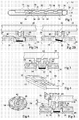
- FIG. 1 is a schematic section of a read / write system of smart cards.
- the device 10 comprises a housing 11 consisting of a lower housing portion 12 and a housing upper portion 14.
- a display screen 15 is attached to the housing upper portion 14.
- the device 10 comprises a printed circuit 16 on which are formed conductive tracks 18. Subsequently, the lower face of the upper housing portion 14, the face of the upper housing portion 14 on the side of the printed circuit 16.
- the metal tracks 18 are connected to components electronic, not shown. In addition, the means of reading and write data to a smart card are not shown.
- the device 10 comprises a flexible membrane 20, for example made of silicone or polyurethane, at the level of which are formed keys 22 of a keyboard, each key 22 corresponding to a portion of the membrane connected to the remainder of the membrane by a lip 24 device.
- Each key 22 comprises, on the side of the printed circuit 16, a conductive portion 26, for example a metal region. Under each key 22 are disposed vis-à-vis two ends each belonging to a metal track 18.
- each key 22 is remote from the median plane of the membrane 20 and is at a distance from the conductive tracks 18.
- the associated lip 24 allows a movement of the key 22 until the conductive portion 26 comes into contact with the ends of the underlying metal tracks 18, thereby establishing an electrical contact between the two metal tracks 18.
- the read / write system 10 includes an anti-intrusion device consisting of a dummy key 30 provided at the membrane 20 and which is not visible from outside the housing 11.
- the dummy key 30 is, so similar to the keys 22, connected to the rest of the membrane 20 by a peripheral lip 31 and comprises a conductive portion 32 on the side of its lower face.
- the ends of two metal tracks 34, 36 of the printed circuit 16 are arranged vis-à-vis under the fingertip 30.
- the two tracks 34, 36 form two portions of a safety line connected to a processing circuit, no represent.
- the processing circuit is adapted to determine whether the two metal tracks 34, 36 are electrically connected, for example by measuring the resistance across the safety line.
- Such an anti-intrusion device is described in the patent WO 02/33717 on behalf of Ascom Monetel and is, for example, provided on card readers to chips marketed by Sagem Monetel under the name EFT 930 and EFT 30.
- the dummy key 30 When the upper housing portion 14 is fixed to the lower housing portion 12, the dummy key 30 is permanently biased by the housing upper portion 14 so as to bear against the printed circuit board 16. In this case, the portion conductive 32 of the dummy key 30 comes into contact with the ends of the two tracks 34, 36. The electrical connection between the two metal tracks 34, 36 is detected by the processing circuit.
- the processing circuit is adapted to detect a change in the resistance of the safety line, indicating that an attempt to opening of the device 10 takes place.
- a disadvantage of such an anti-intrusion device is that it is not suitable for a hood upper portion consisting of several pieces.
- Another disadvantage of such an anti-intrusion device is that it does not detect an attempt to open the housing 11 which would consist of sliding the upper housing portion 14 relative to the lower housing portion 12 without spreading the two portions 12, 14 of each other in a direction perpendicular to the two housing portions 12, 14.
- Such a displacement of the upper housing portion 14 is called later lateral displacement.
- Such a sliding movement of the upper housing portion 14 does not cause movement of the dummy key 30 which is always held in abutment against the printed circuit 16. There is therefore no interruption of the electrical connection between the metal tracks 34, 36. A access to the content of the read / write system 10 is then possible without an intrusion attempt being detected.
- the present invention provides an anti-intrusion device for protecting objects contained in a housing consisting of first and second housing portions against an intrusion attempt consisting of a lateral displacement of the first housing portion relative to the second portion of the housing. housing.
- Another object of the invention is to provide an anti-intrusion device which has little modification of the structure of a conventional anti-intrusion device.
- the present invention provides an anti-intrusion device of a housing, the housing having a first housing portion attached to a second housing portion in a normal use position, the housing containing at least one movable member having a conductive region electrically connecting two conductive tracks in the normal use position, the first housing portion comprising a support member adapted to pivot the movable member when the first housing portion is moved laterally relative to the second housing portion; housing portion, which results in an interruption of the electrical connection between the two conductive tracks.
- the housing contains a membrane of a flexible material fixed relative to the housing, the movable element having a portion of the membrane connected to the remainder of the membrane by a deformable lip.
- the movable element comprises a recess and the support element comprises a pin projecting from the first housing portion and located at least partly in the recess.
- the support element comprises a flange projecting from the first housing portion and surrounding the movable element.
- the housing comprises a third housing portion attached to the second housing portion or the first housing portion and having at least one edge adjacent the first housing portion in the housing position. normal use.
- the third housing portion comprises an additional support member adapted to pivot the movable element when the third housing portion is moved laterally relative to the second housing portion, resulting in an interruption of the electrical connection between the two conductive tracks.
- the additional support element comprises an annular portion surrounding the movable element.
- the support element comprises a protrusion projecting from the first housing portion and extending at least partly between the movable member and the annular portion.
- the device comprises means adapted to move the movable element away from the conductive tracks when the first housing portion is moved away from the second housing portion.
- the additional support element extends at least partly between the first housing portion and the second housing portion, whereby the third housing portion causes movement. the first housing portion when the third housing portion is spaced from the second housing portion.
- the first housing portion comprises a bearing surface adapted to cooperate with the third housing portion from which it follows that the first housing portion drives in displacement the third housing portion when the first housing portion is spaced from the second housing portion.
- the present invention consists in providing, at the level of the upper housing portion bearing against the dummy key, an abutment element capable of coming into contact with a side wall of the dummy key during a lateral displacement of the upper portion. of housing.
- a lateral displacement of the upper housing portion causes a pivoting of the dummy key with respect to an axis perpendicular to the direction of movement of the upper housing portion and perpendicular to the axis of the dummy key so that the electrical connection between the two conductive tracks, to which the conductive portion of the dummy key is connected in the absence of displacement of the upper housing portion, is no longer assured. This gives a detection of an intrusion attempt by lateral displacement of the upper housing portion.
- FIG. 2A is a partial schematic section of a first embodiment of the anti-intrusion device according to the invention.
- the elements common to the read / write system 10 shown in FIG. 1 retain the same references. Only the elements useful for understanding the invention are shown.
- the dummy key 30 comprises a central recess 40 and the upper housing portion 14 comprises, on its underside side, a pin 42 which penetrates the central recess 40.
- the position of the upper housing portion 14 corresponds to normal use of the read / write system.
- FIG. 2B schematically represents the resulting position of the dummy key 30 during a lateral displacement of the upper housing portion 14.
- the material constituting the membrane 20, for example of silicone or polyurethane, and the dimensions of the dummy key 30 are chosen so that the dummy key 30 has a sufficient rigidity so that, when moving the upper housing portion 14, the dummy key 30 undergoes global pivoting rather than deformation.
- the dummy key 30 may correspond to a cylindrical portion whose outer diameter is of the order of 3 mm and the recess 40 may have a cylindrical shape whose diameter is of the order of 1.5 mm.
- FIG. 3 is a section similar to the section of FIG. 2 showing a second embodiment of the anti-intrusion device according to the invention in which, compared to the first embodiment, the upper housing portion 14 further comprises, on the side of its underside, a collar 44 which, when the upper housing portion 14 is in a normal position relative to the printed circuit 16, surrounds the dummy key 30. Therefore, during a lateral displacement of the portion upper housing 14 relative to the printed circuit 16, the pin 42 and the flange 44 exert a pressure on the dummy key 30 causing an overall pivoting thereof, which interrupts the electrical connection between the metal tracks 34, 36.
- the Second embodiment has the advantage of providing better control of the deformation of the dummy key 30 during a lateral displacement of the upper portion of the housing. 14. This avoids a situation in which the dummy key 30 deforms in such a way that the electrical connection between the metal tracks 34, 36 is not interrupted even in the event of lateral displacement of the upper housing portion 14.
- the first and second exemplary embodiments also have the advantage of allowing centering of the upper housing portion 14 with respect to the dummy key.
- a plurality of dummy keys 30 according to the first and second exemplary embodiments may be provided at the membrane 10.
- the pin 42 and the flange 44 it is possible to provide, in place of the pin 42 and the flange 44, a recess at the level of the upper housing portion 14 into which the dummy key 30 enters, the shape of the recess corresponding substantially to the shape of the dummy key 30.
- the bottom of the recess then bears against the dummy key 30 to hold against the printed circuit 16 so that an electrical connection between the metal tracks 34, 36 is ensured when the upper housing portion 14 is in a normal position of use relative to the lower housing portion 12.
- the side wall of the recess then acts as a stop element which, during a displacement side of the housing upper portion 14 relative to the lower housing portion 12, exerts a push against the dummy key 30 causing the pivoting thereof.
- the dummy key 30 provides both an anti-intrusion function when the casing upper portion 14 is moved away from the casing lower portion 12 and an anti-intrusion function when Lateral displacement of the housing upper portion 14 relative to the lower housing portion 12. It is clear that both anti-intrusion functions can be performed separately. In such a case, the dummy key of the anti-intrusion device during a lateral displacement of the upper housing portion 14 can remain stationary relative to the remainder of the membrane 20 when the upper housing portion 14 is moved away from the lower portion. 12 and change position only during a lateral displacement of the upper housing portion 14 relative to the lower housing portion 12. However, for to reduce the size of the anti-intrusion devices, it is advantageous to perform both anti-intrusion functions at the same dummy key.
- FIG. 4 is a perspective and schematic view of a read / write system 50 which, as for the read / write system shown in FIG. 1, comprises an upper housing portion 14, a lower housing portion 12, However, unlike the read / write system of FIG. 1, the system 50 comprises a plastron 52 fixed to the upper housing portion 14 and surrounding the screen. 15.
- the plastron 52 has an essentially aesthetic function since it may have a color different from the color of the upper housing portion 14, such a color being for example chosen by the purchaser of the read / write system.
- Figures 5 and 6 show a third embodiment of the anti-intrusion device according to the invention.
- Such a device makes it possible to detect both a lateral displacement of the upper housing portion 14 relative to the lower housing portion 12 and a lateral displacement of the plastron 52 relative to the lower housing portion 12.
- the dummy key 30 is disposed near the junction between the upper housing portion 14 and the plastron 52.
- the upper housing portion 14 comprises a protuberance 54 which extends from the underside of the upper portion of the housing. casing 14 adjacent to the dummy key 30 on the side of the plastron 52.
- the protuberance 54 forms a flange portion.
- the plastron 52 is extended by an extension 56 in the form of a ring which surrounds the dummy key 30 and the flange portion 54. The ring 56 thus extends partially between the upper housing portion 14 and the printed circuit board 16.
- the third exemplary embodiment thus allows the detection of an intrusion attempt which consists in moving laterally the upper portion of the casing 14 or the plastron 52.
- a lateral displacement of the upper casing portion 14 causes the pin 42 (and possibly the flange portion 54) to bear against the dummy key 30 which then bears against the ring 56.
- lateral displacement of the upper housing portion 14 thus causes a lateral displacement of the plastron 52, the overall movement of the plastron 52 and the upper housing portion 14 causing the pivoting of the dummy key 30 as described above in relation to the second exemplary embodiment.
- a lateral displacement of the plastron 52 causes the ring 56 to bear against the dummy key 30 which in turn presses against the pin 42.
- a lateral displacement of the plastron 52 therefore causes a lateral displacement of the portion upper housing 14, the overall movement of the plastron 52 and the upper housing portion 14 causing the pivoting of the dummy key 30 as described above in connection with the second embodiment.
- the upper housing portion 14 comprises a stair surface 58 adapted to cooperate with a surface 60 of complementary shape provided at the plastron 52.
- the flange portion 54 is located between the surface 60 of the plastron 52 and the printed circuit 16.
- the present invention is susceptible of various variations and modifications which will be apparent to those skilled in the art.
- the previously described embodiments relate to a smart card read / write system
- the present application can be applied to any type of system comprising a critical surface attached to a reference surface and for which it is desired detect a lateral displacement of the critical surface relative to the reference surface.
Abstract
Description
La présente invention concerne un dispositif anti-intrusion destiné à protéger des objets, par exemple des circuits électroniques, contenus dans un boîtier de façon à éviter que l'on ait accès auxdits objets ou à des informations contenues dans lesdits objets.The present invention relates to an anti-intrusion device for protecting objects, for example electronic circuits, contained in a housing so as to prevent access to said objects or to information contained in said objects.
Les systèmes de lecture et/ou d'écriture de données sur des cartes à puce ou des cartes magnétiques, par exemple les systèmes utilisés pour réaliser des opérations de paiement, comprennent généralement des dispositifs anti-intrusion.Systems for reading and / or writing data on smart cards or magnetic cards, for example the systems used to carry out payment transactions, generally include anti-intrusion devices.
La figure 1 est une coupe schématique d'un système de lecture/écriture de cartes à puce. Le dispositif 10 comprend un boîtier 11 constitué d'une portion inférieure de boîtier 12 et d'une portion supérieure de boîtier 14. Un écran d'affichage 15 est fixé à la portion supérieure de boîtier 14. Le dispositif 10 comprend un circuit imprimé 16 sur lequel sont réalisées des pistes conductrices 18. Par la suite, on appelle face inférieure de la portion supérieure de boîtier 14, la face de la portion supérieure de boîtier 14 du côté du circuit imprimé 16. Les pistes métalliques 18 sont reliées à des composants électroniques, non représentés. En outre, les moyens de lecture et d'écriture de données sur une carte à puce ne sont pas représentés. Le dispositif 10 comprend une membrane souple 20, par exemple en silicone ou en polyuréthane, au niveau de laquelle sont formées des touches 22 d'un clavier, chaque touche 22 correspondant à une portion de la membrane reliée au reste de la membrane par une lèvre 24 périphérique. Chaque touche 22 comprend, du côté du circuit imprimé 16, une portion conductrice 26 par exemple une région métallique. Sous chaque touche 22 sont disposées en vis-à-vis deux extrémités appartenant chacune à une piste métallique 18.Figure 1 is a schematic section of a read / write system of smart cards. The
En l'absence d'action extérieure sur le clavier, chaque touche 22 est éloignée du plan médian de la membrane 20 et se trouve à distance des pistes conductrices 18. Lorsqu'un utilisateur exerce une pression sur une touche 22, la lèvre 24 associée permet un déplacement de la touche 22 jusqu'à ce que la portion conductrice 26 entre en contact avec les extrémités des pistes métalliques 18 sous-jacentes, établissant alors un contact électrique entre les deux pistes métalliques 18.In the absence of external action on the keyboard, each
Le système de lecture/écriture 10 comprend un dispositif anti-intrusion constitué d'une touche factice 30 prévue au niveau de la membrane 20 et qui n'est pas visible depuis l'extérieur du boîtier 11. La touche factice 30 est, de façon analogue aux touches 22, reliée au reste de la membrane 20 par une lèvre périphérique 31 et comprend une portion conductrice 32 du côté de sa face inférieure. Les extrémités de deux pistes métalliques 34, 36 du circuit imprimé 16 sont disposées en vis-à-vis sous la touche factice 30. Les deux pistes 34, 36 forment deux portions d'une ligne de sécurité reliée à un circuit de traitement, non représenté. Le circuit de traitement est adapté à déterminer si les deux pistes métalliques 34, 36 sont connectées électriquement, par exemple en mesurant la résistance aux bornes de la ligne de sécurité. Un tel dispositif anti-intrusion est décrit dans le brevet
Lorsque la portion supérieure de boîtier 14 est fixée à la portion inférieure de boîtier 12, la touche factice 30 est sollicitée en permanence par la portion supérieure de boîtier 14 de façon à venir en appui contre le circuit imprimé 16. Dans ce cas, la portion conductrice 32 de la touche factice 30 vient en contact avec les extrémités des deux pistes 34, 36. La connexion électrique entre les deux pistes métalliques 34, 36 est détectée par le circuit de traitement.When the
Lorsqu'un individu tente d'accéder au contenu du boîtier 11 en retirant la portion supérieure de boîtier 14, la touche factice 30 n'est plus sollicitée par la portion supérieure de boîtier 14 et est ramenée par l'action de la lèvre 31 vers une position de repos à laquelle la portion conductrice 32 n'est plus en contact avec les pistes métalliques 34, 36. Le circuit de traitement est adapté à détecter une modification de la résistance de la ligne de sécurité, indiquant qu'une tentative d'ouverture du dispositif 10 a lieu.When an individual attempts to access the contents of the
Un inconvénient d'un tel dispositif anti-intrusion est qu'il n'est pas adapté à une portion supérieure de capot constituée de plusieurs morceaux.A disadvantage of such an anti-intrusion device is that it is not suitable for a hood upper portion consisting of several pieces.
Un autre inconvénient d'un tel dispositif anti-intrusion est qu'il ne permet pas de détecter une tentative d'ouverture du boîtier 11 qui consisterait à faire glisser la portion supérieure de boîtier 14 par rapport à la portion inférieure de boîtier 12 sans écarter les deux portions 12, 14 l'une de l'autre selon une direction perpendiculaire aux deux portions de boîtier 12, 14. Un tel déplacement de la portion supérieure de boîtier 14 est appelé par la suite déplacement latéral. En effet, un tel mouvement de glissement de la portion supérieure de boîtier 14 n'entraîne pas de déplacement de la touche factice 30 qui est toujours maintenue en appui contre le circuit imprimé 16. Il n'y a donc pas interruption de la connexion électrique entre les pistes métalliques 34, 36. Un accès au contenu du système de lecture/écriture 10 est alors possible sans qu'une tentative d'intrusion ne soit détectée.Another disadvantage of such an anti-intrusion device is that it does not detect an attempt to open the
La présente invention vise un dispositif anti-intrusion destiné à protéger des objets contenus dans un boîtier constitué de première et seconde portions de boîtier contre une tentative d'intrusion consistant en un déplacement latéral de la première portion de boîtier par rapport à la seconde portion de boîtier.The present invention provides an anti-intrusion device for protecting objects contained in a housing consisting of first and second housing portions against an intrusion attempt consisting of a lateral displacement of the first housing portion relative to the second portion of the housing. housing.
Un autre objet de l'invention est de prévoir un dispositif anti-intrusion qui modifie peu la structure d'un dispositif anti-intrusion classique.Another object of the invention is to provide an anti-intrusion device which has little modification of the structure of a conventional anti-intrusion device.
Pour atteindre ces objets, la présente invention prévoit un dispositif anti-intrusion d'un boîtier, le boîtier comportant une première portion de boîtier fixée à une deuxième portion de boîtier dans une position d'utilisation normale, le boîtier contenant au moins un élément mobile comportant une région conductrice reliant électriquement deux pistes conductrices dans la position d'utilisation normale, la première portion de boîtier comprenant un élément d'appui adapté à faire pivoter l'élément mobile lorsque la première portion de boîtier est déplacée latéralement par rapport à la deuxième portion de boîtier, d'où il résulte une interruption de la liaison électrique entre les deux pistes conductrices.To achieve these objects, the present invention provides an anti-intrusion device of a housing, the housing having a first housing portion attached to a second housing portion in a normal use position, the housing containing at least one movable member having a conductive region electrically connecting two conductive tracks in the normal use position, the first housing portion comprising a support member adapted to pivot the movable member when the first housing portion is moved laterally relative to the second housing portion; housing portion, which results in an interruption of the electrical connection between the two conductive tracks.
Selon un exemple de réalisation de l'invention, le boîtier contient une membrane d'un matériau souple fixe par rapport au boîtier, l'élément mobile comportant une portion de la membrane reliée au reste de la membrane par une lèvre déformable.According to an exemplary embodiment of the invention, the housing contains a membrane of a flexible material fixed relative to the housing, the movable element having a portion of the membrane connected to the remainder of the membrane by a deformable lip.
Selon un exemple de réalisation de l'invention, l'élément mobile comprend un évidement et l'élément d'appui comprend un pion se projetant à partir de la première portion de boîtier et situé au moins en partie dans l'évidement.According to an exemplary embodiment of the invention, the movable element comprises a recess and the support element comprises a pin projecting from the first housing portion and located at least partly in the recess.
Selon un exemple de réalisation de l'invention, l'élément d'appui comprend une collerette se projetant à partir de la première portion de boîtier et entourant l'élément mobile.According to an exemplary embodiment of the invention, the support element comprises a flange projecting from the first housing portion and surrounding the movable element.
Selon un exemple de réalisation de l'invention, le boîtier comprend une troisième portion de boîtier fixée à la deuxième portion de boîtier ou à la première portion de boîtier et ayant au moins un bord adjacent à la première portion de boîtier dans la position d'utilisation normale. La troisième portion de boîtier comprend un élément d'appui supplémentaire adapté à faire pivoter l'élément mobile lorsque la troisième portion de boîtier est déplacée latéralement par rapport à la deuxième portion de boîtier, d'où il résulte une interruption de la liaison électrique entre les deux pistes conductrices.According to an exemplary embodiment of the invention, the housing comprises a third housing portion attached to the second housing portion or the first housing portion and having at least one edge adjacent the first housing portion in the housing position. normal use. The third housing portion comprises an additional support member adapted to pivot the movable element when the third housing portion is moved laterally relative to the second housing portion, resulting in an interruption of the electrical connection between the two conductive tracks.
Selon un exemple de réalisation de l'invention, l'élément d'appui supplémentaire comprend une partie annulaire entourant l'élément mobile.According to an exemplary embodiment of the invention, the additional support element comprises an annular portion surrounding the movable element.
Selon un exemple de réalisation de l'invention, l'élément d'appui comprend une protubérance se projetant à partir de la première portion de boîtier et s'étendant au moins en partie entre l'élément mobile et la partie annulaire.According to an exemplary embodiment of the invention, the support element comprises a protrusion projecting from the first housing portion and extending at least partly between the movable member and the annular portion.
Selon un exemple de réalisation de l'invention, le dispositif comprend des moyens adaptés à éloigner l'élément mobile des pistes conductrices lorsque la première portion de boîtier est écartée de la deuxième portion de boîtier.According to an exemplary embodiment of the invention, the device comprises means adapted to move the movable element away from the conductive tracks when the first housing portion is moved away from the second housing portion.
Selon un exemple de réalisation de l'invention, l'élément d'appui supplémentaire s'étend au moins en partie entre la première portion de boîtier et la deuxième portion de boîtier d'où il résulte que la troisième portion de boîtier entraîne en déplacement la première portion de boîtier lorsque la troisième portion de boîtier est écartée de la deuxième portion de boîtier.According to an exemplary embodiment of the invention, the additional support element extends at least partly between the first housing portion and the second housing portion, whereby the third housing portion causes movement. the first housing portion when the third housing portion is spaced from the second housing portion.
Selon un exemple de réalisation de l'invention, la première portion de boîtier comprend une surface d'appui adaptée à coopérer avec la troisième portion de boîtier d'où il résulte que la première portion de boîtier entraîne en déplacement la troisième portion de boîtier lorsque la première portion de boîtier est écartée de la deuxième portion de boîtier.According to an exemplary embodiment of the invention, the first housing portion comprises a bearing surface adapted to cooperate with the third housing portion from which it follows that the first housing portion drives in displacement the third housing portion when the first housing portion is spaced from the second housing portion.
Ces objets, caractéristiques et avantages, ainsi que d'autres de la présente invention seront exposés en détail dans la description suivante d'exemples de réalisation particuliers faite à titre non-limitatif en relation avec les figures jointes parmi lesquelles :
- la figure 1, précédemment décrite, est une coupe schématique d'un système de lecture/écriture comportant un dispositif anti-intrusion classique ;
- les figures 2A et 2B représentent un premier exemple de réalisation d'un dispositif anti-intrusion selon l'invention, respectivement en l'absence de tentative d'intrusion et lors d'une tentative d'intrusion ;
- la figure 3 représente un deuxième exemple de réalisation du dispositif anti-intrusion selon l'invention ;
- la figure 4 représente schématiquement un exemple particulier de système de lecture/écriture ;
- la figure 5 représente un troisième exemple de réalisation du dispositif anti-intrusion selon l'invention adapté au système de lecture/écriture de la figure 4 ; et
- la figure 6 est une coupe du troisième exemple de réalisation du dispositif anti-intrusion de la figure 5 selon la ligne A-A.
- Figure 1, previously described, is a schematic section of a read / write system comprising a conventional anti-intrusion device;
- FIGS. 2A and 2B show a first embodiment of an anti-intrusion device according to the invention, respectively in the absence of attempted intrusion and during an intrusion attempt;
- FIG. 3 represents a second embodiment of the anti-intrusion device according to the invention;
- Figure 4 schematically shows a particular example of a read / write system;
- FIG. 5 represents a third embodiment of the anti-intrusion device according to the invention adapted to the read / write system of FIG. 4; and
- Figure 6 is a sectional view of the third embodiment of the anti-intrusion device of Figure 5 along the line AA.
Par souci de clarté, de mêmes éléments ont été désignés par de mêmes références aux différentes figures.For the sake of clarity, the same elements have been designated with the same references in the various figures.
La présente invention consiste à prévoir, au niveau de la portion supérieure de boîtier venant en appui contre la touche factice, un élément formant butée susceptible de venir en contact avec une paroi latérale de la touche factice lors d'un déplacement latéral de la portion supérieure de boîtier. De ce fait, un déplacement latéral de la portion supérieure de boîtier entraîne un pivotement de la touche factice par rapport à un axe perpendiculaire à la direction de déplacement de la portion supérieure de boîtier et perpendiculaire à l'axe de la touche factice de sorte que la connexion électrique entre les deux pistes conductrices, auxquelles la portion conductrice de la touche factice est reliée en l'absence de déplacement de la portion supérieure de boîtier, n'est plus assurée. On obtient ainsi une détection d'une tentative d'intrusion par déplacement latéral de la portion supérieure de boîtier.The present invention consists in providing, at the level of the upper housing portion bearing against the dummy key, an abutment element capable of coming into contact with a side wall of the dummy key during a lateral displacement of the upper portion. of housing. As a result, a lateral displacement of the upper housing portion causes a pivoting of the dummy key with respect to an axis perpendicular to the direction of movement of the upper housing portion and perpendicular to the axis of the dummy key so that the electrical connection between the two conductive tracks, to which the conductive portion of the dummy key is connected in the absence of displacement of the upper housing portion, is no longer assured. This gives a detection of an intrusion attempt by lateral displacement of the upper housing portion.
La figure 2A est une coupe partielle et schématique d'un premier exemple de réalisation du dispositif anti-intrusion selon l'invention. Les éléments communs au système de lecture/écriture 10 représenté en figure 1 conservent les mêmes références. Seuls les éléments utiles à la compréhension de l'invention sont représentés. Selon le premier exemple de réalisation, par rapport au système de lecture/écriture 10 représenté en figure 1, la touche factice 30 comprend un évidement central 40 et la portion supérieure de boîtier 14 comprend, du côté de sa face inférieure, un pion 42 qui pénètre dans l'évidement central 40. En figure 2A, la position de la portion supérieure de boîtier 14 correspond à une utilisation normale du système de lecture/écriture.FIG. 2A is a partial schematic section of a first embodiment of the anti-intrusion device according to the invention. The elements common to the read /
De façon analogue à ce qui a été décrit précédemment, lorsque la portion supérieure de boîtier 14 est éloignée du circuit imprimé 16, la touche factice 30 n'est plus maintenue en appui contre le circuit imprimé 16 de sorte que, sous l'action de la lèvre 31, la touche factice 30 s'éloigne du plan médian de la membrane 20, interrompant la connexion électrique entre les pistes métalliques 34, 36.In a similar manner to that described above, when the
En outre, lorsque la portion supérieure de boîtier 14 n'est pas éloignée du circuit imprimé 16 mais simplement déplacée latéralement par rapport à celui-ci, le pion 42 vient en butée contre la paroi interne de l'évidement 40 entraînant un pivotement global de la touche factice 30 ce qui vient interrompre la connexion électrique entre les pistes métalliques 34, 36.In addition, when the
La figure 2B représente schématiquement la position résultante de la touche factice 30 lors d'un déplacement latéral de la portion supérieure de boîtier 14. Le matériau constituant la membrane 20, par exemple en silicone ou en polyuréthane, et les dimensions de la touche factice 30 sont choisis de sorte que la touche factice 30 ait une rigidité suffisante afin que, lors du déplacement de la portion supérieure de boîtier 14, la touche factice 30 subit un pivotement global plutôt qu'une déformation. A cette fin, la touche factice 30 peut correspondre à une portion cylindrique dont le diamètre extérieur est de l'ordre de 3 mm et l'évidement 40 peut avoir une forme cylindrique dont le diamètre est de l'ordre de 1,5 mm.FIG. 2B schematically represents the resulting position of the dummy key 30 during a lateral displacement of the
La figure 3 est une coupe analogue à la coupe de la figure 2 représentant un deuxième exemple de réalisation du dispositif anti-intrusion selon l'invention dans lequel, par rapport au premier exemple de réalisation, la portion supérieure de boîtier 14 comprend en outre, du côté de sa face inférieure, une collerette 44 qui, lorsque la portion supérieure de boîtier 14 est à une position normale par rapport au circuit imprimé 16, entoure la touche factice 30. De ce fait, lors d'un déplacement latéral de la portion supérieure de boîtier 14 par rapport au circuit imprimé 16, le pion 42 et la collerette 44 exercent une poussée sur la touche factice 30 entraînant un pivotement global de celle-ci, ce qui interrompt la connexion électrique entre les pistes métalliques 34, 36. Le deuxième exemple de réalisation présente l'avantage d'assurer un meilleur contrôle de la déformation de la touche factice 30 lors d'un déplacement latéral de la portion supérieure de boîtier 14. On évite ainsi une situation selon laquelle la touche factice 30 se déformerait de façon telle que la connexion électrique entre les pistes métalliques 34, 36 ne serait pas interrompue même en cas de déplacement latéral de la portion supérieure de boîtier 14.FIG. 3 is a section similar to the section of FIG. 2 showing a second embodiment of the anti-intrusion device according to the invention in which, compared to the first embodiment, the
Les premier et deuxième exemples de réalisation présentent en outre l'avantage de permettre un centrage de la portion supérieure de boîtier 14 par rapport à la touche factice 30 lors de la fixation de la portion supérieure de boîtier 14 à la portion inférieure de boîtier 12. Plusieurs touches factices 30 selon les premier et deuxième exemples de réalisation peuvent être prévues au niveau de la membrane 10.The first and second exemplary embodiments also have the advantage of allowing centering of the
Selon une variante des premier et deuxième exemples de réalisation, on peut prévoir, à la place du pion 42 et de la collerette 44, un évidement au niveau de la portion supérieure de boîtier 14 dans lequel pénètre la touche factice 30, la forme de l'évidement correspondant sensiblement à la forme de la touche factice 30. Le fond de l'évidement vient alors en appui contre la touche factice 30 pour la maintenir contre le circuit imprimé 16 de sorte qu'une connexion électrique entre les pistes métalliques 34, 36 est assurée lorsque la portion supérieure de boîtier 14 est dans une position normale d'utilisation par rapport à la portion inférieure de boîtier 12. La paroi latérale de l'évidement joue alors le rôle d'élément de butée qui, lors d'un déplacement latéral de la portion supérieure de boîtier 14 par rapport à la portion inférieure de boîtier 12, exerce une poussée contre la touche factice 30 entraînant le pivotement de cette dernière.According to a variant of the first and second exemplary embodiments, it is possible to provide, in place of the
Dans les exemples de réalisation qui précèdent, la touche factice 30 assure à la fois une fonction anti-intrusion lors d'un écartement de la portion supérieure de boîtier 14 par rapport à la portion inférieure de boîtier 12 et une fonction anti-intrusion lors d'un déplacement latéral de la portion supérieure de boîtier 14 par rapport à la portion inférieure de boîtier 12. Il est clair que les deux fonctions anti-intrusion peuvent être réalisées de façon séparée. Dans un tel cas, la touche factice du dispositif anti-intrusion lors d'un déplacement latéral de la portion supérieure de boîtier 14 peut rester immobile par rapport au reste de la membrane 20 lorsque la portion supérieure de boîtier 14 est éloignée de la portion inférieure de boîtier 12 et ne changer de position que lors d'un déplacement latéral de la portion supérieure de boîtier 14 par rapport à la portion inférieure de boîtier 12. Toutefois, pour réduire l'encombrement des dispositifs anti-intrusion, il est avantageux de réaliser les deux fonctions anti-intrusion au niveau d'une même touche factice.In the preceding embodiments, the
La figure 4 est une vue en perspective et schématique d'un système de lecture/écriture 50 qui, comme pour le système de lecture/écriture représenté en figure 1, comprend une portion supérieure de boîtier 14, une portion inférieure de boîtier 12, des touches 22 d'un clavier et un écran d'affichage 15. Toutefois, à la différence du système de lecture/écriture de la figure 1, le système 50 comprend un plastron 52 fixé à la portion supérieure de boîtier 14 et entourant l'écran 15. Le plastron 52 a une fonction essentiellement esthétique puisqu'il peut avoir une couleur différente de la couleur de la portion supérieure de boîtier 14, une telle couleur étant par exemple choisie par l'acquéreur du système de lecture/écriture.FIG. 4 is a perspective and schematic view of a read /
Les figures 5 et 6 représentent un troisième exemple de réalisation du dispositif anti-intrusion selon l'invention. Un tel dispositif permet de détecter à la fois un déplacement latéral de la portion supérieure de boîtier 14 par rapport à la portion inférieure de boîtier 12 et un déplacement latéral du plastron 52 par rapport à la portion inférieure de boîtier 12. Selon le troisième exemple de réalisation, la touche factice 30 est disposée à proximité de la jonction entre la portion supérieure de boîtier 14 et le plastron 52. La portion supérieure de boîtier 14 comprend une protubérance 54 qui s'étend à partir de la face inférieure de la portion supérieure de boîtier 14 de façon adjacente à la touche factice 30 du côté du plastron 52. La protubérance 54 forme une portion de collerette. Le plastron 52 se prolonge par une extension 56 en forme d'anneau qui entoure la touche factice 30 et la portion de collerette 54. L'anneau 56 s'étend donc partiellement entre la portion supérieure de boîtier 14 et le circuit imprimé 16.Figures 5 and 6 show a third embodiment of the anti-intrusion device according to the invention. Such a device makes it possible to detect both a lateral displacement of the
Le troisième exemple de réalisation permet donc la détection d'une tentative d'intrusion qui consiste à déplacer latéralement la portion supérieure de boîtier 14 ou le plastron 52. En effet, un déplacement latéral de la portion supérieure de boîtier 14 entraîne la mise en appui du pion 42 (et éventuellement de la portion de collerette 54) contre la touche factice 30 qui vient alors en appui contre l'anneau 56. Un déplacement latéral de la portion supérieure de boîtier 14 entraîne donc un déplacement latéral du plastron 52, le mouvement global du plastron 52 et de la portion supérieure de boîtier 14 entraînant le pivotement de la touche factice 30 comme cela a été décrit précédemment en relation au deuxième exemple de réalisation. De façon analogue, un déplacement latéral du plastron 52 entraîne la mise en appui de l'anneau 56 contre la touche factice 30 qui vient à son tour appuyer contre le pion 42. Un déplacement latéral du plastron 52 entraîne donc un déplacement latéral de la portion supérieure de boîtier 14, le mouvement global du plastron 52 et de la portion supérieure de boîtier 14 entraînant le pivotement de la touche factice 30 comme cela a été décrit précédemment en relation au deuxième exemple de réalisation.The third exemplary embodiment thus allows the detection of an intrusion attempt which consists in moving laterally the upper portion of the
La portion supérieure de boîtier 14 comprend une surface en escaliers 58 adaptée à coopérer avec une surface 60 de forme complémentaire prévue au niveau du plastron 52. La portion de collerette 54 est située entre la surface 60 du plastron 52 et le circuit imprimé 16. Avec un tel agencement, lorsque le plastron 52 est écarté de la portion inférieure de boîtier 12, l'anneau 56 vient en appui contre la face inférieure de la portion supérieure de boîtier 14, entraînant le déplacement de la portion supérieure de boîtier 14. De même, lorsque la portion supérieure de boîtier 14 est écartée de la portion inférieure de boîtier 12, la surface 58 vient en appui contre la surface 60 entraînant le déplacement du plastron 52. La touche factice 30 selon le troisième exemple de réalisation sert donc également de dispositif anti-intrusion lors d'un écartement de la portion supérieure de boîtier 14 ou du plastron 52 par rapport à la portion inférieure de boîtier 12.The
Bien entendu, la présente invention est susceptible de diverses variantes et modifications qui apparaîtront à l'homme de l'art. En particulier, bien que les exemples de réalisation précédemment décrits concernent un système de lecture/écriture de cartes à puce, la présente application peut s'appliquer à tout type de système comprenant une surface critique fixée à une surface de référence et pour lequel on souhaite détecter un déplacement latéral de la surface critique par rapport à la surface de référence.Of course, the present invention is susceptible of various variations and modifications which will be apparent to those skilled in the art. In particular, although the previously described embodiments relate to a smart card read / write system, the present application can be applied to any type of system comprising a critical surface attached to a reference surface and for which it is desired detect a lateral displacement of the critical surface relative to the reference surface.
Claims (10)
Applications Claiming Priority (1)
| Application Number | Priority Date | Filing Date | Title |
|---|---|---|---|
| FR0650617A FR2897702B1 (en) | 2006-02-22 | 2006-02-22 | ANTI-INTRUSION DEVICE |
Publications (2)
| Publication Number | Publication Date |
|---|---|
| EP1826702A1 true EP1826702A1 (en) | 2007-08-29 |
| EP1826702B1 EP1826702B1 (en) | 2008-10-08 |
Family
ID=37005970
Family Applications (1)
| Application Number | Title | Priority Date | Filing Date |
|---|---|---|---|
| EP07102585A Active EP1826702B1 (en) | 2006-02-22 | 2007-02-16 | Anti-intrusion device |
Country Status (4)
| Country | Link |
|---|---|
| EP (1) | EP1826702B1 (en) |
| AT (1) | ATE410743T1 (en) |
| DE (1) | DE602007000155D1 (en) |
| FR (1) | FR2897702B1 (en) |
Cited By (3)
| Publication number | Priority date | Publication date | Assignee | Title |
|---|---|---|---|---|
| DE102008003264A1 (en) * | 2008-01-04 | 2009-07-09 | Demmel Ag | Keypad for e.g. access control keyboard of bank terminal, has safety contact partner producing constant contact with printed circuit board independent from opening-or closing condition of switch contact partner |
| GB2468720A (en) * | 2009-03-20 | 2010-09-22 | Keymat Technology Ltd | Mechanism for detecting the separation of a component from a part |
| WO2016203022A1 (en) * | 2015-06-19 | 2016-12-22 | Ingenico Group | System for protecting an input device |
Citations (3)
| Publication number | Priority date | Publication date | Assignee | Title |
|---|---|---|---|---|
| FR2815733A1 (en) * | 2000-10-20 | 2002-04-26 | Ascom Monetel Sa | Banks/portable telephone/computer security key board having special button pressed function state activating electronic key intrusion detection and when intrusion detected releasing key |
| US20030047433A1 (en) * | 2000-03-17 | 2003-03-13 | Pascal Moree | Anti-spoofing elastomer membrane for secure electronic modules |
| FR2860643A1 (en) * | 2003-10-07 | 2005-04-08 | Thales Sa | ANTI-INTRUSION DEVICE, IN PARTICULAR FOR AN ELECTRONIC PAYMENT TERMINAL |
-
2006
- 2006-02-22 FR FR0650617A patent/FR2897702B1/en not_active Expired - Fee Related
-
2007
- 2007-02-16 DE DE602007000155T patent/DE602007000155D1/en active Active
- 2007-02-16 AT AT07102585T patent/ATE410743T1/en not_active IP Right Cessation
- 2007-02-16 EP EP07102585A patent/EP1826702B1/en active Active
Patent Citations (3)
| Publication number | Priority date | Publication date | Assignee | Title |
|---|---|---|---|---|
| US20030047433A1 (en) * | 2000-03-17 | 2003-03-13 | Pascal Moree | Anti-spoofing elastomer membrane for secure electronic modules |
| FR2815733A1 (en) * | 2000-10-20 | 2002-04-26 | Ascom Monetel Sa | Banks/portable telephone/computer security key board having special button pressed function state activating electronic key intrusion detection and when intrusion detected releasing key |
| FR2860643A1 (en) * | 2003-10-07 | 2005-04-08 | Thales Sa | ANTI-INTRUSION DEVICE, IN PARTICULAR FOR AN ELECTRONIC PAYMENT TERMINAL |
Cited By (8)
| Publication number | Priority date | Publication date | Assignee | Title |
|---|---|---|---|---|
| DE102008003264A1 (en) * | 2008-01-04 | 2009-07-09 | Demmel Ag | Keypad for e.g. access control keyboard of bank terminal, has safety contact partner producing constant contact with printed circuit board independent from opening-or closing condition of switch contact partner |
| DE102008003264B4 (en) * | 2008-01-04 | 2016-07-28 | Demmel Ag | Tamper-proof keyboard with protection against removal of the key caps |
| GB2468720A (en) * | 2009-03-20 | 2010-09-22 | Keymat Technology Ltd | Mechanism for detecting the separation of a component from a part |
| GB2468720B (en) * | 2009-03-20 | 2011-09-07 | Keymat Technology Ltd | A Component carrying a mechanism for detecting separation of the component from a part |
| US8294590B2 (en) | 2009-03-20 | 2012-10-23 | Keymat Technology Limited | Mechanism for detecting separation of a component from a part and a component carrying such a mechanism |
| WO2016203022A1 (en) * | 2015-06-19 | 2016-12-22 | Ingenico Group | System for protecting an input device |
| FR3037688A1 (en) * | 2015-06-19 | 2016-12-23 | Ingenico Group | SYSTEM FOR SECURING A SEIZURE DEVICE |
| US10922443B2 (en) | 2015-06-19 | 2021-02-16 | Ingenico Group | System for protecting an input device |
Also Published As
| Publication number | Publication date |
|---|---|
| DE602007000155D1 (en) | 2008-11-20 |
| ATE410743T1 (en) | 2008-10-15 |
| EP1826702B1 (en) | 2008-10-08 |
| FR2897702B1 (en) | 2008-04-25 |
| FR2897702A1 (en) | 2007-08-24 |
Similar Documents
| Publication | Publication Date | Title |
|---|---|---|
| EP2194491B1 (en) | Electronic card with control means | |
| EP2269155B1 (en) | Protection device for an electronic system | |
| EP0961986B1 (en) | Card, in particular chip card, reading device | |
| EP2146562B1 (en) | Device for protecting an electronic component | |
| FR2911970A1 (en) | ELECTRICAL CONTROL DEVICE | |
| WO2002010865A1 (en) | Device for data input into a portable object | |
| FR2834579A3 (en) | Optical position sensing is built into mouse or computer to control screen cursor | |
| FR2667713A1 (en) | MICRO-CIRCUIT BOARD READER, REDUCED. | |
| EP1826702B1 (en) | Anti-intrusion device | |
| FR2717000A1 (en) | Peripheral device with keyboard and screen for computer. | |
| EP1671341B1 (en) | Anti-intrusion device primarily for an electronic payment terminal | |
| FR2771834A1 (en) | ELECTRICAL CONNECTION DEVICE FOR COOPERATING WITH A MOBILE ELECTRONIC MEDIUM | |
| EP0231409A1 (en) | Card reader | |
| WO2008107279A1 (en) | Touch surface sensor | |
| EP1424710B1 (en) | Control device for at least two functions of an element and/or at least two different parts of an element | |
| EP0653719B1 (en) | Electronic switch in particular for the detection of the presence of an IC card in a card reader | |
| WO2017013606A1 (en) | Compact card reader | |
| FR2908552A1 (en) | Electronic system e.g. chip card read/write system, has conductive portion remote from conductors when external action is not exerted on deformable region, and key to deform region for permitting portion to contact with conductors | |
| EP1444645A1 (en) | Computer light pen and computer to be used with same | |
| EP0711439B1 (en) | Switch for detecting the presence of an electronic memory card in a read/write device | |
| EP2101280A1 (en) | Payment terminal with a magnetic reader having a lateral slit | |
| FR3085514A1 (en) | MEMORY CARD READING TERMINAL INCLUDING TILT COMPENSATION MEANS | |
| FR2665000A1 (en) | Data consultation apparatus | |
| CA2998625A1 (en) | Secure keyboard for data entry electronic device | |
| WO2021234297A1 (en) | Learning device and learning kit |
Legal Events
| Date | Code | Title | Description |
|---|---|---|---|
| PUAI | Public reference made under article 153(3) epc to a published international application that has entered the european phase |
Free format text: ORIGINAL CODE: 0009012 |
|
| AK | Designated contracting states |
Kind code of ref document: A1 Designated state(s): AT BE BG CH CY CZ DE DK EE ES FI FR GB GR HU IE IS IT LI LT LU LV MC NL PL PT RO SE SI SK TR |
|
| AX | Request for extension of the european patent |
Extension state: AL BA HR MK YU |
|
| 17P | Request for examination filed |
Effective date: 20080228 |
|
| GRAP | Despatch of communication of intention to grant a patent |
Free format text: ORIGINAL CODE: EPIDOSNIGR1 |
|
| AKX | Designation fees paid |
Designated state(s): AT BE BG CH CY CZ DE DK EE ES FI FR GB GR HU IE IS IT LI LT LU LV MC NL PL PT RO SE SI SK TR |
|
| GRAS | Grant fee paid |
Free format text: ORIGINAL CODE: EPIDOSNIGR3 |
|
| GRAA | (expected) grant |
Free format text: ORIGINAL CODE: 0009210 |
|
| AK | Designated contracting states |
Kind code of ref document: B1 Designated state(s): AT BE BG CH CY CZ DE DK EE ES FI FR GB GR HU IE IS IT LI LT LU LV MC NL PL PT RO SE SI SK TR |
|
| REG | Reference to a national code |
Ref country code: GB Ref legal event code: FG4D Free format text: NOT ENGLISH |
|
| REG | Reference to a national code |
Ref country code: CH Ref legal event code: EP |
|
| REG | Reference to a national code |
Ref country code: IE Ref legal event code: FG4D Free format text: LANGUAGE OF EP DOCUMENT: FRENCH |
|
| REF | Corresponds to: |
Ref document number: 602007000155 Country of ref document: DE Date of ref document: 20081120 Kind code of ref document: P |
|
| PG25 | Lapsed in a contracting state [announced via postgrant information from national office to epo] |
Ref country code: SI Free format text: LAPSE BECAUSE OF FAILURE TO SUBMIT A TRANSLATION OF THE DESCRIPTION OR TO PAY THE FEE WITHIN THE PRESCRIBED TIME-LIMIT Effective date: 20081008 |
|
| NLV1 | Nl: lapsed or annulled due to failure to fulfill the requirements of art. 29p and 29m of the patents act | ||
| PG25 | Lapsed in a contracting state [announced via postgrant information from national office to epo] |
Ref country code: AT Free format text: LAPSE BECAUSE OF FAILURE TO SUBMIT A TRANSLATION OF THE DESCRIPTION OR TO PAY THE FEE WITHIN THE PRESCRIBED TIME-LIMIT Effective date: 20081008 Ref country code: LT Free format text: LAPSE BECAUSE OF FAILURE TO SUBMIT A TRANSLATION OF THE DESCRIPTION OR TO PAY THE FEE WITHIN THE PRESCRIBED TIME-LIMIT Effective date: 20081008 Ref country code: ES Free format text: LAPSE BECAUSE OF FAILURE TO SUBMIT A TRANSLATION OF THE DESCRIPTION OR TO PAY THE FEE WITHIN THE PRESCRIBED TIME-LIMIT Effective date: 20090119 Ref country code: BG Free format text: LAPSE BECAUSE OF FAILURE TO SUBMIT A TRANSLATION OF THE DESCRIPTION OR TO PAY THE FEE WITHIN THE PRESCRIBED TIME-LIMIT Effective date: 20090108 |
|
| PG25 | Lapsed in a contracting state [announced via postgrant information from national office to epo] |
Ref country code: PL Free format text: LAPSE BECAUSE OF FAILURE TO SUBMIT A TRANSLATION OF THE DESCRIPTION OR TO PAY THE FEE WITHIN THE PRESCRIBED TIME-LIMIT Effective date: 20081008 Ref country code: LV Free format text: LAPSE BECAUSE OF FAILURE TO SUBMIT A TRANSLATION OF THE DESCRIPTION OR TO PAY THE FEE WITHIN THE PRESCRIBED TIME-LIMIT Effective date: 20081008 Ref country code: NL Free format text: LAPSE BECAUSE OF FAILURE TO SUBMIT A TRANSLATION OF THE DESCRIPTION OR TO PAY THE FEE WITHIN THE PRESCRIBED TIME-LIMIT Effective date: 20081008 Ref country code: IS Free format text: LAPSE BECAUSE OF FAILURE TO SUBMIT A TRANSLATION OF THE DESCRIPTION OR TO PAY THE FEE WITHIN THE PRESCRIBED TIME-LIMIT Effective date: 20090208 Ref country code: PT Free format text: LAPSE BECAUSE OF FAILURE TO SUBMIT A TRANSLATION OF THE DESCRIPTION OR TO PAY THE FEE WITHIN THE PRESCRIBED TIME-LIMIT Effective date: 20090218 Ref country code: FI Free format text: LAPSE BECAUSE OF FAILURE TO SUBMIT A TRANSLATION OF THE DESCRIPTION OR TO PAY THE FEE WITHIN THE PRESCRIBED TIME-LIMIT Effective date: 20081008 |
|
| REG | Reference to a national code |
Ref country code: IE Ref legal event code: FD4D |
|
| PG25 | Lapsed in a contracting state [announced via postgrant information from national office to epo] |
Ref country code: RO Free format text: LAPSE BECAUSE OF FAILURE TO SUBMIT A TRANSLATION OF THE DESCRIPTION OR TO PAY THE FEE WITHIN THE PRESCRIBED TIME-LIMIT Effective date: 20081008 Ref country code: EE Free format text: LAPSE BECAUSE OF FAILURE TO SUBMIT A TRANSLATION OF THE DESCRIPTION OR TO PAY THE FEE WITHIN THE PRESCRIBED TIME-LIMIT Effective date: 20081008 Ref country code: DK Free format text: LAPSE BECAUSE OF FAILURE TO SUBMIT A TRANSLATION OF THE DESCRIPTION OR TO PAY THE FEE WITHIN THE PRESCRIBED TIME-LIMIT Effective date: 20081008 Ref country code: IE Free format text: LAPSE BECAUSE OF FAILURE TO SUBMIT A TRANSLATION OF THE DESCRIPTION OR TO PAY THE FEE WITHIN THE PRESCRIBED TIME-LIMIT Effective date: 20081008 |
|
| PLBE | No opposition filed within time limit |
Free format text: ORIGINAL CODE: 0009261 |
|
| STAA | Information on the status of an ep patent application or granted ep patent |
Free format text: STATUS: NO OPPOSITION FILED WITHIN TIME LIMIT |
|
| BERE | Be: lapsed |
Owner name: SAGEM MONETEL Effective date: 20090228 |
|
| PG25 | Lapsed in a contracting state [announced via postgrant information from national office to epo] |
Ref country code: IT Free format text: LAPSE BECAUSE OF FAILURE TO SUBMIT A TRANSLATION OF THE DESCRIPTION OR TO PAY THE FEE WITHIN THE PRESCRIBED TIME-LIMIT Effective date: 20081008 Ref country code: CZ Free format text: LAPSE BECAUSE OF FAILURE TO SUBMIT A TRANSLATION OF THE DESCRIPTION OR TO PAY THE FEE WITHIN THE PRESCRIBED TIME-LIMIT Effective date: 20081008 Ref country code: SE Free format text: LAPSE BECAUSE OF FAILURE TO SUBMIT A TRANSLATION OF THE DESCRIPTION OR TO PAY THE FEE WITHIN THE PRESCRIBED TIME-LIMIT Effective date: 20090108 |
|
| 26N | No opposition filed |
Effective date: 20090709 |
|
| PG25 | Lapsed in a contracting state [announced via postgrant information from national office to epo] |
Ref country code: MC Free format text: LAPSE BECAUSE OF NON-PAYMENT OF DUE FEES Effective date: 20090228 Ref country code: SK Free format text: LAPSE BECAUSE OF FAILURE TO SUBMIT A TRANSLATION OF THE DESCRIPTION OR TO PAY THE FEE WITHIN THE PRESCRIBED TIME-LIMIT Effective date: 20081008 |
|
| REG | Reference to a national code |
Ref country code: FR Ref legal event code: CA Ref country code: FR Ref legal event code: CD |
|
| PG25 | Lapsed in a contracting state [announced via postgrant information from national office to epo] |
Ref country code: BE Free format text: LAPSE BECAUSE OF NON-PAYMENT OF DUE FEES Effective date: 20090228 |
|
| PG25 | Lapsed in a contracting state [announced via postgrant information from national office to epo] |
Ref country code: GR Free format text: LAPSE BECAUSE OF FAILURE TO SUBMIT A TRANSLATION OF THE DESCRIPTION OR TO PAY THE FEE WITHIN THE PRESCRIBED TIME-LIMIT Effective date: 20090109 |
|
| PG25 | Lapsed in a contracting state [announced via postgrant information from national office to epo] |
Ref country code: LU Free format text: LAPSE BECAUSE OF NON-PAYMENT OF DUE FEES Effective date: 20090216 |
|
| PG25 | Lapsed in a contracting state [announced via postgrant information from national office to epo] |
Ref country code: HU Free format text: LAPSE BECAUSE OF FAILURE TO SUBMIT A TRANSLATION OF THE DESCRIPTION OR TO PAY THE FEE WITHIN THE PRESCRIBED TIME-LIMIT Effective date: 20090409 |
|
| PG25 | Lapsed in a contracting state [announced via postgrant information from national office to epo] |
Ref country code: TR Free format text: LAPSE BECAUSE OF FAILURE TO SUBMIT A TRANSLATION OF THE DESCRIPTION OR TO PAY THE FEE WITHIN THE PRESCRIBED TIME-LIMIT Effective date: 20081008 |
|
| PG25 | Lapsed in a contracting state [announced via postgrant information from national office to epo] |
Ref country code: CY Free format text: LAPSE BECAUSE OF FAILURE TO SUBMIT A TRANSLATION OF THE DESCRIPTION OR TO PAY THE FEE WITHIN THE PRESCRIBED TIME-LIMIT Effective date: 20081008 |
|
| REG | Reference to a national code |
Ref country code: CH Ref legal event code: PL |
|
| PG25 | Lapsed in a contracting state [announced via postgrant information from national office to epo] |
Ref country code: LI Free format text: LAPSE BECAUSE OF NON-PAYMENT OF DUE FEES Effective date: 20110228 Ref country code: CH Free format text: LAPSE BECAUSE OF NON-PAYMENT OF DUE FEES Effective date: 20110228 |
|
| REG | Reference to a national code |
Ref country code: FR Ref legal event code: PLFP Year of fee payment: 9 |
|
| REG | Reference to a national code |
Ref country code: FR Ref legal event code: TP Owner name: COMPAGNIE INDUSTRIELLE ET FINANCIERE D'INGENIE, FR Effective date: 20160111 |
|
| REG | Reference to a national code |
Ref country code: FR Ref legal event code: PLFP Year of fee payment: 10 |
|
| REG | Reference to a national code |
Ref country code: FR Ref legal event code: CA Effective date: 20160304 Ref country code: FR Ref legal event code: CD Owner name: INGENICO GROUP, FR Effective date: 20160304 |
|
| REG | Reference to a national code |
Ref country code: FR Ref legal event code: PLFP Year of fee payment: 11 |
|
| REG | Reference to a national code |
Ref country code: FR Ref legal event code: PLFP Year of fee payment: 12 |
|
| REG | Reference to a national code |
Ref country code: GB Ref legal event code: 732E Free format text: REGISTERED BETWEEN 20220407 AND 20220413 |
|
| REG | Reference to a national code |
Ref country code: DE Ref legal event code: R081 Ref document number: 602007000155 Country of ref document: DE Owner name: BANKS AND ACQUIRES INTERNATIONAL HOLDING, FR Free format text: FORMER OWNER: INGENICO FRANCE, NEUILLY SUR SEINE, FR |
|
| PGFP | Annual fee paid to national office [announced via postgrant information from national office to epo] |
Ref country code: FR Payment date: 20230227 Year of fee payment: 17 |
|
| PGFP | Annual fee paid to national office [announced via postgrant information from national office to epo] |
Ref country code: GB Payment date: 20230220 Year of fee payment: 17 Ref country code: DE Payment date: 20230216 Year of fee payment: 17 |