EP1826643B1 - Robot system - Google Patents
Robot system Download PDFInfo
- Publication number
- EP1826643B1 EP1826643B1 EP05814619.2A EP05814619A EP1826643B1 EP 1826643 B1 EP1826643 B1 EP 1826643B1 EP 05814619 A EP05814619 A EP 05814619A EP 1826643 B1 EP1826643 B1 EP 1826643B1
- Authority
- EP
- European Patent Office
- Prior art keywords
- robot
- laser
- locus
- laser beam
- tool
- Prior art date
- Legal status (The legal status is an assumption and is not a legal conclusion. Google has not performed a legal analysis and makes no representation as to the accuracy of the status listed.)
- Active
Links
- 230000005855 radiation Effects 0.000 claims description 30
- 238000000034 method Methods 0.000 claims description 9
- 238000003860 storage Methods 0.000 claims description 9
- 238000003466 welding Methods 0.000 description 172
- 238000010586 diagram Methods 0.000 description 36
- 230000033001 locomotion Effects 0.000 description 15
- 230000014509 gene expression Effects 0.000 description 10
- 230000008859 change Effects 0.000 description 5
- 230000007246 mechanism Effects 0.000 description 5
- 230000007423 decrease Effects 0.000 description 4
- 239000000835 fiber Substances 0.000 description 4
- 230000008569 process Effects 0.000 description 4
- 230000000694 effects Effects 0.000 description 3
- 230000008901 benefit Effects 0.000 description 2
- 238000005516 engineering process Methods 0.000 description 2
- 230000006870 function Effects 0.000 description 2
- 230000003287 optical effect Effects 0.000 description 2
- 230000005540 biological transmission Effects 0.000 description 1
- 230000003247 decreasing effect Effects 0.000 description 1
- 238000003698 laser cutting Methods 0.000 description 1
- 230000002093 peripheral effect Effects 0.000 description 1
- 238000005392 polarisation enhancment during attached nucleus testing Methods 0.000 description 1
Images


Classifications
-
- B—PERFORMING OPERATIONS; TRANSPORTING
- B25—HAND TOOLS; PORTABLE POWER-DRIVEN TOOLS; MANIPULATORS
- B25J—MANIPULATORS; CHAMBERS PROVIDED WITH MANIPULATION DEVICES
- B25J9/00—Programme-controlled manipulators
- B25J9/16—Programme controls
- B25J9/1656—Programme controls characterised by programming, planning systems for manipulators
- B25J9/1664—Programme controls characterised by programming, planning systems for manipulators characterised by motion, path, trajectory planning
-
- B—PERFORMING OPERATIONS; TRANSPORTING
- B23—MACHINE TOOLS; METAL-WORKING NOT OTHERWISE PROVIDED FOR
- B23K—SOLDERING OR UNSOLDERING; WELDING; CLADDING OR PLATING BY SOLDERING OR WELDING; CUTTING BY APPLYING HEAT LOCALLY, e.g. FLAME CUTTING; WORKING BY LASER BEAM
- B23K26/00—Working by laser beam, e.g. welding, cutting or boring
- B23K26/08—Devices involving relative movement between laser beam and workpiece
- B23K26/0869—Devices involving movement of the laser head in at least one axial direction
- B23K26/0876—Devices involving movement of the laser head in at least one axial direction in at least two axial directions
- B23K26/0884—Devices involving movement of the laser head in at least one axial direction in at least two axial directions in at least in three axial directions, e.g. manipulators, robots
-
- G—PHYSICS
- G05—CONTROLLING; REGULATING
- G05B—CONTROL OR REGULATING SYSTEMS IN GENERAL; FUNCTIONAL ELEMENTS OF SUCH SYSTEMS; MONITORING OR TESTING ARRANGEMENTS FOR SUCH SYSTEMS OR ELEMENTS
- G05B2219/00—Program-control systems
- G05B2219/30—Nc systems
- G05B2219/39—Robotics, robotics to robotics hand
- G05B2219/39177—Compensation position working point as function of inclination tool, hand
-
- G—PHYSICS
- G05—CONTROLLING; REGULATING
- G05B—CONTROL OR REGULATING SYSTEMS IN GENERAL; FUNCTIONAL ELEMENTS OF SUCH SYSTEMS; MONITORING OR TESTING ARRANGEMENTS FOR SUCH SYSTEMS OR ELEMENTS
- G05B2219/00—Program-control systems
- G05B2219/30—Nc systems
- G05B2219/39—Robotics, robotics to robotics hand
- G05B2219/39401—Machine tool coordinates to manipulator coordinates
-
- G—PHYSICS
- G05—CONTROLLING; REGULATING
- G05B—CONTROL OR REGULATING SYSTEMS IN GENERAL; FUNCTIONAL ELEMENTS OF SUCH SYSTEMS; MONITORING OR TESTING ARRANGEMENTS FOR SUCH SYSTEMS OR ELEMENTS
- G05B2219/00—Program-control systems
- G05B2219/30—Nc systems
- G05B2219/39—Robotics, robotics to robotics hand
- G05B2219/39572—Task, tool manipulation
-
- G—PHYSICS
- G05—CONTROLLING; REGULATING
- G05B—CONTROL OR REGULATING SYSTEMS IN GENERAL; FUNCTIONAL ELEMENTS OF SUCH SYSTEMS; MONITORING OR TESTING ARRANGEMENTS FOR SUCH SYSTEMS OR ELEMENTS
- G05B2219/00—Program-control systems
- G05B2219/30—Nc systems
- G05B2219/40—Robotics, robotics mapping to robotics vision
- G05B2219/40416—Planning for variable length tool, laser beam as tool
-
- G—PHYSICS
- G05—CONTROLLING; REGULATING
- G05B—CONTROL OR REGULATING SYSTEMS IN GENERAL; FUNCTIONAL ELEMENTS OF SUCH SYSTEMS; MONITORING OR TESTING ARRANGEMENTS FOR SUCH SYSTEMS OR ELEMENTS
- G05B2219/00—Program-control systems
- G05B2219/30—Nc systems
- G05B2219/45—Nc applications
- G05B2219/45138—Laser welding
-
- G—PHYSICS
- G05—CONTROLLING; REGULATING
- G05B—CONTROL OR REGULATING SYSTEMS IN GENERAL; FUNCTIONAL ELEMENTS OF SUCH SYSTEMS; MONITORING OR TESTING ARRANGEMENTS FOR SUCH SYSTEMS OR ELEMENTS
- G05B2219/00—Program-control systems
- G05B2219/30—Nc systems
- G05B2219/45—Nc applications
- G05B2219/45165—Laser machining
Definitions
- the present invention relates to a robot system to which a tool having a driving shaft is fitted, and more particularly, to a robot system which performs a laser processing.
- EP 1 228 835 A1 discloses a remote laser welding system comprising a laser generator and an optical head having a mirror orienting unit and a focusing device, to orient and focus the laser beam, wherein said optical head can be translated vertically.
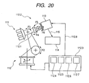
- Fig. 20 shows a 6 axis (Fl to F6) industrial robot arm in which a laser processing tool is fitted on the end portion of the robot arm.
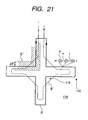
- Fig. 21 is a diagram showing a continuous processing geometry which is overlapped with a manipulator geometry movement.
- a tool 113 is a laser processing tool, and a workpiece 114 is processed by a laser beam 115.
- a known device 111 includes a control unit 112.3, and its control signal is transmitted to a tool 113 and/or a robot 112 through a transmission medium 112.8 such as a fieldbus.
- a processor means 112.7 and a determination means 112.6 of a memory unit 112.4 and a determination unit 112.5 are fitted to the control unit 112.3.
- Fig. 21 schematically shows a cross-shaped movement path B of a front end of a tool (TCP) for performing a laser carving on a surface of a workpiece 114.
- a movement geometry B' of an end 112.2 of the robot 112 (shown in Fig. 20 ) or a robot arm 112.1 to which the tool 113 is fixed is overlapped with a processing geometry B.
- the movement geometry B' of the robot is obviously different from that of a processing geometry B in a corner 116 of the processing geometry, that is, a region where a considerable change occurs in a route of the processing geometry B.
- the movement geometry B' of the robot stays in a space region B" ("MOBILITY TUBE" which is marked with a slant line in Fig. 21 ), which encloses the movement geometry B' in every side, and thus a deviation ⁇ B from the processing geometry B corresponds to a maximum moving amplitude of the 3-degree-of-freedom tool 113.
- the speed should be decreased in the region 116 where a sudden direction change of the processing geometry B occurs.
- the processing time of the workpiece 114 is greatly increased, a bad effect that a robot shaft is not active is compensated by allowing the movement geometry B' to progress or delay probably departing from the preset processing geometry B in the predetermined region 116 as the result of a real-time movement control in which the manipulator 112 and the tool 113 are mixed by the device.
- the processing geometry B in the region 116 is securely traced by a specific motion of the tool 113 which processes at much faster uniform speed.
- the processing process is not influenced by the bad effect caused by the inactivity of the manipulator 112 by allowing the tool 113 to trace the processing geometry B while the manipulator 112 decreases the length of the geometry movement B' in a region where a processing profile is difficult.
- Patent Document 1 there are not provided a detailed description and a figure with respect to a configuration of the robot arm and a control of the robot arm and the laser scanner.
- the device can not be achieved at all by specifying simple functions.
- the invention solves the above-mentioned problems. It is an object of the invention to provide a robot system which moves along an instructed geometry and controls the driving shaft of the tool so as to move a laser beam to a processing geometry desired by the manipulator. Such an object is achieved by a robot system according to claim 1.
- a robot system including:
- the tool includes a lens which is disposed in a traveling path of the laser beam and which moves forwardly and backwardly in a traveling direction of the laser beam by the driving shafts of the tool, and the robot control device controls a focal position of the laser beam by driving the driving shafts of the tool to operate the lens.
- the tool includes a mirror which is disposed in the traveling path of the laser beam and which rotates by the driving shafts of the tool, and the robot control device controls the focal position of the laser beam by driving the driving shafts of the tool to rotate the mirror.
- a control point of the robot is the center of a driving shaft of the mirror
- the robot control device includes:
- robot control device includes:
- the robot control device includes a start command for starting the radiation of the laser beam and an end command for ending the radiation, and the start command sets an interpolation method and a moving speed of the focal position of the laser beam in a radiation area.
- the tool shaft calculator includes:
- the tool shaft calculator generates a locus of the focal position of the laser beam including a combination of two circular arcs and one line on the basis of two instructed focal position of the laser beam and a radius and an angle of a circular arc using the specified focal positions of the laser beam as end points.
- the tool shaft calculator generates the locus including the combination of two circular arcs and one line on the basis of a radius and an angle of a first circular arc using one of the two instructed focal positions of the laser beam as an end point and a radius and an angle of a second circular arc using the other instructed focal position of the laser beam as an end point.
- the tool shaft calculator generates an auxiliary point apart from a start point of the locus by a specified distance in the front of the start point and adds an auxiliary locus, which connects the auxiliary point to the start point, to the locus.
- the tool shaft calculator generates an auxiliary point apart from an end point of the locus by a specified distance in the back of the end point and adds an auxiliary locus, which connects the auxiliary point to the end point, to the locus.
- control a robot and a point of an end portion of a tool are moved on a manipulator's purpose, whereby an interference with a surrounding can be certainly avoided, thereby particularly obtaining an advantage that a system using a robot can be securely built.
- Fig. 1 is a configuration diagram illustrating a robot system according to an embodiment of the invention.
- a robot 1 has six joints. Each of them has a mechanism which is driven by servo motors, and a laser head 3 is fitted to a front end portion thereof.
- a robot control device 2 is connected to the robot 1, a laser welding device 5, and the laser head 3, respectively.
- a manipulator has a pendant 4 so as to perform a instruction or a manipulation of the robot 1 and the laser head 3.
- the laser head 3 is connected to the laser welding device 5 through a fiber 6.
- a laser oscillator is built in the laser welding device 5.
- a laser beam outputted from the laser oscillator is incident on the laser head 3 through the fiber 6.
- the laser head 3 includes a mirror 7 (see Fig. 2 ), and the incident laser beam is reflected on the mirror 7, whereby its direction is changed to be radiated to an object, thereby performing a welding.
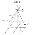
- Fig. 2 is a diagram briefly illustrating the laser head 3 as shown in Fig. 1 .
- the laser beam which is incident on the laser head 3 through the fiber 6 passes a lens in the laser head 3, and then it is concentrated. After the condensing, its direction is changed to the object by the mirror 7, and a focus is connected to a focal position W.
- the mirror 7 includes a rotation drive mechanism which is operated by servo motors (not shown) turning around axis X and servo motors (not shown) turning around axis Y in a coordinate system as shown in Fig. 2 .
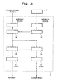
- Fig. 3 is a block diagram illustrating the robot control device 2 as shown in Fig. 1 .
- Fig. 3 only shows certain parts related to the invention from the configuration of the robot control device 2, and the other parts are omitted.
- the robot control device 2 includes robot servo amplifiers 21 which control the servo motors of the above-mentioned robot 1 (shown in Fig. 1 ), laser head servo amplifiers 22 which control the servo motors of the laser head 3 (shown in Fig. 1 ), a manipulator file storage 23, a command analyzer 24, a robot locus calculator 25, and a laser locus calculator 26.
- the manipulator file storage 23 stores operation programs of the robot 1 and the laser head 3 which are created by a manipulator and parameters related to the laser welding as a file format.
- the manipulator can write the operation programs and configure the parameters through the pendant 4.
- the command analyzer 24 reads out the operation programs and the parameters for the laser welding which are stored in the manipulator file storage 23 so as to analyze the command. Depending on the analyzed command, a robot operation command and a laser head operation command are transmitted to the robot locus calculator 25, the laser locus calculator 26, and the laser welding device 5, respectively.
- the robot locus calculator 25 transmits an instruction to the robot servo amplifiers 21 by calculating the locus on the basis of the command so as to operate the robot 1.
- the laser locus calculator 26 transmits an instruction to the laser head servo amplifiers 22 by calculating the locus on the basis of the command so as to operate the mirror 7 (shown in Fig. 2 ).
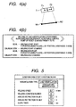
- Fig. 4(a) illustrates an example when the line interpolation welding is performed from a welding start point W1 to a welding end point W2 by driving the mirror 7 (shown in Fig. 2 ) while the laser head 3 (shown in Fig. 1 ) is moved from P1 to P2 by the robot 1 (shown in Fig. 1 ).
- Fig. 4 (b) is the operation program corresponding to the operation shown in Fig. 4(a) .
- "MOVL" in the first line is a command that a control point of the robot 1 is moved to P1 in a straight line and the mirror 7 in the laser head 3 is operated.
- the control point is previously configured to be the rotation center of the mirror 7.
- W1 becomes a laser-beam focal position.
- CRLASON CSF#1 in the next line is a welding start command.
- the laser welding is started by controlling the laser head 3 and the laser welding device 5 (shown in Fig. 1 ) in accordance with a configuration of a laser-welding start condition file marked with CSF#1.
- the laser-welding start condition file will be fully described as below (see Fig. 5 ).'
- MOVL in the third line is a command that the mirror 7 in the laser head 3 is operated while the control point of the robot 1 is moved to P2 in a straight line.
- the line connecting W1 to W2 denotes a locus of a laser-beam focal position.
- CEF#1 in the fourth line is a welding end command.
- the laser welding is finished by controlling the laser head 3 and the laser welding device 5 in accordance with a configuration of a laser-welding end condition file marked with CEF#1.
- the laser-welding end condition file will be described later (see Fig. 6 ).
- the manipulator should move the robot 1 and the laser head 3 to the desired position in advance through the pendant 4 (shown in Fig. 1 ), instruct the positions of the driving shafts of the robot 1 and the mirror 7 in the laser head 3 so as to prepare the operation program like that shown in Fig. 4 (b) , and record them in the manipulator file storage 23.
- the command analyzer 24 executes the command described in the operation program by reading out them line by line, and controls the laser welding device 5 by transmitting a position instruction to the robot locus calculator 25 and the laser locus calculator 26 on the basis of the condition which is specified by the laser-welding start condition file and the laser-welding end condition file.
- the robot locus calculator 25 calculates an interpolation with respect to the locus of when the mirror 7 in the laser head 3 is moved from P1 to P2. The calculation is performed by means of the known technology, and the position instruction value is calculated at every predetermined control cycle.
- the laser locus calculator 26 calculates the rotation angle of the mirror 7 from the welding speed which is instructed in accordance with the control point position of the robot 1 at every control cycle, the welding line position, and the laser-welding condition start file.
- the robot locus calculator 25 and the laser locus calculator 26 transmit the position instruction obtained by the calculation to the servo amplifiers 21 and 22. when the laser welding is finished, the laser output is turned off in accordance with the configuration of the laser-welding end condition file.
- the robot control device 2 controls the movement speed of the robot so as to allow the laser-beam focal position to be the welding start point W1 in the control point P1 of the robot, and the laser-beam focal position to be the welding end point W2 in the control point P2 of the robot.
- Fig. 5 is a diagram showing an example of the laser-welding start condition file in the robot control device as shown in Fig. 3 .
- Fig. 6 is a diagram showing an example of the laser-welding end condition file in the robot control device as shown in Fig. 3 .
- the manipulator can display these laser-welding condition files on the display by manipulating the pendant 4. Additionally, the manipulator can change freely the configuration of the laser-welding condition file by manipulating the pendant 4 so as to record the configuration in the manipulator file storage 23.
- the laser-welding condition file exists plurally, and can be identified by the unique number of every file.
- the manipulator can perform various configurations with respect to each of the laser-welding condition files. In an example as shown in Fig. 4 , the first laser-welding condition file is marked with CSF#1, and the first laser-welding end condition file is marked with CEF#1.
- the CRLASON command (shown in Fig. 4(b) ) denotes the welding start command
- the laser-welding start condition file as shown in Fig. 5 is specified by an operand.
- the CRLASOF command (shown in Fig. 4 (b) ) denotes the welding end command.
- the laser-welding end condition file as shown in Fig. 6 is specified by the operand.
- the laser locus calculator 26 calculates the welding point in the section between the CRLASON command and the CRLASOF command in accordance with the interpolation method specified in "interpolation type" item of the laser-welding start condition file as shown in Fig. 5 .
- the above-mentioned Fig. 4 is an example of when the line interpolation is specified in "interpolation type" item.
- the welding condition number (12 in case of Fig. 5 ) described in the specified laser-welding start condition file is transmitted to the laser welding device 5.
- the welding condition output watt and the like
- the laser welding device 5 outputs the laser beam in accordance with the welding condition.
- Fig. 7 is a diagram showing an example of the instruction value transmitted to the laser welding device at the time of starting the laser welding due to the laser-welding start condition file as shown in Fig. 5 .
- voltage of 3.0 V specified as the initial "analog instruction value 1" is outputted to the laser welding device 5, and voltage of 3.0 V specified as the analog instruction value 1 increases up to voltage of 7.0 V specified as "analog instruction value 2" for 0.06 seconds specified by "slope timer".
- Fig. 8 is a diagram showing an example of the instruction value transmitted to the laser welding device at the time of ending the laser welding due to the laser-welding end condition file as shown in Fig. 6 .
- the voltage of 7.0 V specified as the initial "analog instruction value 1" outputted to the laser welding device 5 decreases down to the voltage of 4.0 V specified as “analog instruction value 2" for the time of 0.05 seconds specified as "slope timer".
- Fig. 4 is an example of the line interpolation
- the interpolation method based on the welding line can be specified by "interpolation type" item of the laser-welding start condition file.
- Fig. 9 is an example that a circular arc interpolation is selected in "interpolation type”.
- Fig. 9 (a) shows the figure that a circular arc interpolation welding is performed from the welding start point W3 to the welding end point W5 via W4 while the laser head 3 is moved in a straight line to P3, P4, and P5 by the robot 1.
- Fig. 9(b) shows the operation program corresponding to the operation.
- "MOVL" in the first line is a command that the mirror 7 in the laser head 3 is operated while the control point of the robot 1 is moved in a straight line to P3.
- the control point is previously configured to be the rotation center of the mirror 7.
- W3 becomes the laser-beam focal position.
- CRLASON CSF#2 in the next line is the welding start command.
- the laser welding is started by controlling the laser head 3 and the laser welding device 5 (shown in Fig. 1 ) in accordance with a configuration of the laser-welding start condition file marked with CSF#2
- "MOVL" in the third line is the command that the mirror 7 in the laser head 3 is operated so as to allow the welding locus (the locus of the laser-beam focal position) to be the circular arc interpolation while the control point of the robot 1 is moved in a straight line to P4.
- "MOVL" in the fourth line is the command that the mirror 7 in the laser head 3 is operated so as to allow the welding locus (locus of the laser-beam focal position) to be the circular arc interpolation while the control point of the robot 1 is moved in a straight line to P5.
- the circular arc connecting W3, W4, and W5 becomes the locus of the laser-beam focal position.
- CEF#2 in the fifth line is the welding end command.
- the laser welding is finished by controlling the laser head 3 and the laser welding device 5 in accordance with a configuration of a laser-welding end condition file marked with CEF#2.
- Fig. 10 (a) shows the figure of when the line interpolation welding is performed from the welding start point W6 to the welding end point W7 by rotating the mirror 7 in the state that the rotation center of the mirror 7 in the laser head 3 is stopped at P6.
- Fig. 10 (b) shows the operation program corresponding to the operation.
- "MOVL" in the first line is a command that the mirror 7 in the laser head 3 is operated while the control point of the robot 1 is moved in a straight line to P6.
- the control point is previously configured to be the rotation center of the mirror 7.
- point W6 becomes the laser-beam focal position.
- CRLASON CSF#1 in the next line is the welding start command.
- the laser welding is started by controlling the laser head 3 and the laser welding device 5 (shown in Fig. 1 ) in accordance with the configuration of the laser-welding start condition file (shown in Fig. 5 ) marked with CSF#1.
- MOVL in the third line is a command that the mirror 7 in the laser head 3 is operated while the control point of the robot 1 is moved to P6 (i.e. there is no movement).
- the line connecting the points W6 to W7 becomes the locus of the laser-beam focal position.
- CEF#1 in the fourth line is the welding end command.
- the laser welding is finished by controlling the laser head 3 and the laser welding device 5 in accordance with the configuration of the laser-welding end condition file (shown in Fig. 6 ) marked with CEF#1.
- the interpolation control with respect to the focal position W is not performed outside the welding area. That is, it is controlled so as to regularly output angle data from the present instructed position to the next instructedposition of the servo motors in the laser head 3.
- Fig. 11 is a diagram showing an example of a correlation between a welding instructed position and the position of the laser head 3.
- the robot 1 shown in Fig. 1
- the mirror 7 shown in Fig. 1
- the robot 1 is manipulated so as to allow the laser beam LB1 to face the welding start point W1.
- the robot 1 is manipulated so as to move the laser head 3 to P2
- the mirror 7 in the laser head 3 is manipulated so as to allow the laser beam LB2 to face the welding end point W2.
- the coordinate system that the control point (P1 and P2 in case of Fig. 11 ) of the robot 1 is the starting point is configured, and it is configured that the coordinate system at the time of starting the welding is marked with ⁇ L1 ⁇ and the coordinate system at the time of ending the welding is marked with ⁇ L2 ⁇ .
- a robot coordinate system is marked with ⁇ R ⁇ and a base portion of the robot 1 is configured to.be the starting point.
- the robot locus calculator 25 and the laser locus calculator 26 it is described about the robot locus calculator 25 and the laser locus calculator 26 in the case that the welding start point W1 and the welding end point W2 as shown in Fig. 11 are instructed
- Fig. 12 is a diagram fully illustrating the robot locus calculator 25 and the laser locus calculator 26 of the robot control device 2 as shown in Fig. 3 .
- the laser locus calculator 26 includes a position calculating section 31, a calculating section of times of control cycle 32, and a laser position instruction generating section 33.
- the position calculating section 31 outputs the position RW1 of the welding start point W1 as viewed in the robot coordinate system ⁇ R ⁇ by using the following expression on the basis of a position and posture RL1T of the laser-head coordinate system ⁇ L1 ⁇ at the time of starting the welding as viewed in the robot coordinate system ⁇ R ⁇ and a position L1W1 of the welding start point W1 as viewed in the laser-head coordinate system ⁇ L1 ⁇ at the time of starting the welding.
- RW ⁇ 1 RL ⁇ 1 ⁇ T ⁇ L ⁇ 1 ⁇ W ⁇ 1
- the position calculating section 31 outputs the position RW2 with respect to the welding end point W2 as viewed in the robot coordinate system ⁇ R ⁇ by using the following expression on the basis of a position and posture RL2T of the laser-head coordinate system ⁇ L2 ⁇ at the time of ending the welding as viewed in the robot coordinate system ⁇ R ⁇ and a position L2W2 of the welding end point W2 as viewed in the laser-head coordinate system ⁇ L2 ⁇ at the time of ending the welding.
- RW ⁇ 2 RL ⁇ 2 ⁇ T ⁇ L ⁇ 2 ⁇ W ⁇ 2
- the calculating section of times of control cycle 32 calculates the vector D from the welding start point W1 to the welding end point W2 on the basis of the position RW1 of the welding start point W1 as viewed in the robot coordinate system ⁇ R ⁇ and the position RW2 of the welding end point W2 as viewed in the robot coordinate system ⁇ R ⁇ which are calculated through the expressions (1) and (2).
- the welding speed V instructed by the laser-welding start condition file as shown in Fig. 5 is acquired from the command analyzer 24, and then the times N of the control cycle ⁇ t from the welding start point W1 to the welding end point W2 is calculated by using the following expression.
- ⁇ t is an actual number larger than 0 and N is a positive number larger than O or more.
- N D / V ⁇ ⁇ t
- the laser position instruction generating section 33 calculates the position RWk of the welding point Wk as viewed in the robot coordinate system ⁇ R ⁇ by inputting the position RWk of the welding start point W1 as viewed in the robot coordinate system ⁇ R ⁇ , the vector D from the welding start point W1 to the welding end point W2, the times of control cycle N calculated by the expression (3), and the control cycle at k-th (k is a positive number, but, 0 ⁇ k ⁇ N) time to the following expression.
- RWk RW ⁇ 1 + D ⁇ k / N
- the laser position instruction generating section 33 outputs the position LkWk of the welding point Wk as viewed in the laser-head coordinate system ⁇ Lk ⁇ in the control cycle at kth time by using the following expression on the basis of a position and posture RLkT (described later) of the laser-head coordinate system ⁇ Lk ⁇ as viewed in the robot coordinate system ⁇ R ⁇ in the control cycle at kth time calculated by the robot locus calculator 25 and the position RWk of the welding point Wk as viewed in the robot coordinate system ⁇ R ⁇ in the control cycle at kth time calculated by using the expression (4).
- LkWk LkRT ⁇ RWk
- the robot locus calculator 25 outputs a position and posture RLkT of the laser-head coordinate system ⁇ Lk ⁇ as viewed in the robot coordinate system ⁇ R ⁇ in the control cycle at kth time by using the following expression on the basis of a position and posture RL1T of the laser-head coordinate system ⁇ L1 ⁇ at the time of starting the welding as viewed in the robot coordinate system ⁇ R ⁇ , a position and posture RL2T of the laser-head coordinate system ⁇ L2 ⁇ at the time of ending the welding as viewed in the robot coordinate system ⁇ R ⁇ , and the times of control cycle N acquired by using the expression (3) in the calculating section of times of control cycle 32.
- RLkT RL ⁇ 1 ⁇ T + RL ⁇ 2 ⁇ T - RL ⁇ 1 ⁇ T ⁇ k / N
- the output RLkT of the robot locus calculator 25 and the output LkWk of the laser position instruction generating section 33 are inputted to the robot servo amplifiers 21 and the laser head servo amplifiers 22, respectively.
- the robot servo amplifiers 21 and the laser head servo amplifiers 22 operate the servo motors of the robot 1 and the servo motors of the laser head 3, respectively.
- the position and a posture RLkt of the laser-head coordinate system ⁇ Lk ⁇ as viewed in the robot coordinate system ⁇ R ⁇ in the control cycle at kth time is acquired by using the times of control cycle N acquired by the calculating section of times of control cycle 32 in the laser locus calculator 26. That is, the servo motors in the robot 1 and the servo motors in the laser head 3 use the same times of control cycle N, whereby the servo motors in the robot 1 and the servo motors in the laser head 3 are started and stopped at the same time, thereby having the same moving time in the welding area between the servo motors in the robot 1 and the servo motors in the laser head 3. Namely, the locus from the welding start point W1 to the welding end point W2 at the time of a playback is performed as the instruction. Additionally, the positions of the laser head 3 at the welding start point N1 and the welding end point W2 are performed as the instruction.
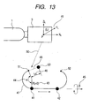
- Fig. 13 is a diagram showing the locus of the laser-beam focal position by means of a combination of a circular arc and a line generated by the laser locus calculator 26.
- the first focal position 41 and the second focal position 42 are points which are actually instructed by the manipulator manipulating the robot 1 and the laser head 3 so as to move laser beam 50. It is configured that the welding is performed in the direction from the first focal position 41 to the second focal position 42.
- a circular arc radius 43 and a circular arc angle 44 are connected to the line connecting the first focal position 41 and the second focal position 42, and thus a circular arc radius (R shown in Fig. 13 ) and an angle ( ⁇ shown in Fig. 13 ) make one locus.
- the laser-beam focal locus 47 is a locus which connects a first circular arc using the first focal position 41 as an end point, a second circular arc using a second focal position 42 as an end point, the focal position 41, and the focal position 42, that is, a section which connects the other end point (the welding start point 51) of the first circular arc as shown in Fig. 13 , the first focal position 41, the second focal position 42, and the other end point (the welding end point 52) of the second circular arc.
- a surface angle 45 is angle that determines a plane having the laser-beam focal locus 47, is defined as an angle around the line connecting the first focal position 41 and the second focal position 42 ( ⁇ shown in Fig. 13 ), and exists on a plane having the laser-beam focal locus 47.
- a vector which is perpendicular to a vector facing from the first focal position 41 to the second focal position 42 is perpendicular to axis ZL of the laser-head coordinate system 49, it is configured that the surface angle 45 is 0°.
- a front distance 46 is defined as a distance (L0 shown in Fig. 13 ) between the welding start point 51 and the auxiliary point 53 extending from the welding start point 51 to the outside of a tangent line of the circular arc.
- An auxiliary locus 48 is defined as the range from the auxiliary point 53 to the welding start point 51. Since the auxiliary locus 48 is not the welding area but a section provided for the laser-beam focal locus so as to pass the welding start point 51 as described below, the laser beam 50 is not radiated in this section.
- the robot 1 and the mirror 7 of the laser head 3 move at high speed relative to the section of the laser-beam focal locus 47 in order to decrease a tact time in a section other than the laser-beam focal locus 47.
- the focal locus does not pass the welding start point 51 due to causes such as a tracing delay of the servo system.
- the auxiliary point 53 is provided, and the laser-beam focal locus is allowed to pass the auxiliary point 53 and the welding start point 51 even when the laser-beam focal position moves at high speed in the section other than the laser-beam focal locus 47.
- the laser locus calculator 26 (shown in Fig. 12 ) generates the laser-beam focal locus 47.
- the information which is necessary for generating the laser-beam focal locus 47 can be inputted in the configuration screen shown in Fig. 14.
- Fig. 14 is a diagram showing an example that a configuration with respect to the laser locus calculator 26 is performed.
- the configuration item shown here is displayed on the screen by the manipulator manipulating the pendant 4.
- the manipulator can record the result of a configuration or a change in the manipulator file storage 23.
- laser-welding start condition file and "laser-welding end condition file” are already described with reference to Figs. 5 and 6 .
- the laser-welding condition file is marked with a number in the same way as described above. In an example as shown in Fig. 14 , all of them are specified as the first file.
- “Circular arc radius”, “circular arc angle”, “predicted distance”, and “surface angle” correspond to the circular arc radius R, the circular arc angle ⁇ , the front distance LO, and the surface angle ⁇ as shown in Fig. 13 , respectively.
- predicted locus speed the moving speed of the laser-beam focal position is specified in the section of the auxiliary locus 48. However, as described above, the laser beam 50 is not radiated in the section of the auxiliary locus 48.
- the first focal position 41 as shown in Fig. 13 is registered in “robot position (start)” and “laser head focal position (start)".
- the second focal position 42 as shown in Fig. 13 is registered in “robot position (end) " and "laser head focal position (end)”.
- the laser locus calculator 26 can generate the laser-beam focal locus including the combination of the circular arc and the line on the basis of two instruction points and the parameters with respect to several shapes. Therefore, it is remarkably simple to generate the locus relative to a method which needs plural instruction points. Additionally, it is possible to generate plural laser-beam focal locuses having different shapes and sizes by changing the parameter relative to a shape.
- the auxiliary point 53 is provided so as to allow the laser-beam focal locus to pass the welding start point 51.
- the auxiliary point 53 is not provided and the generated locus may be defined as the range of the welding start point 51 to the welding end point 52.
- the surface angle 45 ( ⁇ shown in Fig. 13 ) determining the slope of the plane having the laser-beam focal locus 47 is provided.
- the configuration of the surface angle ⁇ may be omitted.
- the circular arc in the side of the first focal position 41 and the circular arc in the side of the second focal position 42 are the same circular arc having the same size and shape using the same circular arc radius R and the same circular arc angle ⁇ , but it is possible to make circular arcs having different sizes and shapes on both sides of the first focal position 41 and the second focal position 42 by using different circular arcs and angles.
- Fig. 15 is a diagram showing an example of the laser-beam focal locus including the combination of the circular arc and the line generated by the laser locus calculator 26 (shown in Fig. 12 ) when a negative value is inputted in "circular arc" item of the configuration screen as shown in Fig. 14 .
- the circular arcs shown in Fig. 15 have a reverse direction relative to those shown in Fig. 13 .
- the circular arc radius can not have a negative value, but in the embodiment the direction of the circular arc is determined by means of the positive and negative of the circular arc radius 43. It is possible to intuitively configure the direction of the circular arc without adding another configuration item to the configuration screen shown in Fig. 14 .
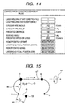
- Fig. 16 is a flowchart illustrating the case that a shape of the laser-beam focal locus 47 is determined by the specified circular arc radius R and the specified circular arc angle ⁇ in the configuration screen as shown in Fig. 14 in the laser locus calculator 26 (shown in Fig. 12 ).
- step S01 shown in Fig. 16 whether the circular arc radius R is 0 or not is determined.
- one line locus calculation (described below, see Fig. 17 ) is performed in step S02, and when it is not, the present step is moved to step S03 so as to determine whether the circular arc angle ⁇ is 0 or not.
- the present step is moved to a U-shaped locus calculation (described below, see Fig. 18 ) in S04, and when it is not, the present step is moved to step 505 so as to determine whether the circular arc ⁇ is 360° or more.
- step S06 When the circular arc angle ⁇ is 360° or more, the present step is moved to step S06 so as to perform one circle locus calculation (described below, see Fig. 19 ). When it is not, the present step is moved to step S07 so as to perform the locus calculation (described above, see Figs. 13 to 15 ) including the combination of the circular arc and the line.
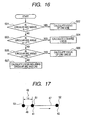
- Fig. 17 is a diagram showing one line locus (step S02) generated by the laser locus calculator 26 (shown in Fig. 12 ).
- the circular arc radius R is 0 in Fig. 13 , it is not possible to make a circular arc using the first focal position 41 or the second focal position 42 as the end point. Intuitively, it is an image that the center of the circular arc is absorbed by the first focal position 41 and the second focal position 42. Accordingly, when the circular arc R is 0, one line locus as shown in Fig. 17 is made. In this case, the preset circular arc angle ⁇ or the preset surface angle ⁇ is disregarded. Additionally, the welding start point 51 and the welding end point 52 become the same points as the first focal position 41 and the second focal position 42.
- Fig. 18 is a diagram showing a U-shaped locus (step S04) including three lines perpendicular to each other which are generated by the laser locus calculator 26 (shown in Fig. 12 ).
- the circular arc angle ⁇ is 0 in Fig. 13 , it is not possible to make a circular arc using the first focal position 41 or the second focal position 42 as the end point. Intuitively, it is an image that the center of the circular arc exists but the portion of the circular arc disappeared. Therefore, when the circular arc angle ⁇ is 0, three line locuses perpendicular to each other are made as shown in Fig. 18 .
- the direction of the line using the first focal position 41 and the second focal position 42 as the end points can be changed by specifying the positive and negative of the circular arc radius R.
- (a) is when the circular arc radius R is positive and (b) is when the circular arc radius R is negative.
- Fig. 19 is a diagram showing one circle locus (step S06) generated by the laser locus calculator 26 (shown in Fig. 12 ).
- the circular arc angle ⁇ is 360° or more in Fig. 13
- a circle that the circular arc using the first focal position 41 as the end point is closed is made. Therefore, when the circular arc angle ⁇ is 360° or more, one circle locus is made as shown in Fig. 19 .
- the portion of the circular arc angle ⁇ which is larger than 360° overlaps the locus of the circle.
- the laser-beam focal locus 47 is not drawn between the first focal position 41 and the second focal position 42, the second focal position 42 is necessary as an instruction point so as to determine the plane having the laser-beam focal locus 47.
- the direction of the circle is changed depending on the positive and negative of the circular arc radius R. In Fig. 19, (a) is when the circular arc radius R is positive, and (b) is when the circular arc R is negative.
- the laser head 3 having two driving shafts as shown in Fig. 2 which turns the mirror 7 around axis X and axis Y.
- the mechanism with a shaft which operates the lens shown in Fig. 2 along the traveling direction of the laser beam and add a mechanism which drives the shaft by using the laser head servo amplifiers.
- the mechanism it is possible to diversely change the distance in the range of the laser head 3 to the focal position W by moving the lens case by case. Therefore, the degree of freedom with respect to the laser welding processing using the robot system is improved.
- the invention is not limited to the laser welding, but needless to say may be widely applied to the use of the laser processing such as a laser cutting using the robot.
- the invention can be applied to a robot system to which a tool having a driving shaft is fitted.
Description
- The present invention relates to a robot system to which a tool having a driving shaft is fitted, and more particularly, to a robot system which performs a laser processing.
- As a known technology, there are laser processing apparatuses in which a mirror joint arm and a laser scanner are fitted on a front end of an arm of a robot (see Patent Document 1). Specifically, the laser scanner is moved by the robot arm and a laser beam is guided to a surface of a workpiece by the laser scanner. As three types of processing operations which are performed at that time, operations such as "STOP AND · GO" which does not move the robot arm, "FLYING · MOTION" which moves both of the robot arm and the laser scanner, and "MOTIONLESS" which moves only the robot arm are described therein.
-
EP 1 228 835 A1 - Meanwhile, a robot system is disclosed in
Figs. 20 and21 (seePatent Document 2, which discloses a robot system according to the preamble of claim 1). - Patent Document 1:
JP-A-2003-230975 right line 12 of page 4) - Patent Document 2:
JP-A-2004-174709 line 5 of page 8 toline 2 of page 9) -
Fig. 20 shows a 6 axis (Fl to F6) industrial robot arm in which a laser processing tool is fitted on the end portion of the robot arm.Fig. 21 is a diagram showing a continuous processing geometry which is overlapped with a manipulator geometry movement. - In
Fig. 20 , atool 113 is a laser processing tool, and aworkpiece 114 is processed by alaser beam 115. A knowndevice 111 includes a control unit 112.3, and its control signal is transmitted to atool 113 and/or arobot 112 through a transmission medium 112.8 such as a fieldbus. A processor means 112.7 and a determination means 112.6 of a memory unit 112.4 and a determination unit 112.5 are fitted to the control unit 112.3. -
Fig. 21 schematically shows a cross-shaped movement path B of a front end of a tool (TCP) for performing a laser carving on a surface of aworkpiece 114. InFig. 21 , a movement geometry B' of an end 112.2 of the robot 112 (shown inFig. 20 ) or a robot arm 112.1 to which thetool 113 is fixed is overlapped with a processing geometry B. Specifically, the movement geometry B' of the robot is obviously different from that of a processing geometry B in acorner 116 of the processing geometry, that is, a region where a considerable change occurs in a route of the processing geometry B. During the process, the movement geometry B' of the robot stays in a space region B" ("MOBILITY TUBE" which is marked with a slant line inFig. 21 ), which encloses the movement geometry B' in every side, and thus a deviation ΔB from the processing geometry B corresponds to a maximum moving amplitude of the 3-degree-of-freedom tool 113. - In the processing device, since the movement geometry B' of the
manipulator 112 corresponds to the preset processing geometry B, the speed should be decreased in theregion 116 where a sudden direction change of the processing geometry B occurs. Although the processing time of theworkpiece 114 is greatly increased, a bad effect that a robot shaft is not active is compensated by allowing the movement geometry B' to progress or delay probably departing from the preset processing geometry B in thepredetermined region 116 as the result of a real-time movement control in which themanipulator 112 and thetool 113 are mixed by the device. On the other hand, the processing geometry B in theregion 116 is securely traced by a specific motion of thetool 113 which processes at much faster uniform speed. - Accordingly, on the whole the processing process is not influenced by the bad effect caused by the inactivity of the
manipulator 112 by allowing thetool 113 to trace the processing geometry B while themanipulator 112 decreases the length of the geometry movement B' in a region where a processing profile is difficult. - However, in the device disclosed in
Patent Document 1, there are not provided a detailed description and a figure with respect to a configuration of the robot arm and a control of the robot arm and the laser scanner. The device can not be achieved at all by specifying simple functions. - Additionally, in the device disclosed in
Patent Document 2, an optimized calculation is necessary for the determination of the mobility tube B". In order that the robot arm has 6 degree of freedom, it is not certain what should be optimized (for example, whether the moving distance of the robot arm is minimized, a variation of a posture is minimized, a variation of a travel speed of the robot arm is minimized and the like), and it is never realized. - When it is calculated about the optimized solution that the moving distance of the robot arm is minimized, a motion of -the robot arm that a manipulator expects can not be guaranteed. The reason is that an instruction with respect to a moving geometry of the robot arm should be generated so as to have an optimal value, though the processing geometry can be guaranteed. In such a system, there is a problem that interferences and the like between peripheral devices may occur.
- The invention solves the above-mentioned problems. It is an object of the invention to provide a robot system which moves along an instructed geometry and controls the driving shaft of the tool so as to move a laser beam to a processing geometry desired by the manipulator. Such an object is achieved by a robot system according to
claim 1. - Disclosed herein is a robot system including:
- a robot including a plurality of driving shafts;
- a tool which is fitted on a front end portion of the robot and includes a plurality of driving shafts;
- a robot control device which controls the driving shafts of the robot and the driving shafts of the tool; and
- a laser oscillator connected to the tool, wherein
- the robot moves the tool with a drive of the driving shafts of the robot,
- the tool radiates a laser beam which is incident from the laser oscillator to an object with a drive of the driving shafts of the tool, and
- the robot control device controls the driving shafts of the robot and the driving shafts of the tool in synchronization with each other.
- Within the robot system disclosed herein
the tool includes a lens which is disposed in a traveling path of the laser beam and which moves forwardly and backwardly in a traveling direction of the laser beam by the driving shafts of the tool, and
the robot control device controls a focal position of the laser beam by driving the driving shafts of the tool to operate the lens. - There is a robot system disclosed within the following, wherein
the tool includes a mirror which is disposed in the traveling path of the laser beam and which rotates by the driving shafts of the tool, and
the robot control device controls the focal position of the laser beam by driving the driving shafts of the tool to rotate the mirror. - There is a robot system disclosed within the following, wherein
a control point of the robot is the center of a driving shaft of the mirror, and
the robot control device includes: - a robot shaft calculator which calculates a position of the control point of the robot, and
- a tool shaft calculator which calculates an operation instruction transmitted to the driving shafts of the tool from the position of the control point of the robot and a preset focal position of the laser beam.
- There is a robot system disclosed within the following, wherein
the robot control device includes: - a manipulator file storage for storing the position of the control point of the robot and the focal position of the laser beam.
- There is a robot system disclosed within the following, wherein
the robot control device includes a start command for starting the radiation of the laser beam and an end command for ending the radiation, and
the start command sets an interpolation method and a moving speed of the focal position of the laser beam in a radiation area. - There is a robot system disclosed within the following, wherein
at least one of the start command and the end command changes an output instruction value transmitted to the laser oscillator from a first value to a second value at a predetermined time. - There is a robot system disclosed within the following, wherein
the tool shaft calculator includes: - a position calculating section which calculates a radiation start position of the laser beam as viewed in a coordinate system fixed to a base of the robot on the basis of a position and posture of the control point of the robot as viewed in the coordinate system fixed to the base of the robot and the focal position of the laser beam as viewed in a coordinate system fixed to the tool at the time of instructing a radiation start point of the laser beam, and which calculates a radiation end position of the laser beam as viewed in the coordinate system fixed to the base of the robot on the basis of a position and posture of the control point of the robot as viewed in the coordinate system fixed to the base of the robot and the focal position of the laser beam as viewed in the coordinate system fixed to the tool at the time of instructing a radiation end point of the laser beam;
- a calculating section of times of control cycle which calculates a vector of the radiation area and the times of control cycle on the basis of the radiation start position, the radiation end position, and the moving speed of the focal position of the laser beam in the radiation area of the laser beam;
- a laser position instruction generating section which calculates the focal position of the laser beam every control cycle as viewed in the coordinate system fixed to the tool on the basis of the position and posture of the control point of the robot every control cycle as viewed in the coordinate system fixed to the base of the robot, which are calculated by the robot shaft calculator, the vector of the radiation area, and the times of control cycle, and on the basis of the radiation start position as viewed in the coordinate system fixed to the base of the robot, wherein
- the robot shaft calculator calculates the position and posture of the control point of the robot every control cycle as viewed in the coordinate system fixed to the base of the robot on the basis of the position and posture of the control point of the robot as viewed in the coordinate system fixed to the base of the robot at the time of instructing the radiation start point of the laser beam, and on the basis of the position and posture of the control point of the robot as viewed in the coordinate system fixed to the base of the robot at the time of instructing the radiation end point of the laser beam and the times of control cycle.
- There is a robot system disclosed within the following, wherein
the tool shaft calculator generates a locus of the focal position of the laser beam including a combination of two circular arcs and one line on the basis of two instructed focal position of the laser beam and a radius and an angle of a circular arc using the specified focal positions of the laser beam as end points. - There is a robot system disclosed within the following, wherein
the tool shaft calculator generates the locus based on a slope of a plane including the specified locus. - There is a robot system disclosed within the following, wherein
the tool shaft calculator generates the locus including the combination of two circular arcs and one line on the basis of a radius and an angle of a first circular arc using one of the two instructed focal positions of the laser beam as an end point and a radius and an angle of a second circular arc using the other instructed focal position of the laser beam as an end point. - There is a robot system disclosed within the following, wherein
the tool shaft calculator faces the direction in which the circular arc is specified. - There is a robot system disclosed within the following, wherein
the tool shaft calculator generates an auxiliary point apart from a start point of the locus by a specified distance in the front of the start point and adds an auxiliary locus, which connects the auxiliary point to the start point, to the locus. - There is a robot system disclosed within the following, wherein
the tool shaft calculator generates an auxiliary point apart from an end point of the locus by a specified distance in the back of the end point and adds an auxiliary locus, which connects the auxiliary point to the end point, to the locus. - There is a robot system disclosed within the following, wherein
the tool shaft calculator changes the shape of the generated locus by the specified radius and angle of the circular arc. - There is a robot system disclosed within the following, wherein
the tool shaft calculator allows the generated locus to be a line when the radius of the specified circular arc is 0. - There is a robot system disclosed within the following, wherein
the tool shaft calculator allows the generated locus to be a U-shape when the angle of the specified circular arc is 0°. - There is a robot system disclosed within the following, wherein
the tool shaft calculator allows the generated locus to be a circle when the angle of the specified circular arc is 360° or more. - According to the invention, control a robot and a point of an end portion of a tool are moved on a manipulator's purpose, whereby an interference with a surrounding can be certainly avoided, thereby particularly obtaining an advantage that a system using a robot can be securely built.
-
- [
Fig.1 ]
Fig. 1 is a configuration diagram illustrating a robot system according to an embodiment of the invention. - [
Fig. 2 ]
Fig. 2 is a configuration diagram illustrating a laser head as shown inFig. 1 . - [
Fig. 3 ]
Fig. 3 is a block diagram illustrating a robot control device as shown inFig. 1 . - [
Fig. 4 ]
Fig. 4 is a diagram illustrating an example of an instructed position, a welding path, and an operation program with respect to a line interpolation in the robot system as shown inFig. 1 . - [
Fig. 5 ]
Fig. 5 is a diagram illustrating an example of a laser-welding start condition file in the robot control device as shown inFig. 3 . - [
Fig. 6 ]
Fig. 6 is a diagram illustrating an example of a laser-welding end condition file in the robot control device as shown inFig. 3 . - [
Fig. 7 ]
Fig. 7 is a diagram illustrating an example of an instruction value transmitted to a laser welding device at the time of starting a laser welding due to the start condition file as shown inFig. 5 . - [
Fig. 8 ]
Fig. 8 is a diagram illustrating an example of an instruction value transmitted to the laser welding device at the time of ending the laser welding due to the end condition file as shown inFig. 6 . - [
Fig. 9 ]
Fig. 9 is a diagram illustrating an example of an instructed position, a welding path, and an operation program with respect to a circular arc interpolation in the robot system as shown inFig. 1 . - [
Fig. 10 ]
Fig. 10 is a diagram illustrating an example of an instructed position, a welding path, and an operation program with respect to another line interpolation in the robot system as shown inFig. 1 . - [
Fig. 11 ]
Fig. 11 is a diagram illustrating an example of a correlation between a welding instructed position and a laser head position. - [
Fig. 12 ]
Fig. 12 is a diagram fully illustrating a robot locus calculator and a laser locus calculator in the robot control device as shown inFig. 3 . - [
Fig. 13 ]
Fig. 13 is a diagram illustrating a laser-beam focal locus including a combination of a circular arc and a line generated by the laser locus calculator. - [
Fig. 14 ]
Fig. 14 is a diagram illustrating an example of a screen of when a configuration with respect to the laser locus calculator is performed. - [
Fig. 15 ]
Fig. 15 is a diagram illustrating a circular arc locus and a line locus generated by the laser locus calculator when a circular arc radius is negative. - [
Fig. 16 ]
Fig. 16 is a flowchart determining a shape of the laser-beam focal locus by means of a circular arc radius and a circular arc angle in the laser locus calculator. - [
Fig. 17 ]
Fig. 17 is a diagram showing one line locus generated by the laser locus calculator. - [
Fig. 18 ]
Fig. 18 is a diagram showing a locus of a U-shape generated by the laser locus calculator. - [
Fig. 19 ]
Fig. 19 is a diagram showing a locus of a circle generated by the laser locus calculator. - [
Fig. 20 ]
Fig. 20 is a configuration diagram illustrating the known device processing the workpiece. - [
Fig. 21 ]
Fig. 21 is a diagram shows a processing geometry of the device as shown inFig. 20 . -
- 1: ROBOT
- 2: ROBOT CONTROL DEVICE
- 3: LASER HEAD
- 4: PENDANT
- 5: LASER WELDING DEVICE
- 6: FIBER
- 7: MIRROR
- 21: ROBOT SERVO AMPLIFIERS
- 22; LASER HEAD SERVO AMPLIFIERS
- 23: MANIPULATOR FILE STORAGE
- 24: COMMAND ANALYZER
- 25: ROBOT LOCUS CALCULATOR
- 26: LASER LOCUS CALCULATOR
- 31: POSITION CALCULATING SECTION
- 32: CALCULATING SECTION OF TIMES OF CONTROL CYCLE
- 33: LASER POSITION INSTRUCTION GENERATING SECTION
- 41: FIRST FOCAL POSITION
- 42: SECOND FOCAL POSITION
- 43: CIRCULAR ARC RADIUS
- 44: CIRCULAR ARC ANGLE
- 45: SURFACE ANGLE
- 46: FRONT DISTANCE
- 47: LASER-BEAM FOCAL LOCUS
- 48: AUXILIARY LOCUS
- 49: LASER-HEAD COORDINATE SYSTEM
- 50: LASER BEAM
- 51: WELDING START POINT
- 52: WELDING END POINT
- 53: AUXILIARY POINT
- Hereinafter, it is described about an embodiment of the invention with reference to the drawings.
-
Fig. 1 is a configuration diagram illustrating a robot system according to an embodiment of the invention. - In
Fig. 1 , arobot 1 has six joints. Each of them has a mechanism which is driven by servo motors, and alaser head 3 is fitted to a front end portion thereof. - A
robot control device 2 is connected to therobot 1, alaser welding device 5, and thelaser head 3, respectively. A manipulator has apendant 4 so as to perform a instruction or a manipulation of therobot 1 and thelaser head 3. Thelaser head 3 is connected to thelaser welding device 5 through afiber 6. A laser oscillator is built in thelaser welding device 5. A laser beam outputted from the laser oscillator is incident on thelaser head 3 through thefiber 6. Thelaser head 3 includes a mirror 7 (seeFig. 2 ), and the incident laser beam is reflected on the mirror 7, whereby its direction is changed to be radiated to an object, thereby performing a welding. -
Fig. 2 is a diagram briefly illustrating thelaser head 3 as shown inFig. 1 . - In
Fig. 2 , the laser beam which is incident on thelaser head 3 through thefiber 6 passes a lens in thelaser head 3, and then it is concentrated. After the condensing, its direction is changed to the object by the mirror 7, and a focus is connected to a focal position W. The mirror 7 includes a rotation drive mechanism which is operated by servo motors (not shown) turning around axis X and servo motors (not shown) turning around axis Y in a coordinate system as shown inFig. 2 . -
Fig. 3 is a block diagram illustrating therobot control device 2 as shown inFig. 1 . - However,
Fig. 3 only shows certain parts related to the invention from the configuration of therobot control device 2, and the other parts are omitted. - In
Fig. 3 , therobot control device 2 includesrobot servo amplifiers 21 which control the servo motors of the above-mentioned robot 1 (shown inFig. 1 ), laserhead servo amplifiers 22 which control the servo motors of the laser head 3 (shown inFig. 1 ), amanipulator file storage 23, acommand analyzer 24, arobot locus calculator 25, and alaser locus calculator 26. - The
manipulator file storage 23 stores operation programs of therobot 1 and thelaser head 3 which are created by a manipulator and parameters related to the laser welding as a file format. The manipulator can write the operation programs and configure the parameters through thependant 4. - The
command analyzer 24 reads out the operation programs and the parameters for the laser welding which are stored in themanipulator file storage 23 so as to analyze the command. Depending on the analyzed command, a robot operation command and a laser head operation command are transmitted to therobot locus calculator 25, thelaser locus calculator 26, and thelaser welding device 5, respectively. - The
robot locus calculator 25 transmits an instruction to therobot servo amplifiers 21 by calculating the locus on the basis of the command so as to operate therobot 1. Likewise, thelaser locus calculator 26 transmits an instruction to the laserhead servo amplifiers 22 by calculating the locus on the basis of the command so as to operate the mirror 7 (shown inFig. 2 ). - Sequentially, an example of the laser welding according to the embodiment of the invention is described in detail with reference to the drawings.
-
Fig. 4(a) illustrates an example when the line interpolation welding is performed from a welding start point W1 to a welding end point W2 by driving the mirror 7 (shown inFig. 2 ) while the laser head 3 (shown inFig. 1 ) is moved from P1 to P2 by the robot 1 (shown inFig. 1 ). -
Fig. 4 (b) is the operation program corresponding to the operation shown inFig. 4(a) . - In the operation program shown in
Fig. 4 (b) , "MOVL" in the first line is a command that a control point of therobot 1 is moved to P1 in a straight line and the mirror 7 in thelaser head 3 is operated. - The control point is previously configured to be the rotation center of the mirror 7. Thus, W1 becomes a laser-beam focal position.
- "
CRLASON CSF# 1" in the next line is a welding start command. The laser welding is started by controlling thelaser head 3 and the laser welding device 5 (shown inFig. 1 ) in accordance with a configuration of a laser-welding start condition file marked withCSF# 1. The laser-welding start condition file will be fully described as below (seeFig. 5 ).' - "MOVL" in the third line is a command that the mirror 7 in the
laser head 3 is operated while the control point of therobot 1 is moved to P2 in a straight line. Thus, the line connecting W1 to W2 denotes a locus of a laser-beam focal position. - "
CRLASOF CEF# 1" in the fourth line is a welding end command. The laser welding is finished by controlling thelaser head 3 and thelaser welding device 5 in accordance with a configuration of a laser-welding end condition file marked withCEF# 1. The laser-welding end condition file will be described later (seeFig. 6 ). - In order to perform the laser welding as shown in
Fig. 4 by the robot system according to the embodiment, the manipulator should move therobot 1 and thelaser head 3 to the desired position in advance through the pendant 4 (shown inFig. 1 ), instruct the positions of the driving shafts of therobot 1 and the mirror 7 in thelaser head 3 so as to prepare the operation program like that shown inFig. 4 (b) , and record them in themanipulator file storage 23. - Whenever the welding process is performed, the manipulator should select the operation program through the
pendant 4 and instruct the operation start. Thecommand analyzer 24 executes the command described in the operation program by reading out them line by line, and controls thelaser welding device 5 by transmitting a position instruction to therobot locus calculator 25 and thelaser locus calculator 26 on the basis of the condition which is specified by the laser-welding start condition file and the laser-welding end condition file. - In case of
Fig. 4 , therobot locus calculator 25 calculates an interpolation with respect to the locus of when the mirror 7 in thelaser head 3 is moved from P1 to P2. The calculation is performed by means of the known technology, and the position instruction value is calculated at every predetermined control cycle. - The
laser locus calculator 26 calculates the rotation angle of the mirror 7 from the welding speed which is instructed in accordance with the control point position of therobot 1 at every control cycle, the welding line position, and the laser-welding condition start file. Therobot locus calculator 25 and thelaser locus calculator 26 transmit the position instruction obtained by the calculation to theservo amplifiers - As described above, the
robot control device 2 controls the movement speed of the robot so as to allow the laser-beam focal position to be the welding start point W1 in the control point P1 of the robot, and the laser-beam focal position to be the welding end point W2 in the control point P2 of the robot. - Hereinafter, it will be fully described about the laser-welding condition file as shown in
Figs. 5 and6 . -
Fig. 5 is a diagram showing an example of the laser-welding start condition file in the robot control device as shown inFig. 3 .Fig. 6 is a diagram showing an example of the laser-welding end condition file in the robot control device as shown inFig. 3 . The manipulator can display these laser-welding condition files on the display by manipulating thependant 4. Additionally, the manipulator can change freely the configuration of the laser-welding condition file by manipulating thependant 4 so as to record the configuration in themanipulator file storage 23. The laser-welding condition file exists plurally, and can be identified by the unique number of every file. The manipulator can perform various configurations with respect to each of the laser-welding condition files. In an example as shown inFig. 4 , the first laser-welding condition file is marked withCSF# 1, and the first laser-welding end condition file is marked withCEF# 1. - As mentioned above, the CRLASON command (shown in
Fig. 4(b) ) denotes the welding start command, the laser-welding start condition file as shown inFig. 5 is specified by an operand. Meanwhile, the CRLASOF command (shown inFig. 4 (b) ) denotes the welding end command. Likewise, the laser-welding end condition file as shown inFig. 6 is specified by the operand. - The laser locus calculator 26 (shown in
Fig. 3 ) calculates the welding point in the section between the CRLASON command and the CRLASOF command in accordance with the interpolation method specified in "interpolation type" item of the laser-welding start condition file as shown inFig. 5 . The above-mentionedFig. 4 is an example of when the line interpolation is specified in "interpolation type" item. - In addition, when the CRLASON command is executed, the welding condition number (12 in case of
Fig. 5 ) described in the specified laser-welding start condition file is transmitted to thelaser welding device 5. In the laser welding device 5 (shown inFig. 1 ), the welding condition (output watt and the like) corresponding to the welding condition number is registered in advance, and thelaser welding device 5 outputs the laser beam in accordance with the welding condition. - At the same time, voltage value specified as "
analog instruction value 1" of the laser-welding start condition file is outputted to thelaser welding device 5. The output voltage increases, in time which is specified by "a slope timer", from the value specified as "analog instruction value 1" to the value specified as "analog instruction value 2". The figure is shown inFig. 7 . -
Fig. 7 is a diagram showing an example of the instruction value transmitted to the laser welding device at the time of starting the laser welding due to the laser-welding start condition file as shown inFig. 5 . There is an example that voltage of 3.0 V specified as the initial "analog instruction value 1" is outputted to thelaser welding device 5, and voltage of 3.0 V specified as theanalog instruction value 1 increases up to voltage of 7.0 V specified as "analog instruction value 2" for 0.06 seconds specified by "slope timer". - Conversely, when the CRLASOF command is executed, the voltage outputted to the
laser welding device 5 decreases from the value specified as "analog instruction value 1" to the value specified as "analog instruction value 2" for the time specified as "slope timer" of the laser-welding end condition file. The figure is shown inFig. 8 . -
Fig. 8 is a diagram showing an example of the instruction value transmitted to the laser welding device at the time of ending the laser welding due to the laser-welding end condition file as shown inFig. 6 . There is an example that the voltage of 7.0 V specified as the initial "analog instruction value 1" outputted to thelaser welding device 5 decreases down to the voltage of 4.0 V specified as "analog instruction value 2" for the time of 0.05 seconds specified as "slope timer". - Although
Fig. 4 is an example of the line interpolation, the interpolation method based on the welding line can be specified by "interpolation type" item of the laser-welding start condition file.Fig. 9 is an example that a circular arc interpolation is selected in "interpolation type".Fig. 9 (a) shows the figure that a circular arc interpolation welding is performed from the welding start point W3 to the welding end point W5 via W4 while thelaser head 3 is moved in a straight line to P3, P4, and P5 by therobot 1.Fig. 9(b) shows the operation program corresponding to the operation. - In the operation program shown in
Fig. 9(b) , "MOVL" in the first line is a command that the mirror 7 in thelaser head 3 is operated while the control point of therobot 1 is moved in a straight line to P3. The control point is previously configured to be the rotation center of the mirror 7. Thus, W3 becomes the laser-beam focal position. - "
CRLASON CSF# 2" in the next line is the welding start command. The laser welding is started by controlling thelaser head 3 and the laser welding device 5 (shown inFig. 1 ) in accordance with a configuration of the laser-welding start condition file marked withCSF# 2 - When the circular arc interpolation is specified, "MOVL" in the third line is the command that the mirror 7 in the
laser head 3 is operated so as to allow the welding locus (the locus of the laser-beam focal position) to be the circular arc interpolation while the control point of therobot 1 is moved in a straight line to P4. - Likewise, "MOVL" in the fourth line is the command that the mirror 7 in the
laser head 3 is operated so as to allow the welding locus (locus of the laser-beam focal position) to be the circular arc interpolation while the control point of therobot 1 is moved in a straight line to P5. Thus, the circular arc connecting W3, W4, and W5 becomes the locus of the laser-beam focal position. - "
CRLASOF CEF# 2" in the fifth line is the welding end command. The laser welding is finished by controlling thelaser head 3 and thelaser welding device 5 in accordance with a configuration of a laser-welding end condition file marked withCEF# 2. - Additionally, it is possible to perform the laser welding by operating the mirror 7 with the
laser head 3 fixed.Fig 10 (a) shows the figure of when the line interpolation welding is performed from the welding start point W6 to the welding end point W7 by rotating the mirror 7 in the state that the rotation center of the mirror 7 in thelaser head 3 is stopped at P6.Fig. 10 (b) shows the operation program corresponding to the operation. - In the operation program in
Fig. 10(b) , "MOVL" in the first line is a command that the mirror 7 in thelaser head 3 is operated while the control point of therobot 1 is moved in a straight line to P6. The control point is previously configured to be the rotation center of the mirror 7. Thus, point W6 becomes the laser-beam focal position. - "
CRLASON CSF# 1" in the next line is the welding start command. The laser welding is started by controlling thelaser head 3 and the laser welding device 5 (shown inFig. 1 ) in accordance with the configuration of the laser-welding start condition file (shown inFig. 5 ) marked withCSF# 1. - "MOVL" in the third line is a command that the mirror 7 in the
laser head 3 is operated while the control point of therobot 1 is moved to P6 (i.e. there is no movement). Thus, the line connecting the points W6 to W7 becomes the locus of the laser-beam focal position. - "
CRLASOF CEF# 1" in the fourth line is the welding end command. The laser welding is finished by controlling thelaser head 3 and thelaser welding device 5 in accordance with the configuration of the laser-welding end condition file (shown inFig. 6 ) marked withCEF# 1. - The interpolation control with respect to the focal position W is not performed outside the welding area. That is, it is controlled so as to regularly output angle data from the present instructed position to the next instructedposition of the servo motors in the
laser head 3. - Subsequently, it is fully described about the
robot locus calculator 25 and thelaser locus calculator 26 with reference to the drawings. -
Fig. 11 is a diagram showing an example of a correlation between a welding instructed position and the position of thelaser head 3. When the welding start point W1 is instructed, the robot 1 (shown inFig. 1 ) is manipulated so as to move thelaser head 3 to P1 and the mirror 7 (shown inFig. 1 ) in thelaser head 3 is manipulated so as to allow the laser beam LB1 to face the welding start point W1. Likewise, when the welding end point W2 is instructed, therobot 1 is manipulated so as to move thelaser head 3 to P2 and the mirror 7 in thelaser head 3 is manipulated so as to allow the laser beam LB2 to face the welding end point W2. In thelaser head 3, the coordinate system that the control point (P1 and P2 in case ofFig. 11 ) of therobot 1 is the starting point is configured, and it is configured that the coordinate system at the time of starting the welding is marked with {L1} and the coordinate system at the time of ending the welding is marked with {L2}. - In
Fig. 11 , a robot coordinate system is marked with {R} and a base portion of therobot 1 is configured to.be the starting point. Hereinafter, it is described about therobot locus calculator 25 and thelaser locus calculator 26 in the case that the welding start point W1 and the welding end point W2 as shown inFig. 11 are instructed -
Fig. 12 is a diagram fully illustrating therobot locus calculator 25 and thelaser locus calculator 26 of therobot control device 2 as shown inFig. 3 . As shown in the drawings, thelaser locus calculator 26 includes aposition calculating section 31, a calculating section of times ofcontrol cycle 32, and a laser positioninstruction generating section 33. - The
position calculating section 31 outputs the position RW1 of the welding start point W1 as viewed in the robot coordinate system {R} by using the following expression on the basis of a position and posture RL1T of the laser-head coordinate system {L1} at the time of starting the welding as viewed in the robot coordinate system {R} and a position L1W1 of the welding start point W1 as viewed in the laser-head coordinate system {L1} at the time of starting the welding.
- Additionally, the
position calculating section 31 outputs the position RW2 with respect to the welding end point W2 as viewed in the robot coordinate system {R} by using the following expression on the basis of a position and posture RL2T of the laser-head coordinate system {L2} at the time of ending the welding as viewed in the robot coordinate system {R} and a position L2W2 of the welding end point W2 as viewed in the laser-head coordinate system {L2} at the time of ending the welding.
- The calculating section of times of
control cycle 32 calculates the vector D from the welding start point W1 to the welding end point W2 on the basis of the position RW1 of the welding start point W1 as viewed in the robot coordinate system {R} and the position RW2 of the welding end point W2 as viewed in the robot coordinate system {R} which are calculated through the expressions (1) and (2). - Additionally, the welding speed V instructed by the laser-welding start condition file as shown in
Fig. 5 is acquired from thecommand analyzer 24, and then the times N of the control cycle Δt from the welding start point W1 to the welding end point W2 is calculated by using the following expression. Herein, it is configured that Δt is an actual number larger than 0 and N is a positive number larger than O or more.
- The laser position
instruction generating section 33 calculates the position RWk of the welding point Wk as viewed in the robot coordinate system {R} by inputting the position RWk of the welding start point W1 as viewed in the robot coordinate system {R}, the vector D from the welding start point W1 to the welding end point W2, the times of control cycle N calculated by the expression (3), and the control cycle at k-th (k is a positive number, but, 0 ≤ k ≤ N) time to the following expression.
- Additionally, the laser position
instruction generating section 33 outputs the position LkWk of the welding point Wk as viewed in the laser-head coordinate system {Lk} in the control cycle at kth time by using the following expression on the basis of a position and posture RLkT (described later) of the laser-head coordinate system {Lk} as viewed in the robot coordinate system {R} in the control cycle at kth time calculated by therobot locus calculator 25 and the position RWk of the welding point Wk as viewed in the robot coordinate system {R} in the control cycle at kth time calculated by using the expression (4).
- Meanwhile, the
robot locus calculator 25 outputs a position and posture RLkT of the laser-head coordinate system {Lk} as viewed in the robot coordinate system {R} in the control cycle at kth time by using the following expression on the basis of a position and posture RL1T of the laser-head coordinate system {L1} at the time of starting the welding as viewed in the robot coordinate system {R}, a position and posture RL2T of the laser-head coordinate system {L2} at the time of ending the welding as viewed in the robot coordinate system {R}, and the times of control cycle N acquired by using the expression (3) in the calculating section of times ofcontrol cycle 32.
- The output RLkT of the
robot locus calculator 25 and the output LkWk of the laser positioninstruction generating section 33 are inputted to therobot servo amplifiers 21 and the laserhead servo amplifiers 22, respectively. Therobot servo amplifiers 21 and the laserhead servo amplifiers 22 operate the servo motors of therobot 1 and the servo motors of thelaser head 3, respectively. - As described above, in the
robot locus calculator 25, the position and a posture RLkt of the laser-head coordinate system {Lk} as viewed in the robot coordinate system {R} in the control cycle at kth time is acquired by using the times of control cycle N acquired by the calculating section of times ofcontrol cycle 32 in thelaser locus calculator 26. That is, the servo motors in therobot 1 and the servo motors in thelaser head 3 use the same times of control cycle N, whereby the servo motors in therobot 1 and the servo motors in thelaser head 3 are started and stopped at the same time, thereby having the same moving time in the welding area between the servo motors in therobot 1 and the servo motors in thelaser head 3. Namely, the locus from the welding start point W1 to the welding end point W2 at the time of a playback is performed as the instruction. Additionally, the positions of thelaser head 3 at the welding start point N1 and the welding end point W2 are performed as the instruction. - Subsequently, it is described about another function of the
laser locus calculator 26 with reference to the drawings. -
Fig. 13 is a diagram showing the locus of the laser-beam focal position by means of a combination of a circular arc and a line generated by thelaser locus calculator 26. InFig. 13 , the firstfocal position 41 and the secondfocal position 42 are points which are actually instructed by the manipulator manipulating therobot 1 and thelaser head 3 so as to movelaser beam 50. It is configured that the welding is performed in the direction from the firstfocal position 41 to the secondfocal position 42. - A
circular arc radius 43 and acircular arc angle 44 are connected to the line connecting the firstfocal position 41 and the secondfocal position 42, and thus a circular arc radius (R shown inFig. 13 ) and an angle (α shown inFig. 13 ) make one locus. - The laser-beam
focal locus 47 is a locus which connects a first circular arc using the firstfocal position 41 as an end point, a second circular arc using a secondfocal position 42 as an end point, thefocal position 41, and thefocal position 42, that is, a section which connects the other end point (the welding start point 51) of the first circular arc as shown inFig. 13 , the firstfocal position 41, the secondfocal position 42, and the other end point (the welding end point 52) of the second circular arc. - A
surface angle 45 is angle that determines a plane having the laser-beamfocal locus 47, is defined as an angle around the line connecting the firstfocal position 41 and the second focal position 42 (β shown inFig. 13 ), and exists on a plane having the laser-beamfocal locus 47. When a vector which is perpendicular to a vector facing from the firstfocal position 41 to the secondfocal position 42 is perpendicular to axis ZL of the laser-head coordinatesystem 49, it is configured that thesurface angle 45 is 0°. - A
front distance 46 is defined as a distance (L0 shown inFig. 13 ) between thewelding start point 51 and theauxiliary point 53 extending from thewelding start point 51 to the outside of a tangent line of the circular arc. Anauxiliary locus 48 is defined as the range from theauxiliary point 53 to thewelding start point 51. Since theauxiliary locus 48 is not the welding area but a section provided for the laser-beam focal locus so as to pass thewelding start point 51 as described below, thelaser beam 50 is not radiated in this section. - Hereinafter, it is described about a role of an
auxiliary point 53. - In many cases, the
robot 1 and the mirror 7 of thelaser head 3 move at high speed relative to the section of the laser-beamfocal locus 47 in order to decrease a tact time in a section other than the laser-beamfocal locus 47. For this, depending on the direction approaching thewelding start point 51, there is a case that the focal locus does not pass thewelding start point 51 due to causes such as a tracing delay of the servo system. In order to prevent the situation, theauxiliary point 53 is provided, and the laser-beam focal locus is allowed to pass theauxiliary point 53 and thewelding start point 51 even when the laser-beam focal position moves at high speed in the section other than the laser-beamfocal locus 47. - As described above with reference to
Fig. 13 , the laser locus calculator 26 (shown inFig. 12 ) generates the laser-beamfocal locus 47. However, the information which is necessary for generating the laser-beamfocal locus 47 can be inputted in the configuration screen shown inFig. 14. Fig. 14 is a diagram showing an example that a configuration with respect to thelaser locus calculator 26 is performed. The configuration item shown here is displayed on the screen by the manipulator manipulating thependant 4. The manipulator can record the result of a configuration or a change in themanipulator file storage 23. - In
Fig. 14 , "laser-welding start condition file" and "laser-welding end condition file" are already described with reference toFigs. 5 and6 . Herein, the laser-welding condition file is marked with a number in the same way as described above. In an example as shown inFig. 14 , all of them are specified as the first file. - "Circular arc radius", "circular arc angle", "predicted distance", and "surface angle" correspond to the circular arc radius R, the circular arc angle α, the front distance LO, and the surface angle β as shown in
Fig. 13 , respectively. In "predicted locus speed", the moving speed of the laser-beam focal position is specified in the section of theauxiliary locus 48. However, as described above, thelaser beam 50 is not radiated in the section of theauxiliary locus 48. - The first
focal position 41 as shown inFig. 13 is registered in "robot position (start)" and "laser head focal position (start)". The secondfocal position 42 as shown inFig. 13 is registered in "robot position (end) " and "laser head focal position (end)". - As described above with reference to
Figs. 13 and14 , thelaser locus calculator 26 can generate the laser-beam focal locus including the combination of the circular arc and the line on the basis of two instruction points and the parameters with respect to several shapes. Therefore, it is remarkably simple to generate the locus relative to a method which needs plural instruction points. Additionally, it is possible to generate plural laser-beam focal locuses having different shapes and sizes by changing the parameter relative to a shape. - In the example as shown in
Fig. 13 , even when the moving speed of the laser-beam focal position is large in the section other than the laser-beamfocal locus 47, theauxiliary point 53 is provided so as to allow the laser-beam focal locus to pass thewelding start point 51. However, when it is possible to pass thewelding start point 51 irrespective of whether the moving speed in the section other than the laser-beamfocal locus 47 is low or high, theauxiliary point 53 is not provided and the generated locus may be defined as the range of thewelding start point 51 to thewelding end point 52. - Even about the
welding end point 52, there is a case that the laser beam focal locus does not pass thewelding end point 52 depending on the moving speed or a deviation direction of the laser beam focal position after passing thewelding end point 52. In that case, an auxiliary point can be provided to the side of thewelding end point 52. - In the example as shown in
Fig. 13 , the surface angle 45 (β shown inFig. 13 ) determining the slope of the plane having the laser-beamfocal locus 47 is provided. However, when the vector which is perpendicular to the vector facing from the firstfocal position 41 to the secondfocal position 42 and which exists on the plane having thelaser beam locus 47 is always perpendicular to the axis ZL of the laser-head coordinatesystem 49, the configuration of the surface angle β may be omitted. - Additionally, in the examples as shown in
Figs. 13 and14 , the circular arc in the side of the firstfocal position 41 and the circular arc in the side of the secondfocal position 42 are the same circular arc having the same size and shape using the same circular arc radius R and the same circular arc angle α, but it is possible to make circular arcs having different sizes and shapes on both sides of the firstfocal position 41 and the secondfocal position 42 by using different circular arcs and angles. -
Fig. 15 is a diagram showing an example of the laser-beam focal locus including the combination of the circular arc and the line generated by the laser locus calculator 26 (shown inFig. 12 ) when a negative value is inputted in "circular arc" item of the configuration screen as shown inFig. 14 . The circular arcs shown inFig. 15 have a reverse direction relative to those shown inFig. 13 . - Usually, the circular arc radius can not have a negative value, but in the embodiment the direction of the circular arc is determined by means of the positive and negative of the
circular arc radius 43. It is possible to intuitively configure the direction of the circular arc without adding another configuration item to the configuration screen shown inFig. 14 . -
Fig. 16 is a flowchart illustrating the case that a shape of the laser-beamfocal locus 47 is determined by the specified circular arc radius R and the specified circular arc angle α in the configuration screen as shown inFig. 14 in the laser locus calculator 26 (shown inFig. 12 ). - In step S01 shown in
Fig. 16 , whether the circular arc radius R is 0 or not is determined. When the circular arc radius R is 0, one line locus calculation (described below, seeFig. 17 ) is performed in step S02, and when it is not, the present step is moved to step S03 so as to determine whether the circular arc angle α is 0 or not. - When the circular arc angle α is 0, the present step is moved to a U-shaped locus calculation (described below, see
Fig. 18 ) in S04, and when it is not, the present step is moved to step 505 so as to determine whether the circular arc α is 360° or more. - When the circular arc angle α is 360° or more, the present step is moved to step S06 so as to perform one circle locus calculation (described below, see
Fig. 19 ). When it is not, the present step is moved to step S07 so as to perform the locus calculation (described above, seeFigs. 13 to 15 ) including the combination of the circular arc and the line. - Hereinafter, it is described about the step of S02, S04, and S06.
-
Fig. 17 is a diagram showing one line locus (step S02) generated by the laser locus calculator 26 (shown inFig. 12 ). When the circular arc radius R is 0 inFig. 13 , it is not possible to make a circular arc using the firstfocal position 41 or the secondfocal position 42 as the end point. Intuitively, it is an image that the center of the circular arc is absorbed by the firstfocal position 41 and the secondfocal position 42. Accordingly, when the circular arc R is 0, one line locus as shown inFig. 17 is made. In this case, the preset circular arc angle α or the preset surface angle β is disregarded. Additionally, thewelding start point 51 and thewelding end point 52 become the same points as the firstfocal position 41 and the secondfocal position 42. -
Fig. 18 is a diagram showing a U-shaped locus (step S04) including three lines perpendicular to each other which are generated by the laser locus calculator 26 (shown inFig. 12 ). When the circular arc angle α is 0 inFig. 13 , it is not possible to make a circular arc using the firstfocal position 41 or the secondfocal position 42 as the end point. Intuitively, it is an image that the center of the circular arc exists but the portion of the circular arc disappeared. Therefore, when the circular arc angle α is 0, three line locuses perpendicular to each other are made as shown inFig. 18 . As described above, the direction of the line using the firstfocal position 41 and the secondfocal position 42 as the end points can be changed by specifying the positive and negative of the circular arc radius R. InFig. 18, (a) is when the circular arc radius R is positive and (b) is when the circular arc radius R is negative. -
Fig. 19 is a diagram showing one circle locus (step S06) generated by the laser locus calculator 26 (shown inFig. 12 ). When the circular arc angle α is 360° or more inFig. 13 , a circle that the circular arc using the firstfocal position 41 as the end point is closed is made. Therefore, when the circular arc angle α is 360° or more, one circle locus is made as shown inFig. 19 . The portion of the circular arc angle α which is larger than 360° overlaps the locus of the circle. Although the laser-beamfocal locus 47 is not drawn between the firstfocal position 41 and the secondfocal position 42, the secondfocal position 42 is necessary as an instruction point so as to determine the plane having the laser-beamfocal locus 47. As described above, the direction of the circle is changed depending on the positive and negative of the circular arc radius R. InFig. 19, (a) is when the circular arc radius R is positive, and (b) is when the circular arc R is negative. - As described above with reference to
Figs. 16 to 19 , according to the invention, it is possible to generate the laser-beam focal locus other than the combination of the circular arc and the line due to the configuration of various parameters with respect to shapes, and thus it is possible to intuitively configure without extra adding the configuration item to the configuration screen as shown inFig. 14 . - As above, it is described about the case that the
laser head 3 having two driving shafts as shown inFig. 2 which turns the mirror 7 around axis X and axis Y. However, it is possible to provide the mechanism with a shaft which operates the lens shown inFig. 2 along the traveling direction of the laser beam and add a mechanism which drives the shaft by using the laser head servo amplifiers. When the mechanism is used, it is possible to diversely change the distance in the range of thelaser head 3 to the focal position W by moving the lens case by case. Therefore, the degree of freedom with respect to the laser welding processing using the robot system is improved. - Additionally, the invention is not limited to the laser welding, but needless to say may be widely applied to the use of the laser processing such as a laser cutting using the robot.
- This application claims the benefit of Japanese Patent application No.
2005-243351 filed August 24, 2005 - The invention can be applied to a robot system to which a tool having a driving shaft is fitted.
Claims (16)
- A robot system comprising:a robot (1) including a plurality of driving shafts;a tool (3) which is fitted on a front end portion of the robot (1) and includes a plurality of driving shafts;a robot control device (2) which controls the driving shafts of the robot (1) and the driving shafts of the tool (3); anda laser oscillator connected to the tool (3), whereinthe robot (1) moves the tool (3) with a drive of the driving shafts of the robot (1),the tool (3) radiates a laser beam which is incident from the laser oscillator to an object with a drive of the driving shafts of the tool (3),the robot control device (2) controls the driving shafts of the robot (1) and the driving shafts of the tool (3) in synchronization with each other,the tool (3) includes a mirror (7) which is disposed in the traveling path of the laser beam and which rotates by the driving shafts of the tool (3),the robot control device (2) controls the focal position of the laser beam by driving the driving shafts of the tool (3) to rotate the mirror (7), andthe robot control device (2) includes:a robot shaft calculator (25) which calculates a position and posture of a control point of the robot (1), anda tool shaft calculator(26) which calculates an operation instruction transmitted to the driving shafts of the tool (3) from the position and posture of the control point of the robot (1) and a preset focal position of the laser beamcharacterized in thatthe control point of the robot (1) is an intersecting point of a plurality of driving shafts for rotating the mirror (7).
- The robot system according to claim 1, wherein
the tool (3) includes a lens which is disposed in a traveling path of the laser beam and which moves forwardly and backwardly in a traveling direction of the laser beam by the driving shafts of the tool (3), and
the robot control device (2) controls a focal position of the laser beam by driving the driving shafts of the tool (3) to operate the lens. - The robot system according to claim 1 or 2, wherein
the robot control device (2) includes:manipulator file storage (23) for storing the position of the control point of the robot (1) and the focal position of the laser beam. - The robot system according to any one of claims 1 to 3, wherein
the robot control device (2) includes a start command for starting the radiation of the laser beam and an end command for ending the radiation, and
the start command sets an interpolation method and a moving speed of the focal position of the laser beam in a radiation area. - The robot system according to claim 4, wherein at least one of the start command and the end command changes an output instruction value transmitted to the laser oscillator from a first value to a second value at a predetermined time.
- The robot system according to claim 1, wherein
the tool shaft calculator includes:a position calculating section which calculates a radiation start position of the laser beam as viewed in a coordinate system fixed to a base of the robot on the basis of a position and posture of the control point of the robot as viewed in the coordinate system fixed to the base of the base of the robot and the focal position of the laser beam as viewed in a coordinate system fixed to the tool at the time of instructing a radiation start point of the laser beam and which calculates a radiation end position of the laser beam as viewed in the coordinate system fixed to the base of the robot on the basis of a position and posture of the control point of the robot as viewed in the coordinate system fixed to the base of the robot and the focal position of the laser beam as viewed in the coordinate system fixed to the tool at the time of instructing a radiation end point of the laser beam;a calculating section of times of control cycle which calculates a vector of the radiation area and the times of control cycle on the basis of the radiation start position, the radiation end position, and the moving speed of the focal position of the laser beam in the radiation area of the laser beam;a laser position instruction generating section which calculates the focal position of the laser beam every control cycle as viewed in the coordinate system fixed to the tool on the basis of the position and posture of the control point of the robot every control cycle as viewed in the coordinate system fixed to the base of the robot, which are calculated by the robot shaft calculator, the vector of the radiation area, and the times of control cycle, and on the basis of the radiation start position as viewed in the coordinate system fixed to the base of the robot, whereinthe robot shaft calculator calculates the position and posture of the control point of the robot every control cycle as viewed in the coordinate system fixed to the base of the robot on the basis of the position and posture of the control point of the robot as viewed in the coordinate system fixed to the base of the robot at the time of instructing the radiation start point of the laser beam, and on the basis of the position and posture of the control point of the robot as viewed in the coordinate system fixed to the base of the robot at the time of instructing the radiation end point of the laser beam and the times of control cycle. - The robot system according to any one of claims 1 to 3, wherein the tool shaft calculator generates a locus of the focal position of the laser beam including a combination of two circular arcs and one line on the basis of two instructed focal position of the laser beam and a radius and an angle of a circular arc using the specified focal positions of the laser beam as end points.
- The robot system according to claim 7, wherein the tool shaft calculator generates the locus based on a slope of a plane including the specified locus.
- The robot system according to claim 7 or 8, wherein the tool shaft calculator generates the locus including the combination of two circular arcs and one line on the basis of a radius and an angle of a first circular arc using one of the two instructed focal positions of the laser beam as an end point and a radius and an angle of a second circular arc using the other instructed focal position of the laser beam as an end point.
- The robot system according to any one of claims 7 to 9, wherein the tool shaft calculator faces the direction in which the circular arc is specified.
- The robot system according to any one of claims 7 to 10, wherein the tool shaft calculator generates an auxiliary point apart from a start point of the locus by a specified distance in the front of the start point, and adds an auxiliary locus, which connects the auxiliary point to the start point, to the locus.
- The robot system according to any one of claims 7 to 11, wherein the tool shaft calculator generates an auxiliary point apart from an end point of the locus by a specified distance in the back of the end point and adds an auxiliary locus, which connects the auxiliary point to the end point, to the locus.
- The robot system according to any one of claims 7 to 12, wherein the tool shaft calculator changes the shape of the generated locus by the specified radius and angle of the circular arc.
- The robot system according to claim 13, wherein the tool shaft calculator allows the generated locus to be a line when the radius of the specified circular arc is 0.
- The robot system according to claim 13, wherein the tool shaft calculator allows the generated locus to be a U-shape when the angle of the specified circular arc is 0 deg..
- The robot system according to claim 13, wherein the tool shaft calculator allows the generated locus to be a circle when the angle of the specified circular arc is 360 deg. or more.
Applications Claiming Priority (3)
| Application Number | Priority Date | Filing Date | Title |
|---|---|---|---|
| JP2004358830 | 2004-12-10 | ||
| JP2005243351A JP4922584B2 (en) | 2004-12-10 | 2005-08-24 | Robot system |
| PCT/JP2005/022575 WO2006062167A1 (en) | 2004-12-10 | 2005-12-08 | Robot system |
Publications (3)
| Publication Number | Publication Date |
|---|---|
| EP1826643A1 EP1826643A1 (en) | 2007-08-29 |
| EP1826643A4 EP1826643A4 (en) | 2011-11-30 |
| EP1826643B1 true EP1826643B1 (en) | 2014-06-18 |
Family
ID=36577990
Family Applications (1)
| Application Number | Title | Priority Date | Filing Date |
|---|---|---|---|
| EP05814619.2A Active EP1826643B1 (en) | 2004-12-10 | 2005-12-08 | Robot system |
Country Status (5)
| Country | Link |
|---|---|
| US (1) | US7974735B2 (en) |
| EP (1) | EP1826643B1 (en) |
| JP (1) | JP4922584B2 (en) |
| CN (1) | CN101076763B (en) |
| WO (1) | WO2006062167A1 (en) |
Families Citing this family (32)
| Publication number | Priority date | Publication date | Assignee | Title |
|---|---|---|---|---|
| JP4353219B2 (en) * | 2006-08-14 | 2009-10-28 | 日産自動車株式会社 | Laser processing apparatus and control method of laser processing apparatus |
| DE102007026956A1 (en) * | 2007-06-12 | 2008-12-18 | Kuka Innotec Gmbh | Method and system for robot-guided depalletizing of tires |
| US8457791B2 (en) * | 2009-03-10 | 2013-06-04 | GM Global Technology Operations LLC | Method for dynamically controlling a robotic arm |
| JP5316124B2 (en) * | 2009-03-13 | 2013-10-16 | 日産自動車株式会社 | Laser welding equipment |
| DE102009023297A1 (en) * | 2009-05-29 | 2010-12-02 | Kuka Roboter Gmbh | Method and device for operating an additional tool axis of a tool guided by a manipulator |
| DE102010063222B4 (en) * | 2010-12-16 | 2019-02-14 | Robert Bosch Gmbh | Device and method for programming a handling device and handling device |
| JP5441018B2 (en) * | 2011-03-15 | 2014-03-12 | 株式会社安川電機 | Robot system |
| JP5459256B2 (en) * | 2011-04-08 | 2014-04-02 | 株式会社安川電機 | Robot system |
| JP5459255B2 (en) | 2011-04-08 | 2014-04-02 | 株式会社安川電機 | Robot system |
| CN102794767B (en) * | 2012-08-31 | 2014-09-24 | 江南大学 | B spline track planning method of robot joint space guided by vision |
| EP2722136A1 (en) * | 2012-10-19 | 2014-04-23 | inos Automationssoftware GmbH | Method for in-line calibration of an industrial robot, calibration system for performing such a method and industrial robot comprising such a calibration system |
| US10399178B2 (en) | 2012-12-20 | 2019-09-03 | 3M Innovative Properties Company | Material processing system with low-inertia laser scanning and end effector manipulation |
| US10052759B2 (en) * | 2013-03-29 | 2018-08-21 | Fanuc America Corporation | Adaptive control of robotic laser braze/weld operation |
| CN104162894B (en) * | 2013-05-17 | 2016-03-02 | 光宝电子(广州)有限公司 | The localization method of sweeping robot and sweeping robot |
| JP6311421B2 (en) * | 2014-04-10 | 2018-04-18 | 株式会社安川電機 | Teaching system, robot system, and teaching method |
| CN104062902B (en) * | 2014-05-15 | 2017-01-04 | 江南大学 | Delta robot time optimal trajectory planning method |
| JP5905521B2 (en) * | 2014-06-26 | 2016-04-20 | ファナック株式会社 | Numerical control device characterized by suppressing backlash generated during tool tip point control |
| EP3178618B1 (en) * | 2014-08-05 | 2020-05-06 | Panasonic Intellectual Property Management Co., Ltd. | Offline teaching device |
| JP2016163921A (en) * | 2015-03-06 | 2016-09-08 | ファナック株式会社 | Robot system having robot operating synchronously with bending machine |
| JP6434434B2 (en) * | 2016-02-09 | 2018-12-05 | ファナック株式会社 | A processing robot system that connects a processing device to a robot for processing |
| CN105834735A (en) * | 2016-04-19 | 2016-08-10 | 北京航空航天大学 | Automatic part assembling method based on laser tracker |
| JP6325646B1 (en) | 2016-12-12 | 2018-05-16 | ファナック株式会社 | Laser processing robot system for performing laser processing using robot and control method of laser processing robot |
| JP6457473B2 (en) | 2016-12-16 | 2019-01-23 | ファナック株式会社 | Machine learning apparatus, robot system, and machine learning method for learning operation of robot and laser scanner |
| JP6464213B2 (en) * | 2017-02-09 | 2019-02-06 | ファナック株式会社 | Laser processing system having laser processing head and imaging device |
| JP6496340B2 (en) | 2017-03-17 | 2019-04-03 | ファナック株式会社 | Scanner control device, robot control device, and remote laser welding robot system |
| CN107052599A (en) * | 2017-04-18 | 2017-08-18 | 温州大学 | A kind of robotic laser has welded solder joint and has received the method that solder joint goes welding pit |
| JP2019158500A (en) * | 2018-03-12 | 2019-09-19 | オムロン株式会社 | Visual inspection system, image processing device, imaging device, and inspection method |
| EP3981540A4 (en) | 2019-06-05 | 2022-08-17 | Panasonic Intellectual Property Management Co., Ltd. | Laser welding device and laser welding method using same |
| CN110561421B (en) * | 2019-08-09 | 2021-03-19 | 哈尔滨工业大学(深圳) | Mechanical arm indirect dragging demonstration method and device |
| WO2021038821A1 (en) * | 2019-08-30 | 2021-03-04 | 株式会社ニコン | Processing system and robot system |
| CN111168671A (en) * | 2020-01-02 | 2020-05-19 | 珠海格力电器股份有限公司 | Servo driver, control method and control system |
| TW202235235A (en) * | 2021-03-08 | 2022-09-16 | 日商發那科股份有限公司 | Control system, control device, and external device |
Citations (1)
| Publication number | Priority date | Publication date | Assignee | Title |
|---|---|---|---|---|
| US4922431A (en) * | 1988-11-16 | 1990-05-01 | Automation Intelligence, Inc. | Method and apparatus of tool control in arbitrary plane operations |
Family Cites Families (34)
| Publication number | Priority date | Publication date | Assignee | Title |
|---|---|---|---|---|
| US4621333A (en) * | 1983-08-31 | 1986-11-04 | Mitsubishi Denki Kabushiki Kaisha | Method and apparatus for controlling a robot to perform weaving-like motion |
| US4689756A (en) * | 1984-06-29 | 1987-08-25 | Shin Meiwa Industry Co., Ltd. | Robot interpolation control method |
| US4650952A (en) * | 1984-12-20 | 1987-03-17 | Gmf Robotics Corporation | Robot-laser system |
| JPS62120995A (en) * | 1985-11-18 | 1987-06-02 | 豊田工機株式会社 | Method of preventing interference in robot |
| DE3761789D1 (en) * | 1986-07-09 | 1990-04-05 | Siemens Ag | METHOD FOR DETERMINING THE CONTROL OF A ROBOT-CONTROLLING SPACE POINTS. |
| JPH07104692B2 (en) * | 1986-10-02 | 1995-11-13 | トヨタ自動車株式会社 | Preview tracking control type robot |
| JPS63140788A (en) * | 1986-12-03 | 1988-06-13 | Japan Nuclear Fuel Co Ltd<Jnf> | Crater treating method for co2 laser welding |
| US4835710A (en) * | 1987-07-17 | 1989-05-30 | Cincinnati Milacron Inc. | Method of moving and orienting a tool along a curved path |
| JPH01218789A (en) * | 1988-02-27 | 1989-08-31 | Nippei Toyama Corp | Laser beam machining method |
| CA2064004A1 (en) * | 1990-05-23 | 1991-11-24 | Shigeki Fujinaga | Laser robot and method of controlling same, and light beam deflector and control signal generator therefor |
| KR930007775B1 (en) * | 1990-12-28 | 1993-08-19 | 삼성전자 주식회사 | Linear interpolating method of robot |
| US5396160A (en) * | 1991-03-11 | 1995-03-07 | General Motors Corporation | Method of real-time machine path planning from a math model |
| US5438522A (en) * | 1992-12-18 | 1995-08-01 | Cincinnati Milacron Inc. | Method and apparatus for sub-span interpolation |
| DE4404141A1 (en) * | 1994-02-09 | 1995-08-10 | Fraunhofer Ges Forschung | Device and method for laser beam shaping, especially in laser beam surface processing |
| US5602968A (en) * | 1994-05-02 | 1997-02-11 | The United States Of America As Represented By The Administrator Of The National Aeronautics And Space Administration | Task space angular velocity blending for real-time trajectory generation |
| JPH08147023A (en) * | 1994-11-21 | 1996-06-07 | Komatsu Ltd | Teaching device for robot |
| JPH08166813A (en) * | 1994-12-14 | 1996-06-25 | Fanuc Ltd | Tracking control method for robot accompanied by weaving operation |
| US6167328A (en) * | 1995-09-19 | 2000-12-26 | Kabushiki Kaisha Yaskawa Denki | Robot language processing apparatus |
| DE19750156A1 (en) * | 1997-11-12 | 1999-05-20 | K H Arnold Maschinenfabrik Gmb | Numerical control of a machine tool with variable radiation power |
| JP2000263273A (en) * | 1999-03-19 | 2000-09-26 | Amada Co Ltd | Teaching method and its device for yag laser beam machine |
| US6430472B1 (en) * | 1999-12-20 | 2002-08-06 | Servo-Robot Inc. | Robot feature tracking devices and methods |
| SE0001312D0 (en) * | 2000-04-10 | 2000-04-10 | Abb Ab | Industrial robot |
| JP3686317B2 (en) * | 2000-08-10 | 2005-08-24 | 三菱重工業株式会社 | Laser processing head and laser processing apparatus provided with the same |
| JP3424001B2 (en) * | 2000-12-28 | 2003-07-07 | 川崎重工業株式会社 | Laser welding method and laser welding apparatus |
| ITTO20010102A1 (en) * | 2001-02-05 | 2002-08-05 | Prima Ind Spa | REMOTE LASER WELDING SYSTEM AND METHOD. |
| DE60239925D1 (en) * | 2001-03-29 | 2011-06-16 | Lasx Ind Inc | CONTROL FOR A LASER WITH PREDICTIVE MODES OF THE LASER BEAM SYSTEM |
| US20040034599A1 (en) * | 2001-06-01 | 2004-02-19 | Pietro Ferrero | Method and device for the robot-controlled cutting of workpieces to be assembled by means of laser radiation |
| DE10204993B4 (en) | 2002-02-05 | 2005-06-09 | Jenoptik Automatisierungstechnik Gmbh | Device for processing three-dimensionally extended workpiece surfaces by means of a laser |
| US6671651B2 (en) * | 2002-04-26 | 2003-12-30 | Sensable Technologies, Inc. | 3-D selection and manipulation with a multiple dimension haptic interface |
| DE10255037A1 (en) * | 2002-11-26 | 2004-06-09 | Kuka Roboter Gmbh | Method and device for machining a workpiece |
| DE10333456A1 (en) * | 2003-07-22 | 2005-02-24 | Kuka Schweissanlagen Gmbh | Method and device for laser machining of workpieces |
| CA2489941C (en) * | 2003-12-18 | 2012-08-14 | Comau S.P.A. | A method and device for laser welding |
| ITTO20040361A1 (en) * | 2004-05-28 | 2004-08-28 | Comau Spa | METHOD AND DEVICE FOR REMOTE LASER WELDING USING A ROBOT, WITH SIMPLIFIED CONTROL OF THE FOCUSING DIRECTION OF THE LASER BEAM. |
| JP5070861B2 (en) * | 2006-03-23 | 2012-11-14 | 日産自動車株式会社 | Laser welding apparatus and method |
-
2005
- 2005-08-24 JP JP2005243351A patent/JP4922584B2/en active Active
- 2005-12-08 EP EP05814619.2A patent/EP1826643B1/en active Active
- 2005-12-08 US US11/721,408 patent/US7974735B2/en active Active
- 2005-12-08 CN CN2005800425354A patent/CN101076763B/en active Active
- 2005-12-08 WO PCT/JP2005/022575 patent/WO2006062167A1/en active Application Filing
Patent Citations (1)
| Publication number | Priority date | Publication date | Assignee | Title |
|---|---|---|---|---|
| US4922431A (en) * | 1988-11-16 | 1990-05-01 | Automation Intelligence, Inc. | Method and apparatus of tool control in arbitrary plane operations |
Non-Patent Citations (1)
| Title |
|---|
| PETER SMID: "CNC Programming Handbook - A Comprehensive Guide to Practical CNC Programming", 31 December 2003, INDUSTRIAL PRESS INC., New York, USA, ISBN: 0-8311-3158-6 * |
Also Published As
| Publication number | Publication date |
|---|---|
| US7974735B2 (en) | 2011-07-05 |
| CN101076763A (en) | 2007-11-21 |
| EP1826643A1 (en) | 2007-08-29 |
| JP4922584B2 (en) | 2012-04-25 |
| CN101076763B (en) | 2010-06-02 |
| EP1826643A4 (en) | 2011-11-30 |
| WO2006062167A1 (en) | 2006-06-15 |
| US20080161964A1 (en) | 2008-07-03 |
| JP2006187803A (en) | 2006-07-20 |
Similar Documents
| Publication | Publication Date | Title |
|---|---|---|
| EP1826643B1 (en) | Robot system | |
| CN111037090B (en) | Laser processing system | |
| US10175684B2 (en) | Laser processing robot system and control method of laser processing robot system | |
| EP1890240B1 (en) | Laser working apparatus and method of controlling laser working apparatus | |
| US7292910B2 (en) | Method and device for machining a workpiece | |
| CN109014565B (en) | Laser processing apparatus | |
| CN109719386B (en) | Laser processing system | |
| US9616526B2 (en) | Method and device for controlling an auxiliary tool axis of a tool being guided by a manipulator | |
| CN101269442B (en) | Laser welding apparatus and method | |
| JP3207409B2 (en) | Robot tool attitude control method | |
| US20060113392A1 (en) | Laser processing robot system and method for controlling the same | |
| JP6514278B2 (en) | Laser processing robot system | |
| US20130253695A1 (en) | Numerical control device | |
| JP5608074B2 (en) | Laser processing system and control method thereof | |
| JPH0252592B2 (en) | ||
| CN116390828A (en) | Laser processing system and control method | |
| JP7092629B2 (en) | Laser processing equipment | |
| JPH05216516A (en) | Laser beam machine | |
| US20230381890A1 (en) | Laser processing system and control method | |
| JPS62154006A (en) | Robot controller | |
| WO2022080447A1 (en) | Laser machining system and control method | |
| JPS6125210A (en) | Industrial joint robot | |
| JPS6115208A (en) | Arc weaving control system | |
| JPH04353906A (en) | Movement controller for mobile object | |
| JPH02241682A (en) | Teaching method for laser beam machine |
Legal Events
| Date | Code | Title | Description |
|---|---|---|---|
| PUAI | Public reference made under article 153(3) epc to a published international application that has entered the european phase |
Free format text: ORIGINAL CODE: 0009012 |
|
| 17P | Request for examination filed |
Effective date: 20070611 |
|
| AK | Designated contracting states |
Kind code of ref document: A1 Designated state(s): DE FR GB IT |
|
| DAX | Request for extension of the european patent (deleted) | ||
| RBV | Designated contracting states (corrected) |
Designated state(s): DE FR GB IT |
|
| RBV | Designated contracting states (corrected) |
Designated state(s): DE FR GB IT |
|
| A4 | Supplementary search report drawn up and despatched |
Effective date: 20111031 |
|
| RIC1 | Information provided on ipc code assigned before grant |
Ipc: G05B 19/4093 20060101AFI20111025BHEP |
|
| RAP1 | Party data changed (applicant data changed or rights of an application transferred) |
Owner name: TOYOTA JIDOSHA KABUSHIKI KAISHA Owner name: KABUSHIKI KAISHA YASKAWA DENKI |
|
| 17Q | First examination report despatched |
Effective date: 20130314 |
|
| GRAP | Despatch of communication of intention to grant a patent |
Free format text: ORIGINAL CODE: EPIDOSNIGR1 |
|
| INTG | Intention to grant announced |
Effective date: 20140108 |
|
| RBV | Designated contracting states (corrected) |
Designated state(s): DE FR GB IT |
|
| GRAS | Grant fee paid |
Free format text: ORIGINAL CODE: EPIDOSNIGR3 |
|
| GRAA | (expected) grant |
Free format text: ORIGINAL CODE: 0009210 |
|
| AK | Designated contracting states |
Kind code of ref document: B1 Designated state(s): DE FR GB IT |
|
| REG | Reference to a national code |
Ref country code: GB Ref legal event code: FG4D |
|
| REG | Reference to a national code |
Ref country code: DE Ref legal event code: R096 Ref document number: 602005043975 Country of ref document: DE Effective date: 20140724 |
|
| REG | Reference to a national code |
Ref country code: DE Ref legal event code: R097 Ref document number: 602005043975 Country of ref document: DE |
|
| PLBE | No opposition filed within time limit |
Free format text: ORIGINAL CODE: 0009261 |
|
| STAA | Information on the status of an ep patent application or granted ep patent |
Free format text: STATUS: NO OPPOSITION FILED WITHIN TIME LIMIT |
|
| 26N | No opposition filed |
Effective date: 20150319 |
|
| REG | Reference to a national code |
Ref country code: FR Ref legal event code: PLFP Year of fee payment: 11 |
|
| REG | Reference to a national code |
Ref country code: FR Ref legal event code: PLFP Year of fee payment: 12 |
|
| REG | Reference to a national code |
Ref country code: FR Ref legal event code: PLFP Year of fee payment: 13 |
|
| PGFP | Annual fee paid to national office [announced via postgrant information from national office to epo] |
Ref country code: GB Payment date: 20171206 Year of fee payment: 13 |
|
| PGFP | Annual fee paid to national office [announced via postgrant information from national office to epo] |
Ref country code: IT Payment date: 20171221 Year of fee payment: 13 |
|
| GBPC | Gb: european patent ceased through non-payment of renewal fee |
Effective date: 20181208 |
|
| PG25 | Lapsed in a contracting state [announced via postgrant information from national office to epo] |
Ref country code: IT Free format text: LAPSE BECAUSE OF NON-PAYMENT OF DUE FEES Effective date: 20181208 |
|
| PG25 | Lapsed in a contracting state [announced via postgrant information from national office to epo] |
Ref country code: GB Free format text: LAPSE BECAUSE OF NON-PAYMENT OF DUE FEES Effective date: 20181208 |
|
| PGFP | Annual fee paid to national office [announced via postgrant information from national office to epo] |
Ref country code: FR Payment date: 20231108 Year of fee payment: 19 Ref country code: DE Payment date: 20231031 Year of fee payment: 19 |