EP1826595A1 - Procédé de réalisation d'un élément optique polarisant. - Google Patents
Procédé de réalisation d'un élément optique polarisant. Download PDFInfo
- Publication number
- EP1826595A1 EP1826595A1 EP20070290194 EP07290194A EP1826595A1 EP 1826595 A1 EP1826595 A1 EP 1826595A1 EP 20070290194 EP20070290194 EP 20070290194 EP 07290194 A EP07290194 A EP 07290194A EP 1826595 A1 EP1826595 A1 EP 1826595A1
- Authority
- EP
- European Patent Office
- Prior art keywords
- layer
- optical element
- layered structure
- adhesive material
- base
- Prior art date
- Legal status (The legal status is an assumption and is not a legal conclusion. Google has not performed a legal analysis and makes no representation as to the accuracy of the status listed.)
- Granted
Links
Images


Classifications
-
- B—PERFORMING OPERATIONS; TRANSPORTING
- B29—WORKING OF PLASTICS; WORKING OF SUBSTANCES IN A PLASTIC STATE IN GENERAL
- B29C—SHAPING OR JOINING OF PLASTICS; SHAPING OF MATERIAL IN A PLASTIC STATE, NOT OTHERWISE PROVIDED FOR; AFTER-TREATMENT OF THE SHAPED PRODUCTS, e.g. REPAIRING
- B29C41/00—Shaping by coating a mould, core or other substrate, i.e. by depositing material and stripping-off the shaped article; Apparatus therefor
- B29C41/24—Shaping by coating a mould, core or other substrate, i.e. by depositing material and stripping-off the shaped article; Apparatus therefor for making articles of indefinite length
- B29C41/32—Making multilayered or multicoloured articles
-
- B—PERFORMING OPERATIONS; TRANSPORTING
- B29—WORKING OF PLASTICS; WORKING OF SUBSTANCES IN A PLASTIC STATE IN GENERAL
- B29C—SHAPING OR JOINING OF PLASTICS; SHAPING OF MATERIAL IN A PLASTIC STATE, NOT OTHERWISE PROVIDED FOR; AFTER-TREATMENT OF THE SHAPED PRODUCTS, e.g. REPAIRING
- B29C63/00—Lining or sheathing, i.e. applying preformed layers or sheathings of plastics; Apparatus therefor
- B29C63/02—Lining or sheathing, i.e. applying preformed layers or sheathings of plastics; Apparatus therefor using sheet or web-like material
-
- B—PERFORMING OPERATIONS; TRANSPORTING
- B29—WORKING OF PLASTICS; WORKING OF SUBSTANCES IN A PLASTIC STATE IN GENERAL
- B29D—PRODUCING PARTICULAR ARTICLES FROM PLASTICS OR FROM SUBSTANCES IN A PLASTIC STATE
- B29D11/00—Producing optical elements, e.g. lenses or prisms
- B29D11/0073—Optical laminates
-
- G—PHYSICS
- G02—OPTICS
- G02B—OPTICAL ELEMENTS, SYSTEMS OR APPARATUS
- G02B5/00—Optical elements other than lenses
- G02B5/30—Polarising elements
- G02B5/3025—Polarisers, i.e. arrangements capable of producing a definite output polarisation state from an unpolarised input state
- G02B5/3033—Polarisers, i.e. arrangements capable of producing a definite output polarisation state from an unpolarised input state in the form of a thin sheet or foil, e.g. Polaroid
- G02B5/3041—Polarisers, i.e. arrangements capable of producing a definite output polarisation state from an unpolarised input state in the form of a thin sheet or foil, e.g. Polaroid comprising multiple thin layers, e.g. multilayer stacks
- G02B5/305—Polarisers, i.e. arrangements capable of producing a definite output polarisation state from an unpolarised input state in the form of a thin sheet or foil, e.g. Polaroid comprising multiple thin layers, e.g. multilayer stacks including organic materials, e.g. polymeric layers
-
- B—PERFORMING OPERATIONS; TRANSPORTING
- B29—WORKING OF PLASTICS; WORKING OF SUBSTANCES IN A PLASTIC STATE IN GENERAL
- B29K—INDEXING SCHEME ASSOCIATED WITH SUBCLASSES B29B, B29C OR B29D, RELATING TO MOULDING MATERIALS OR TO MATERIALS FOR MOULDS, REINFORCEMENTS, FILLERS OR PREFORMED PARTS, e.g. INSERTS
- B29K2995/00—Properties of moulding materials, reinforcements, fillers, preformed parts or moulds
- B29K2995/0018—Properties of moulding materials, reinforcements, fillers, preformed parts or moulds having particular optical properties, e.g. fluorescent or phosphorescent
- B29K2995/0034—Polarising
-
- B—PERFORMING OPERATIONS; TRANSPORTING
- B29—WORKING OF PLASTICS; WORKING OF SUBSTANCES IN A PLASTIC STATE IN GENERAL
- B29L—INDEXING SCHEME ASSOCIATED WITH SUBCLASS B29C, RELATING TO PARTICULAR ARTICLES
- B29L2025/00—Frameless domes
-
- C—CHEMISTRY; METALLURGY
- C09—DYES; PAINTS; POLISHES; NATURAL RESINS; ADHESIVES; COMPOSITIONS NOT OTHERWISE PROVIDED FOR; APPLICATIONS OF MATERIALS NOT OTHERWISE PROVIDED FOR
- C09K—MATERIALS FOR MISCELLANEOUS APPLICATIONS, NOT PROVIDED FOR ELSEWHERE
- C09K2323/00—Functional layers of liquid crystal optical display excluding electroactive liquid crystal layer characterised by chemical composition
-
- C—CHEMISTRY; METALLURGY
- C09—DYES; PAINTS; POLISHES; NATURAL RESINS; ADHESIVES; COMPOSITIONS NOT OTHERWISE PROVIDED FOR; APPLICATIONS OF MATERIALS NOT OTHERWISE PROVIDED FOR
- C09K—MATERIALS FOR MISCELLANEOUS APPLICATIONS, NOT PROVIDED FOR ELSEWHERE
- C09K2323/00—Functional layers of liquid crystal optical display excluding electroactive liquid crystal layer characterised by chemical composition
- C09K2323/02—Alignment layer characterised by chemical composition
-
- Y—GENERAL TAGGING OF NEW TECHNOLOGICAL DEVELOPMENTS; GENERAL TAGGING OF CROSS-SECTIONAL TECHNOLOGIES SPANNING OVER SEVERAL SECTIONS OF THE IPC; TECHNICAL SUBJECTS COVERED BY FORMER USPC CROSS-REFERENCE ART COLLECTIONS [XRACs] AND DIGESTS
- Y10—TECHNICAL SUBJECTS COVERED BY FORMER USPC
- Y10T—TECHNICAL SUBJECTS COVERED BY FORMER US CLASSIFICATION
- Y10T428/00—Stock material or miscellaneous articles
- Y10T428/24—Structurally defined web or sheet [e.g., overall dimension, etc.]
- Y10T428/2419—Fold at edge
- Y10T428/24215—Acute or reverse fold of exterior component
- Y10T428/24231—At opposed marginal edges
- Y10T428/2424—Annular cover
- Y10T428/24248—One piece
Definitions
- the present invention relates to a method of producing a polarizing optical element, as well as an optical element obtained by this method. It also relates to a layered structure useful for producing such a polarizing optical element.
- polarizing optical elements and especially polarizing ophthalmic lenses
- Such elements can remove parasitic reflections from the field of view that come from flat or near-horizontal horizontal surfaces.
- This type of lens for example, is conventionally obtained in the ophthalmic industry using a polarizing film.
- the material most conventionally used to make polarizing films is PVA (Polyvinyl Alcohol).
- PVA film can be used alone or sandwiched between two protective films so as to form a less delicate composite film, for example between two Polycarbonate films.
- the polarizing ophthalmic lens is then obtained according to two conventional ways in industry:
- thermoplastic polymer By injection, positioning the polarizing film on the surface of an insert before injection of a thermoplastic polymer.
- a compatible thermoplastic material that is to say able to fuse with the injected material to give a durable assembly.
- composite films which are stacks based on a PVA film positioned between two protective films, and which can be thermoformed before being positioned in the insert.
- the protective film which covers the polarizer film on the opposite side to the optical element injected material must not exhibit significant birefringence because, in this case, the polarization efficiency of the optical element which is finally obtained can be reduced. This limits the variety of polarizing film that can be implemented in this type of process.
- the heating of the polarizing film causes an alteration thereof.
- its color and its polarization efficiency are modified unintentionally and in a non-reproducible manner.
- the overmolding method does not make it possible to obtain an optical element that has an optimized reduced total thickness. This is particularly troublesome for high refractive index materials.
- An object of the present invention is therefore to provide a method for producing a polarizing optical element, which does not have the disadvantages mentioned above.
- the surface of the basic optical element is understood to mean the entire surface of this element or at least a part of its surface. area. According to one characteristic of the invention, this surface of the basic optical element is pseudo-spherical.
- pseudo-spherical surface means a continuous concave or convex surface, that is to say a surface which is devoid of holes or steps.
- Such pseudo-spherical surfaces are in particular encountered when the optical element is an optical lens.
- at least one of the two faces of an optical lens is pseudo-spherical, so that the variation in thickness of the lens that results gives it an optical power.
- Afocal, unifocal, bifocal, trifocal and progressive ophthalmic lenses all have at least one pseudo-spherical face.
- a spherical surface corresponds to a particular case of pseudo-spherical surface, for which radii of curvature of the surface in two perpendicular directions are equal and uniform.
- the expression "pseudo-spherical surface” is understood to include the particular case of spherical surfaces.
- the layered structure which confers the polarizing function on the optical element, is first made on a temporary support, then separated from it and applied to the basic optical element.
- This sequence is made possible by the fact that the layered structure is sufficiently cohesive to be handled in isolation, that is to say without being supported by any support.
- the mechanical and physicochemical properties of the temporary support do not therefore intervene when the layer structure is applied to the basic optical element. This application can therefore be performed simply, taking into account only the mechanical behavior of the layered structure, without taking into account that of the temporary support.
- a first advantage of a method according to the invention lies in the possibility of producing a polarizing optical element whose thickness is optimized. Indeed, the layered structure is simply applied to a surface of the optical element, which does not significantly increase the thickness thereof.
- a second advantage of a method according to the invention lies in the fact that the layer structure can be produced on the temporary support in the form of a continuous film.
- a significant amount of the layered structure can thus be manufactured economically, by circulation of the temporary support through successive manufacturing sections.
- the structure, once disconnected from its support, can then be cut into segments which are applied individually on separate optical elements.
- the structure can be applied in its entirety at one time to several distinct elements, and then the elements can be separated from each other thereafter.
- a third advantage according to the invention is that the production of the polarizing film is totally detached from the production of the optical element. This is particularly interesting for the ophthalmic lens sector.
- a fourth advantage according to the invention is related to the fact that the application of the layer structure with polarizing property on the surface of an already constituted optical element makes it possible to perfectly match the profile of the receiving surface to the polarizing structure, with thus a very good control of the distance separating the surface of the layered structure from the surface of the optical element. This is particularly beneficial for guaranteeing particular dioptric properties for the polarizing optical element finally obtained, particularly in the case where the polarizing optical element is a progressive lens-type ophthalmic lens whose radius of curvature varies continuously on its surface.
- a fifth advantage of the method according to the invention stems from the fact that the temporary support can be recovered after the layered structure has been separated from it in step / b /.
- the recovered medium can be reused to make a new portion of layered structure.
- the linear polarization of the first ultraviolet radiation can be achieved by means of a polarizer which is interposed between a source of this first radiation and the first layer.
- the reaction under the effect of polarized radiation, photo-reactive groups that are carried by the photo-orientable polymer leads to the formation of an anisotropic polymer network, oriented according to the direction of the polarizer.
- the monomeric liquid crystals and the dichroic dyes may adopt, during step / a3 /, an orientation which is perpendicular to the direction of the polarizer, which has been imposed on the photo-orientable polymer of the first layer.
- This orientation of the dichroic dyes gives the system the polarization properties of visible light.
- the polymerization of the monomeric liquid crystals, in step / a4 /, then definitively stabilizes the configuration of the second layer.
- the polymerization of the second layer at the substep / a4 / is carried out using a dose of a second ultraviolet radiation which is adjusted so that the second layer has a transition temperature vitreous less than or equal to the ambient temperature.
- the ambient temperature considered may vary, in particular by plus or minus 5 ° C. In general, she is close to 25 ° C.
- the amount of ultraviolet radiation which is used in the sub-step / a4 / allows to select a degree of polymerization of the second layer, and therefore to adjust its thermomechanical properties.
- Tg glass transition temperature
- Under-polymerization is understood to mean partial polymerization, with a degree of polymerization such that part of the polymerizing functions of the second layer has not yet reacted.
- Such polymerizing functions may be, in particular, acrylate or methacrylate functions.
- the dose of second ultraviolet radiation must be sufficiently high for the chemical gel point of the growing polymer to be reached, while remaining sufficiently low for the glass transition temperature of the final material of the second layer to be adapted. relative to the operating temperature of the layered structure:
- the irradiation dose of the second layer is such that the material which is obtained after the pre-polymerization step has a glass transition temperature lower than the ambient temperature, this material has, at ambient temperature, mechanical properties which make it easy to manipulate and apply to the basic optical element.
- the second layer has a thickness of between 3 and 100 ⁇ m (micrometer), preferably between 5 and 50 ⁇ m, and more particularly between 5 and 10 ⁇ m. Under these conditions, the second layer can give the entire layer structure sufficient mechanical cohesion so that the structure can be manipulated in the form of a self-supported membrane, especially for step / c /.
- photo-orientable reactive polymers that may be used in the context of the invention, mention may be made, for example, of those formed from acrylic, methacrylic, polyimide and dendrimer polymers.
- Photo-orientable reactive polymers having photoreactive groups such as cinnamic acid and its derivatives, chalcones, coumarins, or methacrylate bridges are particularly conceivable.
- dichroic dyes that may be used in the context of the invention, mention may be made, for example, of azomethines, indigoids, thioindigoids, indanes, quinophthalones, perylenes, phthaloperines, triphenodioxazines, indoloquinoxalines, imidazotriazines, azo and polyazo dyes, benzoquinones, naphthoquinones, anthraquinones and (poly) anthraquinones, anthrapyrimidinones, iodines and iodates.
- the azos and the anthraquinones are used in the context of the invention.
- the layered structure may be applied at step / c / on the surface of the base optical element with a portion of an adhesive material disposed between the structure and that element.
- an adhesive material makes it possible to implement a method according to the invention for basic optical elements which have different chemical compositions, at the level of the surface on which the layered structure is applied.
- This adhesive material in the context of the invention may be applied on one side of the optical element and / or on the layer structure.
- the portion of adhesive material is disposed as an additional layer of the layered structure on one side of said structure.
- the layered structure contains all the components necessary to provide a polarizing function to any optical element. It is therefore sufficient to obtain the layered structure for producing a polarizing optical element from a single optical element.
- adhesive materials that may be used in the context of the invention, mention may be made, by way of indication and not limitation, of: epoxy adhesives, reactive polyurethane adhesives; thermosetting glues; adhesives based on polymerizable monomers such as cyanoacrylate adhesives; modified structural acrylic or acrylic adhesives; hot melts or hot melt adhesives; PVC plastisols (polyvinyl chloride); elastomeric adhesives, neoprene contact adhesive; vinyl and copolymer emulsion adhesives; pressure-sensitive adhesives (PSA); glues with water.
- epoxy adhesives reactive polyurethane adhesives
- thermosetting glues adhesives based on polymerizable monomers such as cyanoacrylate adhesives; modified structural acrylic or acrylic adhesives; hot melts or hot melt adhesives
- PVC plastisols polyvinyl chloride
- elastomeric adhesives neoprene contact adhesive
- vinyl and copolymer emulsion adhesives vinyl and copolymer e
- the use of a layer of pressure sensitive adhesive material, or PSA for "Pressure Sensitive Adhesive" in English is particularly advantageous because it allows to adhering the layer structure to the surface of the basic optical element in a simple and inexpensive manner while preserving the dioptric properties of the optical element.
- the possibility of depositing the PSA adhesive material in the form of a thin layer with parallel faces whose thickness may be between 0.5 and 200 microns makes it possible, when the basic optical element is an ophthalmic lens, to do not alter its nominal power whatever the relevant spatial area of the optical element. In this way, the bonding of the polarizing film is compatible with the precision that is necessary when the basic optical element is a progressive ophthalmic lens.
- a pressure-sensitive adhesive material does not require the use of irradiation, for example ultraviolet radiation, or intensive heating to obtain permanent bonding.
- irradiation for example ultraviolet radiation
- intensive heating to obtain permanent bonding.
- the polarizing layer structure is not impaired or degraded by such irradiation or heating.
- the dichroic dyes have an angular orientation that is determined by the first layer so as to produce a polarizing effect of the second layer for light transmitted through the structure. This orientation is definitively fixed by incorporating dichroic dyes into the matrix of crosslinkable monomeric liquid crystals.
- first and second layers are adapted to form a self-supported membrane.
- Such a layered structure can be arranged on a support, so that it can be separated from the latter. It can be a useful support during the manufacture of the structure. In addition, it can serve to condition the structure between the manufacture thereof and its subsequent use with an optical element.
- the layered structure may further comprise a layer of adhesive material.
- the portion of adhesive material is disposed in the form of an additional layer of the layered structure. It may further comprise at least one other functional layer, intended to provide an additional function to the optical element, at the same time as the polarization function. .
- the invention finally proposes a polarizing optical element which comprises a basic optical element and a layered structure as described above.
- This layered structure is fixed on a pseudo-spherical surface of the base optical element by a layer of adhesive material disposed between the base member and the layered structure. It gives the optical element a polarizing function for a light transmitted through this element.
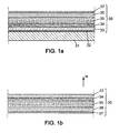
- a layered structure 30 is carried by a support 31.
- the support 31 is chosen from materials having a surface energy which is between 25 mN / m (milliNewton per meter) and 40 mN / m.
- the support 31 is made of polyethylene or polypropylene, which materials have respective surface energies of about 35 mN / m and 30 mN / m.
- the material of the support 31 has a relatively low surface energy, so that the layered structure 30 can be easily separated from the support 31, for example by peeling.
- an intermediate layer 32 is made between the support 31 and the structure 30, to facilitate a separation between the structure 30 and the support 31.
- Such an intermediate layer 32 is called a peel layer and may comprise, in particular, a tensio compound. silicone-based active ingredient.
- Figure 1b shows the layered structure 30, after it has been separated from the support 31.
- the support 31 is called temporary support. It is used to make the layered structure 30, and is removed before the structure 30 is applied to an optical element.
- the layered structure 30 comprises five elementary layers, referenced 33 to 37.
- the layer 33 which is formed first on the support 31 or over the peel layer 32, is intended to impart a specific function to the optical element on which the structure 30 will be transferred. It may be, for example, a UV protection layer, an oxygen barrier layer, an anti-abrasion layer, an anti-shock layer, an anti-reflective coating, an anti-static coating or an anti-fouling coating. Optionally, the layer 33 may be a combination of several of the preceding layers or coatings.
- the layer 33 then forms part of the structure 30 which is intended to be separated from the support 31, to form a self-supporting membrane according to the invention.
- the layer 33 may in particular make it possible to reinforce the mechanical properties of the layer structure (34, 35) and thus facilitate its handling as a self-supported membrane.
- the layer 34 which is located on the layer 33 within the structure 30, is formed of an anisotropic polymer network which induces an orientation of the compounds of the layer 35.
- Dichroic dyes which are incorporated in the layer 35 thus have an orientation which is determined by the layer 34.
- the polarizing effect of the structure 30 is all the more important as the distribution of the angular orientations of the dichroic dyes in the layer 35 is tightened around the direction determined by the layer 34.
- the layer 34 comprises photo-orientable polymers having photo-reactive groups, which, after reaction under linearly polarized light, form an anisotropic polymer network oriented according to direction of the polarizer.
- the layer 34 is formed on the support 31, already provided with the layers 32 and 33, from polymers bearing photo-reactive cinnamic acid groups. This polymer is dissolved for example in a solvent of methyl ethyl ketone, cyclohexanone or a mixture of these two last solvents. The surface energy of the material on which layer 34 is formed is adjusted so as to obtain a continuous layer 34 of uniform thickness.
- the solvent is then evaporated, for example by means of infrared radiation or by passing through an oven, and the layer 34 is polymerized under the effect of UV-B type radiation.
- the UV-B radiation that is used is polarized linearly by a polarizer. This radiation can have an energy which is between 5 and 300 mJ / cm 2 (milliJoule per centimeter-square), for example.
- the layer 35 is then formed on the layer 34 from a mixture of crosslinkable monomeric liquid crystals and dichroic dyes distributed in a solvent.
- dichroic dyes may be selected to impart color to the structure, and subsequently to provide the final optical element with a sunscreen function.
- the monomeric liquid crystals and the dichroic dyes of the layer 35 on the layer 34 can be mixed with a solvent such as cyclohexanone for example.
- the layer 35 is heated and then polymerized under the effect of UV-A radiation. During heating, the monomeric liquid crystals take an orientation which is determined by the orientation of the photo-oriented polymer network of the layer 34 and which is perpendicular to it.
- the heating temperature may for example be 87 ° C.
- the heating and drying step can be carried out within one and the same step of the overall process.
- the heating temperature will strongly depend on the type of liquid crystal used. During this step, the clarification temperature of the liquid crystals must not be exceeded. Beyond this temperature, the liquid crystals are no longer oriented in a preferred direction.
- the thickness of the layer 34 may be between 50 and 200 nm (nanometer), and is preferably equal to about 140 nm.
- the thickness of the layer 35 may be between 3 and 100 microns (micrometers), preferably between 5 and 50 microns, and preferably between 5 and 10 microns.
- the mechanical behavior of the structure 30 is mainly provided by the layer 35.
- the energy of the polymerization radiation of the layer 35 is preferably comprised between 0.3 and 1.5 J (Joule), or even between 0.35 and 0.8 J. In particular, when the energy of the radiation is substantially equal to 0.4 J, the layer 35 which is obtained has a temperature of Tg lower than 25 ° C.
- the structure 30 has a mechanical cohesion which allows it to be handled separately from the support 31 without tearing it apart.
- the layers 34 and 35 may be formed on the support 31 by centrifugation (spin-coating), by roll-coating or by spray-coating,
- the structure 30 may further comprise a layer of an adhesive material 36. It may be an epoxy-based layer, based on a latex, in particular based on polyurethane, or on a pressure-sensitive adhesive material, or PSA for "Pressure Sensitive Adhesive" in English. It preferably has a constant thickness, so as not to subsequently modify an optical power of the optical element.
- the layer of adhesive material 36 may be covered with a film 37, or "liner" in English, to be removed to discover the adhesive surface of the layer 36 before the structure 30 is applied to the optical element.
- the layer 36 may also be formed by spin-coating on the layers 33-35, carried by the support 31. Their formation is considered known by those skilled in the art, and is not repeated here in detail.
- the layer 36 initially associated with the film 37 in a manner independent of the other layers of the structure 30.
- the layer 36 thus conditioned is applied to the layer By pressing through the film 37.
- An identical configuration of the structure 30 can be obtained in this way.
- the layered structure 30 is produced continuously on a support 31 in the form of a film (sheet).
- a production facility as shown in Figure 2 can be used.
- the support 31 is unwound from a supply reel R0, then rolled up again on a conditioning reel R1.
- the installation comprises several sections arranged between the coils R0 and R1, to continuously form the layers 34 and 35 (optionally 33), in particular.
- a first part of the installation may comprise sections S1-S3 for continuously depositing the precursor solution of the layer 34 on the support 31 (section S1), to heat it (section S2), for example by means of an infrared radiation source disposed above the support 31, and then for polymerizing it by linearly polarized UV-B irradiation (section S3).
- a second part of the installation may comprise sections S4-S6, respectively to deposit (section S4), to heat (section S5) and to polymerize (section S6) layer 35.
- Such a continuous production facility of the layered structure 30 may comprise additional sections not shown in FIG. 2, to perform additional manufacturing steps. It may comprise in particular one or more sections for forming the peel layer 32 and / or the functional layer 33. Such sections are arranged between the supply reel R0 and the section S1.
- the solvent used to deposit the peel layer 32 may be n-propanol, when this layer comprises silicone compounds.
- the production facility of the structure 30 may also include additional sections disposed between the section S6 and the conditioning roll R1, to form the layer of adhesive material 36 and, optionally, the removable film 37.
- the production facility may optionally include rolling sections before section S1 and / or after section S6.
- the invention is described in the context of the application of the previous layer structure to an ophthalmic lens which constitutes the basic optical element. It is understood that it can be implemented in a similar manner with other optical elements, such as, in particular, a sighting instrument element, a measuring instrument element or a helmet visor.
- an ophthalmic lens 20 has a convex surface 21 and a concave surface 22. It can be made of mineral or organic material, in particular an organic material with a high refractive index.
- the term "high refractive index” means an index greater than or equal to 1.60, which may be equal to 1.67, for example.
- the use of such a high refractive index material for the production of an ametropic correction lens is particularly advantageous, since the lens can then have a reduced thickness and a lower curvature, for an identical optical power. A lower weight of the lens results, which provides greater comfort to the wearer.
- such an ophthalmic lens may have a thickness of less than 1.2 mm in a central zone thereof, or even substantially equal to 1.1 mm.
- the layered structure 30 is applied to the convex front face 21 of the lens 20 by way of example to illustrate this first method of application, but the structure 30 can be applied in a similar way to the concave posterior face 22 of the lens.
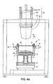
- a device as described in the patent application FR / 05 03306 and illustrated in Figure 4a may be used.
- Such a device comprises a low pressure chamber 1 and an application system 15 disposed above the enclosure via a rigid structure.
- the low-pressure chamber 1 itself comprises a lateral wall 4, for example cylindrical with a vertical axis. It is provided with a clamping ring 8, to firmly hold a membrane on the peripheral edge 4.
- the enclosure 1 is thus sealingly closed on its upper face.
- the enclosure 1 is disposed above a base 10 at a fixed height.
- a cylinder 2 of vertical axis and a piston 3 which passes through the lower face of the chamber 1 can move vertically an element holder 7 inside the enclosure 1.
- a locking system 6 allows to fix the height of the element holder 7, and the wall 4 is provided with a gas inlet 9, as well as a suction port 5.
- the orifice 5 is connected to a pumping unit not shown.
- the application system 15 comprises a buffer 11 mounted on vertical slides 13, and movable by means of a displacement system 12.
- a displacement system may comprise a stepper motor which drives a translation screw, for example.
- the layered structure 30 is fixed on the enclosure 1 by means of the ring 8. It is oriented so that the layer of adhesive material 36 is turned towards the interior of the enclosure 1, in accordance with the vertical direction oriented N which is indicated in Figures 1b and 4a. At this time, if the structure 30 includes a film 37 covering the layer 36, this film 37 is removed, for example by peeling, so as to discover the adhesive material of the layer 36.
- the lens 20 is fixed on the element holder 7, so that its face 21 is oriented upwards.
- the application of the layered structure 30 to the lens 20 can then be carried out by bringing the structure 30 and the lens 20 closer together in several steps.
- a first step the pad 11 is lowered so as to push a central portion of the structure 30 towards the inside of the enclosure 1. Since the structure 30 is held firmly on its periphery by the ring 8 , the structure 30 is deformed and takes a curved shape, which corresponds to that of the lower end of the buffer 11. When the structure 30 exhibits a plastic behavior, this first step constitutes a preforming the layered structure, so that it can then be applied regularly to the curved surface 21 of the lens 20.
- the lens 20 is approached to the layered structure 30 creating a depression between them, inside the chamber 1.
- the piston 3 rises as a gas initially present in the chamber 1 is sucked by the orifice 5.
- the height of the piston 3 is then fixed by means of the blocking 6.
- the pad 11 is again lowered by pressing it on the layered structure 30, on one side thereof opposite the lens 20.
- the structure 30 is applied on the entire surface 21 of the lens 20, with the layer of adhesive material 36 clamped therebetween.
- the end of the pad 11 is preferably made of a flexible material, so as to obtain a regular application of the structure 30 over the entire surface 21 of the lens.
- the buffer 11 is then raised, the suction in the chamber 1 is stopped and the ring 8 is unlocked.
- the lens 20 is removed from the device with the structure 30 bonded through the adhesive layer 36, on its convex face, perfectly marrying the geometry of the basic optical element, optionally, a new irradiation of the layer 35 can be performed with UV-A radiation energy of 0.5 to 5.0 J to complete the polymerization of the overall system.
- a polymerization of the entire system makes it possible to benefit from a suitable mechanical behavior of the structure 30 during its application to the ophthalmic lens.
- Such final irradiation may also make it possible to enhance the stability of the system due to an increase in the conversion rate of the constituent elements.
- a polarizing ophthalmic lens which has a high polarization efficiency is then obtained, and which has a satisfactory optical quality.
- the inventors have found that the application of the structure 30 to the lens 20 does not disturb the orientation of the dichroic dyes inside the layer 35.
- the use of a depression inside the enclosure 1 during the application of the structure 30 to the glass 20 helps to prevent a gaseous bubble being trapped involuntarily, between the layered structure and the glass.
- the layered structure 30 comprises a functional layer 33 situated within the structure, on a side opposite to the layer of adhesive material 36, the layer 33 is located on the surface of the obtained polarizing lens, on an opposite side.
- This configuration is suitable when the layer 33 has a protective function against UV radiation, a mechanical protection function, an anti-reflective function or an antifouling function.
- the portion of adhesive material which ensures the attachment of the layered structure on the base optical element may be initially arranged on this element, on the face thereof which is intended to receive the layered structure.
Landscapes
- Engineering & Computer Science (AREA)
- Manufacturing & Machinery (AREA)
- Mechanical Engineering (AREA)
- Physics & Mathematics (AREA)
- Health & Medical Sciences (AREA)
- Ophthalmology & Optometry (AREA)
- General Physics & Mathematics (AREA)
- Optics & Photonics (AREA)
- Polarising Elements (AREA)
Abstract
Description
- La présente invention concerne un procédé de réalisation d'un élément optique polarisant, ainsi qu'un élément optique obtenu par ce procédé. Elle concerne encore une structure en couches utile pour réaliser un tel élément optique polarisant.
- Les bénéfices des éléments optiques polarisants, et tout particulièrement des lentilles ophtalmiques polarisantes, sont bien connus. En particulier, de tels éléments peuvent supprimer du champ de vision des réflexions parasites qui proviennent de surfaces planes ou quasi-planes horizontales. Ce type de lentilles, par exemple, est obtenu de façon classique dans l'industrie ophtalmique à l'aide d'un film polarisant. Le matériau le plus classiquement utilisé pour fabriquer des films polarisants est le PVA (Polyvinyl Alcool). Pour les applications ophtalmiques, le film de PVA est utilisable seul ou pris en sandwich entre deux films de protection de façon à former un film composite moins délicat, par exemple entre deux films de Polycarbonate.
- La lentille ophtalmique polarisante est alors obtenue selon deux voies classiques dans l'industrie :
- Par surmoulage, en positionnant précisément le film polarisant dans un moule avant coulée d'un monomère thermodurcissable. Après polymérisation, le film se trouve incorporé de façon définitive dans le volume du substrat de la lentille ophtalmique. Les films de PVA seul sont utilisés pour cela.
- Par injection, en positionnant le film polarisant à la surface d'un insert avant injection d'un polymère thermoplastique. Une telle technique n'est possible que si la face du film polarisant en contact avec le polymère injecté est un matériau thermoplastique compatible, c'est-à-dire apte à fusionner avec le matériau injecté pour donner un assemblage durable. Elle s'applique notamment à des films composites qui sont des empilements à base d'un film de PVA positionné entre deux films de protection, et qui peuvent être thermoformés avant d'être positionnés dans l'insert. En outre, le film de protection qui recouvre le film polariseur du côté opposé à l'élément optique en matériau injecté ne doit pas présenter de biréfringence importante car, dans ce cas, l'efficacité de polarisation de l'élément optique qui est finalement obtenu peut être réduite. Ceci limite la variété de film polariseur pouvant être mise en oeuvre dans ce type de procédé.
- Dans les deux procédés, surmoulage et injection, le chauffage du film polarisant provoque une altération de celui-ci. En particulier, sa couleur et son efficacité de polarisation sont modifiées involontairement et de façon peu reproductible. En outre, il est difficile d'empêcher que des déplacements incontrôlés du film polarisant ne se produisent pendant le surmoulage.
- Enfin, le procédé par surmoulage ne permet pas d'obtenir un élément optique qui présente une épaisseur totale réduite optimisée. Ceci est particulièrement gênant pour les matériaux à haut indice de réfraction.
- Un but de la présente invention consiste donc à proposer un procédé de réalisation d'un élément optique polarisant, qui ne présente pas les inconvénients cités ci-dessus.
- Pour cela, l'invention propose un procédé de réalisation d'un élément optique polarisant, suivant lequel une structure en couches est appliquée sur une surface d'un élément optique de base. La structure comprend une première couche d'orientation, qui comprend elle-même un réseau de polymères photo-orientés. Elle comprend en outre une seconde couche polarisante, qui comprend à son tour des polymères à cristaux liquides et au moins un colorant dichroïque, ceux-ci ayant une orientation angulaire qui est déterminée par la première couche. Le procédé comprend les étapes suivantes :
- /a/ réaliser la structure en couches sur un support temporaire ;
- /b/ retirer la structure en couches du support temporaire, de façon à obtenir la structure sous forme d'une membrane auto-supportée ; et
- /c/ appliquer la structure en couches sur la surface pseudo-sphérique de l'élément optique de base.
- Au sens de l'invention, par surface de l'élément optique de base, on entend l'ensemble de la surface de cet élément ou au moins une partie de sa surface. Selon une caractéristique de l'invention, cette surface de l'élément optique de base est pseudo-sphérique.
- Dans le cadre de l'invention, on entend par surface pseudo-sphérique une surface concave ou convexe continue, c'est-à-dire une surface qui est dépourvue de trous ou de marches. De telles surfaces pseudo-sphériques sont notamment rencontrées lorsque l'élément optique est une lentille optique. En général, au moins l'une des deux faces d'une lentille optique est pseudo-sphérique, de sorte que la variation d'épaisseur de la lentille qui en résulte lui confère un pouvoir optique. Des lentilles ophtalmiques afocales, unifocales, bifocales, trifocales et progressives ont toutes au moins une face pseudo-sphérique. Une surface sphérique correspond à un cas particulier de surface pseudo-sphérique, pour lequel des rayons de courbure de la surface selon deux directions perpendiculaires sont égaux et uniformes. Dans la suite, l'expression «surface pseudo-sphérique» est entendue comme incluant le cas particulier des surfaces sphériques.
- Ainsi, la structure en couches, qui confère la fonction polarisante à l'élément optique, est d'abord réalisée sur un support temporaire, puis séparée de celui-ci et appliquée sur l'élément optique de base. Cette séquence est rendue possible grâce au fait que la structure en couches est suffisamment cohésive pour être manipulée isolément, c'est-à-dire sans être soutenue par aucun support. Les propriétés mécaniques et physico-chimiques du support temporaire n'interviennent donc pas lors de l'application de la structure en couches sur l'élément optique de base. Cette application peut donc être réalisée simplement, en ne prenant en compte que le comportement mécanique de la structure en couches, sans tenir compte de celui du support temporaire.
- Un premier avantage d'un procédé selon l'invention réside dans la possibilité de réaliser un élément optique polarisant dont l'épaisseur est optimisée. En effet, la structure en couches est simplement appliquée sur une surface de l'élément optique, ce qui n'augmente pas notablement l'épaisseur de celui-ci.
- Un second avantage d'un procédé selon l'invention réside dans le fait que la structure en couches peut être produite sur le support temporaire sous forme d'un film continu. Une quantité importante de la structure en couches peut ainsi être fabriquée de façon économique, par circulation du support temporaire à travers des sections de fabrication successives. La structure, une fois désolidarisée de son support, peut ensuite être découpée en segments qui sont appliqués individuellement sur des éléments optiques distincts. Alternativement, la structure peut être appliquée dans son intégralité en une seule fois sur plusieurs éléments distincts, puis les éléments peuvent être séparés les uns des autres par la suite.
- Un troisième avantage selon l'invention est que la production du film polarisant est totalement détachée de la production de l'élément optique. Ceci est particulièrement intéressant pour le secteur des lentilles ophtalmiques.
- Un quatrième avantage selon l'invention est lié au fait que l'application de la structure en couches à propriété polarisante sur la surface d'un élément optique déjà constitué permet de faire épouser parfaitement le profil de la surface réceptrice à la structure polarisante, avec ainsi un très bon contrôle de la distance séparant la surface de la structure en couches de la surface de l'élément optique. Ceci est particulièrement bénéfique pour garantir des propriétés dioptriques particulières pour l'élément optique polarisant finalement obtenu, notamment dans le cas où l'élément optique polarisant est une lentille ophtalmique de type lentille progressive, dont le rayon de courbure varie continûment sur sa surface.
- Un cinquième avantage du procédé selon l'invention provient du fait que le support temporaire peut être récupéré après que la structure en couches a été séparée de celui-ci à l'étape /b/. Eventuellement, le support récupéré peut être réutilisé pour fabriquer une nouvelle portion de structure en couches.
- Selon une autre caractéristique de l'invention, l'étape /a/ du procédé comprend les sous-étapes suivantes :
- /a1/ former, sur le support temporaire, une première couche de polymères photo-orientables, qui présentent des groupes photo-réactifs ;
- /a2/ polymériser la première couche sous un premier rayonnement ultraviolet polarisé linéairement, de façon à réaliser un réseau de polymère photo-orienté selon une direction qui est imposée par la direction de polarisation de ce premier rayonnement ultraviolet ;
- /a3/ ormer, sur cette première couche, une seconde couche qui comprend un mélange des colorants dichroïques avec au moins un cristal liquide monomérique réticulable, ceux-ci étant orientés angulairement par la première couche ; et
- /a4/ polymériser au moins en partie les cristaux liquides monomériques de la seconde couche, de façon à fixer les colorants dichroïques dans l'orientation angulaire déterminée par la première couche.
- La polarisation linéaire du premier rayonnement ultraviolet peut être réalisée au moyen d'un polariseur qui est intercalé entre une source de ce premier rayonnement et la première couche.
- Lors de la sous-étape /a2/, la réaction, sous l'effet du rayonnement polarisé, des groupes photo-réactifs qui sont portés par le polymère photo-orientable conduit à la formation d'un réseau de polymère anisotrope, orienté selon la direction du polariseur.
- Dans la seconde couche du système polarisant, les cristaux liquides monomériques et les colorants dichroïques peuvent adopter, lors de l'étape /a3/, une orientation qui est perpendiculaire à la direction du polariseur, qui a été imposée au polymère photo-orientable de la première couche. Cette orientation des colorants dichroïques confère au système les propriétés de polarisation de la lumière visible. La polymérisation des cristaux liquides monomériques, à l'étape /a4/, stabilise ensuite définitivement la configuration de la seconde couche.
- Selon encore une autre caractéristique de l'invention, la polymérisation de la seconde couche à la sous-étape /a4/ est réalisée en utilisant une dose d'un second rayonnement ultraviolet qui est ajustée de sorte que la seconde couche possède une température de transition vitreuse inférieure ou égale à la température ambiante. Il est entendu que la température ambiante considérée peut varier, notamment de plus ou moins 5°C. En générale, elle est proche de 25°C. Autrement dit, la quantité du rayonnement ultraviolet qui est utilisée à la sous-étape /a4/ permet de sélectionner un degré de polymérisation de la seconde couche, et par conséquent d'ajuster ses propriétés thermo-mécaniques. Ainsi, une sous-polymérisation aboutit à une seconde couche qui présente une température de transition vitreuse (Tg) qui est inférieure à celle qui serait obtenu à l'issue d'une polymérisation complète. On entend par sous-polymérisation une polymérisation partielle, avec un degré de polymérisation tel qu'une partie des fonctions polymérisantes de la seconde couche n'a pas encore réagi. De telles fonctions polymérisantes peuvent être, notamment, des fonctions acrylate ou méthacrylate. Selon l'invention, la dose de second rayonnement ultraviolet doit être suffisamment élevée pour que le point de gel chimique du polymère en croissance soit atteint, tout en restant suffisamment faible pour que la température de transition vitreuse du matériau final de la seconde couche soit adaptée par rapport à la température de mise en oeuvre de la structure en couches:
- Lorsque la dose d'irradiation de la seconde couche est telle que le matériau qui est obtenu après l'étape de pré-polymérisation a une température de transition vitreuse inférieure à la température ambiante, ce matériau possède, à température ambiante, des propriétés mécaniques qui permettent de le manipuler et de l'appliquer facilement sur l'élément optique de base.
- Avantageusement, la seconde couche possède une épaisseur comprise entre 3 et 100 µm (micromètre), préférentiellement entre 5 et 50 µm, et plus particulièrement entre 5 et 10 µm. Dans ces conditions, la seconde couche peut conférer à l'ensemble de la structure en couches une cohésion mécanique suffisante pour que la structure puisse être manipulée sous forme d'une membrane auto-supportée, notamment pour l'étape /c/.
- Parmi les polymères réactifs photo-orientables utilisables dans le cadre de l'invention on peut citer à titre indicatif, ceux étant formé à partir de polymère acrylique, methacrylique, de polyimides, et de dendrimères. Les polymères réactifs photo-orientables présentant des groupes photoréactifs tels que acide cinnamique et ses dérivés, chalcones, coumarines, ou des ponts méthacrylates sont particulièrement envisageables.
- Parmi les colorants dichroïques utilisables dans le cadre de l'invenion on peut citer à titre indicatif, les azométhines, les indigoïdes, les thioindigoïdes, les indanes, les quinophtaloniques, les perylènes, les phtalopérines, les triphenodioxazines, les indoloquinoxalines, les imidazotriazines, les colorants azo et polyazo, les benzoquinones, les naphtoquinones, les anthraquinones et (poly)anthraquinones, les anthrapyrimidinones, les iodines et les iodates. Avantageusement les azos colorants et les anthraquinones sont tuilisés dans le cadre de l'invention.
- La structure en couches peut être appliquée à l'étape /c/ sur la surface de l'élément optique de base avec une portion d'un matériau adhésif disposée entre la structure et cet élément. Une telle utilisation d'un matériau adhésif permet de mettre en oeuvre un procédé selon l'invention pour des éléments optiques de base qui ont des compositions chimiques différentes, au niveau de la surface sur laquelle la structure en couches est appliquée. Ce matériau adhésif, dans le cadre de l'invention peut être appliqué sur une face de l'élément optique et/ou sur la structure en couche. De préférence, avant l'étape /c/, la portion de matériau adhésif est disposée sous forme d'une couche supplémentaire de la structure en couches sur un côté de ladite structure. Avec une telle couche de matériau adhésif, la structure en couches contient tous les composants nécessaires pour apporter une fonction polarisante à un élément optique quelconque. Il suffit donc de se procurer la structure en couches pour réaliser un élément optique polarisant à partir d'un élément optique simple.
- Parmi les matériaux adhésifs utilisables dans le cadre de l'invention, on peut citer à titre indicatif et non limitatif : les adhésifs époxydes, les adhésifs polyuréthanes réactifs; les colles thermodurcissables; les adhésifs à base de monomères polymérisables tels que les adhésifs cyanoacrylates; les adhésifs acryliques structuraux ou acryliques modifiés; les adhésifs "hot melts" ou thermofusibles; les plastisols PVC (polychlorure de vinyle); les adhésifs élastomères, colle contact au néoprène; les colles émulsions vinyliques et copolymères; les adhésifs sensibles à la pression (PSA); les colles à l'eau.
- Selon un mode de réalisation de l'invention, l'utilisation d'une couche de matériau adhésif sensible à la pression, ou PSA pour «Pressure Sensitive Adhesive» en anglais, est particulièrement avantageuse car elle permet de coller sur la surface de l'élément optique de base la structure en couche de façon simple et peu coûteuse, tout en préservant les propriétés dioptriques de l'élément optique.
- De plus, la possibilité de déposer le matériau adhésif PSA sous forme d'une couche fine à faces parallèles dont l'épaisseur peut être comprise entre 0,5 et 200 microns permet, lorsque l'élément optique de base est une lentille ophtalmique, de ne pas altérer sa puissance nominale quelle que soit la zone spatiale concernée de l'élément optique. De cette façon, le collage du film polariseur est compatible avec la précision qui est nécessaire lorsque l'élément optique de base est une lentille ophtalmique progressive.
- L'utilisation d'un matériau adhésif sensible à la pression ne nécessite pas d'utiliser une irradiation, par exemple par un rayonnement ultraviolet, ni un chauffage intensif pour obtenir un collage permanent. Ainsi, la structure en couche polarisante n'est pas altérée ni dégradée par une telle irradiation ou chauffage.
- L'invention propose aussi une structure en couches qui est adaptée pour être utilisée dans un procédé tel que décrit précédemment. Une telle structure comprend :
- une première couche d'orientation, qui comprend un réseau de polymères photo-orientés ; et
- une seconde couche polarisante sous-polymérisée, qui comprend au moins un colorant dichroïque et une matrice d'au moins un cristal liquide monomérique réticulable, adaptée pour fixer une orientation angulaire des colorants dichroïques.
- Les colorants dichroïques ont une orientation angulaire qui est déterminée par la première couche de façon à produire un effet polarisant de la seconde couche pour une lumière transmise à travers la structure. Cette orientation est fixée définitivement en incorporant les colorants dichroïques au sein de la matrice de cristaux liquides monomériques réticulables.
- En outre, les première et seconde couches sont adaptées pour former une membrane auto-supportée.
- Une telle structure en couches peut être disposée sur un support, de façon à pouvoir être séparée de ce dernier. II peut s'agir d'un support utile lors de la fabrication de la structure. De plus il peut servir à conditionner la structure entre la fabrication de celle-ci et son utilisation ultérieure avec un élément optique.
- La structure en couches peut comprendre en outre une couche de matériau adhésif. La portion de matériau adhésif est disposée sous forme d'une couche supplémentaire de la structure en couches Elle peut comprendre encore au moins une autre couche fonctionnelle, destinée à apporter une fonction supplémentaire à l'élément optique, en même temps que la fonction de polarisation.
- L'invention propose enfin un élément optique polarisant qui comprend un élément optique de base et une structure en couches telle que décrite ci-dessus. Cette structure en couches est fixée sur une surface pseudo-sphérique de l'élément optique de base par une couche d'un matériau adhésif disposée entre l'élément de base et la structure en couches. Elle confère à l'élément optique une fonction polarisante pour une lumière transmise à travers cet élément.
- D'autres particularités et avantages de la présente invention apparaîtront dans la description ci-après d'exemples de mise en oeuvre non limitatifs, en référence aux dessins annexés, dans lesquels :
- les figures 1a et 1b sont des vues en coupe d'une structure en couches portée par un support et isolée de celui-ci, respectivement, telle qu'utilisée dans une mise en oeuvre de la présente invention ;
- la figure 2 illustre le principe d'une unité de production d'une structure en couches conforme aux figures 1a et 1b ;
- la figure 3 est une vue en coupe d'un élément optique de base pouvant être utilisé pour mettre en oeuvre l'invention ; et
- les figures 4a et 4b sont des vues en coupe respectives de deux dispositifs utilisés pour mettre en oeuvre l'invention.
- Pour raison de clarté des figures, les dimensions des éléments représentés ne sont pas en proportion avec des dimensions ou des rapports de dimensions réels. En outre, des références identiques dans des figures distinctes désignent des éléments identiques, ou qui ont des fonctions identiques.
- Conformément à la figure 1a, une structure en couches 30 est portée par un support 31. Le support 31 est choisi parmi les matériaux ayant une énergie de surface qui est comprise entre 25 mN/m (milliNewton par mètre) et 40 mN/m. Parmi ces matériaux on peut citer à titre indicatif, et non limitatif, les poly(éthylène) branchés ou linéaires, les poly(éthylène-stat-acide acrylique) dont le pourcentage en mole d'acide acrylique est inférieur ou égal à 2%, les poly(éthylène-stat-polypropylène), les poly(éthylène-stat-acétate de vinyl), les poly(isobutène), les poly(isoprène), les poly(4-méthyl-1-pentène), les poly(propylène), les poly(2-methylstyrène), les poly(styrène), les poly(styrène-stat-acylonitrile), les poly(styrène-stat-2,2,3,3-tétrafluoropropyl métharcrylate), les poly(chlorotrifluoroethylène), les poly(chlorotrifluoroéthylène-stat-tetrafluoroéthyène), les poly(tetrafluoroethylène-stat-ethylène), les poly(trifluoroethylène), les poly(vinyl chloride), les poly(vinyl fluoride), les poly(vinylidène fluoride), les poly(vinyl acétate), les poly(vinyl(alkyl)oate), les poly(vinyl alcool), les poly(vinyl butyral), les poly(vinyl éthyl éther) les poly(vinyl méthyl éther), les poly(vinyl formal), les poly(n-butyl acrylate), les poly(éthyl acrylate), les poly(2-éthylhexyl acrylate), les poly(benzyl méthacrylate), les poly(alkyl méthacrylate), les poly(phényl méthacrylate), , les polyamides, les polyuréthane, les cellulosique.
- D'une façon avantageuse, le support 31 est en polyéthylène ou en polypropylène, lesquels matériaux présentent des énergies de surfaces respectives d'environ 35 mN/m et 30 mN/m.
- De préférence, le matériau du support 31 présente une énergie de surface assez faible, de sorte que la structure en couches 30 puisse être aisément séparée du support 31, par exemple par pelage. Eventuellement, une couche intermédiaire 32 est réalisée entre le support 31 et la structure 30, pour faciliter une séparation entre la structure 30 et le support 31. Une telle couche intermédiaire 32 est appelée couche de pelage et peut comprendre, en particulier, un composé tensio-actif à base de silicone.
- La figure 1b représente la structure en couches 30, après qu'elle a été séparée du support 31. Pour cette raison, le support 31 est appelé support temporaire. Il est utilisé pour réaliser la structure en couches 30, puis est retiré avant que la structure 30 soit appliquée sur un élément optique.
- Dans le mode de mise en oeuvre de l'invention qui est décrit ici, la structure en couches 30 comprend cinq couches élémentaires, référencées 33 à 37.
- La couche 33, qui est formée en premier sur le support 31 ou par dessus la couche de pelage 32, est destinée à conférer une fonction spécifique à l'élément optique sur lequel la structure 30 sera transférée. Ce peut être, par exemple, une couche de protection contre un rayonnement UV, une couche barrière à l'oxygène, une couche anti-abrasion, une couche anti-choc, un revêtement antireflet, un revêtement anti-statique ou un revêtement antisalissure. Eventuellement, la couche 33 peut être une combinaison de plusieurs des couches ou revêtements précédents. La couche 33 fait alors partie de la structure 30 qui est destinée à être séparée du support 31, pour former une membrane auto-supportée selon l'invention. La couche 33 peut notamment permettre de renforcer les propriétés mécaniques de la structure en couche (34, 35) et faciliter ainsi sa manipulation en tant que membrane auto-supportée.
- La couche 34, qui est située sur la couche 33 au sein de la structure 30, est formée d'un réseau de polymère anisotrope qui induit une orientation des composés de la couche 35. Des colorants dichroïques qui sont incorporés dans la couche 35 ont ainsi une orientation qui est déterminée par la couche 34. II en résulte un effet polarisant macroscopique de la structure 30, pour un faisceau lumineux qui traverse celle-ci. De façon connue, l'effet polarisant de la structure 30 est d'autant plus important que la répartition des orientations angulaires des colorants dichroïques dans la couche 35 est resserrée autour de la direction déterminée par la couche 34.
- La couche 34 comprend des polymères photo-orientables présentant des groupes photo-réactifs, qui, après réaction sous lumière polarisée linéairement, forment un réseau de polymère anisotrope orienté selon la direction du polariseur. Par exemple, la couche 34 est formée sur le support 31, déjà muni des couches 32 et 33, à partir de polymères portant des groupements photo-réactifs acide cinnamique. Ce polymère est dissous par exemple dans un solvant de méthyl-éthyl-cétone, de cyclohexanone ou dans un mélange de ces deux derniers solvants. L'énergie de surface du matériau sur lequel est formée la couche 34 est ajustée de façon à obtenir une couche 34 continue et d'épaisseur régulière. Le solvant est ensuite évaporé, par exemple au moyen d'un rayonnement infrarouge ou par passage dans une étuve, et la couche 34 est polymérisée sous l'effet d'un rayonnement de type UV-B. Pour provoquer une polymérisation de la couche 34 sous forme d'un réseau de polymère photo-orienté, le rayonnement UV-B qui est utilisé est polarisé linéairement par un polariseur. Ce rayonnement peut avoir une énergie qui est comprise entre 5 et 300 mJ/cm2 (milliJoule par centimètre-carré), par exemple.
- La couche 35 est ensuite formée sur la couche 34 à partir d'un mélange de cristaux liquides monomériques réticulables et de colorants dichroïques répartis dans un solvant. Eventuellement, les colorants dichroïques peuvent être sélectionnés pour conférer une coloration à la structure, et, ultérieurement, pour conférer à l'élément optique final une fonction de filtre solaire. Les cristaux liquides monomériques et les colorants dichroïques de la couche 35 sur la couche 34 peuvent être mélangés à un solvant tel que la cyclohexanone par exemple. La couche 35 est chauffée puis polymérisée sous l'effet d'un rayonnement UV-A. Lors du chauffage, les cristaux liquides monomériques prennent une orientation qui est déterminée par l'orientation du réseau de polymères photo-orientés de la couche 34 et qui est perpendiculaire à celle-ci. La température de chauffage peut par exemple être de 87°C. Naturellement l'étape de chauffage et de séchage peuvent être réalisées au sein d'une même étape du procédé globale. La température de chauffage va fortement dépendre du type de cristaux liquide utilisé. Lors de cette étape il ne faut pas dépasser la température de clarification des cristaux liquides. Au-delà de cette température les cristaux liquides ne sont plus orientés suivant une direction privilégiée.
- L'épaisseur de la couche 34 peut être comprise entre 50 et 200 nm (nanomètre), et est préférentiellement égale à 140 nm environ. L'épaisseur de la couche 35 peut être comprise entre 3 et 100 µm (micromètres), préférentiellement entre 5 et 50 µm, et avantageusement entre 5 et 10 µm. Dans ces conditions, le comportement mécanique de la structure 30 est principalement procuré par la couche 35. Pour obtenir un comportement mécanique adapté à la mise en oeuvre de l'invention, l'énergie du rayonnement de polymérisation de la couche 35 est de préférence comprise entre 0,3 et 1,5 J (Joule), voire entre 0,35 et 0,8 J. En particulier, lorsque l'énergie du rayonnement est sensiblement égale à 0,4 J, la couche 35 qui est obtenue possède une température de Tg inférieure à 25°C. La structure 30 présente une cohésion mécanique qui permet de la manipuler séparément du support 31, sans la déchirer.
- Les couches 34 et 35 (et optionnellement 33) peuvent être formées sur le support 31 par centrifugation (spin-coating), par roll-coating ou par spray-coating,
- La structure 30 peut encore comprendre une couche d'un matériau adhésif 36. Ce peut être une couche à base d'époxy, à base d'un latex, notamment à base de polyuréthane, ou en un matériau adhésif sensible à la pression, ou PSA pour «Pressure Sensitive Adhesive» en anglais. Elle possède de préférence une épaisseur constante, afin de ne pas modifier ultérieurement une puissance optique de l'élément optique.
- Optionnellement, la couche de matériau adhésif 36 peut être recouverte d'une pellicule 37, ou «liner» en anglais, destinée à être retirée pour découvrir la surface adhésive de la couche 36 avant que la structure 30 soit appliquée sur l'élément optique.
- La couche 36 peut aussi être formée par spin-coating sur les couches 33-35, portées par le support 31. Leur formation est considérée connue par l'Homme du métier, et n'est pas reprise ici en détail.
- Alternativement, il est possible de se procurer la couche 36 associée initialement avec la pellicule 37, d'une façon indépendante des autres couches de la structure 30. La couche 36 ainsi conditionnée est appliquée sur la couche 35 par pression au travers de la pellicule 37. Une configuration identique de la structure 30 peut être obtenue de cette façon.
- Selon un mode de réalisation préféré de la structure en couches 30, celle-ci est produite en continu sur un support 31 en forme de film (feuille). Dans ce cas, une installation de production telle que représentée sur la figure 2, peut être utilisée. Le support 31 est déroulé d'une bobine d'alimentation R0, puis enroulée de nouveau sur une bobine de conditionnement R1. L'installation comporte plusieurs sections disposées entre les bobines R0 et R1, pour former en continu les couches 34 et 35 (optionnellement 33), notamment. En particulier, une première partie de l'installation peut comprendre des sections S1-S3 pour déposer en continu la solution précurseur de la couche 34 sur le support 31 (section S1), pour la chauffer (section S2), par exemple au moyen d'une source de rayonnement infrarouge disposée au dessus du support 31, puis pour la polymériser par irradiation UV-B polarisé linéairement (section S3). De même, une seconde partie de l'installation peut comprendre des sections S4-S6, respectivement pour déposer (section S4), chauffer (section S5) et polymériser (section S6) la couche 35. Une telle installation permet de produire rapidement et de façon particulièrement économique une structure en couches 30 portée par le support 31. Le support 31 muni de la structure 30, sous forme d'un film continu, peut alors être de nouveau déroulé de la bobine R1, et découpé en segments destinés à être appliqués sur des éléments optiques distincts(.
- Une telle installation de production en continu de la structure en couches 30 peut comprendre des sections supplémentaires non représentées sur la figure 2, pour exécuter des étapes additionnelles de fabrication. Elle peut comprendre notamment une ou plusieurs sections de formation de la couche de pelage 32 et/ou de la couche fonctionnelle 33. De telles sections sont disposées entre la bobine d'alimentation R0 et la section S1. Le solvant utilisé pour déposer la couche de pelage 32 peut être du n-propanol, lorsque cette couche comprend des composés de silicone. L'installation de production de la structure 30 peut aussi comprendre des sections supplémentaires disposées entre la section S6 et la bobine de conditionnement R1, pour former la couche de matériau adhésif 36 et, éventuellement, la pellicule amovible 37. L'installation de production peut optionnellement comprendre des sections de laminages avant la section S1 et/ou après la section S6.
- A titre d'illustration, l'invention est décrite dans le cadre de l'application de la structure à couches précédente sur une lentille ophtalmique qui constitue l'élément optique de base. Il est entendu qu'elle peut être mise en oeuvre de façon similaire avec d'autres éléments optiques, tels que, notamment, un élément d'instrument de visée, un élément d'instrument de mesure ou une visière de casque.
- Conformément à la figure 3, une lentille ophtalmique 20 présente une surface convexe 21 et une surface concave 22. Elle peut être en matériau minéral ou organique, en particulier en un matériau organique à indice de réfraction élevé. Dans le cadre de l'invention, on entend par indice de réfraction élevé un indice supérieur ou égal à 1,60, pouvant être égal à 1,67, par exemple. L'utilisation d'un tel matériau à indice de réfraction élevé pour la réalisation d'une lentille correctrice d'amétropie est particulièrement avantageuse, puisque la lentille peut alors présenter une épaisseur réduite et une courbure moindre, pour une puissance optique identique. Un poids inférieur de la lentille en résulte, qui procure un confort supérieur au porteur. En particulier, une telle lentille ophtalmique peut avoir une épaisseur inférieure à 1,2 mm dans une zone centrale de celui-ci, voire sensiblement égale à 1,1 mm.
- Selon une première méthode d'application la structure en couches 30 est appliquée sur la face antérieure convexe 21 de la lentille 20 à titre d'exemple pour illustrer cette première méthode d'application, mais la structure 30 peut être appliquée de façon similaire sur la face postérieure concave 22 de la lentille.
- Pour cela, un dispositif tel que décrit dans la demande de brevet
FR/05 03306 - L'enceinte à basse pression 1 comprend elle-même une paroi latérale 4, par exemple cylindrique d'axe vertical. Elle est munie d'un anneau de serrage 8, pour maintenir fixement une membrane sur le bord périphérique supérieur la paroi 4. L'enceinte 1 est ainsi fermée de manière étanche sur sa face supérieure. L'enceinte 1 est disposée au dessus d'une embase 10, à une hauteur fixe. Un cylindre 2 d'axe vertical et un piston 3 qui traverse la face inférieure de l'enceinte 1 permettent de déplacer verticalement un porte-élément 7 à l'intérieur de l'enceinte 1. Un système de blocage 6 permet de fixer la hauteur du porte-élément 7, et la paroi 4 est munie d'un orifice d'admission gazeuse 9, ainsi que d'un orifice d'aspiration 5. L'orifice 5 est connecté à une unité de pompage non représentée.
- Le système d'application 15 comprend un tampon 11 monté sur des glissières verticales 13, et déplaçable au moyen d'un système de déplacement 12. Un tel système de déplacement peut comprendre un moteur pas-à-pas qui entraîne une vis de translation, par exemple. Un détecteur de pression 14, qui peut comprendre un élément piézoélectrique, permet de mesurer une force d'application du tampon contre la membrane de fermeture de l'enceinte 1.
- La structure en couches 30 est fixée sur l'enceinte 1 au moyen de l'anneau 8. Elle est orientée de sorte que la couche de matériau adhésif 36 est tournée vers l'intérieur de l'enceinte 1, conformément à la direction verticale orientée N qui est indiquée sur les figures 1b et 4a. A ce moment, si la structure 30 comporte une pellicule 37 de recouvrement de la couche 36, cette pellicule 37 est retirée, par exemple par pelage, de façon à découvrir le matériau adhésif de la couche 36.
- La lentille 20 est fixée sur le porte-élément 7, de sorte que sa face 21 est orientée vers le haut.
- L'application de la structure à couches 30 sur la lentille 20 peut alors être effectuée en rapprochant l'un de l'autre la structure 30 et la lentille20 en plusieurs étapes.
- Lors d'une première étape, le tampon 11 est descendu de façon à repousser une partie centrale de la structure 30 vers l'intérieur de l'enceinte 1. Etant donné que la structure 30 est maintenue fermement sur sa périphérie par l'anneau 8, la structure 30 est déformée et prend une forme courbe, qui correspond à celle de l'extrémité inférieure du tampon 11. Lorsque la structure 30 présente un comportement plastique, cette première étape constitue un préformage de la structure en couches, de sorte que celle-ci peut ensuite être appliquée régulièrement sur la surface courbe 21 de la lentille 20.
- Lors d'une seconde étape, la lentille 20 est approché de la structure en couches 30 en créant une dépression entre ceux-ci, à l'intérieur de l'enceinte 1. Le piston 3 monte au fur et à mesure qu'un gaz initialement présent dans l'enceinte 1 est aspiré par l'orifice 5. Lorsqu'un contact ponctuel est réalisé entre la structure en couches 30 et la surface 21 de la lentille 20, la hauteur du piston 3 est alors fixée au moyen du système de blocage 6.
- Enfin, lors d'une troisième étape, le tampon 11 est de nouveau descendu en le pressant sur la structure en couches 30, d'un côté de celle-ci opposé à la lentille 20. De cette façon, la structure 30 est appliquée sur toute la surface 21 de la lentille 20, avec la couche de matériau adhésif 36 serrée entre celles-ci. L'extrémité du tampon 11 est de préférence constituée d'un matériau souple, de façon à obtenir une application régulière de la structure 30 sur toute la surface 21 de la lentille.
- Le tampon 11 est alors remonté, l'aspiration au sein de l'enceinte 1 est arrêtée et l'anneau 8 est débloqué. La lentille 20 est retirée du dispositif avec la structure 30 collée au travers de la couche adhésive 36, sur sa face convexe, en épousant parfaitement la géométrie de l'élément optique de base, Eventuellement, une nouvelle irradiation de la couche 35 peut être effectuée, avec une énergie de rayonnement UV-A comprise entre 0,5 et 5,0 J, pour terminer la polymérisation du système globale. Une telle polymérisation de l'ensemble du système permet de bénéficier d'un comportement mécanique adapté de la structure 30 pendant son application sur la lentille ophtalmique. Une telle irradiation finale peut aussi permettre de renforcer la stabilité du système du fait d'une augmentation du taux de conversion des éléments constitutifs.
- Une lentille ophtalmique polarisant qui présente une efficacité de polarisation élevée est alors obtenu, et qui présente une qualité optique satisfaisante. En particulier, les inventeurs ont constaté que l'application de la structure 30 sur la lentille 20 ne perturbe pas l'orientation des colorants dichroïques à l'intérieur de la couche 35.
- En outre, l'utilisation d'une dépression à l'intérieur de l'enceinte 1 pendant l'application de la structure 30 sur le verre 20 contribue à éviter qu'une bulle gazeuse soit emprisonnée involontairement, entre la structure en couches et le verre.
- Lorsque la structure en couches 30 comprend une couche fonctionnelle 33 située, au sein de la structure, d'un côté opposé à la couche de matériau adhésif 36, la couche 33 est située à la surface du verre polarisant obtenu, d'un côté opposé au verre 20 par rapport aux couches 34 et 35. Une telle configuration est adaptée lorsque la couche 33 possède une fonction de protection contre un rayonnement UV, une fonction de protection mécanique, une fonction antireflet ou une fonction anti-salissure.
- II est entendu que de nombreuses modifications peuvent être introduites dans les exemples de mise en oeuvre de l'invention qui ont été décrits en détail ci-dessus, tout en conservant certains au moins des avantages de l'invention. De telles modifications peuvent permettre, notamment, d'adapter ces exemples à des utilisations particulières de l'élément optique, ou à des éléments optiques autres qu'un verre ophtalmique. En particulier, la portion de matériau adhésif qui assure la fixation de la structure à couches sur l'élément optique de base peut être disposée initialement sur cet élément, sur la face de celui-ci qui est destinée à recevoir la structure en couches.
Claims (38)
- Procédé de réalisation d'un élément optique polarisant par application d'une structure en couches (30) sur une surface pseudo-sphérique d'un élément optique de base (20), la structure comprenant une première couche d'orientation (34) et une seconde couche polarisante comprenant elle-même des polymères à cristaux liquides et au moins un colorant dichroïque (35), ledit colorant dichroïque ayant une orientation angulaire déterminée par la première couche, le procédé comprenant les étapes suivantes :/a/ réaliser la structure en couches (30) sur un support temporaire (31), ladite étape /a/ comprenant les sous-étapes suivantes :/a1/ ormer, sur ledit support temporaire (31), une première couche (34) à base de polymères photo-orientables présentant des groupes photo-réactifs ;/a2/ polymériser ladite première couche (34) sous un premier rayonnement ultraviolet polarisé linéairement, de façon à réaliser un réseau de polymère photo-orienté selon une direction imposée par la direction de polarisation dudit premier rayonnement ultraviolet ;/a3/ former, sur ladite première couche (34), une seconde couche (35) comprenant un mélange des colorants dichroïques avec au moins un cristal liquide monomérique réticulable, ceux-ci étant orientés angulairement par la première couche (34) ; et/a4/ polymériser au moins en partie les cristaux liquides monomériques de la seconde couche (35), de façon à fixer les colorants dichroïques dans l'orientation angulaire déterminée par la première couche, en utilisant une dose d'un second rayonnement ultraviolet ajustée de sorte que ladite seconde couche (35) possède une température de transition vitreuse inférieure ou égale à la température ambiante ;/b/ retirer la structure en couches (30) du support temporaire (31), de façon à obtenir la structure sous forme d'une membrane auto-supportée ; et/c/ appliquer la structure en couches (30) sur la surface pseudo-sphérique de l'élément optique de base (20).
- Procédé selon la revendication 1, suivant lequel la seconde couche (35) possède une épaisseur comprise entre 3 et 100 µm, préférentiellement entre 5 et 50 µm, et très préférentiellement entre 5 et 10 µm.
- Procédé selon la revendication 1 ou 2, suivant lequel une énergie du second rayonnement ultraviolet utilisé dans la sous-étape /a4/ pour polymériser ladite seconde couche (35) est comprise entre 0,3 et 1,5 J, préférentiellement entre 0,35 et 0,8 J.
- Procédé selon l'une quelconque des revendications précédentes, comprenant une étape de polymérisation supplémentaire de la seconde couche (35), effectuée après l'étape /c/, de façon à terminer la polymérisation du cristal liquide monomérique.
- Procédé selon l'une quelconque des revendications précédentes, suivant lequel la structure en couches (30) est réalisée à l'étape /a/ sous forme d'un film continu, puis optionnellement découpée en segments destinés à être appliqués sur des éléments optiques de base distincts (20).
- Procédé selon l'une quelconque des revendications précédentes, suivant lequel le support temporaire (31) présente une énergie de surface comprise entre 25 mN/m et 40 mN/m, préférentiellement entre 30 mN/m et 35 mN/m.
- Procédé selon la revendication 6, suivant lequel le support temporaire (31) est à base d'un matériau sélectionné parmi le polyéthylène et le polypropylène.
- Procédé selon l'une quelconque des revendications précédentes, suivant lequel, l'étape /a/ comprend en outre la réalisation d'une couche de pelage (32) sur le support temporaire (31), entre la structure en couches (30) et ledit support temporaire.
- Procédé selon la revendication 8, suivant lequel la couche de pelage (32) comprend un composé tensio-actif à base de silicone.
- Procédé selon l'une quelconque des revendications précédentes, suivant lequel l'étape /a/ comprend en outre la réalisation, sur le support temporaire (31), d'au moins une troisième couche (33) sélectionnée parmi une couche de protection contre un rayonnement UV, une couche barrière à l'oxygène, une couche anti-abrasion, une couche anti-choc, un revêtement antireflet, un revêtement anti-statique et un revêtement antisalissure, ladite troisième couche faisant partie de la structure (30) en forme de membrane auto-supportée obtenue à l'étape /b/, et étant située à l'issue de l'étape /c/ d'un côté desdites première (34) et seconde (35) couches opposé à l'élément optique (20).
- Procédé selon l'une quelconque des revendications précédentes, suivant lequel, à l'étape /c/, la structure en couches (30) est appliquée sur la surface de l'élément optique de base (20) avec une portion d'un matériau adhésif (36) disposée entre ladite structure et ledit élément optique.
- Procédé selon la revendication 11, suivant lequel la portion de matériau adhésif (36) est disposée avant l'étape /c/ sous forme d'une couche sur une face de l'élément optique et/ou sous forme d'une couche supplémentaire de la structure en couches (30).
- Procédé selon la revendication 11, suivant lequel la portion de matériau adhésif (36) est disposée avant l'étape /c/ sous forme d'une couche supplémentaire de la structure en couches (30), sur un côté desdites première (34) et deuxième (35) couches.
- Procédé selon la revendication 13, suivant lequel la couche de matériau adhésif (36) est recouverte d'une pellicule (37) au sein de la structure à couches (30), ladite pellicule étant retirée avant l'étape /c/.
- Procédé selon l'une des revendications 11 à 14, suivant lequel le matériau adhésif est choisi parmi les adhésifs sensibles à la pression, et suivant lequel la portion dudit matériau adhésif (36) est disposée avant l'étape /c/ sous forme d'une couche présentant une épaisseur comprise entre 0,5 et 200 µm.
- Procédé selon l'une quelconque des revendications 1 à 15, comprenant en outre, entre les étapes /b/ et /c/, une étape de préformage de la structure en couches (30) effectuée de sorte que ladite structure présente une forme de membrane courbe.
- Procédé selon la revendication 16, dans lequel l'étape /c/ comprend les sous-étapes suivantes :/c1/ approcher l'élément optique de base (20) de la structure en couches (30) de façon à réaliser un contact ponctuel entre ladite structure et la surface dudit élément optique ; et/c2/ presser la structure en couches (30) contre l'élément optique de base (20), de façon à appliquer ladite structure sur toute la surface dudit élément optique.
- Procédé selon la revendication 17, suivant lequel l'étape /c1/ est exécutée en créant une dépression entre l'élément optique de base (20) et la structure en couches (30).
- Procédé selon la revendication 17 ou 18, suivant lequel l'étape /c2/ est exécutée en pressant un tampon (11) sur la structure en couches (30), d'un côté de ladite structure opposé à l'élément optique de base (20).
- Procédé selon l'une quelconque des revendications 1 à 15, suivant lequel l'étape /c/ est exécutée en exerçant une surpression fluide sur la structure en couches (30), d'un côté de ladite structure opposé à l'élément optique de base (20).
- Procédé selon l'une quelconque des revendications précédentes, suivant lequel l'élément optique de base (20) comprend un élément d'instrument de visée, un élément d'instrument de mesure, une lentille ophtalmique ou une visière de casque.
- Procédé selon la revendication 21, suivant lequel l'élément optique de base (20) représente une lentille ophtalmique.
- Procédé selon la revendication 22, suivant lequel l'élément optique de base (20) représente une lentille ophtalmique, avec un substrat de ladite lentille ayant un indice de réfraction supérieur à 1,60.
- Structure en couches (30) comprenant :- une première couche d'orientation (34), qui comprend un réseau de polymères photo-orientées ; et- une seconde couche polarisante (35) sous-polymérisée comprenant au moins un colorant dichroïque et une matrice d'au moins un cristal liquide monomérique réticulable, adaptée pour fixer une orientation angulaire des colorants dichroïques ;dans laquelle les colorants dichroïques ont une orientation angulaire déterminée par ladite première couche de façon à produire un effet polarisant de la seconde couche pour une lumière transmise à travers la structure,
et dans laquelle lesdites première (34) et seconde (35) couches sont adaptées pour former une membrane auto-supportée. - Structure selon la revendication 24, dans laquelle la seconde couche (35) possède une épaisseur comprise entre 3 et 100 µm, préférentiellement entre 5 et 50 µm, et très préférentiellement entre 5 et 10 µm.
- Structure selon la revendication 24 ou 25, ayant une forme de film continu pouvant être optionnellement découpé en segments, chaque segment pouvant être appliqué sur un élément optique de base différent (20).
- Structure selon l'une quelconque des revendications 24 à 26, comprenant en outre au moins une troisième couche (33) disposée sur un même côté desdites première (34) et seconde (35) couches, ladite troisième couche étant sélectionnée parmi une couche de protection contre un rayonnement UV, une couche barrière à l'oxygène, une couche anti-choc, une couche anti-abrasion, un revêtement antireflet, un revêtement anti-statique et un revêtement antisalissure.
- Structure selon l'une quelconque des revendications 24 à 27, disposée sur un support temporaire (31) présentant une énergie de surface comprise entre 25 mN/m et 40 mN/m, préférentiellement entre 30 mN/m et 35 mN/m, de façon à pouvoir être séparée dudit support.
- Structure selon l'une quelconque des revendications 24 à 28, comprenant en outre une couche d'un matériau adhésif (36), située sur un côté desdites première (34) et seconde (35) couches.
- Structure selon la revendication 29, dans laquelle le matériau adhésif est choisi parmi les adhésifs sensibles à la pression, et la couche dudit matériau adhésif (36) présente une épaisseur comprise entre 0,5 et 200 µm.
- Structure selon la revendication 29 ou 30, comprenant en outre une pellicule amovible (37) disposée sur la couche de matériau adhésif (36).
- Élément optique polarisant comprenant un élément optique de base (20) et une structure en couches (30) fixée sur une surface pseudo-sphérique dudit élément de base par une couche d'un matériau adhésif (36), ladite structure en couches comprenant :- une première couche d'orientation (34), et- une seconde couche polarisante comprenant des colorants dichroïques (35),dans laquelle les colorants dichroïques ont une orientation angulaire déterminée par ladite première couche de façon à produire un effet polarisant pour une lumière transmise à travers l'élément optique.
- Elément selon la revendication 32, dans lequel la seconde couche (35) possède une épaisseur comprise entre 3 et 100 µm, préférentiellement entre 5 et 50 µm, et très préférentiellement entre 5 et 10 µm.
- Élément selon la revendication 32 ou 33, dans lequel la surface pseudo-sphérique de l'élément optique de base (20) est convexe ou concave.
- Élément selon l'une quelconque des revendications 32 à 34, dans lequel l'élément optique de base (20) comprend un élément d'instrument de visée, un élément d'instrument de mesure, une lentille ophtalmique ou une visière de casque.
- Elément selon la revendication 35, dans lequel l'élément optique de base (20) représente une lentille ophtalmique.
- Elément selon la revendication 36, dans lequel l'élément optique de base (20) représente une lentille ophtalmique ayant un indice de réfraction supérieur à 1,60.
- Elément selon l'une quelconque des revendications 32 à 37, dans lequel la structure en couches (30) comprend en outre au moins une troisième couche (33) disposée sur les première (34) et seconde (35) couches d'un côté opposé à l'élément optique de base (20), ladite troisième couche étant sélectionnée parmi une couche de protection contre un rayonnement UV, une couche barrière à l'oxygène, une couche anti-choc, une couche anti-abrasion, un revêtement antireflet, un revêtement anti-statique et un revêtement antisalissure.
Applications Claiming Priority (1)
| Application Number | Priority Date | Filing Date | Title |
|---|---|---|---|
| FR0601612A FR2897695B1 (fr) | 2006-02-23 | 2006-02-23 | Procede de realisation d'un element optique polarisant |
Publications (2)
| Publication Number | Publication Date |
|---|---|
| EP1826595A1 true EP1826595A1 (fr) | 2007-08-29 |
| EP1826595B1 EP1826595B1 (fr) | 2015-10-21 |
Family
ID=37106326
Family Applications (1)
| Application Number | Title | Priority Date | Filing Date |
|---|---|---|---|
| EP07290194.5A Active EP1826595B1 (fr) | 2006-02-23 | 2007-02-15 | Procédé de réalisation d'un élément optique polarisant. |
Country Status (4)
| Country | Link |
|---|---|
| US (1) | US7632552B2 (fr) |
| EP (1) | EP1826595B1 (fr) |
| JP (1) | JP2007226241A (fr) |
| FR (1) | FR2897695B1 (fr) |
Families Citing this family (8)
| Publication number | Priority date | Publication date | Assignee | Title |
|---|---|---|---|---|
| FR2897693B1 (fr) * | 2006-02-23 | 2008-11-21 | Essilor Int | Element optique polarisant comprenant un film polariseur et procede de farbrication d'un tel element |
| BR112012024143A2 (pt) | 2010-03-26 | 2017-10-03 | Nat Oilwell Varco Lp | Protetor de cabeça, sistema de monitoração de protetor de cabeça, e, método para monitorar |
| US9901247B2 (en) * | 2013-06-28 | 2018-02-27 | Verily Life Sciences Llc | Methods for adhering a substrate to a polymer layer |
| FR3021247B1 (fr) * | 2014-05-21 | 2017-01-27 | Essilor Int | Procede de fabrication d'une lentille ophtalmique et cette lentille |
| FR3021248B1 (fr) | 2014-05-21 | 2016-06-03 | Essilor Int | Procede de fabrication d'une lentille ophtalmique |
| EP3150364B1 (fr) * | 2015-09-29 | 2018-11-14 | Essilor International | Procédé de fabrication d'un dispositif optique |
| ES2819828T3 (es) * | 2017-12-08 | 2021-04-19 | Essilor Int | Composición para la fabricación de una lente oftálmica que comprende un aditivo absorbedor de luz encapsulado |
| JP7260282B2 (ja) * | 2018-10-29 | 2023-04-18 | ホヤ レンズ タイランド リミテッド | 眼鏡レンズ製造装置、眼鏡レンズ製造システムおよび眼鏡レンズ製造方法 |
Citations (6)
| Publication number | Priority date | Publication date | Assignee | Title |
|---|---|---|---|---|
| US2524286A (en) * | 1946-05-14 | 1950-10-03 | John F Dreyer | Flexible noncrystalline self-contained polarizing films and methods of making and using the same |
| US6630289B1 (en) * | 2000-08-22 | 2003-10-07 | The Hong Kong University Of Science And Technology | Photo-patterned light polarizing films |
| EP1426168A2 (fr) * | 2001-07-02 | 2004-06-09 | Essilor International Compagnie Generale D'optique | Dispositif avec membrane gonflable et procédé pour le transfer d'une couche sur une surface d'une ebauche de lentille |
| US20040125335A1 (en) * | 2002-08-07 | 2004-07-01 | Vision-Ease Lens, Inc. | Process to mold a plastic optical article with integrated hard coating |
| JP2005049865A (ja) * | 2003-07-17 | 2005-02-24 | Arisawa Mfg Co Ltd | 光学位相差素子の製造方法 |
| EP1593990A1 (fr) * | 2004-05-07 | 2005-11-09 | ESSILOR INTERNATIONAL (Compagnie Générale d'Optique) | Film optique polarisant résistant à l'abrasion et procédé de fabrication de ce film |
Family Cites Families (8)
| Publication number | Priority date | Publication date | Assignee | Title |
|---|---|---|---|---|
| JPH0973015A (ja) * | 1995-09-06 | 1997-03-18 | Sumitomo Chem Co Ltd | 配向色素含有膜とその製造方法及び偏光素子と液晶表示装置 |
| GB9812636D0 (en) | 1998-06-11 | 1998-08-12 | Rolic Ag | Optical component orientation layer and layerable polymerisable mixture |
| JP2001330726A (ja) * | 2000-05-22 | 2001-11-30 | Dainippon Printing Co Ltd | 偏光素子及び偏光素子の製造方法 |
| JP2002316339A (ja) * | 2001-04-20 | 2002-10-29 | Seiko Epson Corp | 偏光光学部材の製造方法 |
| JP2004346093A (ja) * | 2003-03-25 | 2004-12-09 | Mitsubishi Polyester Film Copp | 光学部材表面保護フィルム用離型フィルム |
| US7097303B2 (en) | 2004-01-14 | 2006-08-29 | Ppg Industries Ohio, Inc. | Polarizing devices and methods of making the same |
| FR2883984B1 (fr) | 2005-04-04 | 2007-06-22 | Essilor Int | Appareil pour conformer un film plan sur une lentille optique, procedes de fonctionnalisation d'une lentille optique au moyen dudit appareil, et lentille ainsi obtenue |
| FR2897694B1 (fr) * | 2006-02-23 | 2008-05-16 | Essilor Int | Procede de realisation d'un element optique polarisant |
-
2006
- 2006-02-23 FR FR0601612A patent/FR2897695B1/fr not_active Expired - Lifetime
-
2007
- 2007-02-15 EP EP07290194.5A patent/EP1826595B1/fr active Active
- 2007-02-22 JP JP2007041828A patent/JP2007226241A/ja active Pending
- 2007-02-22 US US11/677,661 patent/US7632552B2/en active Active
Patent Citations (6)
| Publication number | Priority date | Publication date | Assignee | Title |
|---|---|---|---|---|
| US2524286A (en) * | 1946-05-14 | 1950-10-03 | John F Dreyer | Flexible noncrystalline self-contained polarizing films and methods of making and using the same |
| US6630289B1 (en) * | 2000-08-22 | 2003-10-07 | The Hong Kong University Of Science And Technology | Photo-patterned light polarizing films |
| EP1426168A2 (fr) * | 2001-07-02 | 2004-06-09 | Essilor International Compagnie Generale D'optique | Dispositif avec membrane gonflable et procédé pour le transfer d'une couche sur une surface d'une ebauche de lentille |
| US20040125335A1 (en) * | 2002-08-07 | 2004-07-01 | Vision-Ease Lens, Inc. | Process to mold a plastic optical article with integrated hard coating |
| JP2005049865A (ja) * | 2003-07-17 | 2005-02-24 | Arisawa Mfg Co Ltd | 光学位相差素子の製造方法 |
| EP1593990A1 (fr) * | 2004-05-07 | 2005-11-09 | ESSILOR INTERNATIONAL (Compagnie Générale d'Optique) | Film optique polarisant résistant à l'abrasion et procédé de fabrication de ce film |
Also Published As
| Publication number | Publication date |
|---|---|
| US7632552B2 (en) | 2009-12-15 |
| EP1826595B1 (fr) | 2015-10-21 |
| JP2007226241A (ja) | 2007-09-06 |
| FR2897695B1 (fr) | 2008-06-06 |
| US20070212518A1 (en) | 2007-09-13 |
| FR2897695A1 (fr) | 2007-08-24 |
Similar Documents
| Publication | Publication Date | Title |
|---|---|---|
| EP1826595B1 (fr) | Procédé de réalisation d'un élément optique polarisant. | |
| EP1826594B1 (fr) | Procédé de réalisation d'un élément optique polarisant | |
| EP1987380B1 (fr) | Element optique polarisant comprenant un film polariseur et procede de fabrication d'un tel element | |
| US6886937B2 (en) | Ophthalmic lens with graded interference coating | |
| FR2918917A1 (fr) | Procede de collage d'un film sur un substrat courbe | |
| US20230314679A1 (en) | Laminated optical film and image display device | |
| CA2568421C (fr) | Procede de realisation d'un element optique transparent, composant optique intervenant dans ce procede et element optique ainsi obtenu | |
| US20060192306A1 (en) | Manufacturing methods for embedded optical system | |
| EP2024765A1 (fr) | Pastille de modification d'une puissance d'un composant optique | |
| EP1904884B1 (fr) | Composant optique transparent pixellise comprenant un revetement absorbant, son procede de realisation et son utilisation dans un element optique | |
| WO2008015210A1 (fr) | Procédé de transfert sur une surface d'un article optique d'une couche à indice de réfraction variable | |
| FR2934056A1 (fr) | Procede de transfert d'une portion de film fonctionnel | |
| US20210271011A1 (en) | Preserving In-Plane Function of Polarization Laminates in a Forming Process | |
| WO2023199988A1 (fr) | Film optiquement fonctionnel, stratifié optique, corps moulé, procédé de production de composant optique, composant optique, dispositif d'affichage de réalité virtuelle, film optique et procédé de moulage | |
| JP2007293030A (ja) | 偏光レンズの製造方法、およびそれに用いる偏光板 | |
| EP3935422B1 (fr) | Procédé de fabrication d'un écran autostéréoscopique et procédé de transformation d'un écran d'affichage d'une image bidimensionnelle en un écran d'affichage d'une image autostéréoscopique | |
| US20250298238A1 (en) | Optical laminate, laminated optical film, optical article, and virtual reality display device | |
| US20260003113A1 (en) | Optical laminate, optical lens, and virtual reality display apparatus | |
| WO2024154594A1 (fr) | Film à différence de phase, film optique stratifié, article optique et dispositif d'affichage à réalité virtuelle | |
| WO2025063263A1 (fr) | Élément de réflexion de lumière infrarouge, film optique stratifié et article optique | |
| CN121263297A (zh) | 制造光学元件的方法和装置、光学元件及光学系统 |
Legal Events
| Date | Code | Title | Description |
|---|---|---|---|
| PUAI | Public reference made under article 153(3) epc to a published international application that has entered the european phase |
Free format text: ORIGINAL CODE: 0009012 |
|
| AK | Designated contracting states |
Kind code of ref document: A1 Designated state(s): AT BE BG CH CY CZ DE DK EE ES FI FR GB GR HU IE IS IT LI LT LU LV MC NL PL PT RO SE SI SK TR |
|
| AX | Request for extension of the european patent |
Extension state: AL BA HR MK YU |
|
| 17P | Request for examination filed |
Effective date: 20080208 |
|
| AKX | Designation fees paid |
Designated state(s): AT BE BG CH CY CZ DE DK EE ES FI FR GB GR HU IE IS IT LI LT LU LV MC NL PL PT RO SE SI SK TR |
|
| 17Q | First examination report despatched |
Effective date: 20121121 |
|
| GRAP | Despatch of communication of intention to grant a patent |
Free format text: ORIGINAL CODE: EPIDOSNIGR1 |
|
| INTG | Intention to grant announced |
Effective date: 20141215 |
|
| GRAP | Despatch of communication of intention to grant a patent |
Free format text: ORIGINAL CODE: EPIDOSNIGR1 |
|
| INTG | Intention to grant announced |
Effective date: 20150519 |
|
| GRAS | Grant fee paid |
Free format text: ORIGINAL CODE: EPIDOSNIGR3 |
|
| GRAA | (expected) grant |
Free format text: ORIGINAL CODE: 0009210 |
|
| AK | Designated contracting states |
Kind code of ref document: B1 Designated state(s): AT BE BG CH CY CZ DE DK EE ES FI FR GB GR HU IE IS IT LI LT LU LV MC NL PL PT RO SE SI SK TR |
|
| REG | Reference to a national code |
Ref country code: GB Ref legal event code: FG4D Free format text: NOT ENGLISH Ref country code: NL Ref legal event code: MP Effective date: 20151021 |
|
| REG | Reference to a national code |
Ref country code: DE Ref legal event code: R081 Ref document number: 602007043558 Country of ref document: DE Owner name: ESSILOR INTERNATIONAL, FR Free format text: FORMER OWNER: ESSILOR INTERNATIONAL COMPAGNIE GENERALE D'OPTIQUE, CHARENTON, FR |
|
| REG | Reference to a national code |
Ref country code: CH Ref legal event code: EP |
|
| REG | Reference to a national code |
Ref country code: AT Ref legal event code: REF Ref document number: 756949 Country of ref document: AT Kind code of ref document: T Effective date: 20151115 |
|
| REG | Reference to a national code |
Ref country code: IE Ref legal event code: FG4D Free format text: LANGUAGE OF EP DOCUMENT: FRENCH |
|
| REG | Reference to a national code |
Ref country code: DE Ref legal event code: R096 Ref document number: 602007043558 Country of ref document: DE |
|
| REG | Reference to a national code |
Ref country code: FR Ref legal event code: PLFP Year of fee payment: 10 |
|
| REG | Reference to a national code |
Ref country code: LT Ref legal event code: MG4D |
|
| REG | Reference to a national code |
Ref country code: AT Ref legal event code: MK05 Ref document number: 756949 Country of ref document: AT Kind code of ref document: T Effective date: 20151021 |
|
| PG25 | Lapsed in a contracting state [announced via postgrant information from national office to epo] |
Ref country code: IS Free format text: LAPSE BECAUSE OF FAILURE TO SUBMIT A TRANSLATION OF THE DESCRIPTION OR TO PAY THE FEE WITHIN THE PRESCRIBED TIME-LIMIT Effective date: 20160221 Ref country code: IT Free format text: LAPSE BECAUSE OF FAILURE TO SUBMIT A TRANSLATION OF THE DESCRIPTION OR TO PAY THE FEE WITHIN THE PRESCRIBED TIME-LIMIT Effective date: 20151021 Ref country code: LT Free format text: LAPSE BECAUSE OF FAILURE TO SUBMIT A TRANSLATION OF THE DESCRIPTION OR TO PAY THE FEE WITHIN THE PRESCRIBED TIME-LIMIT Effective date: 20151021 Ref country code: ES Free format text: LAPSE BECAUSE OF FAILURE TO SUBMIT A TRANSLATION OF THE DESCRIPTION OR TO PAY THE FEE WITHIN THE PRESCRIBED TIME-LIMIT Effective date: 20151021 Ref country code: NL Free format text: LAPSE BECAUSE OF FAILURE TO SUBMIT A TRANSLATION OF THE DESCRIPTION OR TO PAY THE FEE WITHIN THE PRESCRIBED TIME-LIMIT Effective date: 20151021 |
|
| PG25 | Lapsed in a contracting state [announced via postgrant information from national office to epo] |
Ref country code: FI Free format text: LAPSE BECAUSE OF FAILURE TO SUBMIT A TRANSLATION OF THE DESCRIPTION OR TO PAY THE FEE WITHIN THE PRESCRIBED TIME-LIMIT Effective date: 20151021 Ref country code: SE Free format text: LAPSE BECAUSE OF FAILURE TO SUBMIT A TRANSLATION OF THE DESCRIPTION OR TO PAY THE FEE WITHIN THE PRESCRIBED TIME-LIMIT Effective date: 20151021 Ref country code: AT Free format text: LAPSE BECAUSE OF FAILURE TO SUBMIT A TRANSLATION OF THE DESCRIPTION OR TO PAY THE FEE WITHIN THE PRESCRIBED TIME-LIMIT Effective date: 20151021 Ref country code: GR Free format text: LAPSE BECAUSE OF FAILURE TO SUBMIT A TRANSLATION OF THE DESCRIPTION OR TO PAY THE FEE WITHIN THE PRESCRIBED TIME-LIMIT Effective date: 20160122 Ref country code: PT Free format text: LAPSE BECAUSE OF FAILURE TO SUBMIT A TRANSLATION OF THE DESCRIPTION OR TO PAY THE FEE WITHIN THE PRESCRIBED TIME-LIMIT Effective date: 20160222 Ref country code: BE Free format text: LAPSE BECAUSE OF NON-PAYMENT OF DUE FEES Effective date: 20160229 Ref country code: PL Free format text: LAPSE BECAUSE OF FAILURE TO SUBMIT A TRANSLATION OF THE DESCRIPTION OR TO PAY THE FEE WITHIN THE PRESCRIBED TIME-LIMIT Effective date: 20151021 Ref country code: LV Free format text: LAPSE BECAUSE OF FAILURE TO SUBMIT A TRANSLATION OF THE DESCRIPTION OR TO PAY THE FEE WITHIN THE PRESCRIBED TIME-LIMIT Effective date: 20151021 |
|
| REG | Reference to a national code |
Ref country code: DE Ref legal event code: R097 Ref document number: 602007043558 Country of ref document: DE |
|
| PG25 | Lapsed in a contracting state [announced via postgrant information from national office to epo] |
Ref country code: CZ Free format text: LAPSE BECAUSE OF FAILURE TO SUBMIT A TRANSLATION OF THE DESCRIPTION OR TO PAY THE FEE WITHIN THE PRESCRIBED TIME-LIMIT Effective date: 20151021 |
|
| PLBE | No opposition filed within time limit |
Free format text: ORIGINAL CODE: 0009261 |
|
| STAA | Information on the status of an ep patent application or granted ep patent |
Free format text: STATUS: NO OPPOSITION FILED WITHIN TIME LIMIT |
|
| PG25 | Lapsed in a contracting state [announced via postgrant information from national office to epo] |
Ref country code: DK Free format text: LAPSE BECAUSE OF FAILURE TO SUBMIT A TRANSLATION OF THE DESCRIPTION OR TO PAY THE FEE WITHIN THE PRESCRIBED TIME-LIMIT Effective date: 20151021 Ref country code: RO Free format text: LAPSE BECAUSE OF FAILURE TO SUBMIT A TRANSLATION OF THE DESCRIPTION OR TO PAY THE FEE WITHIN THE PRESCRIBED TIME-LIMIT Effective date: 20151021 Ref country code: EE Free format text: LAPSE BECAUSE OF FAILURE TO SUBMIT A TRANSLATION OF THE DESCRIPTION OR TO PAY THE FEE WITHIN THE PRESCRIBED TIME-LIMIT Effective date: 20151021 Ref country code: SK Free format text: LAPSE BECAUSE OF FAILURE TO SUBMIT A TRANSLATION OF THE DESCRIPTION OR TO PAY THE FEE WITHIN THE PRESCRIBED TIME-LIMIT Effective date: 20151021 |
|
| 26N | No opposition filed |
Effective date: 20160722 |
|
| PG25 | Lapsed in a contracting state [announced via postgrant information from national office to epo] |
Ref country code: MC Free format text: LAPSE BECAUSE OF FAILURE TO SUBMIT A TRANSLATION OF THE DESCRIPTION OR TO PAY THE FEE WITHIN THE PRESCRIBED TIME-LIMIT Effective date: 20151021 Ref country code: LU Free format text: LAPSE BECAUSE OF FAILURE TO SUBMIT A TRANSLATION OF THE DESCRIPTION OR TO PAY THE FEE WITHIN THE PRESCRIBED TIME-LIMIT Effective date: 20160215 |
|
| REG | Reference to a national code |
Ref country code: CH Ref legal event code: PL |
|
| PG25 | Lapsed in a contracting state [announced via postgrant information from national office to epo] |
Ref country code: CH Free format text: LAPSE BECAUSE OF NON-PAYMENT OF DUE FEES Effective date: 20160229 Ref country code: LI Free format text: LAPSE BECAUSE OF NON-PAYMENT OF DUE FEES Effective date: 20160229 |
|
| PG25 | Lapsed in a contracting state [announced via postgrant information from national office to epo] |
Ref country code: SI Free format text: LAPSE BECAUSE OF FAILURE TO SUBMIT A TRANSLATION OF THE DESCRIPTION OR TO PAY THE FEE WITHIN THE PRESCRIBED TIME-LIMIT Effective date: 20151021 |
|
| REG | Reference to a national code |
Ref country code: IE Ref legal event code: MM4A |
|
| PG25 | Lapsed in a contracting state [announced via postgrant information from national office to epo] |
Ref country code: IE Free format text: LAPSE BECAUSE OF NON-PAYMENT OF DUE FEES Effective date: 20160215 |
|
| REG | Reference to a national code |
Ref country code: FR Ref legal event code: PLFP Year of fee payment: 11 |
|
| REG | Reference to a national code |
Ref country code: FR Ref legal event code: PLFP Year of fee payment: 12 |
|
| REG | Reference to a national code |
Ref country code: DE Ref legal event code: R081 Ref document number: 602007043558 Country of ref document: DE Owner name: ESSILOR INTERNATIONAL, FR Free format text: FORMER OWNER: ESSILOR INTERNATIONAL (COMPAGNIE GENERALE D'OPTIQUE), CHARENTON-LE-PONT, FR |
|
| PG25 | Lapsed in a contracting state [announced via postgrant information from national office to epo] |
Ref country code: HU Free format text: LAPSE BECAUSE OF FAILURE TO SUBMIT A TRANSLATION OF THE DESCRIPTION OR TO PAY THE FEE WITHIN THE PRESCRIBED TIME-LIMIT; INVALID AB INITIO Effective date: 20070215 Ref country code: CY Free format text: LAPSE BECAUSE OF FAILURE TO SUBMIT A TRANSLATION OF THE DESCRIPTION OR TO PAY THE FEE WITHIN THE PRESCRIBED TIME-LIMIT Effective date: 20151021 |
|
| REG | Reference to a national code |
Ref country code: GB Ref legal event code: 732E Free format text: REGISTERED BETWEEN 20180517 AND 20180523 |
|
| PG25 | Lapsed in a contracting state [announced via postgrant information from national office to epo] |
Ref country code: TR Free format text: LAPSE BECAUSE OF FAILURE TO SUBMIT A TRANSLATION OF THE DESCRIPTION OR TO PAY THE FEE WITHIN THE PRESCRIBED TIME-LIMIT Effective date: 20151021 |
|
| REG | Reference to a national code |
Ref country code: FR Ref legal event code: TP Owner name: ESSILOR INTERNATIONAL, FR Effective date: 20180601 |
|
| PG25 | Lapsed in a contracting state [announced via postgrant information from national office to epo] |
Ref country code: BG Free format text: LAPSE BECAUSE OF FAILURE TO SUBMIT A TRANSLATION OF THE DESCRIPTION OR TO PAY THE FEE WITHIN THE PRESCRIBED TIME-LIMIT Effective date: 20151021 |
|
| P01 | Opt-out of the competence of the unified patent court (upc) registered |
Effective date: 20230525 |
|
| PGFP | Annual fee paid to national office [announced via postgrant information from national office to epo] |
Ref country code: GB Payment date: 20260227 Year of fee payment: 20 |
|
| PGFP | Annual fee paid to national office [announced via postgrant information from national office to epo] |
Ref country code: DE Payment date: 20260227 Year of fee payment: 20 |
|
| PGFP | Annual fee paid to national office [announced via postgrant information from national office to epo] |
Ref country code: FR Payment date: 20260225 Year of fee payment: 20 |