EP1826365A2 - Nozzle carrier with trapped shim adjustment - Google Patents
Nozzle carrier with trapped shim adjustment Download PDFInfo
- Publication number
- EP1826365A2 EP1826365A2 EP07102229A EP07102229A EP1826365A2 EP 1826365 A2 EP1826365 A2 EP 1826365A2 EP 07102229 A EP07102229 A EP 07102229A EP 07102229 A EP07102229 A EP 07102229A EP 1826365 A2 EP1826365 A2 EP 1826365A2
- Authority
- EP
- European Patent Office
- Prior art keywords
- turbine
- carrier
- shim
- casing
- longitudinal axis
- Prior art date
- Legal status (The legal status is an assumption and is not a legal conclusion. Google has not performed a legal analysis and makes no representation as to the accuracy of the status listed.)
- Withdrawn
Links
Images


Classifications
-
- F—MECHANICAL ENGINEERING; LIGHTING; HEATING; WEAPONS; BLASTING
- F01—MACHINES OR ENGINES IN GENERAL; ENGINE PLANTS IN GENERAL; STEAM ENGINES
- F01D—NON-POSITIVE DISPLACEMENT MACHINES OR ENGINES, e.g. STEAM TURBINES
- F01D25/00—Component parts, details, or accessories, not provided for in, or of interest apart from, other groups
- F01D25/24—Casings; Casing parts, e.g. diaphragms, casing fastenings
- F01D25/246—Fastening of diaphragms or stator-rings
-
- F—MECHANICAL ENGINEERING; LIGHTING; HEATING; WEAPONS; BLASTING
- F01—MACHINES OR ENGINES IN GENERAL; ENGINE PLANTS IN GENERAL; STEAM ENGINES
- F01D—NON-POSITIVE DISPLACEMENT MACHINES OR ENGINES, e.g. STEAM TURBINES
- F01D25/00—Component parts, details, or accessories, not provided for in, or of interest apart from, other groups
- F01D25/24—Casings; Casing parts, e.g. diaphragms, casing fastenings
- F01D25/243—Flange connections; Bolting arrangements
-
- F—MECHANICAL ENGINEERING; LIGHTING; HEATING; WEAPONS; BLASTING
- F01—MACHINES OR ENGINES IN GENERAL; ENGINE PLANTS IN GENERAL; STEAM ENGINES
- F01D—NON-POSITIVE DISPLACEMENT MACHINES OR ENGINES, e.g. STEAM TURBINES
- F01D25/00—Component parts, details, or accessories, not provided for in, or of interest apart from, other groups
- F01D25/28—Supporting or mounting arrangements, e.g. for turbine casing
- F01D25/285—Temporary support structures, e.g. for testing, assembling, installing, repairing; Assembly methods using such structures
-
- F—MECHANICAL ENGINEERING; LIGHTING; HEATING; WEAPONS; BLASTING
- F05—INDEXING SCHEMES RELATING TO ENGINES OR PUMPS IN VARIOUS SUBCLASSES OF CLASSES F01-F04
- F05B—INDEXING SCHEME RELATING TO WIND, SPRING, WEIGHT, INERTIA OR LIKE MOTORS, TO MACHINES OR ENGINES FOR LIQUIDS COVERED BY SUBCLASSES F03B, F03D AND F03G
- F05B2260/00—Function
- F05B2260/30—Retaining components in desired mutual position
- F05B2260/301—Retaining bolts or nuts
-
- F—MECHANICAL ENGINEERING; LIGHTING; HEATING; WEAPONS; BLASTING
- F05—INDEXING SCHEMES RELATING TO ENGINES OR PUMPS IN VARIOUS SUBCLASSES OF CLASSES F01-F04
- F05D—INDEXING SCHEME FOR ASPECTS RELATING TO NON-POSITIVE-DISPLACEMENT MACHINES OR ENGINES, GAS-TURBINES OR JET-PROPULSION PLANTS
- F05D2230/00—Manufacture
- F05D2230/60—Assembly methods
- F05D2230/64—Assembly methods using positioning or alignment devices for aligning or centring, e.g. pins
Definitions
- This invention generally relates to assembling rotatable machinery. More specifically, the invention is directed to alignment of components within a stationary casing.
- At least some known steam turbine designs include static nozzle segments that direct a flow of steam into rotating buckets coupled to a rotatable member.
- the nozzle airfoil construction is typically called a diaphragm stage.
- a nozzle carrier for a "drum construction" flowpath.
- the nozzle carrier is supported vertically by several methods at a horizontal joint between an upper carrier half and a lower carrier half.
- the vertical supports include support bars, pins or flanges welded to the turbine casing.
- the flanges may also be cast as part of the turbine casing if using a cast construction for the nozzle carrier. Alignment of turbine components during assembly may take several shifts or days to adjust, as both the carrier and the rotor must be removed to make the adjustment.
- At least some known casings support the nozzle carrier using blocks under the carrier horizontal supports.
- the rotor and/or the nozzle carrier must be removed to make modification to the vertical position of the carrier.
- the support blocks are bolted to the casing or carrier.
- the adjusting blocks have to be removed for machining (grinding) to achieve the proper casing vertical position relative to the turbine centerline.
- the blocks are then re-installed and the carrier and rotor replaced to check if proper alignment was achieved.
- the sequence is then repeated to verify the position and repeated if necessary. This process is both time consuming and costly.
- a machine casing component carrier includes a support member configured to fixedly engage the machine component, an outwardly radially extending flange configured to engage a complementary receptacle formed in the turbine casing such that the weight of the carrier is supported at least partially by the receptacle, and a selectably adjustable shim member positionable within the receptacle configured to control an alignment of the longitudinal axis of the machine component with respect to the longitudinal axis of the rotatable member.
- the carrier is configured to support a machine component such that the longitudinal axis of the machine component is adjustable with respect to a longitudinal axis of a rotatable member of the machine are provided.
- a method of assembling a rotatable machine includes coupling a plurality of nozzle airfoils to an arcuate carrier including a radially outwardly extending flange, supporting the carrier by the flange in the casing receptacle, and adjusting a vertical position of the carrier with respect to the casing longitudinal axis using a shim positioned between the flange and the receptacle.
- turbine in yet another embodiment, includes a casing including an upper half shell and a lower half shell configured to couple together along a mating joint, a component carrier configured to support a turbine component such that the longitudinal axis of the turbine component is in substantial alignment with a longitudinal axis of a rotatable member of the turbine, the carrier including, a support member configured to fixedly engage the turbine component, an outwardly radially extending flange configured to engage a complementary receptacle formed in the turbine casing such that the weight of the carrier is supported at least partially by the receptacle, and a selectably adjustable shim member positionable within the receptacle configured to control an alignment of the longitudinal axis of the turbine component with respect to the longitudinal axis of the rotatable member.
- FIG. 1 is a schematic illustration of an exemplary opposed-flow steam turbine 10.
- Turbine 10 includes first and second low pressure (LP) sections 12 and 14. As is known in the art, each turbine section 12 and 14 includes a plurality of stages of diaphragms (not shown in Figure 1).
- a rotor shaft 16 extends through sections 12 and 14.
- Each LP section 12 and 14 includes a nozzle 18 and 20.
- a single outer shell or casing 22 is divided along a horizontal plane and axially into upper and lower half sections 24 and 26, respectively, and spans both LP sections 12 and 14.
- a central section 28 of shell 22 includes a low pressure steam inlet 30.
- LP sections 12 and 14 are arranged in a single bearing span supported by journal bearings 32 and 34.
- a flow splitter 40 extends between first and second turbine sections 12 and 14.
- Figure 1 illustrates a double flow low pressure turbine
- the present invention is not limited to being used with low pressure turbines and can be used with any double flow turbine including, but not limited to intermediate pressure (IP) turbines or high pressure (HP) turbines.
- IP intermediate pressure
- HP high pressure
- the present invention is not limited to being used with double flow turbines, but rather may be used with single flow steam turbines as well, for example.
- low pressure steam inlet 30 receives low pressure/intermediate temperature steam 50 from a source, for example, an HP turbine or IP turbine through a cross-over pipe (not shown).
- the steam 50 is channeled through inlet 30 wherein flow splitter 40 splits the steam flow into two opposite flow paths 52 and 54. More specifically, the steam 50 is routed through LP sections 12 and 14 wherein work is extracted from the steam to rotate rotor shaft 16.
- the steam exits LP sections 12 and 14 and is routed to a condenser, for example.
- Figure 2 is a perspective view of a nozzle carrier assembly 210 configured to retain a plurality of nozzles 212 of a turbine, for example, a steam turbine.
- Carrier 210 includes upper and lower carrier halves 214 and 215, respectively, which are joined one with the other along a horizontal joint face 216.
- Nozzles 212 are arranged in an annular array thereof at axially spaced locations along carrier 210. Each array of nozzles 212 includes a plurality of discrete nozzles 212 stacked one against the other.
- nozzles 212 When a rotor (not shown) is positioned within lower carrier half 215 and carrier halves 214 and 215 are secured one to the other at the joint interface 216, nozzles 212, together with airfoils or buckets on the rotor, form multiple stages of a turbine.
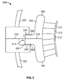
- FIG 3 is a schematic illustration of a portion of a nozzle carrier 300 that may be used with turbine 10 (shown in Figure 1).
- Nozzle carrier 300 includes an upper half 302 and a lower half 304.
- Upper half 302 includes a first radially outwardly extending flange 306 and lower half 304 includes a second radially outwardly extending flange 308.
- Each flange 306 and 308 are configured to mate along a mating joint 310.
- flange 306 is not used, for example, based on the weight of upper half 302.
- a plurality of nozzle airfoils 312 are configured to couple to nozzle carrier 300 in a circumferentially spaced arrangement.
- a pocket 314 is formed in the turbine casing or turbine shell structure 316 at a joint 318 between an upper shell 320 and a lower shell 322. Extending flanges 306 and 308 are configured to be received in pocket 314 such that lower half 304 is vertically supported by shell structure 316.
- pocket 314 includes a recess 324 configured to receive a shim 326, which is "trapped" in a fixed position in recess 324. Accordingly, shim 326 is removable from recess 324 without removing nozzle carrier 300 or the turbine rotor from shell structure 316. Rather, carrier 300 is only lifted slightly at the associated side to allow the "trapped" shim to release from pocket 314.
- shim 326 is fabricated as a "shim pack" in which small thicknesses of shim layers are removable to adjust the thickness of shim 326 such that machining of shim 326 is reduced or eliminated.
- a second shim is positioned opposite shim 326 between upper shell 320 and extending flange 306 to limit the lifting of casing 316 if the torque applied to carrier 300 is greater that the assembled weight of carrier 300 on the associated side.
- FIG 4 is a schematic side view of a portion of turbine engine 10 (shown in Figure 1).
- Turbine engine 10 includes an upper half casing 400 that is bolted to a lower half casing (not shown) when turbine engine 10 is fully assembled.
- a nozzle carrier 402 mates to radially inner surfaces of casing 400. Such mating facilitates maintaining nozzle carrier 402 in a relatively fixed position with respect to a rotatable member 404, such as a turbine rotor.
- Nozzle carrier 402 includes a radial projection 406 that is configured to mate with a complementary groove 408 in casing 400.
- a shim 410 is insertable between projection 406 and groove 408 to limit the vertical movement of the casing.
- shim 410 is a round shim that is slightly recessed in projection 406.
- a similar configuration in the lower half casing and lower nozzle carrier segment may also be used.
- FIG 5 is a schematic illustration of a portion of a nozzle carrier 500 that may be used with turbine 10 (shown in Figure 1).
- Figure 6 is a plan view of nozzle carrier 500 taken along lines A-A (shown in Figure 5).
- Figure 7 is a perspective view of a portion of nozzle carrier 500.
- a turbine casing 502 includes a pocket 504 configured to receive a radially outwardly radially extending flange 506 of a carrier support member 508.
- Carrier support member 508 includes a vertically extending body 509 coupled to flange 506 at a first end 510 and radially inwardly extending flange 512 coupled to a second opposing end 514.
- Flange 512 is configured to engage nozzle carrier 500 such that a weight of nozzle carrier 50 is transferred through carrier support member 508 to casing 502.
- inwardly extending flange 512 is received in a recess 516 formed in a radially outward periphery of nozzle carrier 500.
- Outwardly radially extending flange 506 includes a vertically oriented hole 520 configured to receive a selectably adjustable shim member, such as an adjustment screw 522.
- a selectably adjustable shim member such as an adjustment screw 522.
- threads 524 on adjustment screw 522 engage complementary threads 526 cut into hole 520.
- threads 524 on adjustment screw 522 engage a locking nut 528.
- Adjustment screw 522 is further configured to transfer the weight of carrier 500 to a wear pad 530. Adjustment screw 522 is utilized to adjust a position of carrier 500 with respect to casing 502.
- Wear pad 530 is fabricated from a sacrificial material and protects casing 502 and adjustment screw 522 from mutual wear during an adjustment procedure.
- a locking plate 532 is used to lock adjustment screw 522 into a fixed position when the adjustment procedure is completed.
- the above-described trapped shim carrier system is a cost-effective and highly reliable method for adjusting a vertical position of rotatable machine components without having to completely disassemble the machine.
Abstract
Description
- This invention generally relates to assembling rotatable machinery. More specifically, the invention is directed to alignment of components within a stationary casing.
- At least some known steam turbine designs include static nozzle segments that direct a flow of steam into rotating buckets coupled to a rotatable member. The nozzle airfoil construction is typically called a diaphragm stage. When more than one nozzle is supported by an outer structure or ring the construction is generally referred to as a nozzle carrier for a "drum construction" flowpath. The nozzle carrier is supported vertically by several methods at a horizontal joint between an upper carrier half and a lower carrier half. Typically the vertical supports include support bars, pins or flanges welded to the turbine casing. The flanges may also be cast as part of the turbine casing if using a cast construction for the nozzle carrier. Alignment of turbine components during assembly may take several shifts or days to adjust, as both the carrier and the rotor must be removed to make the adjustment.
- At least some known casings support the nozzle carrier using blocks under the carrier horizontal supports. The rotor and/or the nozzle carrier must be removed to make modification to the vertical position of the carrier. Typically the support blocks are bolted to the casing or carrier. The adjusting blocks have to be removed for machining (grinding) to achieve the proper casing vertical position relative to the turbine centerline. The blocks are then re-installed and the carrier and rotor replaced to check if proper alignment was achieved. The sequence is then repeated to verify the position and repeated if necessary. This process is both time consuming and costly.
- In one embodiment, a machine casing component carrier includes a support member configured to fixedly engage the machine component, an outwardly radially extending flange configured to engage a complementary receptacle formed in the turbine casing such that the weight of the carrier is supported at least partially by the receptacle, and a selectably adjustable shim member positionable within the receptacle configured to control an alignment of the longitudinal axis of the machine component with respect to the longitudinal axis of the rotatable member. The carrier is configured to support a machine component such that the longitudinal axis of the machine component is adjustable with respect to a longitudinal axis of a rotatable member of the machine are provided.
- In another embodiment, a method of assembling a rotatable machine includes coupling a plurality of nozzle airfoils to an arcuate carrier including a radially outwardly extending flange, supporting the carrier by the flange in the casing receptacle, and adjusting a vertical position of the carrier with respect to the casing longitudinal axis using a shim positioned between the flange and the receptacle.
- In yet another embodiment, turbine includes a casing including an upper half shell and a lower half shell configured to couple together along a mating joint, a component carrier configured to support a turbine component such that the longitudinal axis of the turbine component is in substantial alignment with a longitudinal axis of a rotatable member of the turbine, the carrier including, a support member configured to fixedly engage the turbine component, an outwardly radially extending flange configured to engage a complementary receptacle formed in the turbine casing such that the weight of the carrier is supported at least partially by the receptacle, and a selectably adjustable shim member positionable within the receptacle configured to control an alignment of the longitudinal axis of the turbine component with respect to the longitudinal axis of the rotatable member.
- Embodiments of the present invention will now be described, by way of example only, with reference to the accompanying drawings, in which:
- Figure 1 is a schematic illustration of an exemplary opposed-flow steam turbine;
- Figure 2 is a perspective view of a nozzle carrier assembly configured to retain a plurality of nozzles of a turbine;
- Figure 3 is a schematic illustration of a portion of a nozzle carrier that may be used with the turbine shown in Figure 1;
- Figure 4 is a schematic side view of a portion of the turbine engine shown in Figure 1;
- Figure 5 is a schematic illustration of a portion of a nozzle carrier that may be used with the turbine shown in Figure 1;
- Figure 6 is a plan view of the nozzle carrier shown in Figure 5; and
- Figure 7 is a perspective view of a portion of the nozzle carrier shown in Figure 5.
- Figure 1 is a schematic illustration of an exemplary opposed-
flow steam turbine 10.Turbine 10 includes first and second low pressure (LP)sections turbine section rotor shaft 16 extends throughsections LP section nozzle casing 22 is divided along a horizontal plane and axially into upper andlower half sections LP sections central section 28 ofshell 22 includes a lowpressure steam inlet 30. Within outer shell orcasing 22,LP sections journal bearings flow splitter 40 extends between first andsecond turbine sections - It should be noted that although Figure 1 illustrates a double flow low pressure turbine, as will be appreciated by one of ordinary skill in the art, the present invention is not limited to being used with low pressure turbines and can be used with any double flow turbine including, but not limited to intermediate pressure (IP) turbines or high pressure (HP) turbines. In addition, the present invention is not limited to being used with double flow turbines, but rather may be used with single flow steam turbines as well, for example.
- During operation, low
pressure steam inlet 30 receives low pressure/intermediate temperature steam 50 from a source, for example, an HP turbine or IP turbine through a cross-over pipe (not shown). Thesteam 50 is channeled throughinlet 30 whereinflow splitter 40 splits the steam flow into twoopposite flow paths steam 50 is routed throughLP sections rotor shaft 16. The steamexits LP sections - Figure 2 is a perspective view of a
nozzle carrier assembly 210 configured to retain a plurality ofnozzles 212 of a turbine, for example, a steam turbine.Carrier 210 includes upper andlower carrier halves horizontal joint face 216.Nozzles 212 are arranged in an annular array thereof at axially spaced locations alongcarrier 210. Each array ofnozzles 212 includes a plurality ofdiscrete nozzles 212 stacked one against the other. When a rotor (not shown) is positioned withinlower carrier half 215 andcarrier halves joint interface 216,nozzles 212, together with airfoils or buckets on the rotor, form multiple stages of a turbine. - Figure 3 is a schematic illustration of a portion of a
nozzle carrier 300 that may be used with turbine 10 (shown in Figure 1).Nozzle carrier 300 includes anupper half 302 and alower half 304.Upper half 302 includes a first radially outwardly extendingflange 306 andlower half 304 includes a second radially outwardly extendingflange 308. Eachflange mating joint 310. In various embodiments,flange 306 is not used, for example, based on the weight ofupper half 302. A plurality ofnozzle airfoils 312 are configured to couple tonozzle carrier 300 in a circumferentially spaced arrangement. Apocket 314 is formed in the turbine casing orturbine shell structure 316 at ajoint 318 between anupper shell 320 and alower shell 322. Extendingflanges pocket 314 such thatlower half 304 is vertically supported byshell structure 316. In the exemplary embodiment,pocket 314 includes arecess 324 configured to receive ashim 326, which is "trapped" in a fixed position inrecess 324. Accordingly,shim 326 is removable fromrecess 324 without removingnozzle carrier 300 or the turbine rotor fromshell structure 316. Rather,carrier 300 is only lifted slightly at the associated side to allow the "trapped" shim to release frompocket 314. In an alternative embodiment,shim 326 is fabricated as a "shim pack" in which small thicknesses of shim layers are removable to adjust the thickness ofshim 326 such that machining ofshim 326 is reduced or eliminated. A second shim is positionedopposite shim 326 betweenupper shell 320 and extendingflange 306 to limit the lifting ofcasing 316 if the torque applied tocarrier 300 is greater that the assembled weight ofcarrier 300 on the associated side. - Figure 4 is a schematic side view of a portion of turbine engine 10 (shown in Figure 1).
Turbine engine 10 includes an upper half casing 400 that is bolted to a lower half casing (not shown) whenturbine engine 10 is fully assembled. Anozzle carrier 402 mates to radially inner surfaces ofcasing 400. Such mating facilitates maintainingnozzle carrier 402 in a relatively fixed position with respect to arotatable member 404, such as a turbine rotor.Nozzle carrier 402 includes aradial projection 406 that is configured to mate with acomplementary groove 408 incasing 400. Ashim 410 is insertable betweenprojection 406 and groove 408 to limit the vertical movement of the casing. The aerodynamic forces on the nozzles causes a circumferential force on the carrier that could cause lifting off of the lower casing shelf on one side. In the exemplary embodiment,shim 410 is a round shim that is slightly recessed inprojection 406. A similar configuration in the lower half casing and lower nozzle carrier segment may also be used. - Figure 5 is a schematic illustration of a portion of a
nozzle carrier 500 that may be used with turbine 10 (shown in Figure 1). Figure 6 is a plan view ofnozzle carrier 500 taken along lines A-A (shown in Figure 5). Figure 7 is a perspective view of a portion ofnozzle carrier 500. In the exemplary embodiment, aturbine casing 502 includes apocket 504 configured to receive a radially outwardly radially extendingflange 506 of acarrier support member 508.Carrier support member 508 includes a vertically extendingbody 509 coupled toflange 506 at afirst end 510 and radially inwardly extendingflange 512 coupled to a secondopposing end 514.Flange 512 is configured to engagenozzle carrier 500 such that a weight ofnozzle carrier 50 is transferred throughcarrier support member 508 tocasing 502. In the exemplary embodiment, inwardly extendingflange 512 is received in arecess 516 formed in a radially outward periphery ofnozzle carrier 500. - Outwardly radially extending
flange 506 includes a vertically orientedhole 520 configured to receive a selectably adjustable shim member, such as anadjustment screw 522. In the exemplary embodiment,threads 524 onadjustment screw 522 engagecomplementary threads 526 cut intohole 520. In an alternative embodiment,threads 524 onadjustment screw 522 engage a lockingnut 528.Adjustment screw 522 is further configured to transfer the weight ofcarrier 500 to awear pad 530.Adjustment screw 522 is utilized to adjust a position ofcarrier 500 with respect tocasing 502.Wear pad 530 is fabricated from a sacrificial material and protects casing 502 andadjustment screw 522 from mutual wear during an adjustment procedure. A lockingplate 532 is used to lockadjustment screw 522 into a fixed position when the adjustment procedure is completed. - The above-described trapped shim carrier system is a cost-effective and highly reliable method for adjusting a vertical position of rotatable machine components without having to completely disassemble the machine.
- While the invention has been described in terms of various specific embodiments, those skilled in the art will recognize that the invention can be practiced with modification within the spirit and scope of the claims.
Claims (10)
- A machine component carrier assembly (210) configured to support a machine component such that the longitudinal axis of the machine component is adjustable with respect to a longitudinal axis of a rotatable member (404) of the machine, said assembly comprising:a support member configured to fixedly engage the machine component;an outwardly radially extending flange (506) configured to engage a complementary receptacle formed in said machine casing such that the weight of the carrier is supported at least partially by said receptacle; anda selectably adjustable shim member (326) positionable within said receptacle configured to control an alignment of the longitudinal axis of the machine component with respect to the longitudinal axis of the rotatable member.
- An assembly (210) in accordance with Claim 1 further comprising a radially outwardly extending projection (406) configured to engage a complementary casing groove (408), and a shim (410) positionable between said projection and said groove such that a vertical movement of said component carrier is substantially prevented.
- An assembly (210) in accordance with Claim 2 wherein a thickness of said shim (410) is selectable.
- An assembly (210) in accordance with Claim 1 wherein said selectably adjustable shim member (326) comprises an adjustment screw (522) coupled to said machine component through said support member, said adjustment screw configured to control an alignment of the machine component with respect to the casing (22).
- An assembly (210) in accordance with Claim 1 wherein said support member is configured to fixedly engage the machine component along an inner periphery of the support member.
- An assembly (210) in accordance with Claim 1 wherein said shim member (326) comprises a plurality of shims (410).
- An assembly (210) in accordance with Claim 1 wherein said turbine casing (22) comprises and upper half (320) and a lower half (322) and wherein said shim member comprises a first shim positioned between the flange (506) and the lower half and a second shim positioned between the flange and the upper half.
- An assembly (210) in accordance with Claim 1 wherein said circular support member comprises a plurality of arcuate segments, each segment comprising a outwardly radially extending flange (506) configured to couple to at least one of an adjacent segment and a casing receptacle.
- A turbine (10) comprising:a casing (22) comprising an upper half shell (320) and a lower half shell (322) configured to couple together along a mating joint (318);a component carrier configured to support a turbine component such that the longitudinal axis of the turbine component is in substantial alignment with a longitudinal axis of a rotatable member (404) of the turbine, said carrier comprising:a support member configured to fixedly engage the turbine component;an outwardly radially extending flange (506) configured to engage a complementary receptacle formed in said turbine casing such that the weight of the carrier is supported at least partially by said receptacle; anda selectably adjustable shim member (326) positionable within said receptacle configured to control an alignment of the longitudinal axis of the turbine component with respect to the longitudinal axis of the rotatable member.
- A turbine (10) in accordance with Claim 9 further comprising a radially outwardly extending projection configured to engage a complementary casing groove (408), and a shim (410) positionable between said projection and said groove such that a vertical movement of said component carrier is substantially prevented.
Applications Claiming Priority (1)
| Application Number | Priority Date | Filing Date | Title |
|---|---|---|---|
| US11/355,208 US7419355B2 (en) | 2006-02-15 | 2006-02-15 | Methods and apparatus for nozzle carrier with trapped shim adjustment |
Publications (2)
| Publication Number | Publication Date |
|---|---|
| EP1826365A2 true EP1826365A2 (en) | 2007-08-29 |
| EP1826365A3 EP1826365A3 (en) | 2013-12-04 |
Family
ID=38047895
Family Applications (1)
| Application Number | Title | Priority Date | Filing Date |
|---|---|---|---|
| EP07102229.7A Withdrawn EP1826365A3 (en) | 2006-02-15 | 2007-02-13 | Nozzle carrier with trapped shim adjustment |
Country Status (4)
| Country | Link |
|---|---|
| US (1) | US7419355B2 (en) |
| EP (1) | EP1826365A3 (en) |
| JP (1) | JP2007218259A (en) |
| MX (1) | MX2007002000A (en) |
Cited By (5)
| Publication number | Priority date | Publication date | Assignee | Title |
|---|---|---|---|---|
| FR2928682A1 (en) * | 2008-03-17 | 2009-09-18 | Gen Electric | CONFIGURATION AND METHOD FOR SUPPORTING INNER ENVELOPE OF TURBINE. |
| EP2392784A1 (en) * | 2010-06-04 | 2011-12-07 | Siemens Aktiengesellschaft | Steam turbine assembly and method of assembling a steam turbine |
| CN102900480A (en) * | 2011-07-27 | 2013-01-30 | 阿尔斯通技术有限公司 | Device for the mutual fixation of two gas turbine casing components |
| WO2015156692A1 (en) * | 2014-04-11 | 2015-10-15 | General Electric Company | Adjustable wedge-shaped shim for an exhaust frame assembly of a turbomachine |
| US9726045B2 (en) | 2011-01-19 | 2017-08-08 | Mitsubishi Hitachi Power Systems, Ltd. | Turbine external compartment, frame for turbine external compartment, and method of constructing frame for turbine external compartment |
Families Citing this family (23)
| Publication number | Priority date | Publication date | Assignee | Title |
|---|---|---|---|---|
| US7722314B2 (en) * | 2006-06-22 | 2010-05-25 | General Electric Company | Methods and systems for assembling a turbine |
| US7887291B2 (en) * | 2007-05-15 | 2011-02-15 | General Electric Company | Support bar with adjustable shim design for turbine diaphragms |
| GB0811501D0 (en) * | 2008-06-24 | 2008-07-30 | Rolls Royce Plc | A Method of forming a blade assembly |
| WO2010141747A2 (en) * | 2009-06-03 | 2010-12-09 | Todd Dana | System for steam treatment of textiles |
| US8337151B2 (en) * | 2009-06-30 | 2012-12-25 | General Electric Company | System and method for aligning turbine components |
| US8528181B2 (en) * | 2009-07-10 | 2013-09-10 | Alstom Technology Ltd | Alignment of machine components within casings |
| US20110255959A1 (en) * | 2010-04-15 | 2011-10-20 | General Electric Company | Turbine alignment control system and method |
| US8662830B2 (en) * | 2010-06-11 | 2014-03-04 | General Electric Company | Adjustable support apparatus for steam turbine nozzle assembly |
| US20120009058A1 (en) * | 2010-07-09 | 2012-01-12 | General Electric Company | Compressible supports for turbine engines |
| CH703430A1 (en) * | 2010-07-13 | 2012-01-13 | Alstom Technology Ltd | Method for adjusting the rotor position in a gas turbine or steam turbine. |
| US20120020775A1 (en) * | 2010-07-21 | 2012-01-26 | General Electric Company | Flow splitter assembly for steam turbomachine and method |
| JP5675411B2 (en) * | 2011-02-10 | 2015-02-25 | 三菱重工業株式会社 | Support structure for steam turning device |
| US8834113B2 (en) * | 2011-07-19 | 2014-09-16 | General Electric Company | Alignment member for steam turbine nozzle assembly |
| US8870529B2 (en) | 2011-08-12 | 2014-10-28 | General Electric Company | Methods and apparatus to facilitate turbine casing assembly |
| JP5665724B2 (en) * | 2011-12-12 | 2015-02-04 | 株式会社東芝 | Stator blade cascade, method of assembling stator blade cascade, and steam turbine |
| US9890648B2 (en) * | 2012-01-05 | 2018-02-13 | General Electric Company | Turbine rotor rim seal axial retention assembly |
| US9441498B2 (en) * | 2013-10-30 | 2016-09-13 | Siemens Energy, Inc. | Process and tool for aligning a seal housing assembly with a casing of a gas turbine engine |
| US10287903B2 (en) | 2016-04-06 | 2019-05-14 | General Electric Company | Steam turbine drum nozzle having alignment feature, related assembly, steam turbine and storage medium |
| EP3284919A1 (en) * | 2016-08-16 | 2018-02-21 | General Electric Technology GmbH | Axial flow turbine having a diaphragm split in two halves at a joint plane |
| US10378383B2 (en) * | 2017-01-26 | 2019-08-13 | General Electric Company | Alignment apparatus for coupling diaphragms of turbines |
| JP6694837B2 (en) * | 2017-02-27 | 2020-05-20 | 三菱日立パワーシステムズ株式会社 | Steam turbine |
| WO2022051100A1 (en) * | 2020-09-02 | 2022-03-10 | Siemens Energy Global GmbH & Co. KG | Tool for alignment of seal segments |
| CN114135348B (en) * | 2021-11-11 | 2024-01-19 | 河北国源电气股份有限公司 | Adjustable integrated type holding ring for steam turbine |
Citations (3)
| Publication number | Priority date | Publication date | Assignee | Title |
|---|---|---|---|---|
| US3937589A (en) * | 1973-05-23 | 1976-02-10 | Kraftwerkunion Ag | High pressure double flow turbine construction |
| JPS59170404A (en) * | 1983-03-16 | 1984-09-26 | Toshiba Corp | Geothermal steam turbine |
| US6325596B1 (en) * | 2000-07-21 | 2001-12-04 | General Electric Company | Turbine diaphragm support system |
Family Cites Families (14)
| Publication number | Priority date | Publication date | Assignee | Title |
|---|---|---|---|---|
| JPS4026641Y1 (en) * | 1964-04-13 | 1965-09-10 | ||
| US3836281A (en) * | 1973-03-02 | 1974-09-17 | Carrier Corp | Nozzle structure for steam turbines |
| DE2635980C2 (en) * | 1976-08-10 | 1977-12-15 | Kraftwerk Union AG, 4330 Mülheim | Arrangement for centering the inner casing of a steam turbine |
| US4296538A (en) * | 1978-05-24 | 1981-10-27 | Carrier Corporation | Method of providing a sealing assembly between a steam chest and turbine casing |
| US4219201A (en) * | 1978-05-24 | 1980-08-26 | Carrier Corporation | Sealing assembly |
| US4362464A (en) * | 1980-08-22 | 1982-12-07 | Westinghouse Electric Corp. | Turbine cylinder-seal system |
| US5024579A (en) * | 1990-07-18 | 1991-06-18 | Westinghouse Electric Corp. | Fully floating inlet flow guide for double-flow low pressure steam turbines |
| US5249920A (en) * | 1992-07-09 | 1993-10-05 | General Electric Company | Turbine nozzle seal arrangement |
| US5915697A (en) * | 1997-09-22 | 1999-06-29 | General Electric Company | Flexible cloth seal assembly |
| US6702549B2 (en) * | 2000-03-02 | 2004-03-09 | Siemens Aktiengesellschaft | Turbine installation |
| US6352405B1 (en) * | 2000-08-09 | 2002-03-05 | General Electric Company | Interchangeable turbine diaphragm halves and related support system |
| US6547522B2 (en) * | 2001-06-18 | 2003-04-15 | General Electric Company | Spring-backed abradable seal for turbomachinery |
| US6502823B1 (en) * | 2001-12-07 | 2003-01-07 | General Electric Company | Actuating seal carrier for a turbine and method of retrofitting |
| US6572115B1 (en) * | 2001-12-21 | 2003-06-03 | General Electric Company | Actuating seal for a rotary machine and method of retrofitting |
-
2006
- 2006-02-15 US US11/355,208 patent/US7419355B2/en not_active Expired - Fee Related
-
2007
- 2007-02-13 EP EP07102229.7A patent/EP1826365A3/en not_active Withdrawn
- 2007-02-15 JP JP2007034514A patent/JP2007218259A/en active Pending
- 2007-02-15 MX MX2007002000A patent/MX2007002000A/en active IP Right Grant
Patent Citations (3)
| Publication number | Priority date | Publication date | Assignee | Title |
|---|---|---|---|---|
| US3937589A (en) * | 1973-05-23 | 1976-02-10 | Kraftwerkunion Ag | High pressure double flow turbine construction |
| JPS59170404A (en) * | 1983-03-16 | 1984-09-26 | Toshiba Corp | Geothermal steam turbine |
| US6325596B1 (en) * | 2000-07-21 | 2001-12-04 | General Electric Company | Turbine diaphragm support system |
Cited By (8)
| Publication number | Priority date | Publication date | Assignee | Title |
|---|---|---|---|---|
| FR2928682A1 (en) * | 2008-03-17 | 2009-09-18 | Gen Electric | CONFIGURATION AND METHOD FOR SUPPORTING INNER ENVELOPE OF TURBINE. |
| EP2392784A1 (en) * | 2010-06-04 | 2011-12-07 | Siemens Aktiengesellschaft | Steam turbine assembly and method of assembling a steam turbine |
| WO2011151329A1 (en) * | 2010-06-04 | 2011-12-08 | Siemens Aktiengesellschaft | Steam turbine assembly and method of assembling a steam turbine |
| US9726045B2 (en) | 2011-01-19 | 2017-08-08 | Mitsubishi Hitachi Power Systems, Ltd. | Turbine external compartment, frame for turbine external compartment, and method of constructing frame for turbine external compartment |
| CN102900480A (en) * | 2011-07-27 | 2013-01-30 | 阿尔斯通技术有限公司 | Device for the mutual fixation of two gas turbine casing components |
| EP2551473A1 (en) * | 2011-07-27 | 2013-01-30 | Alstom Technology Ltd | Device for the mutual fixation of two gas turbine casing components |
| CN102900480B (en) * | 2011-07-27 | 2015-08-05 | 阿尔斯通技术有限公司 | For the device that two parts interfix |
| WO2015156692A1 (en) * | 2014-04-11 | 2015-10-15 | General Electric Company | Adjustable wedge-shaped shim for an exhaust frame assembly of a turbomachine |
Also Published As
| Publication number | Publication date |
|---|---|
| US7419355B2 (en) | 2008-09-02 |
| US20070189893A1 (en) | 2007-08-16 |
| EP1826365A3 (en) | 2013-12-04 |
| JP2007218259A (en) | 2007-08-30 |
| MX2007002000A (en) | 2008-11-18 |
Similar Documents
| Publication | Publication Date | Title |
|---|---|---|
| US7419355B2 (en) | Methods and apparatus for nozzle carrier with trapped shim adjustment | |
| US8128353B2 (en) | Method and apparatus for matching the thermal mass and stiffness of bolted split rings | |
| US5302086A (en) | Apparatus for retaining rotor blades | |
| EP2375007B1 (en) | Support bar for steam turbine nozzle assembly | |
| EP2851523A1 (en) | Mid turbine frame system for gas turbine engine | |
| US9127559B2 (en) | Diaphragm for turbomachines and method of manufacture | |
| US7654794B2 (en) | Methods and apparatus for assembling steam turbines | |
| EP2666969A1 (en) | Turbine diaphragm construction | |
| EP1783324A2 (en) | Apparatus for channeling steam flow to turbines | |
| JP2011137447A (en) | Fixture and method for mounting articulated turbine buckets | |
| WO2011018413A1 (en) | Turbine diaphragms | |
| EP1054137A2 (en) | Mounting an inner shell within an outer turbine casing | |
| US7780407B2 (en) | Rotary machines and methods of assembling | |
| US20160069207A1 (en) | Fan disk for a jet engine and jet engine | |
| US8562292B2 (en) | Steam turbine singlet interface for margin stage nozzles with pinned or bolted inner ring | |
| US20130216359A1 (en) | Compressor | |
| EP3123002B1 (en) | Stator vane support system within a gas turbine engine | |
| EP2576998B1 (en) | Steam turbine assembly and method of assembling a steam turbine | |
| EP3172410B1 (en) | Stator vane system usable within a gas turbine engine | |
| US9650918B2 (en) | Austenitic segment for steam turbine nozzle assembly, and related assembly | |
| KR20140071254A (en) | Turbomachine flow divider and related turbomachine |
Legal Events
| Date | Code | Title | Description |
|---|---|---|---|
| PUAI | Public reference made under article 153(3) epc to a published international application that has entered the european phase |
Free format text: ORIGINAL CODE: 0009012 |
|
| AK | Designated contracting states |
Kind code of ref document: A2 Designated state(s): AT BE BG CH CY CZ DE DK EE ES FI FR GB GR HU IE IS IT LI LT LU LV MC NL PL PT RO SE SI SK TR |
|
| AX | Request for extension of the european patent |
Extension state: AL BA HR MK YU |
|
| PUAL | Search report despatched |
Free format text: ORIGINAL CODE: 0009013 |
|
| AK | Designated contracting states |
Kind code of ref document: A3 Designated state(s): AT BE BG CH CY CZ DE DK EE ES FI FR GB GR HU IE IS IT LI LT LU LV MC NL PL PT RO SE SI SK TR |
|
| AX | Request for extension of the european patent |
Extension state: AL BA HR MK RS |
|
| RIC1 | Information provided on ipc code assigned before grant |
Ipc: F01D 25/24 20060101AFI20131030BHEP Ipc: F01D 25/28 20060101ALI20131030BHEP |
|
| AKY | No designation fees paid | ||
| REG | Reference to a national code |
Ref country code: DE Ref legal event code: R108 |
|
| REG | Reference to a national code |
Ref country code: DE Ref legal event code: R108 Effective date: 20140813 |
|
| STAA | Information on the status of an ep patent application or granted ep patent |
Free format text: STATUS: THE APPLICATION IS DEEMED TO BE WITHDRAWN |
|
| 18D | Application deemed to be withdrawn |
Effective date: 20140605 |