EP1825028B1 - Electrolysis cell electrolyte pumping system - Google Patents
Electrolysis cell electrolyte pumping system Download PDFInfo
- Publication number
- EP1825028B1 EP1825028B1 EP05803533A EP05803533A EP1825028B1 EP 1825028 B1 EP1825028 B1 EP 1825028B1 EP 05803533 A EP05803533 A EP 05803533A EP 05803533 A EP05803533 A EP 05803533A EP 1825028 B1 EP1825028 B1 EP 1825028B1
- Authority
- EP
- European Patent Office
- Prior art keywords
- electrolyte
- pressure
- electrolysis cell
- gas
- pumping
- Prior art date
- Legal status (The legal status is an assumption and is not a legal conclusion. Google has not performed a legal analysis and makes no representation as to the accuracy of the status listed.)
- Expired - Lifetime
Links
Images


Classifications
-
- C—CHEMISTRY; METALLURGY
- C25—ELECTROLYTIC OR ELECTROPHORETIC PROCESSES; APPARATUS THEREFOR
- C25B—ELECTROLYTIC OR ELECTROPHORETIC PROCESSES FOR THE PRODUCTION OF COMPOUNDS OR NON-METALS; APPARATUS THEREFOR
- C25B15/00—Operating or servicing cells
- C25B15/08—Supplying or removing reactants or electrolytes; Regeneration of electrolytes
-
- C—CHEMISTRY; METALLURGY
- C25—ELECTROLYTIC OR ELECTROPHORETIC PROCESSES; APPARATUS THEREFOR
- C25B—ELECTROLYTIC OR ELECTROPHORETIC PROCESSES FOR THE PRODUCTION OF COMPOUNDS OR NON-METALS; APPARATUS THEREFOR
- C25B1/00—Electrolytic production of inorganic compounds or non-metals
- C25B1/01—Products
- C25B1/02—Hydrogen or oxygen
- C25B1/04—Hydrogen or oxygen by electrolysis of water
-
- C—CHEMISTRY; METALLURGY
- C25—ELECTROLYTIC OR ELECTROPHORETIC PROCESSES; APPARATUS THEREFOR
- C25B—ELECTROLYTIC OR ELECTROPHORETIC PROCESSES FOR THE PRODUCTION OF COMPOUNDS OR NON-METALS; APPARATUS THEREFOR
- C25B11/00—Electrodes; Manufacture thereof not otherwise provided for
-
- C—CHEMISTRY; METALLURGY
- C25—ELECTROLYTIC OR ELECTROPHORETIC PROCESSES; APPARATUS THEREFOR
- C25B—ELECTROLYTIC OR ELECTROPHORETIC PROCESSES FOR THE PRODUCTION OF COMPOUNDS OR NON-METALS; APPARATUS THEREFOR
- C25B9/00—Cells or assemblies of cells; Constructional parts of cells; Assemblies of constructional parts, e.g. electrode-diaphragm assemblies; Process-related cell features
- C25B9/05—Pressure cells
-
- H—ELECTRICITY
- H01—ELECTRIC ELEMENTS
- H01M—PROCESSES OR MEANS, e.g. BATTERIES, FOR THE DIRECT CONVERSION OF CHEMICAL ENERGY INTO ELECTRICAL ENERGY
- H01M8/00—Fuel cells; Manufacture thereof
- H01M8/04—Auxiliary arrangements, e.g. for control of pressure or for circulation of fluids
- H01M8/04082—Arrangements for control of reactant parameters, e.g. pressure or concentration
- H01M8/04201—Reactant storage and supply, e.g. means for feeding, pipes
-
- H—ELECTRICITY
- H01—ELECTRIC ELEMENTS
- H01M—PROCESSES OR MEANS, e.g. BATTERIES, FOR THE DIRECT CONVERSION OF CHEMICAL ENERGY INTO ELECTRICAL ENERGY
- H01M8/00—Fuel cells; Manufacture thereof
- H01M8/10—Fuel cells with solid electrolytes
- H01M2008/1095—Fuel cells with polymeric electrolytes
-
- Y—GENERAL TAGGING OF NEW TECHNOLOGICAL DEVELOPMENTS; GENERAL TAGGING OF CROSS-SECTIONAL TECHNOLOGIES SPANNING OVER SEVERAL SECTIONS OF THE IPC; TECHNICAL SUBJECTS COVERED BY FORMER USPC CROSS-REFERENCE ART COLLECTIONS [XRACs] AND DIGESTS
- Y02—TECHNOLOGIES OR APPLICATIONS FOR MITIGATION OR ADAPTATION AGAINST CLIMATE CHANGE
- Y02E—REDUCTION OF GREENHOUSE GAS [GHG] EMISSIONS, RELATED TO ENERGY GENERATION, TRANSMISSION OR DISTRIBUTION
- Y02E60/00—Enabling technologies; Technologies with a potential or indirect contribution to GHG emissions mitigation
- Y02E60/30—Hydrogen technology
- Y02E60/36—Hydrogen production from non-carbon containing sources, e.g. by water electrolysis
Definitions
- the present invention relates to a system for pumping electrolyte through an electrolysis cell.
- Electrolysis cells use electrical energy to generate reaction gases by splitting a compound of an electrolyte. Due to the chemical reaction of electrolysis, the concentration of the electrolyte constantly increases. Electrolysis cells work properly within a limited range of electrolyte concentration. If the concentration is too low, the electrical resistance of the electrolyte becomes too high and the efficiency of the electrolysis cell goes down. Alternately, if the electrolyte concentration is too high, the electrolyte becomes very corrosive and the electrolysis cell might be irreversibly damaged. For an alkaline electrolysis cell, a typical concentration range may, for example, be from 15 to 30 % KOH.
- the energy efficiency of an electrolysis cell depends on its internal resistance.
- the distance between positive and negative electrode of the electrolysis cell is kept small in order to have a low ohmic resistance between the electrodes.
- a typical distance is 1 mm.
- the electrolyte volume inside the cell is 10 ccm.
- the electrolyte in some cells may be pumped from a reservoir through the cell in order to keep the cell's electrolyte concentration in the proper range.
- the size of the reservoir determines the operating time of the electrolysis system.
- the electrolyte flow that has to be pumped through the cell depends on the concentration of the electrolyte in the reservoir. For example, assuming that the highest accepted concentration is 30 %, one has to replace the electrolyte in the electrolysis cell 5 times per hour at a starting concentration of 15 % and 68 times per hour at a starting concentration of 29 %. This means that the electrolyte flow that has to be pumped through the cell is between 50 and 680 ccm per hour.
- the gas diffusion electrodes that are used in some electrolysis cells for generating the reaction gases work best with a small differential pressure between the reaction gases and the electrolyte, with the electrolyte pressure being lower than the gas pressure.
- the electrolyte pressure has to be quite constant all over the cell and the pressure drop caused by the flow resistance has to be small.
- typical operation pressures of electrolysis cells may be 0.5 to 3 bars and the electrolyte pressure may also have to be that high for proper cell operation.
- the electrolyte is pumped by conventional pumps such as, for example, rotary pumps, gear type pumps, piston pumps or membrane pumps.
- conventional pumps such as, for example, rotary pumps, gear type pumps, piston pumps or membrane pumps.
- these pumps may offer one or more limitations, including for example, problems with handling low flow rates and/or high pressure flows and problematic power consumption.
- JP 09 157878 An example of a system for producing hydrogen and oxygen by electrolysis of water and that includes a water pump is described in JP 09 157878 .
- a system for pumping electrolyte through an electrolysis cell for generating a gas characterized in that the system further includes:
- the present invention relates to a system for pumping electrolyte through an electrolysis cell by using the pressure of at least one of the reaction gases generated by the cell itself.
- the present invention may also relate to an electrolysis system that couples the pressures of the generated gases with the pressure of the electrolyte.
- a pumping system uses the pressure of reaction gas generated by the electrolysis cell to cause pumping of electrolyte through the cell.
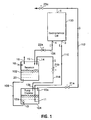
- a pumping system includes an electrolysis cell 100, an electrolyte reservoir 102 and an electrolyte pumping chamber 104.
- pumping chamber 104 may be positioned lower, as determined by gravity, than electrolyte reservoir 102.
- electrolysis cell The electrolysis cell, the electrolyte reservoir and the pumping chamber are connected by electrolyte conduits in a circuit so that an electrolyte flow circuit, arrows E, may be set up wherein electrolyte may flow through a conduit 106 from the cell to the reservoir, then through a conduit 108 from the reservoir to the pumping chamber and then through a conduit 110 back to the cell.
- the pumping chamber 104 may be connected to both the cell and the reservoir by reaction gas conduits 112, 114 respectively to permit pumping of electrolyte using the flow of generated gas, arrows G, as will be explained in greater detail below.
- the electrolysis cell has at least one outlet 1 for the reaction gases, an electrolyte inlet 3 and an electrolyte outlet 4.
- the reservoir may have an electrolyte inlet 15 that is connected through conduit 106 to the electrolyte outlet 4 of the electrolysis cell.
- the pumping chamber may have a gas inlet 10a that is connected via conduit 112 and a valve 21 a to the cell reaction gas outlet 1 and a gas outlet 10b that is connected via conduit 114 and another valve 21 b to a gas inlet 14 of the reservoir chamber.
- the pumping chamber may also have an electrolyte outlet 11 that is connected to the electrolyte inlet of the electrolysis cell 3 and an electrolyte inlet 13 that is connected to an electrolyte outlet 20 of the reservoir through the gas flow conduits.
- Valves 21a, 21b are coordinated, as, for example, by use of a switch, communication or control, such that only one of the valves can be open at any one time so that the pumping chamber is either in gas communication with the reservoir or in gas communication with the electrolysis cell 100.
- An electrolysis cell starts to generate gases generally as soon as a sufficient voltage is applied.
- a gas pressure is generated once cell 100 begins operation.
- valve 21 a when valve 21 a is open a portion of the generated reaction gas from cell 100 flows into the pumping chamber, where the pressure thereby also increases. Due to the increasing gas pressure, the electrolyte in the pumping chamber is also pressurized and driven out, and thus pumped out, of pumping chamber 104 to inlet 3, then through the electrolysis cell, out through outlet 4 and back to the reservoir through conduit 106 and the reservoir's electrolyte inlet 15.
- valves 21 a, 21 b are switched, so that valve 21 a is closed and valve 21b is opened, the connection between the electrolysis cell and the pumping chamber is interrupted and no further gas from the cell can reach the pumping chamber. Instead, with valve 21b open, the pumping chamber is now connected to the gas inlet 14 of the electrolyte reservoir through conduit 114 and renders pumping chamber 104 and electrolyte reservoir 102 pressure equilibrated. As such, electrolyte may flow from the reservoir to the pumping chamber through conduit 108 due to gravity.
- While the flow of electrolyte from reservoir 102 to pumping chamber 104 may be accomplished by gravity, other flows such as from the pumping chamber back to the cell may be positively driven by pumping drive generated from the use of reaction gas and, as such, need not require positioning to act ' on gravity.
- the reservoir being connected to the electrolysis cell by conduit 106 from outlet 4, may continue to fill with electrolyte that is passing, as for example by residual pumping pressure through the cell and/or by electrolyte that is draining along conduit 106.
- the electrolysis cell can remain in operation and can continue to generate gas.
- the valves are switched back, to open valve 21 a and close valve 21b, pumping chamber 104 may be substantially immediately pressurized again, the electrolyte flow from the reservoir to the pumping chamber stops and electrolyte is pumped to and through the electrolysis cell again. This cyclic operation can be used to pump electrolyte through the system.
- valves such as valve 13a at inlet 13 and or valve 11 a at pump chamber outlet 11 ( Figure 2 ), can be provided to control the direction of flow of gas or liquid, where desired or needed.
- Such valves can be check valves or positively driven valves as desired. Where valves 13a, 11 a, etc. are positively driven, their opening and closing may have to be coordinated with valves 21 a, 21 b in order to permit appropriate operation of the system.
- valves 21 a, 21 b As the system uses an alternating and coordinated opening and closing of valves 21 a, 21 b, it may be desirable to use a connected valve, such as a 3/2 way valve so that the opening of one valve automatically closes the other. Switching between valves 21 a, 21 b can be controlled by controllers such as, for example, level sensors, timers, etc. as desired. Such a system may also be useful for other valves in the system for which opening and closing needs to be coordinated.
- conduits between the components may be reduced by combining the conduits adjacent gas inlet 10a and the gas outlet 10b into one conduit, as gas flow will only be in one direction at one time, as controlled by valves 21 a, 21 b.
- cell 100 may operate under a pressure greater than ambient and optimal system operation may be dependent on maintaining the gas and electrolyte differential pressure. Thus, care may be taken for the balance of the absolute pressure of the system.
- the reservoir may be at ambient pressures, while the generated reaction gases and electrolyte in the cell may be at significantly higher pressures and it may be desirable to control pressure in the pumping system to avoid adverse differential pressures through the system.
- Pressure control may be achieved by use of pressure control devices 22a, 23a such as electrolyte flow resistors, controls, valves, etc. and/or reaction gas flow resistors, controls, valves, etc. Selection of these pressure control devices and positioning thereof may be used to couple directly the pressures of at least the pumping portion of the generated gases with the pressure of the electrolyte so that an operationally acceptable differential pressure is maintained in the cell.
- pressure control devices 22a, 23a such as electrolyte flow resistors, controls, valves, etc. and/or reaction gas flow resistors, controls, valves, etc. Selection of these pressure control devices and positioning thereof may be used to couple directly the pressures of at least the pumping portion of the generated gases with the pressure of the electrolyte so that an operationally acceptable differential pressure is maintained in the cell.
- an electrolyte/water refill inlet 18 may be provided in the system in either the pumping chamber or the reservoir, as desired.
- the refill inlet may be positioned to permit introduction of liquid to the system without shutting the system down.
- the refill may be positioned in the reservoir which operates open to atmosphere.
- an electrolysis cell electrolyte pumping system wherein the pressure of at least a portion of the gas generated by the electrolysis cell is used as driving force for the pumping of the electrolyte.
- the electrolyte pressure is coupled with the pressure of the pumping gas in such a way that the differential pressure between the electrolyte and the gas is as high as that differential pressure selected for the operation of the electrolysis cell.
- the pressures of both reaction gases may also be coupled in such a way that the differential pressure between the two gases is as high as that differential pressure selected for the operation of the electrolysis cell.
- the present pumping system for electrolysis cells can be realized in different ways as described in the following examples.
- the following examples show various components of the system and it should be appreciated that such components may be used alone or in combination, as desired, to provide an operational system with various selected attributes.
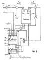
- Figure 2 shows one example electrolysis system that employs a first portion of the reaction gas from electrolysis cell 100 for pumping and provides a second portion of the reaction gas to a user through line 120 for an application other than pumping the electrolyte.
- the system actually generates two gasses with the first gas (gas 1) being used for pumping and the second gas (gas 2) passed for use/collection by the user.
- the system may be selected to generate oxygen as gas 1 and hydrogen as gas 2.
- formation of other reaction gasses may be of interest in an electrolysis system.
- gas 2 is emitted to the environment, as indicated at outlet 16.
- the electrolyte reservoir 102 is not pressurized in this example.
- the electrolyte pressure in the electrolysis cell be kept quite constant for optimal conditions of gas diffusion electrodes in the cell. Therefore, the electrolyte outlet 4 of the electrolysis cell isn't connected directly to the inlet 15 of the reservoir inlet, since if it were, the ambient pressure in the reservoir would be communicated to the outlet 4 which would generate an electrolyte pressure close to the pressure of gas 1 at the inlet 3 and close to ambient pressure at the outlet 4. In that case, the pressure drop between electrolyte inlet and outlet of the electrolysis cell would be close to the pressure of gas 1. Hence, an adjustable flow resistor 22 is used between the electrolysis cell and the reservoir.
- a primary pressure valve is shown but flow resistor 22 could also be embodied in different ways, for example, as through the use of a needle valve.
- the flow resistance has to be adjusted so that the electrolyte pressure at the outlet of the electrolysis cell is almost as high as at the inlet.
- the pressure of reaction gas 2 is also regulated by a primary pressure valve 23 and may have to be adjusted to the pressure of gas 1.
- a 3/2 way valve 21 is provided to control gas flow into and out of pumping chamber 104 through gas port 10.
- Valve 21 is switched by a liquid level switch 12.
- liquid level switch 12 Using liquid level switch 12, as soon as the electrolyte in the pumping chamber is sensed as being at a low level, valve 21 is switched to refill mode, which connects pumping chamber gas port 10 and reservoir gas inlet 14.
- switch 12 senses that the electrolyte level is at a high level, it signals valve 21 to switch to a pumping mode, wherein pumping chamber gas port 10 and gas outlet 1 of electrolysis cell are connected.
- the pressures of the two reaction gases and the electrolyte are not cooperatively coupled since the reservoir, and any gas 1 flowing therein, is open to atmosphere.
- the pressures of the reaction gases and the electrolyte are not directly coupled but are controlled individually and may have to be monitored in order to be adjusted on each other to maintain an operationally acceptable pressure differential in the cell. Monitoring can be for example by use of pressure sensors 5, 6.
- the system can include other operational components to facilitate operation such as, for example, one or more of strippers and filters 7, 8, 9 for removing entrained electrolyte from gas flows and returning it to electrolyte flow lines, a venting inlet 17, an electrolyte/water fill inlet 18, an electrolyte level switch 19, as may be useful for indicating when the system requires a water refill and a drain 27.
- strippers and filters 7, 8, 9 for removing entrained electrolyte from gas flows and returning it to electrolyte flow lines
- a venting inlet 17 for removing entrained electrolyte from gas flows and returning it to electrolyte flow lines
- an electrolyte/water fill inlet 18 an electrolyte level switch 19 as may be useful for indicating when the system requires a water refill and a drain 27.
- Figure 3 shows schematically a system that is similar to the one described ) in Example 1 but makes two reaction gases (gas 1 and gas 2) available to a user through lines 120a, 120b.
- the pressure of reaction gas 1 is also regulated by a primary pressure valve 24.
- the electrolyte in the reservoir is pressurized and a flow resistor, such as the flow resistor 22 of example 1 is not needed.
- the pressure difference used for the electrolyte pumping is generated while the pumping chamber is refilled from the reservoir.
- the pressure of the pumping gas (gas 1) and the electrolyte are directly coupled.
- the pressures of the two gases have to be monitored and adjusted on each other to control pressure differentials through the electrolysis cell.
- FIG 4 shows a system where the pressures of the two reaction gases are also coupled.
- a differential pressure valve 25 is used instead of the two primary pressure valves, indicated as 23, 24 in Figure 3 .
- the pressure of gas 1 has to be monitored and the pressure differences between gas 1 and gas 2 and between gas 1 and the electrolyte are fixed.
- the system shown in Figure 5 differs from the system of Example 3 in the way in which the 3/2 way valve 21 is switched.
- the triggering is done by a timer 28.
- the check valves 13a, 11 a at the electrolyte inlet 13 and outlet 11 of pumping chamber 104 are replaced by another 3/2 way valve 26 also triggered by timer 28.
- Valve 26 is capable of switching between a first connection between an electrolyte port 11 b of the pumping chamber and electrolysis cell electrolyte inlet 3 and a second connection between pumping chamber port 11 b and reservoir electrolyte outlet 20.
Landscapes
- Chemical & Material Sciences (AREA)
- Engineering & Computer Science (AREA)
- Electrochemistry (AREA)
- Chemical Kinetics & Catalysis (AREA)
- Materials Engineering (AREA)
- Metallurgy (AREA)
- Organic Chemistry (AREA)
- Inorganic Chemistry (AREA)
- Sustainable Energy (AREA)
- Sustainable Development (AREA)
- Manufacturing & Machinery (AREA)
- General Chemical & Material Sciences (AREA)
- Life Sciences & Earth Sciences (AREA)
- Electrolytic Production Of Non-Metals, Compounds, Apparatuses Therefor (AREA)
- Hybrid Cells (AREA)
Abstract
Description
- The present invention relates to a system for pumping electrolyte through an electrolysis cell.
- Electrolysis cells use electrical energy to generate reaction gases by splitting a compound of an electrolyte. Due to the chemical reaction of electrolysis, the concentration of the electrolyte constantly increases. Electrolysis cells work properly within a limited range of electrolyte concentration. If the concentration is too low, the electrical resistance of the electrolyte becomes too high and the efficiency of the electrolysis cell goes down. Alternately, if the electrolyte concentration is too high, the electrolyte becomes very corrosive and the electrolysis cell might be irreversibly damaged. For an alkaline electrolysis cell, a typical concentration range may, for example, be from 15 to 30 % KOH.
- The energy efficiency of an electrolysis cell depends on its internal resistance. Thus the distance between positive and negative electrode of the electrolysis cell is kept small in order to have a low ohmic resistance between the electrodes. In some electrolysis cells, a typical distance is 1 mm. In an electrolysis cell with an active area of 100 cm2 the electrolyte volume inside the cell is 10 ccm. At a current density of 200 mA/cm2 about 6 to 7 ccm of water are consumed by the electrolysis cell per hour. Therefore, the electrolyte in some cells may be pumped from a reservoir through the cell in order to keep the cell's electrolyte concentration in the proper range. The size of the reservoir determines the operating time of the electrolysis system. The electrolyte flow that has to be pumped through the cell depends on the concentration of the electrolyte in the reservoir. For example, assuming that the highest accepted concentration is 30 %, one has to replace the electrolyte in the
electrolysis cell 5 times per hour at a starting concentration of 15 % and 68 times per hour at a starting concentration of 29 %. This means that the electrolyte flow that has to be pumped through the cell is between 50 and 680 ccm per hour. - The gas diffusion electrodes that are used in some electrolysis cells for generating the reaction gases work best with a small differential pressure between the reaction gases and the electrolyte, with the electrolyte pressure being lower than the gas pressure. One has to take care about the differential pressure when pumping electrolyte through the cell. For the same reason the electrolyte pressure has to be quite constant all over the cell and the pressure drop caused by the flow resistance has to be small. For example, typical operation pressures of electrolysis cells may be 0.5 to 3 bars and the electrolyte pressure may also have to be that high for proper cell operation.
- Usually, the electrolyte is pumped by conventional pumps such as, for example, rotary pumps, gear type pumps, piston pumps or membrane pumps. However, in an efficient electrolysis system these pumps may offer one or more limitations, including for example, problems with handling low flow rates and/or high pressure flows and problematic power consumption.
- An example of a system for producing hydrogen and oxygen by electrolysis of water and that includes a water pump is described in
JP 09 157878 - In accordance with one aspect of the present invention, there is provided a system for pumping electrolyte through an electrolysis cell for generating a gas characterized in that the system further includes:
- an electrolyte reservoir connected via an inlet conduit to receive electrolyte from the electrolysis cell; and
- a pumping chamber connected via an outlet conduit to flow electrolyte to and through the electrolysis cell, the pumping chamber being in fluid connection with the electrolyte reservoir whereby it may be supplied with electrolyte, wherein
- at least a portion of the gas generated by the electrolysis cell is supplied to the pumping chamber and a pressure of the at least a portion of the gas is used as driving force for the pumping of electrolyte from the pumping chamber to and through the electrolysis cell.
- It is to be understood that other aspects of the present invention will become readily apparent to those skilled in the art from the following detailed description, wherein various embodiments of the invention are shown and described by way of illustration. As will be realized, the invention is capable for other and different embodiments and its several details are capable of modification in various other respects, all without departing from the spirit and scope of the present invention. Accordingly the drawings and detailed description are to be regarded as illustrative in nature and not as restrictive.
- Referring to the drawings wherein like reference numerals indicate similar parts throughout the several views, several aspects of the present invention are illustrated by way of example, and not by way of limitation, in detail in the figures, wherein:
-
Figure 1 is a schematic block diagram of an electrolysis cell and electrolyte pumping system according to one aspect of the present invention; -
Figure 2 is a schematic block diagram of an electrolysis cell and electrolyte pumping system according to another aspect of the present invention; -
Figure 3 is a schematic block diagram of an electrolysis cell and electrolyte pumping system according to another aspect of the present invention; -
Figure 4 is a schematic block diagram of an electrolysis cell and electrolyte pumping system according to another aspect of the present invention; and -
Figure 5 is a schematic block diagram of an electrolysis cell and electrolyte pumping system according to another aspect of the present invention. - The detailed description set forth below in connection with the appended drawings is intended as a description of various embodiments of the present invention. The detailed description includes specific details for the purpose of providing a comprehensive understanding of the present invention.
- The present invention relates to a system for pumping electrolyte through an electrolysis cell by using the pressure of at least one of the reaction gases generated by the cell itself. The present invention may also relate to an electrolysis system that couples the pressures of the generated gases with the pressure of the electrolyte.
- The present invention uses the pressure of reaction gas generated by the electrolysis cell to cause pumping of electrolyte through the cell. With reference to
Figure 1 , a pumping system according to the present invention includes anelectrolysis cell 100, anelectrolyte reservoir 102 and anelectrolyte pumping chamber 104. In operation,pumping chamber 104 may be positioned lower, as determined by gravity, thanelectrolyte reservoir 102. - The electrolysis cell, the electrolyte reservoir and the pumping chamber are connected by electrolyte conduits in a circuit so that an electrolyte flow circuit, arrows E, may be set up wherein electrolyte may flow through a
conduit 106 from the cell to the reservoir, then through aconduit 108 from the reservoir to the pumping chamber and then through aconduit 110 back to the cell. Also, thepumping chamber 104 may be connected to both the cell and the reservoir byreaction gas conduits - The electrolysis cell has at least one
outlet 1 for the reaction gases, anelectrolyte inlet 3 and anelectrolyte outlet 4. The reservoir may have anelectrolyte inlet 15 that is connected throughconduit 106 to theelectrolyte outlet 4 of the electrolysis cell. The pumping chamber may have agas inlet 10a that is connected viaconduit 112 and avalve 21 a to the cellreaction gas outlet 1 and agas outlet 10b that is connected viaconduit 114 and anothervalve 21 b to agas inlet 14 of the reservoir chamber. The pumping chamber may also have anelectrolyte outlet 11 that is connected to the electrolyte inlet of theelectrolysis cell 3 and anelectrolyte inlet 13 that is connected to anelectrolyte outlet 20 of the reservoir through the gas flow conduits. Valves 21a, 21b are coordinated, as, for example, by use of a switch, communication or control, such that only one of the valves can be open at any one time so that the pumping chamber is either in gas communication with the reservoir or in gas communication with theelectrolysis cell 100. - An electrolysis cell starts to generate gases generally as soon as a sufficient voltage is applied. In operation of a system according to
Figure 1 , for example, a gas pressure is generated oncecell 100 begins operation. In the described system, whenvalve 21 a is open a portion of the generated reaction gas fromcell 100 flows into the pumping chamber, where the pressure thereby also increases. Due to the increasing gas pressure, the electrolyte in the pumping chamber is also pressurized and driven out, and thus pumped out, ofpumping chamber 104 toinlet 3, then through the electrolysis cell, out throughoutlet 4 and back to the reservoir throughconduit 106 and the reservoir'selectrolyte inlet 15. If thevalves valve 21 a is closed andvalve 21b is opened, the connection between the electrolysis cell and the pumping chamber is interrupted and no further gas from the cell can reach the pumping chamber. Instead, withvalve 21b open, the pumping chamber is now connected to thegas inlet 14 of the electrolyte reservoir throughconduit 114 andrenders pumping chamber 104 andelectrolyte reservoir 102 pressure equilibrated. As such, electrolyte may flow from the reservoir to the pumping chamber throughconduit 108 due to gravity. - While the flow of electrolyte from
reservoir 102 to pumpingchamber 104 may be accomplished by gravity, other flows such as from the pumping chamber back to the cell may be positively driven by pumping drive generated from the use of reaction gas and, as such, need not require positioning to act ' on gravity. - The reservoir, being connected to the electrolysis cell by
conduit 106 fromoutlet 4, may continue to fill with electrolyte that is passing, as for example by residual pumping pressure through the cell and/or by electrolyte that is draining alongconduit 106. - While the reservoir fills the pumping chamber with electrolyte, the electrolysis cell can remain in operation and can continue to generate gas. When the valves are switched back, to open
valve 21 a andclose valve 21b, pumpingchamber 104 may be substantially immediately pressurized again, the electrolyte flow from the reservoir to the pumping chamber stops and electrolyte is pumped to and through the electrolysis cell again. This cyclic operation can be used to pump electrolyte through the system. - One or more valves, such as
valve 13a atinlet 13 and or valve 11 a at pump chamber outlet 11 (Figure 2 ), can be provided to control the direction of flow of gas or liquid, where desired or needed. Such valves can be check valves or positively driven valves as desired. Wherevalves 13a, 11 a, etc. are positively driven, their opening and closing may have to be coordinated withvalves - As the system uses an alternating and coordinated opening and closing of
valves valves - As may be appreciated, it may be possible to reduce the numbers of conduits between the components by combining the conduits
adjacent gas inlet 10a and thegas outlet 10b into one conduit, as gas flow will only be in one direction at one time, as controlled byvalves - It is usually desired to have the reaction gases available for use at a particular pressure for example 0.5 to 3 bar and in a closed electrolysis system it is desirable to maintain the electrolyte and reaction gases with a small differential pressure. In the illustrated embodiment,
cell 100 may operate under a pressure greater than ambient and optimal system operation may be dependent on maintaining the gas and electrolyte differential pressure. Thus, care may be taken for the balance of the absolute pressure of the system. In particular, it is noted that in some embodiments the reservoir may be at ambient pressures, while the generated reaction gases and electrolyte in the cell may be at significantly higher pressures and it may be desirable to control pressure in the pumping system to avoid adverse differential pressures through the system. Pressure control may be achieved by use ofpressure control devices - The illustrated system permits the water, which is consumed during electrolysis, to be replenished to adjust the electrolyte concentration without opening
cell 100. For example, an electrolyte/water refill inlet 18 may be provided in the system in either the pumping chamber or the reservoir, as desired. In some embodiments, the refill inlet may be positioned to permit introduction of liquid to the system without shutting the system down. In one embodiment, the refill may be positioned in the reservoir which operates open to atmosphere. - Thus, in view of the foregoing, an electrolysis cell electrolyte pumping system is provided wherein the pressure of at least a portion of the gas generated by the electrolysis cell is used as driving force for the pumping of the electrolyte. In one embodiment, the electrolyte pressure is coupled with the pressure of the pumping gas in such a way that the differential pressure between the electrolyte and the gas is as high as that differential pressure selected for the operation of the electrolysis cell. Where the cell generates two reaction gases separately, the pressures of both reaction gases may also be coupled in such a way that the differential pressure between the two gases is as high as that differential pressure selected for the operation of the electrolysis cell.
- The present pumping system for electrolysis cells can be realized in different ways as described in the following examples. The following examples show various components of the system and it should be appreciated that such components may be used alone or in combination, as desired, to provide an operational system with various selected attributes.
-
Figure 2 shows one example electrolysis system that employs a first portion of the reaction gas fromelectrolysis cell 100 for pumping and provides a second portion of the reaction gas to a user throughline 120 for an application other than pumping the electrolyte. In this particular embodiment, the system actually generates two gasses with the first gas (gas 1) being used for pumping and the second gas (gas 2) passed for use/collection by the user. In one embodiment, the system may be selected to generate oxygen asgas 1 and hydrogen asgas 2. However, formation of other reaction gasses may be of interest in an electrolysis system. - After use for pumping,
gas 2 is emitted to the environment, as indicated atoutlet 16. Thus, theelectrolyte reservoir 102 is not pressurized in this example. - In this embodiment, it is desirable that the electrolyte pressure in the electrolysis cell be kept quite constant for optimal conditions of gas diffusion electrodes in the cell. Therefore, the
electrolyte outlet 4 of the electrolysis cell isn't connected directly to theinlet 15 of the reservoir inlet, since if it were, the ambient pressure in the reservoir would be communicated to theoutlet 4 which would generate an electrolyte pressure close to the pressure ofgas 1 at theinlet 3 and close to ambient pressure at theoutlet 4. In that case, the pressure drop between electrolyte inlet and outlet of the electrolysis cell would be close to the pressure ofgas 1. Hence, anadjustable flow resistor 22 is used between the electrolysis cell and the reservoir. InFigure 2 , a primary pressure valve is shown but flowresistor 22 could also be embodied in different ways, for example, as through the use of a needle valve. The flow resistance has to be adjusted so that the electrolyte pressure at the outlet of the electrolysis cell is almost as high as at the inlet. The pressure ofreaction gas 2 is also regulated by aprimary pressure valve 23 and may have to be adjusted to the pressure ofgas 1. - A 3/2
way valve 21 is provided to control gas flow into and out of pumpingchamber 104 throughgas port 10.Valve 21 is switched by aliquid level switch 12. Usingliquid level switch 12, as soon as the electrolyte in the pumping chamber is sensed as being at a low level,valve 21 is switched to refill mode, which connects pumpingchamber gas port 10 andreservoir gas inlet 14. Whenswitch 12 senses that the electrolyte level is at a high level, it signalsvalve 21 to switch to a pumping mode, wherein pumpingchamber gas port 10 andgas outlet 1 of electrolysis cell are connected. - The pressures of the two reaction gases and the electrolyte are not cooperatively coupled since the reservoir, and any
gas 1 flowing therein, is open to atmosphere. Thus, the pressures of the reaction gases and the electrolyte are not directly coupled but are controlled individually and may have to be monitored in order to be adjusted on each other to maintain an operationally acceptable pressure differential in the cell. Monitoring can be for example by use ofpressure sensors - Of course, the system can include other operational components to facilitate operation such as, for example, one or more of strippers and
filters inlet 17, an electrolyte/water fill inlet 18, anelectrolyte level switch 19, as may be useful for indicating when the system requires a water refill and adrain 27. -
Figure 3 shows schematically a system that is similar to the one described ) in Example 1 but makes two reaction gases (gas 1 and gas 2) available to a user throughlines reaction gas 1 is also regulated by aprimary pressure valve 24. Thus, the electrolyte in the reservoir is pressurized and a flow resistor, such as theflow resistor 22 of example 1 is not needed. The pressure difference used for the electrolyte pumping is generated while the pumping chamber is refilled from the reservoir. - In this embodiment, the pressure of the pumping gas (gas 1) and the electrolyte are directly coupled. Thus, only the pressures of the two gases have to be monitored and adjusted on each other to control pressure differentials through the electrolysis cell.
-
Figure 4 shows a system where the pressures of the two reaction gases are also coupled. Thus, instead of the two primary pressure valves, indicated as 23, 24 inFigure 3 , adifferential pressure valve 25 is used. Thus only the pressure ofgas 1 has to be monitored and the pressure differences betweengas 1 andgas 2 and betweengas 1 and the electrolyte are fixed. - The system shown in
Figure 5 differs from the system of Example 3 in the way in which the 3/2way valve 21 is switched. In particular, instead of using a liquid level switch to triggervalve 21 the triggering is done by atimer 28. In addition, thecheck valves 13a, 11 a at theelectrolyte inlet 13 andoutlet 11 of pumpingchamber 104 are replaced by another 3/2way valve 26 also triggered bytimer 28.Valve 26 is capable of switching between a first connection between anelectrolyte port 11 b of the pumping chamber and electrolysiscell electrolyte inlet 3 and a second connection between pumpingchamber port 11 b andreservoir electrolyte outlet 20. - The previous description of the disclosed embodiments and examples is provided to enable any person skilled in the art to make or use the present invention. Various modifications to those embodiments will be readily apparent to those skilled in the art, and the generic principles defined herein may be applied to other embodiments without departing from the spirit or scope of the invention. Thus, the present invention is not intended to be limited to the embodiments shown herein, but is to be accorded the full scope consistent with the claims, wherein reference to an element in the singular, such as by use of the article "a" or "an" is not intended to mean "one and only one" unless specifically so stated, but rather "one or more". All structural and functional equivalents to the elements of the various embodiments described throughout the disclosure that are known or later come to be known to those of ordinary skill in the art are intended to be encompassed by the elements of the claims. Moreover, nothing disclosed herein is intended to be dedicated to the public regardless of whether such disclosure is explicitly recited in the claims. Specifically with respect to the United States, no claim element is to be construed under the provisions of 35
USC 112, sixth paragraph, unless the element is expressly recited using the phrase "means for" or "step for".
Claims (16)
- A system for pumping electrolyte through an electrolysis cell (100) for generating a gas characterized in that the system further includes:an electrolyte reservoir (102) connected via an inlet conduit (106) to receive electrolyte from the electrolysis cell (100); anda pumping chamber (104) connected via an outlet conduit (110) to flow electrolyte to and through the electrolysis cell (100), the pumping chamber (104) being in fluid connection with the electrolyte reservoir (102) whereby it may be supplied with electrolyte, whereinat least a portion of the gas generated by the electrolysis cell (100) is supplied to the pumping chamber (104) and a pressure of the at least a portion of the gas is used as driving force for the pumping of electrolyte from the pumping chamber (104) to and through the electrolysis cell (100).
- The system according to claim 1 further comprising a pressure valve (22a, 23a) wherein the electrolysis cell includes an electrolyte pressure and wherein the at least a portion of the gas generated includes a pumping gas pressure and wherein the electrolyte pressure is coupled via said valve (22a, 23a) with the pumping gas pressure in such a way that any differential pressure between the electrolyte and the at least a portion of the gas generated is as high as that differential pressure selected for operation of the electrolysis cell.
- The system according to claim 2 wherein the pressure valve (23a) is set to regulate the pumping gas pressure.
- The system according to claim 2 further comprising a differential pressure valve (25) wherein the at least a portion of the gas generated is a first gas and the electrolysis cell generates a second gas and wherein the differential pressure valve (25) regulates the pressures of both the first gas and the second gas so that the differential pressure between the two gases is as high as that differential pressure selected for the operation of the electrolysis cell.
- The system according to claim 1 wherein the at least a portion of the gas generated is pressure controlled to maintain an operational gas pressure within the electrolysis cell (100).
- The system according to claim 2 wherein the flow of electrolyte through the electrolysis cell (100) has an electrolyte pressure and is pressure controlled to maintain an operational electrolyte pressure within the electrolysis cell.
- The system according to claim 6 wherein the electrolyte pressure is pressure controlled using a flow resistor (22a) in the inlet conduit (106) between the electrolysis cell (100) and the electrolyte reservoir (102).
- The system according to claim 6 wherein the at least a portion of the gas generated has a gas pressure and is pressure controlled to maintain an operational gas pressure within the electrolysis cell (100) and the gas pressure of the at least a portion of the gas generated is monitored and adjusted against the electrolyte pressure to maintain an operational pressure differential within the electrolysis cell (100).
- The system according to claim 6 wherein the at least a portion of the gas generated has a gas pressure and the gas pressure is directly coupled to the electrolyte pressure using a flow resistor such that any differential pressure between the electrolyte and the at least a portion of the gas generated is as high as that differential pressure selected for operation of the electrolysis cell.
- The system according to claim 1 further comprising a pressure control (22) in the inlet conduit (106) and a pressure control in the outlet conduit (110) to pressure isolate the electrolyte of the electrolysis cell from the electrolyte reservoir (102) and from the pumping chamber (104).
- The system according to claim 1 wherein the electrolyte reservoir is pressure isolatable from the pumping chamber.
- The system according to claim 1 wherein the electrolysis cell (100) generates a second gas portion, which is passed to an application other than pumping the electrolyte.
- The system according to claim 1 wherein the electrolysis cell (100) operates at an elevated pressure greater than ambient and the system operates to pump electrolyte from the pumping chamber (104) while maintaining the elevated pressure in the electrolysis cell (100).
- The system according to claim 1 wherein the at least a portion of the gas generated is applied to an electrolyte pumping chamber (104) to elevate the pressure of the electrolyte therein and force it into the electrolysis cell (100).
- The system according to claim 13 wherein the electrolyte reservoir (102) passes the electrolyte to the electrolyte pumping chamber (104) when pressures are equalized between the electrolyte pumping chamber (104) and the electrolyte reservoir (102).
- The system according to claim 14 wherein the at least a portion of the gas generated has a gas pressure and the gas pressure is communicated to, and regulated to be substantially maintained in, the electrolyte pumping chamber (104) and the electrolyte reservoir (100) to maintain an operational pressure differential between the electrolyte and the at least a portion of the gas generated within the electrolysis cell.
Applications Claiming Priority (3)
| Application Number | Priority Date | Filing Date | Title |
|---|---|---|---|
| US52273704P | 2004-11-02 | 2004-11-02 | |
| US59486905P | 2005-05-13 | 2005-05-13 | |
| PCT/CA2005/001684 WO2006047876A1 (en) | 2004-11-02 | 2005-11-02 | Electrolysis cell electrolyte pumping system |
Publications (3)
| Publication Number | Publication Date |
|---|---|
| EP1825028A1 EP1825028A1 (en) | 2007-08-29 |
| EP1825028A4 EP1825028A4 (en) | 2009-01-07 |
| EP1825028B1 true EP1825028B1 (en) | 2011-06-15 |
Family
ID=36318853
Family Applications (1)
| Application Number | Title | Priority Date | Filing Date |
|---|---|---|---|
| EP05803533A Expired - Lifetime EP1825028B1 (en) | 2004-11-02 | 2005-11-02 | Electrolysis cell electrolyte pumping system |
Country Status (10)
| Country | Link |
|---|---|
| US (1) | US20080257740A1 (en) |
| EP (1) | EP1825028B1 (en) |
| JP (1) | JP2008519159A (en) |
| KR (1) | KR20080007540A (en) |
| AT (1) | ATE513068T1 (en) |
| AU (1) | AU2005301052B2 (en) |
| CA (1) | CA2586588A1 (en) |
| MX (1) | MX2007005230A (en) |
| NO (1) | NO20072809L (en) |
| WO (1) | WO2006047876A1 (en) |
Families Citing this family (9)
| Publication number | Priority date | Publication date | Assignee | Title |
|---|---|---|---|---|
| CA2534168A1 (en) * | 2006-01-27 | 2007-07-27 | Hy-Drive Technologies Ltd. | Hydrogen generating apparatus |
| CA2534604A1 (en) * | 2006-01-30 | 2007-07-30 | Hy-Drive Technologies Ltd. | Gas liquid separator for hydrogen generating apparatus |
| CA2534454A1 (en) * | 2006-01-30 | 2007-07-30 | Hy-Drive Technologies Ltd. | Hydrogen generating system for operation with engine turbo condition |
| US20100276296A1 (en) * | 2008-11-17 | 2010-11-04 | Etorus, Inc. | Electrolytic hydrogen generating system |
| US20130314093A1 (en) * | 2012-05-22 | 2013-11-28 | First Solar, Inc. | Method and system employing a solution contact for measurement |
| TWM555856U (en) * | 2016-08-10 | 2018-02-21 | Tanah Process Ltd | Hydrogen generator, and hydrogen gas inhaler including the same |
| JP6963789B2 (en) * | 2016-08-10 | 2021-11-10 | 有限会社ターナープロセス | Hydrogen gas generator and hydrogen gas inhalation device including it |
| KR102611826B1 (en) * | 2018-03-22 | 2023-12-11 | 가부시끼가이샤 도꾸야마 | Alkaline water electrolysis device and gas production method |
| DE102018208624A1 (en) * | 2018-05-30 | 2019-12-05 | Thyssenkrupp Uhde Chlorine Engineers Gmbh | Method and apparatus for providing at least one product stream by electrolysis and use |
Family Cites Families (11)
| Publication number | Priority date | Publication date | Assignee | Title |
|---|---|---|---|---|
| US5037518A (en) * | 1989-09-08 | 1991-08-06 | Packard Instrument Company | Apparatus and method for generating hydrogen and oxygen by electrolytic dissociation of water |
| US5316740A (en) * | 1992-03-26 | 1994-05-31 | Los Alamos Technical Associates, Inc. | Electrolytic cell for generating sterilization solutions having increased ozone content |
| US5268081A (en) * | 1992-08-04 | 1993-12-07 | Ceskoslovenska Akademie Ved | Electrolytic source of pressurized hydrogen |
| US5427658A (en) * | 1993-10-21 | 1995-06-27 | Electrosci Incorporated | Electrolytic cell and method for producing a mixed oxidant gas |
| JP3169050B2 (en) * | 1995-12-11 | 2001-05-21 | 神鋼パンテツク株式会社 | Hydrogen / oxygen generator and operating method thereof |
| WO2001045192A1 (en) * | 1999-12-16 | 2001-06-21 | Proton Energy Systems, Inc. | Low gravity electrochemical cell |
| CA2376830A1 (en) * | 2001-03-19 | 2002-09-19 | Opsco Energy Industries Ltd. | Energy exchange pressure-elevating liquid injection system |
| US7005075B2 (en) * | 2001-07-16 | 2006-02-28 | Miox Corporation | Gas drive electrolytic cell |
| US6793462B2 (en) * | 2002-07-25 | 2004-09-21 | Motorola, Inc. | Fluidic pump |
| AU2004224430C1 (en) * | 2003-02-21 | 2010-04-29 | Miox Corporation | Electrolytic cell for surface and point of use disinfection |
| US20050269211A1 (en) * | 2004-06-07 | 2005-12-08 | Zachar Oron D | Method of and apparatus for producing hydrogen using geothermal energy |
-
2005
- 2005-11-02 US US11/718,478 patent/US20080257740A1/en not_active Abandoned
- 2005-11-02 WO PCT/CA2005/001684 patent/WO2006047876A1/en not_active Ceased
- 2005-11-02 CA CA002586588A patent/CA2586588A1/en not_active Abandoned
- 2005-11-02 AT AT05803533T patent/ATE513068T1/en not_active IP Right Cessation
- 2005-11-02 MX MX2007005230A patent/MX2007005230A/en unknown
- 2005-11-02 KR KR1020077012410A patent/KR20080007540A/en not_active Withdrawn
- 2005-11-02 EP EP05803533A patent/EP1825028B1/en not_active Expired - Lifetime
- 2005-11-02 JP JP2007539436A patent/JP2008519159A/en active Pending
- 2005-11-02 AU AU2005301052A patent/AU2005301052B2/en not_active Ceased
-
2007
- 2007-06-01 NO NO20072809A patent/NO20072809L/en not_active Application Discontinuation
Also Published As
| Publication number | Publication date |
|---|---|
| KR20080007540A (en) | 2008-01-22 |
| AU2005301052A1 (en) | 2006-05-11 |
| ATE513068T1 (en) | 2011-07-15 |
| AU2005301052B2 (en) | 2010-12-16 |
| JP2008519159A (en) | 2008-06-05 |
| US20080257740A1 (en) | 2008-10-23 |
| MX2007005230A (en) | 2007-07-20 |
| WO2006047876A1 (en) | 2006-05-11 |
| NO20072809L (en) | 2007-07-31 |
| CA2586588A1 (en) | 2006-05-11 |
| EP1825028A1 (en) | 2007-08-29 |
| EP1825028A4 (en) | 2009-01-07 |
Similar Documents
| Publication | Publication Date | Title |
|---|---|---|
| AU2012312234B2 (en) | High pressure gas system | |
| KR100456198B1 (en) | Hydrogen fuel replenishment process and system | |
| AU2005301052B2 (en) | Electrolysis cell electrolyte pumping system | |
| WO2005028714A1 (en) | Apparatus and method for reducing instances of pump de-priming | |
| JP4778502B2 (en) | Gas-driven electrolytic cell | |
| KR102625513B1 (en) | Separate type bop applied water electrolysis device | |
| US8367261B2 (en) | Fuel cell device and method of operating the same | |
| US10305130B2 (en) | Tank-type power generation device capable of manufacturing high-pressure hydrogen and fuel cell vehicle | |
| KR20240090450A (en) | Pressurized water electrolysis device | |
| JP6600713B2 (en) | Gas generator | |
| CN101189364A (en) | Electrolytic cell electrolyte pumping system | |
| WO2018084117A1 (en) | Electrolyzed water server | |
| CN219342309U (en) | Electrochemical oxygen regulating device and refrigerator with same | |
| JP2000015259A (en) | Hypochlorous acid generator | |
| EP1605539A3 (en) | Fuel cell system and method of controlling thereof | |
| JP3667436B2 (en) | Electrolyzed water generator | |
| JP3169050B2 (en) | Hydrogen / oxygen generator and operating method thereof | |
| CN214936322U (en) | Wild-type hydrogen-rich adapter | |
| CN213983505U (en) | Steam generator without water tank | |
| JPH0742355U (en) | Oxygen gas Hydrogen gas supply device | |
| JPWO2016147434A1 (en) | Electrolyzed water generating device, electrode unit, and electrolyzed water generating method | |
| JP2018069189A (en) | Electrolyzed water server | |
| JP2006210177A (en) | Fuel cell system | |
| CN115893595A (en) | A control system for the concentration of electrolyzed water | |
| JPH04118455U (en) | Hydrogen/oxygen mixed gas generator |
Legal Events
| Date | Code | Title | Description |
|---|---|---|---|
| PUAI | Public reference made under article 153(3) epc to a published international application that has entered the european phase |
Free format text: ORIGINAL CODE: 0009012 |
|
| 17P | Request for examination filed |
Effective date: 20070517 |
|
| AK | Designated contracting states |
Kind code of ref document: A1 Designated state(s): AT BE BG CH CY CZ DE DK EE ES FI FR GB GR HU IE IS IT LI LT LU LV MC NL PL PT RO SE SI SK TR |
|
| AX | Request for extension of the european patent |
Extension state: AL BA HR MK YU |
|
| A4 | Supplementary search report drawn up and despatched |
Effective date: 20081204 |
|
| 17Q | First examination report despatched |
Effective date: 20090326 |
|
| GRAP | Despatch of communication of intention to grant a patent |
Free format text: ORIGINAL CODE: EPIDOSNIGR1 |
|
| RIN1 | Information on inventor provided before grant (corrected) |
Inventor name: SAUER, GERHARD Inventor name: HELMKE, JOACHIM |
|
| GRAS | Grant fee paid |
Free format text: ORIGINAL CODE: EPIDOSNIGR3 |
|
| GRAA | (expected) grant |
Free format text: ORIGINAL CODE: 0009210 |
|
| AK | Designated contracting states |
Kind code of ref document: B1 Designated state(s): AT BE BG CH CY CZ DE DK EE ES FI FR GB GR HU IE IS IT LI LT LU LV MC NL PL PT RO SE SI SK TR |
|
| AX | Request for extension of the european patent |
Extension state: AL BA HR MK YU |
|
| REG | Reference to a national code |
Ref country code: GB Ref legal event code: FG4D Ref country code: CH Ref legal event code: EP |
|
| REG | Reference to a national code |
Ref country code: IE Ref legal event code: FG4D |
|
| REG | Reference to a national code |
Ref country code: DE Ref legal event code: R096 Ref document number: 602005028573 Country of ref document: DE Effective date: 20110804 |
|
| REG | Reference to a national code |
Ref country code: NL Ref legal event code: VDEP Effective date: 20110615 |
|
| PG25 | Lapsed in a contracting state [announced via postgrant information from national office to epo] |
Ref country code: LT Free format text: LAPSE BECAUSE OF FAILURE TO SUBMIT A TRANSLATION OF THE DESCRIPTION OR TO PAY THE FEE WITHIN THE PRESCRIBED TIME-LIMIT Effective date: 20110615 Ref country code: SE Free format text: LAPSE BECAUSE OF FAILURE TO SUBMIT A TRANSLATION OF THE DESCRIPTION OR TO PAY THE FEE WITHIN THE PRESCRIBED TIME-LIMIT Effective date: 20110615 |
|
| PG25 | Lapsed in a contracting state [announced via postgrant information from national office to epo] |
Ref country code: CY Free format text: LAPSE BECAUSE OF FAILURE TO SUBMIT A TRANSLATION OF THE DESCRIPTION OR TO PAY THE FEE WITHIN THE PRESCRIBED TIME-LIMIT Effective date: 20110615 Ref country code: LV Free format text: LAPSE BECAUSE OF FAILURE TO SUBMIT A TRANSLATION OF THE DESCRIPTION OR TO PAY THE FEE WITHIN THE PRESCRIBED TIME-LIMIT Effective date: 20110615 Ref country code: AT Free format text: LAPSE BECAUSE OF FAILURE TO SUBMIT A TRANSLATION OF THE DESCRIPTION OR TO PAY THE FEE WITHIN THE PRESCRIBED TIME-LIMIT Effective date: 20110615 Ref country code: FI Free format text: LAPSE BECAUSE OF FAILURE TO SUBMIT A TRANSLATION OF THE DESCRIPTION OR TO PAY THE FEE WITHIN THE PRESCRIBED TIME-LIMIT Effective date: 20110615 Ref country code: SI Free format text: LAPSE BECAUSE OF FAILURE TO SUBMIT A TRANSLATION OF THE DESCRIPTION OR TO PAY THE FEE WITHIN THE PRESCRIBED TIME-LIMIT Effective date: 20110615 Ref country code: GR Free format text: LAPSE BECAUSE OF FAILURE TO SUBMIT A TRANSLATION OF THE DESCRIPTION OR TO PAY THE FEE WITHIN THE PRESCRIBED TIME-LIMIT Effective date: 20110916 |
|
| PG25 | Lapsed in a contracting state [announced via postgrant information from national office to epo] |
Ref country code: NL Free format text: LAPSE BECAUSE OF FAILURE TO SUBMIT A TRANSLATION OF THE DESCRIPTION OR TO PAY THE FEE WITHIN THE PRESCRIBED TIME-LIMIT Effective date: 20110615 Ref country code: BE Free format text: LAPSE BECAUSE OF FAILURE TO SUBMIT A TRANSLATION OF THE DESCRIPTION OR TO PAY THE FEE WITHIN THE PRESCRIBED TIME-LIMIT Effective date: 20110615 |
|
| PG25 | Lapsed in a contracting state [announced via postgrant information from national office to epo] |
Ref country code: EE Free format text: LAPSE BECAUSE OF FAILURE TO SUBMIT A TRANSLATION OF THE DESCRIPTION OR TO PAY THE FEE WITHIN THE PRESCRIBED TIME-LIMIT Effective date: 20110615 Ref country code: CZ Free format text: LAPSE BECAUSE OF FAILURE TO SUBMIT A TRANSLATION OF THE DESCRIPTION OR TO PAY THE FEE WITHIN THE PRESCRIBED TIME-LIMIT Effective date: 20110615 Ref country code: PT Free format text: LAPSE BECAUSE OF FAILURE TO SUBMIT A TRANSLATION OF THE DESCRIPTION OR TO PAY THE FEE WITHIN THE PRESCRIBED TIME-LIMIT Effective date: 20111017 Ref country code: IS Free format text: LAPSE BECAUSE OF FAILURE TO SUBMIT A TRANSLATION OF THE DESCRIPTION OR TO PAY THE FEE WITHIN THE PRESCRIBED TIME-LIMIT Effective date: 20111015 |
|
| PG25 | Lapsed in a contracting state [announced via postgrant information from national office to epo] |
Ref country code: SK Free format text: LAPSE BECAUSE OF FAILURE TO SUBMIT A TRANSLATION OF THE DESCRIPTION OR TO PAY THE FEE WITHIN THE PRESCRIBED TIME-LIMIT Effective date: 20110615 Ref country code: RO Free format text: LAPSE BECAUSE OF FAILURE TO SUBMIT A TRANSLATION OF THE DESCRIPTION OR TO PAY THE FEE WITHIN THE PRESCRIBED TIME-LIMIT Effective date: 20110615 Ref country code: PL Free format text: LAPSE BECAUSE OF FAILURE TO SUBMIT A TRANSLATION OF THE DESCRIPTION OR TO PAY THE FEE WITHIN THE PRESCRIBED TIME-LIMIT Effective date: 20110615 |
|
| PLBE | No opposition filed within time limit |
Free format text: ORIGINAL CODE: 0009261 |
|
| STAA | Information on the status of an ep patent application or granted ep patent |
Free format text: STATUS: NO OPPOSITION FILED WITHIN TIME LIMIT |
|
| 26N | No opposition filed |
Effective date: 20120316 |
|
| PG25 | Lapsed in a contracting state [announced via postgrant information from national office to epo] |
Ref country code: IT Free format text: LAPSE BECAUSE OF FAILURE TO SUBMIT A TRANSLATION OF THE DESCRIPTION OR TO PAY THE FEE WITHIN THE PRESCRIBED TIME-LIMIT Effective date: 20110615 |
|
| PG25 | Lapsed in a contracting state [announced via postgrant information from national office to epo] |
Ref country code: MC Free format text: LAPSE BECAUSE OF NON-PAYMENT OF DUE FEES Effective date: 20111130 Ref country code: DK Free format text: LAPSE BECAUSE OF FAILURE TO SUBMIT A TRANSLATION OF THE DESCRIPTION OR TO PAY THE FEE WITHIN THE PRESCRIBED TIME-LIMIT Effective date: 20110615 |
|
| REG | Reference to a national code |
Ref country code: CH Ref legal event code: PL |
|
| REG | Reference to a national code |
Ref country code: DE Ref legal event code: R097 Ref document number: 602005028573 Country of ref document: DE Effective date: 20120316 |
|
| GBPC | Gb: european patent ceased through non-payment of renewal fee |
Effective date: 20111102 |
|
| PG25 | Lapsed in a contracting state [announced via postgrant information from national office to epo] |
Ref country code: LI Free format text: LAPSE BECAUSE OF NON-PAYMENT OF DUE FEES Effective date: 20111130 Ref country code: CH Free format text: LAPSE BECAUSE OF NON-PAYMENT OF DUE FEES Effective date: 20111130 |
|
| REG | Reference to a national code |
Ref country code: FR Ref legal event code: ST Effective date: 20120731 |
|
| REG | Reference to a national code |
Ref country code: IE Ref legal event code: MM4A |
|
| REG | Reference to a national code |
Ref country code: DE Ref legal event code: R119 Ref document number: 602005028573 Country of ref document: DE Effective date: 20120601 |
|
| PG25 | Lapsed in a contracting state [announced via postgrant information from national office to epo] |
Ref country code: IE Free format text: LAPSE BECAUSE OF NON-PAYMENT OF DUE FEES Effective date: 20111102 Ref country code: GB Free format text: LAPSE BECAUSE OF NON-PAYMENT OF DUE FEES Effective date: 20111102 |
|
| PG25 | Lapsed in a contracting state [announced via postgrant information from national office to epo] |
Ref country code: FR Free format text: LAPSE BECAUSE OF NON-PAYMENT OF DUE FEES Effective date: 20111130 |
|
| PG25 | Lapsed in a contracting state [announced via postgrant information from national office to epo] |
Ref country code: ES Free format text: LAPSE BECAUSE OF FAILURE TO SUBMIT A TRANSLATION OF THE DESCRIPTION OR TO PAY THE FEE WITHIN THE PRESCRIBED TIME-LIMIT Effective date: 20110926 |
|
| PG25 | Lapsed in a contracting state [announced via postgrant information from national office to epo] |
Ref country code: LU Free format text: LAPSE BECAUSE OF NON-PAYMENT OF DUE FEES Effective date: 20111102 |
|
| PG25 | Lapsed in a contracting state [announced via postgrant information from national office to epo] |
Ref country code: BG Free format text: LAPSE BECAUSE OF FAILURE TO SUBMIT A TRANSLATION OF THE DESCRIPTION OR TO PAY THE FEE WITHIN THE PRESCRIBED TIME-LIMIT Effective date: 20110915 Ref country code: DE Free format text: LAPSE BECAUSE OF NON-PAYMENT OF DUE FEES Effective date: 20120601 |
|
| PG25 | Lapsed in a contracting state [announced via postgrant information from national office to epo] |
Ref country code: TR Free format text: LAPSE BECAUSE OF FAILURE TO SUBMIT A TRANSLATION OF THE DESCRIPTION OR TO PAY THE FEE WITHIN THE PRESCRIBED TIME-LIMIT Effective date: 20110615 |
|
| PG25 | Lapsed in a contracting state [announced via postgrant information from national office to epo] |
Ref country code: HU Free format text: LAPSE BECAUSE OF FAILURE TO SUBMIT A TRANSLATION OF THE DESCRIPTION OR TO PAY THE FEE WITHIN THE PRESCRIBED TIME-LIMIT Effective date: 20110615 |