EP1821393A2 - High power generator with enhanced stator heat removal - Google Patents
High power generator with enhanced stator heat removal Download PDFInfo
- Publication number
- EP1821393A2 EP1821393A2 EP07102744A EP07102744A EP1821393A2 EP 1821393 A2 EP1821393 A2 EP 1821393A2 EP 07102744 A EP07102744 A EP 07102744A EP 07102744 A EP07102744 A EP 07102744A EP 1821393 A2 EP1821393 A2 EP 1821393A2
- Authority
- EP
- European Patent Office
- Prior art keywords
- stator
- diameter
- generator
- rotor
- main
- Prior art date
- Legal status (The legal status is an assumption and is not a legal conclusion. Google has not performed a legal analysis and makes no representation as to the accuracy of the status listed.)
- Pending
Links
Images

Classifications
-
- H—ELECTRICITY
- H02—GENERATION; CONVERSION OR DISTRIBUTION OF ELECTRIC POWER
- H02K—DYNAMO-ELECTRIC MACHINES
- H02K9/00—Arrangements for cooling or ventilating
- H02K9/19—Arrangements for cooling or ventilating for machines with closed casing and closed-circuit cooling using a liquid cooling medium, e.g. oil
-
- H—ELECTRICITY
- H02—GENERATION; CONVERSION OR DISTRIBUTION OF ELECTRIC POWER
- H02K—DYNAMO-ELECTRIC MACHINES
- H02K1/00—Details of the magnetic circuit
- H02K1/06—Details of the magnetic circuit characterised by the shape, form or construction
- H02K1/12—Stationary parts of the magnetic circuit
- H02K1/20—Stationary parts of the magnetic circuit with channels or ducts for flow of cooling medium
-
- H—ELECTRICITY
- H02—GENERATION; CONVERSION OR DISTRIBUTION OF ELECTRIC POWER
- H02K—DYNAMO-ELECTRIC MACHINES
- H02K5/00—Casings; Enclosures; Supports
- H02K5/04—Casings or enclosures characterised by the shape, form or construction thereof
- H02K5/20—Casings or enclosures characterised by the shape, form or construction thereof with channels or ducts for flow of cooling medium
- H02K5/203—Casings or enclosures characterised by the shape, form or construction thereof with channels or ducts for flow of cooling medium specially adapted for liquids, e.g. cooling jackets
Definitions
- the present invention relates to relatively high power generators and, more particularly, to high power generators that are used with gas turbine engines such as those used in aircraft, tanks, ships, terrestrial vehicles, or other applications.
- AC generator systems to supply relatively constant frequency AC power.
- Many of the AC generator systems installed in these vehicles include three separate brushless generators, namely, a permanent magnet generator (PMG), an exciter, and a main generator.
- the PMG includes a rotor having permanent magnets mounted thereon, and a stator having a plurality of windings. When the PMG rotor rotates, the permanent magnets induce AC currents in PMG stator windings. These AC currents are typically fed to a regulator or a control device, which in turn outputs a DC current to the exciter.
- the exciter typically includes single-phase (e.g., DC) stator windings and multi-phase (e.g., three-phase) rotor windings.
- the DC current from the regulator or control device is supplied to exciter stator windings, and as the exciter rotor rotates, three phases of AC current are typically induced in the rotor windings.
- Rectifier circuits that rotate with the exciter rotor rectify this three-phase AC current, and the resulting DC currents are provided to the main generator.
- the main generator additionally includes a rotor and a stator having single-phase (e.g., DC) and multi-phase (e.g., three-phase) windings, respectively.
- the DC currents from the rectifier circuits are supplied to the rotor windings.
- three phases of AC current are induced in main generator stator windings.
- This three-phase AC current can then be provided to a load such as, for example, electrical aircraft systems.
- some of the electrical components within the generator may generate heat due to electrical losses, and may thus be supplied with a cooling medium.
- the main rotor windings and main stator windings are cooled using a cooling medium, such as a lubricant, that flows in and through the generator.
- the main rotor and main stator windings are cooled by spraying the cooling medium, via orifices in the main rotor shaft, onto end turns of the main rotor and main stator windings.
- the cooling medium flow through the main rotor shaft also provides conduction cooling of the main rotor along its axial length. Conduction cooling along the axial length of the main stator is provided via a stator back iron cooling flow path. More specifically, a portion of the cooling medium is directed through a flow path formed in or on the stator back iron.
- the cooling scheme can present certain drawbacks.
- the cooling scheme can result in insufficient cooling of the main stator near its axially positioned center, causing a relatively high temperature hot spot at or near this location, which can be detrimental to the stator windings.
- the present invention provides a high speed, high power generator that provides enhanced cooling of the main stator near its axially positioned center.
- a high power generator includes a generator housing, a main rotor, and a main stator.
- the generator housing has a main stator cooling flow passage formed therein that is configured to receive a flow of a cooling medium.
- the main rotor is rotationally mounted in the generator housing.
- the main stator is mounted within the generator housing and surrounds at least a portion of the main rotor.
- the main stator includes a stator core coupled to the generator housing adjacent the main stator cooling flow passage, and includes two or more nominal-diameter sections and one or more reduced-diameter sections.
- the nominal-diameter sections each have a first outer diameter
- the reduced-diameter sections each have a second outer diameter that is less than the first diameter.
- Each reduced-diameter section is disposed between two nominal-diameter sections and is in fluid communication with the stator cooling flow passage.
- a stator assembly for a high power generator includes a plurality of stator windings, and a stator core adapted to be coupled to a generator housing and having the plurality of stator windings wound thereon.
- the stator core includes two or more nominal-diameter sections and one or more reduced-diameter sections.
- the nominal-diameter sections each have a first outer diameter
- the reduced-diameter sections each have a second outer diameter that is less than the first diameter.
- Each reduced-diameter section is disposed between two nominal-diameter sections and is in fluid communication with the stator cooling flow passage.
- FIG. 1 is a functional schematic diagram of an exemplary high speed generator embodiment
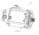
- FIG. 2 is a perspective view of a physical embodiment of the generator shown in FIG. 1;
- FIG. 3 is a simplified schematic cross section view of the exemplary generator shown in FIGS. 1 and 2 according to an embodiment of the present invention.
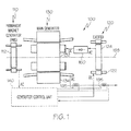
- FIG. 1 a functional schematic block diagram of an exemplary high speed generator system 100 for use with a gas turbine engine such as that in an aircraft is depicted.
- This exemplary generator system 100 which is commonly known as a brushless AC generator, includes a permanent magnet generator (PMG) 110, an exciter 120, a main generator 130, a generator control unit 140, and one or more rectifier assemblies 150.
- PMG permanent magnet generator
- a rotor 112 of the PMG 110, a rotor 124 of the exciter 120, and a rotor 132 of the main generator 130 all rotate.
- the rotational speed of these components may vary.
- the rotational speed may be, for example, in the range of about 12,000 to about 24,000 r.p.m., or greater.
- the PMG rotor 112 rotates, the PMG 110 generates and supplies, via a PMG stator 114, AC power to the generator control unit 140.
- the generator control unit 140 supplies direct current (DC) power to a stator 122 of the exciter 120.
- the exciter rotor 124 in turn supplies AC power to the rectifier assemblies 150.
- the output from the rectifier assemblies 150 is DC power and is supplied to the main rotor 132, which in turn outputs AC power from a main stator 134.
- the generator system 100 is capable of providing output power at a variety of frequencies and over a variety of frequency ranges. Further, typically the output power from the main generator stator 134 is three-phase AC power.
- the generator control unit 140 can regulate the power output based upon monitoring signals provided to it from monitoring devices 195.
- the PMG rotor 112, the exciter rotor 124, and the main rotor 132 are all mounted on a common shaft 136, and thus all rotate along a single axis 198 at the same rotational speed. It will be appreciated, however, that this is merely exemplary of a particular preferred embodiment. It will additionally be appreciated that the generator system 100, or at least portions of the system 100, may be housed within a generator housing 202, a perpsective view of which is illustrated in FIG. 2.
- FIG. 3 is a simplified cross section side view representative of the schematic and physical high power generators described above, it is seen that the shaft 136 includes an inner surface 302 that defines an internal fluid flow passage 304, and an outer surface 306.
- the shaft 136 receives a supply of cooling fluid such as, for example, oil or other lubricant, via an opening 308 in a first end 312 thereof.
- the supplied cooling fluid flows through the opening 308 and into and through the internal fluid flow passage 304 toward a closed second end 314 of the shaft 136.
- the shaft 136 additionally includes a plurality of end turn cooling supply orifices 316.
- the end turn cooling supply orifices each extend between the shaft inner 302 and outer 306 surfaces, and are thus in fluid communication with the internal fluid flow passage 304.
- the end turn cooling supply orifices 316 are disposed on the shaft 136 near both ends of the main rotor 132.
- the end turn cooling supply orifices 216 may be provided near only one end of the main rotor 132.
- the main rotor 132 is mounted on the shaft 136, and includes a plurality of poles 318, and a plurality of coils 322 (for clarity, only one shown).
- the poles 318 extend radially away from the shaft 136 and, as is generally known, are preferably spaced evenly apart from one another.
- the poles 318 are formed of a plurality of laminations 324, which are shrunk fit onto the shaft 136.
- the rotor laminations 324 as is generally known, are continuous stacks of a magnetically permeable material. The particular material may be any one of numerous magnetically permeable materials.
- the laminations 324 are formed of a magnetic alloy material such as, for example, vanadium permendur. It will be appreciated that this material is only exemplary, and that other suitable materials can be used for the main rotor laminations 324.
- each rotor coil 322 is wrapped, one each, around a pole 318, and are preferably formed by wrapping numerous individual wire windings around one of the poles 318.
- each rotor coil 322 includes two end turns 326 (e.g., 326-1, 326-2), each of which is made up of wire segments that loop around ends of the pole 318.
- cooling fluid supplied to the shaft inner fluid flow passage 304 is directed, via centrifugal force, through the end turn cooling supply orifices 316, and is sprayed onto, among other things, the rotor coil end turns 326.
- This cooling fluid spray provides cooling to the rotor coil end turns 326 and, as will be described further below, to portions of the main stator 134. It will be appreciated that the cooling fluid flowing through the shaft internal fluid flow passage 304 also provides conduction cooling for the main rotor laminations 324.
- the main stator 134 is also mounted within the generator housing 202, and is preferably positioned such that it surrounds the main rotor 132.
- the main stator 134 includes a stator core 328 and a plurality of stator coils 332, and is coupled to the generator housing 202. More specifically, the main stator 134 is preferably coupled to the generator housing 202 adjacent to a stator cooling flow passage 336 that is formed in the housing 202.
- the stator cooling flow passage 336 is configured to receive a flow of the cooling medium, which is used to conduction cool the main stator 134.
- the stator cooling flow passage 336 is implemented as a spirally configured cavity. It will be appreciated, however, that this is merely exemplary of any one of numerous configurations.
- the stator core 328 is configured such that one or more portions thereof have a reduced diameter.
- the stator core 328 at least in the depicted embodiment, includes two nominal-diameter sections 338 and one reduced-diameter section 342.
- the nominal-diameter sections 338 each have a first outer diameter (D1), and are coupled the generator housing 202.
- the reduced-diameter section 342 has a second outer diameter (D2) that is less than the first outer diameter, and is disposed between the nominal-diameter sections 338.
- the reduced-diameter section 342 forms a cavity 345 between the stator core 328 and the generator housing 202 that is in fluid communication with the stator cooling flow passage 336.
- stator cooling flow passage 336 when cooling medium is supplied to the stator cooling flow passage 336, the cooling medium additionally flows through the cavity 345, preferably in contact with the reduced-diameter section 342.
- the stator core 328 could be implemented with more than one reduced-diameter section 342.
- each is preferably disposed between two nominal-diameter sections 338.
- the main stator core 328 is preferably formed of a plurality of laminations 344.
- the main stator core laminations 344 are stacks of a magnetically permeable material, which may be any one of numerous magnetically permeable materials such as, for example, silicon iron, or vanadium permendur.
- the main stator core laminations 344 are not all substantially identical.
- main stator core nominal-diameter sections 338 are formed of a stack of nominal-diameter laminations, each having the nominal diameter
- main stator core reduced-diameter section(s) 342 are formed of a stack of reduced-diameter laminations, each having the reduced diameter.
- the stator coils 332 are wrapped around the stator core 328, preferably within non-illustrated slots formed in the stator core 328, and similar to the rotor coils 322 includes a pair of end turns 334 (e.g., 334-1, 334-2). A portion of the cooling fluid spray that is directed onto the rotor coil end turns 326 is also directed onto the stator coil end turns 334, and provides cooling thereto. It will be appreciated that the stator core 328 is additionally cooled via cooling fluid that flows through the stator cooling flow passage 336.
- the high speed, high power generator described herein provides enhanced cooling of the main stator, most notably near its axially positioned center. As such, the axial length of the generator can be increased, if needed to meet increase power generation demands, without adversely impacting thermal management of the generator.
Abstract
Description
- The present invention relates to relatively high power generators and, more particularly, to high power generators that are used with gas turbine engines such as those used in aircraft, tanks, ships, terrestrial vehicles, or other applications.
- Many vehicles, including aircraft, ships, and some terrestrial vehicles, include AC generator systems to supply relatively constant frequency AC power. Many of the AC generator systems installed in these vehicles include three separate brushless generators, namely, a permanent magnet generator (PMG), an exciter, and a main generator. The PMG includes a rotor having permanent magnets mounted thereon, and a stator having a plurality of windings. When the PMG rotor rotates, the permanent magnets induce AC currents in PMG stator windings. These AC currents are typically fed to a regulator or a control device, which in turn outputs a DC current to the exciter.
- The exciter typically includes single-phase (e.g., DC) stator windings and multi-phase (e.g., three-phase) rotor windings. The DC current from the regulator or control device is supplied to exciter stator windings, and as the exciter rotor rotates, three phases of AC current are typically induced in the rotor windings. Rectifier circuits that rotate with the exciter rotor rectify this three-phase AC current, and the resulting DC currents are provided to the main generator. The main generator additionally includes a rotor and a stator having single-phase (e.g., DC) and multi-phase (e.g., three-phase) windings, respectively. The DC currents from the rectifier circuits are supplied to the rotor windings. Thus, as the main generator rotor rotates, three phases of AC current are induced in main generator stator windings. This three-phase AC current can then be provided to a load such as, for example, electrical aircraft systems.
- In recent years, vehicles are being designed that rely more and more on electrical power. Thus, there is an ever-increasing demand for enhanced electrical generators, such as the one described above. One way of meeting these demands is through manipulation of the length and diameter ratio of a generator. For a given rotational speed, increasing the diameter of the generator increases the stress levels in the rotating components. Because some electrical generators rotate at relatively high speeds, with potential rotational speeds up to and in excess of 24,000 rpm, the stress levels in rotating components can, upon increasing the generator diameter, reach material limits. Thus, for many vehicles, the increased power demand can only be met by increasing the length of the generator.
- As is generally known, some of the electrical components within the generator may generate heat due to electrical losses, and may thus be supplied with a cooling medium. For example, in some generators the main rotor windings and main stator windings are cooled using a cooling medium, such as a lubricant, that flows in and through the generator. In particular, the main rotor and main stator windings are cooled by spraying the cooling medium, via orifices in the main rotor shaft, onto end turns of the main rotor and main stator windings. The cooling medium flow through the main rotor shaft also provides conduction cooling of the main rotor along its axial length. Conduction cooling along the axial length of the main stator is provided via a stator back iron cooling flow path. More specifically, a portion of the cooling medium is directed through a flow path formed in or on the stator back iron.
- Although the above described generator cooling configuration provides sufficient cooling for many generators, as the length of the generator is increased the cooling scheme can present certain drawbacks. In particular, the cooling scheme can result in insufficient cooling of the main stator near its axially positioned center, causing a relatively high temperature hot spot at or near this location, which can be detrimental to the stator windings.
- Hence, there is a need for a high speed, high power generator that addresses the above-noted drawback. Namely, a high speed, high power generator that supplies sufficient cooling to its main stator windings even if the length to diameter ratio is increased. The present invention addresses at least this need.
- The present invention provides a high speed, high power generator that provides enhanced cooling of the main stator near its axially positioned center.
- In one embodiment, and by way of example only, a high power generator includes a generator housing, a main rotor, and a main stator. The generator housing has a main stator cooling flow passage formed therein that is configured to receive a flow of a cooling medium. The main rotor is rotationally mounted in the generator housing. The main stator is mounted within the generator housing and surrounds at least a portion of the main rotor. The main stator includes a stator core coupled to the generator housing adjacent the main stator cooling flow passage, and includes two or more nominal-diameter sections and one or more reduced-diameter sections. The nominal-diameter sections each have a first outer diameter, and the reduced-diameter sections, each have a second outer diameter that is less than the first diameter. Each reduced-diameter section is disposed between two nominal-diameter sections and is in fluid communication with the stator cooling flow passage.
- In another exemplary embodiment, a stator assembly for a high power generator includes a plurality of stator windings, and a stator core adapted to be coupled to a generator housing and having the plurality of stator windings wound thereon. The stator core includes two or more nominal-diameter sections and one or more reduced-diameter sections. The nominal-diameter sections each have a first outer diameter, and the reduced-diameter sections, each have a second outer diameter that is less than the first diameter. Each reduced-diameter section is disposed between two nominal-diameter sections and is in fluid communication with the stator cooling flow passage.
- Other independent features and advantages of the preferred generator and stator assembly will become apparent from the following detailed description, taken in conjunction with the accompanying drawings which illustrate, by way of example, the principles of the invention.
- FIG. 1 is a functional schematic diagram of an exemplary high speed generator embodiment;
- FIG. 2 is a perspective view of a physical embodiment of the generator shown in FIG. 1; and
- FIG. 3 is a simplified schematic cross section view of the exemplary generator shown in FIGS. 1 and 2 according to an embodiment of the present invention.
- Before proceeding with the detailed description, it is to be appreciated that for convenience of explanation the present embodiment is depicted and described as being implemented in a brushless AC (alternating current) generator. However, the present invention is not limited to a brushless AC generator environment, but may be implemented in other AC generator designs needed in specific applications.
- Turning now to FIG. 1, a functional schematic block diagram of an exemplary high
speed generator system 100 for use with a gas turbine engine such as that in an aircraft is depicted. Thisexemplary generator system 100, which is commonly known as a brushless AC generator, includes a permanent magnet generator (PMG) 110, anexciter 120, amain generator 130, agenerator control unit 140, and one ormore rectifier assemblies 150. During operation, arotor 112 of thePMG 110, arotor 124 of theexciter 120, and arotor 132 of themain generator 130 all rotate. The rotational speed of these components may vary. In one embodiment, the rotational speed may be, for example, in the range of about 12,000 to about 24,000 r.p.m., or greater. As thePMG rotor 112 rotates, thePMG 110 generates and supplies, via a PMG stator 114, AC power to thegenerator control unit 140. Thegenerator control unit 140 supplies direct current (DC) power to astator 122 of theexciter 120. Theexciter rotor 124 in turn supplies AC power to therectifier assemblies 150. The output from therectifier assemblies 150 is DC power and is supplied to themain rotor 132, which in turn outputs AC power from amain stator 134. - The
generator system 100 is capable of providing output power at a variety of frequencies and over a variety of frequency ranges. Further, typically the output power from themain generator stator 134 is three-phase AC power. Thegenerator control unit 140 can regulate the power output based upon monitoring signals provided to it frommonitoring devices 195. In the depicted embodiment, thePMG rotor 112, theexciter rotor 124, and themain rotor 132 are all mounted on acommon shaft 136, and thus all rotate along asingle axis 198 at the same rotational speed. It will be appreciated, however, that this is merely exemplary of a particular preferred embodiment. It will additionally be appreciated that thegenerator system 100, or at least portions of thesystem 100, may be housed within agenerator housing 202, a perpsective view of which is illustrated in FIG. 2. - Turning now to FIG. 3, which is a simplified cross section side view representative of the schematic and physical high power generators described above, it is seen that the
shaft 136 includes aninner surface 302 that defines an internalfluid flow passage 304, and anouter surface 306. Theshaft 136 receives a supply of cooling fluid such as, for example, oil or other lubricant, via anopening 308 in afirst end 312 thereof. The supplied cooling fluid flows through theopening 308 and into and through the internalfluid flow passage 304 toward a closedsecond end 314 of theshaft 136. - As FIG. 3 also depicts, the
shaft 136 additionally includes a plurality of end turn coolingsupply orifices 316. The end turn cooling supply orifices each extend between the shaft inner 302 and outer 306 surfaces, and are thus in fluid communication with the internalfluid flow passage 304. In the depicted embodiment, the end turn coolingsupply orifices 316 are disposed on theshaft 136 near both ends of themain rotor 132. However, it will be appreciated that the end turn cooling supply orifices 216 may be provided near only one end of themain rotor 132. - The
main rotor 132, as was noted above, is mounted on theshaft 136, and includes a plurality ofpoles 318, and a plurality of coils 322 (for clarity, only one shown). Thepoles 318 extend radially away from theshaft 136 and, as is generally known, are preferably spaced evenly apart from one another. Thepoles 318 are formed of a plurality oflaminations 324, which are shrunk fit onto theshaft 136. The rotor laminations 324, as is generally known, are continuous stacks of a magnetically permeable material. The particular material may be any one of numerous magnetically permeable materials. In a particular preferred embodiment, thelaminations 324 are formed of a magnetic alloy material such as, for example, vanadium permendur. It will be appreciated that this material is only exemplary, and that other suitable materials can be used for themain rotor laminations 324. - The rotor coils 322 are wrapped, one each, around a
pole 318, and are preferably formed by wrapping numerous individual wire windings around one of thepoles 318. In the depicted embodiment, eachrotor coil 322 includes two end turns 326 (e.g., 326-1, 326-2), each of which is made up of wire segments that loop around ends of thepole 318. During generator operation cooling fluid supplied to the shaft innerfluid flow passage 304 is directed, via centrifugal force, through the end turn coolingsupply orifices 316, and is sprayed onto, among other things, the rotor coil end turns 326. This cooling fluid spray provides cooling to the rotor coil end turns 326 and, as will be described further below, to portions of themain stator 134. It will be appreciated that the cooling fluid flowing through the shaft internalfluid flow passage 304 also provides conduction cooling for themain rotor laminations 324. - The
main stator 134 is also mounted within thegenerator housing 202, and is preferably positioned such that it surrounds themain rotor 132. Themain stator 134 includes astator core 328 and a plurality of stator coils 332, and is coupled to thegenerator housing 202. More specifically, themain stator 134 is preferably coupled to thegenerator housing 202 adjacent to a statorcooling flow passage 336 that is formed in thehousing 202. The statorcooling flow passage 336 is configured to receive a flow of the cooling medium, which is used to conduction cool themain stator 134. In the depicted embodiment, the statorcooling flow passage 336 is implemented as a spirally configured cavity. It will be appreciated, however, that this is merely exemplary of any one of numerous configurations. - The
stator core 328 is configured such that one or more portions thereof have a reduced diameter. In this regard, thestator core 328, at least in the depicted embodiment, includes two nominal-diameter sections 338 and one reduced-diameter section 342. The nominal-diameter sections 338 each have a first outer diameter (D1), and are coupled thegenerator housing 202. The reduced-diameter section 342 has a second outer diameter (D2) that is less than the first outer diameter, and is disposed between the nominal-diameter sections 338. The reduced-diameter section 342 forms acavity 345 between thestator core 328 and thegenerator housing 202 that is in fluid communication with the statorcooling flow passage 336. As such, when cooling medium is supplied to the statorcooling flow passage 336, the cooling medium additionally flows through thecavity 345, preferably in contact with the reduced-diameter section 342. Thus, heat transfer from themain stator 134 is improved. Before proceeding further, it will be appreciated that thestator core 328 could be implemented with more than one reduced-diameter section 342. However, no matter the specific number of reduceddiameter sections 342 that are used, it will additionally be appreciated that each is preferably disposed between two nominal-diameter sections 338. - In addition to the above, it will be appreciated that the
main stator core 328, similar to themain rotor 132, is preferably formed of a plurality of laminations 344. The main stator core laminations 344, much like the mainrotor core laminations 324, are stacks of a magnetically permeable material, which may be any one of numerous magnetically permeable materials such as, for example, silicon iron, or vanadium permendur. However, as may be appreciated from the above paragraph, unlike the mainrotor core laminations 324, the main stator core laminations 344 are not all substantially identical. In particular, the main stator core nominal-diameter sections 338 are formed of a stack of nominal-diameter laminations, each having the nominal diameter, and the main stator core reduced-diameter section(s) 342 are formed of a stack of reduced-diameter laminations, each having the reduced diameter. - The stator coils 332 are wrapped around the
stator core 328, preferably within non-illustrated slots formed in thestator core 328, and similar to the rotor coils 322 includes a pair of end turns 334 (e.g., 334-1, 334-2). A portion of the cooling fluid spray that is directed onto the rotor coil end turns 326 is also directed onto the stator coil end turns 334, and provides cooling thereto. It will be appreciated that thestator core 328 is additionally cooled via cooling fluid that flows through the statorcooling flow passage 336. - The high speed, high power generator described herein provides enhanced cooling of the main stator, most notably near its axially positioned center. As such, the axial length of the generator can be increased, if needed to meet increase power generation demands, without adversely impacting thermal management of the generator.
- While the invention has been described with reference to a preferred embodiment, it will be understood by those skilled in the art that various changes may be made and equivalents may be substituted for elements thereof without departing from the scope of the invention. In addition, many modifications may be made to adapt to a particular situation or material to the teachings of the invention without departing from the essential scope thereof. Therefore, it is intended that the invention not be limited to the particular embodiment disclosed as the best mode contemplated for carrying out this invention, but that the invention will include all embodiments falling within the scope of the appended claims.
Claims (10)
- A high power generator (100), comprising:a generator housing (202) having a main stator cooling flow passage (336) formed therein, the main stator cooling flow passage (336) configured to receive a flow of a cooling medium;a main rotor (132) rotationally mounted in the generator housing (202); anda main stator (134) mounted within the generator housing (202) and surrounding at least a portion of the main rotor (132), the main stator (134) including a stator core (328) coupled to the generator housing (202) adjacent the main stator cooling flow passage (336), the stator core (328) including:two or more nominal-diameter sections (338), each having a first outer diameter (D1), andone or more reduced-diameter sections (342), each having a second outer diameter (D2) that is less than the first diameter (D1), each reduced-diameter section (342) (i) disposed between two nominal-diameter sections (338) and (ii) in fluid communication with the stator cooling flow passage (336).
- The generator (100) of Claim 1, wherein:the stator core nominal-diameter sections (338) each comprise a stack of nominal-diameter laminations, each nominal-diameter lamination having the first outer diameter (D1); andthe stator core reduced-diameter sections (342) each comprise a stack of reduced-diameter laminations, each reduced-diameter lamination having the second outer diameter (D2).
- The generator (100) of Claim 1, further comprising:a shaft (136) rotationally mounted within the generator housing (202) and on which the main rotor (132) is mounted, the shaft (136) including an inner surface (302) that defines an internal fluid flow passage (304), an outer surface (306), and a plurality of end turn cooling supply orifices (316) extending between the shaft inner (302) and outer surfaces (306), the internal fluid flow passage (304) configured to receive a flow of the cooling medium, and each end turn cooling supply orifice (316) in fluid communication with the internal fluid flow passage (304).
- The generator (100) of Claim 3, wherein:the main stator (134) further includes a plurality of main stator windings wound on the stator core (328), each stator winding having at least one end turn (334-1, 334-2); andthe end turn cooling supply orifices (316) are configured such that cooling medium supplied to the internal fluid flow passage (304) flows through at least selected ones of the end turn cooling supply orifices (316) and is directed toward the stator winding end turns (334-1, 334-2).
- The generator (100) of Claim 4, wherein the stator core (328) is configured such that the cooling medium in the stator cooling flow passage (336) does not contact any of the stator windings.
- The generator (100) of Claim 4, wherein:the main rotor (132) includes a plurality of rotor poles (318) that extend radially therefrom;the main rotor (132) further includes a plurality of rotor windings wound on the rotor poles (318), each of the rotor windings having at least one end turn (326-1, 326-2); andthe end turn cooling supply orifices (316) are configured such that cooling medium supplied to the internal fluid flow passage (304) flows through at least selected ones of the end turn cooling supply orifices (316) and is directed toward the rotor winding end turns (326-1, 326-2).
- The generator (100) of Claim 3, further comprising:an exciter rotor (124) mounted on the shaft (136); anda permanent magnet generator rotor (112) mounted the shaft (136).
- The generator (100) of Claim 7, further comprising:an exciter stator (134) mounted within the generator housing (202) and surrounding at least a portion of the exciter rotor (124); anda permanent magnet generator stator (114) mounted within the generator housing (202) and surrounding at least a portion of the permanent magnet generator rotor (112).
- A stator assembly, comprising:a plurality of stator windings;a stator core (328) adapted to be coupled to a generator housing (202), the stator core (328) having the plurality of stator windings wound thereon and including:two or more nominal-diameter sections (338), each having a first outer diameter (D 1), andone or more reduced-diameter sections (342), each having a second outer diameter (D2) that is less than the first diameter (D1), each reduced-diameter section (342) (i) disposed between two nominal-diameter sections (338) and (ii) in fluid communication with the stator cooling flow passage (336).
- The stator assembly of Claim 16, wherein:the stator core nominal-diameter sections (338) each comprise a stack of nominal-diameter laminations, each nominal-diameter lamination having the first outer diameter (D1);the stator core reduced-diameter sections (342) each comprise a stack of reduced-diameter laminations, each reduced-diameter lamination having the second outer diameter (D2).
Applications Claiming Priority (1)
| Application Number | Priority Date | Filing Date | Title |
|---|---|---|---|
| US11/359,116 US7439646B2 (en) | 2006-02-21 | 2006-02-21 | High power generator with enhanced stator heat removal |
Publications (2)
| Publication Number | Publication Date |
|---|---|
| EP1821393A2 true EP1821393A2 (en) | 2007-08-22 |
| EP1821393A3 EP1821393A3 (en) | 2009-01-21 |
Family
ID=37909429
Family Applications (1)
| Application Number | Title | Priority Date | Filing Date |
|---|---|---|---|
| EP07102744A Pending EP1821393A3 (en) | 2006-02-21 | 2007-02-20 | High power generator with enhanced stator heat removal |
Country Status (2)
| Country | Link |
|---|---|
| US (1) | US7439646B2 (en) |
| EP (1) | EP1821393A3 (en) |
Families Citing this family (7)
| Publication number | Priority date | Publication date | Assignee | Title |
|---|---|---|---|---|
| US8450888B2 (en) * | 2009-04-20 | 2013-05-28 | General Electric Company | Integrated brushless starter/generator system |
| US8143759B2 (en) * | 2009-04-30 | 2012-03-27 | Hamilton Sundstrand Corporation | Laminated stator assembly |
| DE112010004773T5 (en) * | 2010-03-24 | 2012-10-18 | Aisin Aw Co. Ltd. | Rotor for a rotating electrical machine |
| US20160294231A1 (en) | 2015-04-02 | 2016-10-06 | Hamilton Sundstrand Corporation | Stator heat transfer feature |
| US10560002B2 (en) * | 2017-03-29 | 2020-02-11 | Ford Global Technologies, Llc | Coolant flow distribution using coating materials |
| US11022004B2 (en) * | 2017-03-31 | 2021-06-01 | The Boeing Company | Engine shaft integrated motor |
| CN108471217A (en) * | 2018-07-06 | 2018-08-31 | 李天举 | Magnetomotive generator group |
Citations (4)
| Publication number | Priority date | Publication date | Assignee | Title |
|---|---|---|---|---|
| JPH08103053A (en) | 1994-09-30 | 1996-04-16 | Suzuki Motor Corp | Cooler of motor |
| JPH1141861A (en) | 1997-07-22 | 1999-02-12 | Denso Corp | Electric rotating machine |
| DE10019914A1 (en) | 1999-04-30 | 2001-02-01 | Valeo Equip Electr Moteur | Cooling configuration for a rotating electrical machine, includes a pocket of sheet material that forms an air circulation circuit through the rotating machine assembly |
| US20040066098A1 (en) | 2002-10-04 | 2004-04-08 | Doherty Kieran P.J. | High speed generator with the main rotor housed inside the shaft |
Family Cites Families (19)
| Publication number | Priority date | Publication date | Assignee | Title |
|---|---|---|---|---|
| US1578509A (en) | 1923-07-20 | 1926-03-30 | Westinghouse Electric & Mfg Co | Fluid-pressure control of turbo ventilation |
| US1594058A (en) | 1924-10-24 | 1926-07-27 | Gen Electric | Dynamo-electric machine |
| US1761587A (en) | 1928-11-19 | 1930-06-03 | Allis Chalmers Mfg Co | Dynamo-electric machine |
| US2285960A (en) | 1940-08-02 | 1942-06-09 | Carl J Fechheimer | Dynamoelectric machine |
| US3009072A (en) * | 1958-01-28 | 1961-11-14 | Scott L & Electromotors Ltd | Fluid cooled motors |
| US3805547A (en) | 1972-11-21 | 1974-04-23 | Trane Co | Refrigeration machine with liquid refrigerant cooled motor |
| FR2223859B1 (en) * | 1973-03-29 | 1976-06-25 | Siemens Ag | |
| US3963950A (en) | 1973-10-17 | 1976-06-15 | Hitachi, Ltd. | Stator of rotary electric machine |
| DE3134080A1 (en) * | 1981-08-28 | 1983-04-14 | Robert Bosch Gmbh, 7000 Stuttgart | ELECTRIC MACHINE, ESPECIALLY THREE-PHASE GENERATOR, WITH INTERNAL COOLING CHANNELS |
| US4514652A (en) | 1983-07-13 | 1985-04-30 | Sundstrand Corporation | Liquid cooled high speed synchronous machine |
| US5502368A (en) | 1994-06-06 | 1996-03-26 | Ecoair Corp. | Hybrid alternator with voltage regulator |
| US5682074A (en) * | 1994-03-02 | 1997-10-28 | Northrop Grumman Corporation | Electric vehicle motor |
| DE19645272A1 (en) * | 1996-11-02 | 1998-05-07 | Asea Brown Boveri | Gas-cooled electrical machine |
| US6091168A (en) * | 1998-12-22 | 2000-07-18 | Hamilton Sundstrand Corporation | Rotor for a dynamoelectric machine |
| JP2000308311A (en) * | 1999-04-14 | 2000-11-02 | Hitachi Ltd | Rotating electric machine |
| JP3806303B2 (en) | 2000-12-11 | 2006-08-09 | 三菱重工業株式会社 | Cooling structure in generator |
| GB2378046A (en) | 2001-07-18 | 2003-01-29 | Turbo Genset Company Ltd | Cooling flow in discoid stator windings |
| US6943469B2 (en) * | 2002-11-01 | 2005-09-13 | Siemens Westinghouse Power Corporation | Supplemented zonal ventilation system for electric generator |
| DE10344630A1 (en) * | 2003-09-25 | 2005-05-04 | Bosch Gmbh Robert | Fluid cooled electric machine and method of making such |
-
2006
- 2006-02-21 US US11/359,116 patent/US7439646B2/en not_active Expired - Fee Related
-
2007
- 2007-02-20 EP EP07102744A patent/EP1821393A3/en active Pending
Patent Citations (4)
| Publication number | Priority date | Publication date | Assignee | Title |
|---|---|---|---|---|
| JPH08103053A (en) | 1994-09-30 | 1996-04-16 | Suzuki Motor Corp | Cooler of motor |
| JPH1141861A (en) | 1997-07-22 | 1999-02-12 | Denso Corp | Electric rotating machine |
| DE10019914A1 (en) | 1999-04-30 | 2001-02-01 | Valeo Equip Electr Moteur | Cooling configuration for a rotating electrical machine, includes a pocket of sheet material that forms an air circulation circuit through the rotating machine assembly |
| US20040066098A1 (en) | 2002-10-04 | 2004-04-08 | Doherty Kieran P.J. | High speed generator with the main rotor housed inside the shaft |
Also Published As
| Publication number | Publication date |
|---|---|
| US20070194639A1 (en) | 2007-08-23 |
| US7439646B2 (en) | 2008-10-21 |
| EP1821393A3 (en) | 2009-01-21 |
Similar Documents
| Publication | Publication Date | Title |
|---|---|---|
| US7476994B2 (en) | High power generator with enhanced heat removal | |
| US7786630B2 (en) | Spray cooled V-wedge for aerospace generator | |
| US7342331B2 (en) | Multi-plane flexible rotor balancing | |
| US7439646B2 (en) | High power generator with enhanced stator heat removal | |
| US8922086B2 (en) | Electric machine having a hybrid-excited rotor | |
| CA2746242C (en) | Apparatus for a high speed sleeveless rotor | |
| KR960003205B1 (en) | Full flux reversal variable reluctance machine | |
| US7436098B2 (en) | Current limiting means for a generator | |
| US6097124A (en) | Hybrid permanent magnet/homopolar generator and motor | |
| EP1443189B1 (en) | Electric motor assisted turbocharger | |
| US20070236098A1 (en) | Vehicle alternator | |
| JP2007300787A (en) | Rotor for generator/motor | |
| US7015617B2 (en) | High speed generator with rotor coil support assemblies secured to interlamination disks | |
| US6984910B2 (en) | Generator with composite rotor coil retention components | |
| EP2814146A2 (en) | Permanent magnet synchronous machines with magnetic flux regulation | |
| EP1679427B1 (en) | Turbogenerator | |
| EP3410574B1 (en) | Hybrid synchronous machines | |
| AU749734B2 (en) | Electrical motor, especially a three-phase alternator | |
| JPH11164499A (en) | Ac generator for vehicle | |
| US20130221798A1 (en) | Alternator ratios | |
| US11705782B2 (en) | Electric motor cooling with oscillating heat pipes | |
| EP4024668A1 (en) | Rotor comprising wedges and winding head support with integrated wedge cooling distribution | |
| EP2615730B1 (en) | Brushless starter-generator assembly and method to control magnetic flux excitation | |
| EP4220907A1 (en) | Method and apparatus for cooling a rotor assembly | |
| JP2001086685A (en) | Rotor of electric rotating machine |
Legal Events
| Date | Code | Title | Description |
|---|---|---|---|
| PUAI | Public reference made under article 153(3) epc to a published international application that has entered the european phase |
Free format text: ORIGINAL CODE: 0009012 |
|
| AK | Designated contracting states |
Kind code of ref document: A2 Designated state(s): AT BE BG CH CY CZ DE DK EE ES FI FR GB GR HU IE IS IT LI LT LU LV MC NL PL PT RO SE SI SK TR |
|
| AX | Request for extension of the european patent |
Extension state: AL BA HR MK YU |
|
| PUAL | Search report despatched |
Free format text: ORIGINAL CODE: 0009013 |
|
| AK | Designated contracting states |
Kind code of ref document: A3 Designated state(s): AT BE BG CH CY CZ DE DK EE ES FI FR GB GR HU IE IS IT LI LT LU LV MC NL PL PT RO SE SI SK TR |
|
| AX | Request for extension of the european patent |
Extension state: AL BA HR MK RS |
|
| 17P | Request for examination filed |
Effective date: 20090710 |
|
| AKX | Designation fees paid |
Designated state(s): DE FR GB |
|
| 17Q | First examination report despatched |
Effective date: 20090908 |
|
| STAA | Information on the status of an ep patent application or granted ep patent |
Free format text: STATUS: EXAMINATION IS IN PROGRESS |