EP1821319A1 - Thermistor element, thermistor element production method and thermistor temperature sensor - Google Patents
Thermistor element, thermistor element production method and thermistor temperature sensor Download PDFInfo
- Publication number
- EP1821319A1 EP1821319A1 EP07000518A EP07000518A EP1821319A1 EP 1821319 A1 EP1821319 A1 EP 1821319A1 EP 07000518 A EP07000518 A EP 07000518A EP 07000518 A EP07000518 A EP 07000518A EP 1821319 A1 EP1821319 A1 EP 1821319A1
- Authority
- EP
- European Patent Office
- Prior art keywords
- thermistor
- reduction
- metal
- resistant coating
- phase
- Prior art date
- Legal status (The legal status is an assumption and is not a legal conclusion. Google has not performed a legal analysis and makes no representation as to the accuracy of the status listed.)
- Granted
Links
- 238000004519 manufacturing process Methods 0.000 title claims description 9
- 238000000576 coating method Methods 0.000 claims abstract description 98
- 239000011248 coating agent Substances 0.000 claims abstract description 96
- 239000000203 mixture Substances 0.000 claims abstract description 30
- 239000013078 crystal Substances 0.000 claims abstract description 8
- 229910052751 metal Inorganic materials 0.000 claims description 72
- 239000002184 metal Substances 0.000 claims description 57
- 239000000463 material Substances 0.000 claims description 42
- 229910044991 metal oxide Inorganic materials 0.000 claims description 32
- 150000004706 metal oxides Chemical class 0.000 claims description 29
- 239000002131 composite material Substances 0.000 claims description 23
- 238000005245 sintering Methods 0.000 claims description 19
- 229910003669 SrAl2O4 Inorganic materials 0.000 claims description 17
- 239000005084 Strontium aluminate Substances 0.000 claims description 17
- 239000002002 slurry Substances 0.000 claims description 13
- 238000000034 method Methods 0.000 claims description 2
- 230000000052 comparative effect Effects 0.000 description 30
- 239000000843 powder Substances 0.000 description 16
- PNEYBMLMFCGWSK-UHFFFAOYSA-N aluminium oxide Inorganic materials [O-2].[O-2].[O-2].[Al+3].[Al+3] PNEYBMLMFCGWSK-UHFFFAOYSA-N 0.000 description 11
- 238000009529 body temperature measurement Methods 0.000 description 11
- 229910052593 corundum Inorganic materials 0.000 description 11
- 229910001845 yogo sapphire Inorganic materials 0.000 description 11
- 238000013508 migration Methods 0.000 description 10
- 230000005012 migration Effects 0.000 description 10
- 238000012360 testing method Methods 0.000 description 9
- RUDFQVOCFDJEEF-UHFFFAOYSA-N yttrium(III) oxide Inorganic materials [O-2].[O-2].[O-2].[Y+3].[Y+3] RUDFQVOCFDJEEF-UHFFFAOYSA-N 0.000 description 9
- 229910052782 aluminium Inorganic materials 0.000 description 8
- 238000006243 chemical reaction Methods 0.000 description 8
- 229910019901 yttrium aluminum garnet Inorganic materials 0.000 description 8
- 239000011230 binding agent Substances 0.000 description 6
- 239000000470 constituent Substances 0.000 description 6
- QDOXWKRWXJOMAK-UHFFFAOYSA-N dichromium trioxide Chemical compound O=[Cr]O[Cr]=O QDOXWKRWXJOMAK-UHFFFAOYSA-N 0.000 description 6
- 238000001035 drying Methods 0.000 description 6
- 239000007789 gas Substances 0.000 description 6
- 230000015572 biosynthetic process Effects 0.000 description 5
- 238000005259 measurement Methods 0.000 description 5
- 238000002156 mixing Methods 0.000 description 5
- LFQSCWFLJHTTHZ-UHFFFAOYSA-N Ethanol Chemical compound CCO LFQSCWFLJHTTHZ-UHFFFAOYSA-N 0.000 description 4
- VYPSYNLAJGMNEJ-UHFFFAOYSA-N Silicium dioxide Chemical compound O=[Si]=O VYPSYNLAJGMNEJ-UHFFFAOYSA-N 0.000 description 4
- 230000007547 defect Effects 0.000 description 4
- NUJOXMJBOLGQSY-UHFFFAOYSA-N manganese dioxide Chemical compound O=[Mn]=O NUJOXMJBOLGQSY-UHFFFAOYSA-N 0.000 description 4
- 229910045601 alloy Inorganic materials 0.000 description 3
- 239000000956 alloy Substances 0.000 description 3
- 239000006227 byproduct Substances 0.000 description 3
- 239000011521 glass Substances 0.000 description 3
- 238000003780 insertion Methods 0.000 description 3
- 230000037431 insertion Effects 0.000 description 3
- 229920005989 resin Polymers 0.000 description 3
- 239000011347 resin Substances 0.000 description 3
- 239000002904 solvent Substances 0.000 description 3
- LEDMRZGFZIAGGB-UHFFFAOYSA-L strontium carbonate Chemical compound [Sr+2].[O-]C([O-])=O LEDMRZGFZIAGGB-UHFFFAOYSA-L 0.000 description 3
- 229910000018 strontium carbonate Inorganic materials 0.000 description 3
- 238000003466 welding Methods 0.000 description 3
- CSCPPACGZOOCGX-UHFFFAOYSA-N Acetone Chemical compound CC(C)=O CSCPPACGZOOCGX-UHFFFAOYSA-N 0.000 description 2
- ODINCKMPIJJUCX-UHFFFAOYSA-N Calcium oxide Chemical compound [Ca]=O ODINCKMPIJJUCX-UHFFFAOYSA-N 0.000 description 2
- 229910018967 Pt—Rh Inorganic materials 0.000 description 2
- QVGXLLKOCUKJST-UHFFFAOYSA-N atomic oxygen Chemical compound [O] QVGXLLKOCUKJST-UHFFFAOYSA-N 0.000 description 2
- 239000004568 cement Substances 0.000 description 2
- 229910052681 coesite Inorganic materials 0.000 description 2
- 150000001875 compounds Chemical class 0.000 description 2
- 229910052906 cristobalite Inorganic materials 0.000 description 2
- 238000010292 electrical insulation Methods 0.000 description 2
- 238000010438 heat treatment Methods 0.000 description 2
- 230000003647 oxidation Effects 0.000 description 2
- 238000007254 oxidation reaction Methods 0.000 description 2
- 229910052760 oxygen Inorganic materials 0.000 description 2
- 239000001301 oxygen Substances 0.000 description 2
- 125000004430 oxygen atom Chemical group O* 0.000 description 2
- 229920002037 poly(vinyl butyral) polymer Polymers 0.000 description 2
- 239000000377 silicon dioxide Substances 0.000 description 2
- 229910052682 stishovite Inorganic materials 0.000 description 2
- 229910052905 tridymite Inorganic materials 0.000 description 2
- 238000001238 wet grinding Methods 0.000 description 2
- HMUNWXXNJPVALC-UHFFFAOYSA-N 1-[4-[2-(2,3-dihydro-1H-inden-2-ylamino)pyrimidin-5-yl]piperazin-1-yl]-2-(2,4,6,7-tetrahydrotriazolo[4,5-c]pyridin-5-yl)ethanone Chemical compound C1C(CC2=CC=CC=C12)NC1=NC=C(C=N1)N1CCN(CC1)C(CN1CC2=C(CC1)NN=N2)=O HMUNWXXNJPVALC-UHFFFAOYSA-N 0.000 description 1
- BVKZGUZCCUSVTD-UHFFFAOYSA-L Carbonate Chemical compound [O-]C([O-])=O BVKZGUZCCUSVTD-UHFFFAOYSA-L 0.000 description 1
- 239000001856 Ethyl cellulose Substances 0.000 description 1
- ZZSNKZQZMQGXPY-UHFFFAOYSA-N Ethyl cellulose Chemical compound CCOCC1OC(OC)C(OCC)C(OCC)C1OC1C(O)C(O)C(OC)C(CO)O1 ZZSNKZQZMQGXPY-UHFFFAOYSA-N 0.000 description 1
- UFHFLCQGNIYNRP-UHFFFAOYSA-N Hydrogen Chemical compound [H][H] UFHFLCQGNIYNRP-UHFFFAOYSA-N 0.000 description 1
- AMQJEAYHLZJPGS-UHFFFAOYSA-N N-Pentanol Chemical compound CCCCCO AMQJEAYHLZJPGS-UHFFFAOYSA-N 0.000 description 1
- 239000004372 Polyvinyl alcohol Substances 0.000 description 1
- 229920005822 acrylic binder Polymers 0.000 description 1
- 238000004458 analytical method Methods 0.000 description 1
- 238000004364 calculation method Methods 0.000 description 1
- 229910052799 carbon Inorganic materials 0.000 description 1
- 150000004649 carbonic acid derivatives Chemical class 0.000 description 1
- 239000003054 catalyst Substances 0.000 description 1
- 229910052801 chlorine Inorganic materials 0.000 description 1
- 238000002485 combustion reaction Methods 0.000 description 1
- 238000009833 condensation Methods 0.000 description 1
- 230000005494 condensation Effects 0.000 description 1
- 229910003460 diamond Inorganic materials 0.000 description 1
- 239000010432 diamond Substances 0.000 description 1
- 229920001249 ethyl cellulose Polymers 0.000 description 1
- 235000019325 ethyl cellulose Nutrition 0.000 description 1
- 238000011156 evaluation Methods 0.000 description 1
- 230000002349 favourable effect Effects 0.000 description 1
- 229910052733 gallium Inorganic materials 0.000 description 1
- 150000004679 hydroxides Chemical class 0.000 description 1
- 238000010191 image analysis Methods 0.000 description 1
- JEIPFZHSYJVQDO-UHFFFAOYSA-N iron(III) oxide Inorganic materials O=[Fe]O[Fe]=O JEIPFZHSYJVQDO-UHFFFAOYSA-N 0.000 description 1
- 238000004898 kneading Methods 0.000 description 1
- WABPQHHGFIMREM-UHFFFAOYSA-N lead(0) Chemical compound [Pb] WABPQHHGFIMREM-UHFFFAOYSA-N 0.000 description 1
- -1 metal oxide compounds Chemical class 0.000 description 1
- 238000012986 modification Methods 0.000 description 1
- 230000004048 modification Effects 0.000 description 1
- 239000004570 mortar (masonry) Substances 0.000 description 1
- PLDDOISOJJCEMH-UHFFFAOYSA-N neodymium oxide Inorganic materials [O-2].[O-2].[O-2].[Nd+3].[Nd+3] PLDDOISOJJCEMH-UHFFFAOYSA-N 0.000 description 1
- 150000002823 nitrates Chemical class 0.000 description 1
- 229920002451 polyvinyl alcohol Polymers 0.000 description 1
- 239000011148 porous material Substances 0.000 description 1
- 229910052700 potassium Inorganic materials 0.000 description 1
- 238000002360 preparation method Methods 0.000 description 1
- 239000002994 raw material Substances 0.000 description 1
- 229910052710 silicon Inorganic materials 0.000 description 1
- 229910052708 sodium Inorganic materials 0.000 description 1
- 239000004071 soot Substances 0.000 description 1
- IATRAKWUXMZMIY-UHFFFAOYSA-N strontium oxide Inorganic materials [O-2].[Sr+2] IATRAKWUXMZMIY-UHFFFAOYSA-N 0.000 description 1
- 239000000126 substance Substances 0.000 description 1
- 238000006467 substitution reaction Methods 0.000 description 1
- 229910052717 sulfur Inorganic materials 0.000 description 1
- XLYOFNOQVPJJNP-UHFFFAOYSA-N water Chemical compound O XLYOFNOQVPJJNP-UHFFFAOYSA-N 0.000 description 1
Images


Classifications
-
- H—ELECTRICITY
- H01—ELECTRIC ELEMENTS
- H01C—RESISTORS
- H01C7/00—Non-adjustable resistors formed as one or more layers or coatings; Non-adjustable resistors made from powdered conducting material or powdered semi-conducting material with or without insulating material
- H01C7/04—Non-adjustable resistors formed as one or more layers or coatings; Non-adjustable resistors made from powdered conducting material or powdered semi-conducting material with or without insulating material having negative temperature coefficient
- H01C7/042—Non-adjustable resistors formed as one or more layers or coatings; Non-adjustable resistors made from powdered conducting material or powdered semi-conducting material with or without insulating material having negative temperature coefficient mainly consisting of inorganic non-metallic substances
- H01C7/043—Oxides or oxidic compounds
- H01C7/045—Perovskites, e.g. titanates
-
- C—CHEMISTRY; METALLURGY
- C01—INORGANIC CHEMISTRY
- C01G—COMPOUNDS CONTAINING METALS NOT COVERED BY SUBCLASSES C01D OR C01F
- C01G45/00—Compounds of manganese
- C01G45/12—Complex oxides containing manganese and at least one other metal element
- C01G45/1221—Manganates or manganites with trivalent manganese, tetravalent manganese or mixtures thereof
- C01G45/125—Manganates or manganites with trivalent manganese, tetravalent manganese or mixtures thereof of the type (MnO3)n-, e.g. CaMnO3
- C01G45/1264—Manganates or manganites with trivalent manganese, tetravalent manganese or mixtures thereof of the type (MnO3)n-, e.g. CaMnO3 containing rare earths, e.g. (La1-xCax)MnO3 or LaMnO3
-
- C—CHEMISTRY; METALLURGY
- C01—INORGANIC CHEMISTRY
- C01G—COMPOUNDS CONTAINING METALS NOT COVERED BY SUBCLASSES C01D OR C01F
- C01G49/00—Compounds of iron
- C01G49/009—Compounds containing iron, with or without oxygen or hydrogen, and containing two or more other elements
-
- C—CHEMISTRY; METALLURGY
- C04—CEMENTS; CONCRETE; ARTIFICIAL STONE; CERAMICS; REFRACTORIES
- C04B—LIME, MAGNESIA; SLAG; CEMENTS; COMPOSITIONS THEREOF, e.g. MORTARS, CONCRETE OR LIKE BUILDING MATERIALS; ARTIFICIAL STONE; CERAMICS; REFRACTORIES; TREATMENT OF NATURAL STONE
- C04B35/00—Shaped ceramic products characterised by their composition; Ceramics compositions; Processing powders of inorganic compounds preparatory to the manufacturing of ceramic products
- C04B35/01—Shaped ceramic products characterised by their composition; Ceramics compositions; Processing powders of inorganic compounds preparatory to the manufacturing of ceramic products based on oxide ceramics
- C04B35/44—Shaped ceramic products characterised by their composition; Ceramics compositions; Processing powders of inorganic compounds preparatory to the manufacturing of ceramic products based on oxide ceramics based on aluminates
-
- H—ELECTRICITY
- H01—ELECTRIC ELEMENTS
- H01C—RESISTORS
- H01C1/00—Details
- H01C1/02—Housing; Enclosing; Embedding; Filling the housing or enclosure
- H01C1/034—Housing; Enclosing; Embedding; Filling the housing or enclosure the housing or enclosure being formed as coating or mould without outer sheath
-
- H—ELECTRICITY
- H01—ELECTRIC ELEMENTS
- H01C—RESISTORS
- H01C7/00—Non-adjustable resistors formed as one or more layers or coatings; Non-adjustable resistors made from powdered conducting material or powdered semi-conducting material with or without insulating material
- H01C7/02—Non-adjustable resistors formed as one or more layers or coatings; Non-adjustable resistors made from powdered conducting material or powdered semi-conducting material with or without insulating material having positive temperature coefficient
- H01C7/022—Non-adjustable resistors formed as one or more layers or coatings; Non-adjustable resistors made from powdered conducting material or powdered semi-conducting material with or without insulating material having positive temperature coefficient mainly consisting of non-metallic substances
- H01C7/023—Non-adjustable resistors formed as one or more layers or coatings; Non-adjustable resistors made from powdered conducting material or powdered semi-conducting material with or without insulating material having positive temperature coefficient mainly consisting of non-metallic substances containing oxides or oxidic compounds, e.g. ferrites
- H01C7/025—Perovskites, e.g. titanates
-
- C—CHEMISTRY; METALLURGY
- C01—INORGANIC CHEMISTRY
- C01P—INDEXING SCHEME RELATING TO STRUCTURAL AND PHYSICAL ASPECTS OF SOLID INORGANIC COMPOUNDS
- C01P2002/00—Crystal-structural characteristics
- C01P2002/30—Three-dimensional structures
- C01P2002/34—Three-dimensional structures perovskite-type (ABO3)
-
- C—CHEMISTRY; METALLURGY
- C01—INORGANIC CHEMISTRY
- C01P—INDEXING SCHEME RELATING TO STRUCTURAL AND PHYSICAL ASPECTS OF SOLID INORGANIC COMPOUNDS
- C01P2002/00—Crystal-structural characteristics
- C01P2002/50—Solid solutions
-
- C—CHEMISTRY; METALLURGY
- C01—INORGANIC CHEMISTRY
- C01P—INDEXING SCHEME RELATING TO STRUCTURAL AND PHYSICAL ASPECTS OF SOLID INORGANIC COMPOUNDS
- C01P2002/00—Crystal-structural characteristics
- C01P2002/50—Solid solutions
- C01P2002/52—Solid solutions containing elements as dopants
-
- C—CHEMISTRY; METALLURGY
- C01—INORGANIC CHEMISTRY
- C01P—INDEXING SCHEME RELATING TO STRUCTURAL AND PHYSICAL ASPECTS OF SOLID INORGANIC COMPOUNDS
- C01P2004/00—Particle morphology
- C01P2004/01—Particle morphology depicted by an image
- C01P2004/03—Particle morphology depicted by an image obtained by SEM
-
- C—CHEMISTRY; METALLURGY
- C01—INORGANIC CHEMISTRY
- C01P—INDEXING SCHEME RELATING TO STRUCTURAL AND PHYSICAL ASPECTS OF SOLID INORGANIC COMPOUNDS
- C01P2006/00—Physical properties of inorganic compounds
- C01P2006/40—Electric properties
-
- C—CHEMISTRY; METALLURGY
- C04—CEMENTS; CONCRETE; ARTIFICIAL STONE; CERAMICS; REFRACTORIES
- C04B—LIME, MAGNESIA; SLAG; CEMENTS; COMPOSITIONS THEREOF, e.g. MORTARS, CONCRETE OR LIKE BUILDING MATERIALS; ARTIFICIAL STONE; CERAMICS; REFRACTORIES; TREATMENT OF NATURAL STONE
- C04B2235/00—Aspects relating to ceramic starting mixtures or sintered ceramic products
- C04B2235/02—Composition of constituents of the starting material or of secondary phases of the final product
- C04B2235/30—Constituents and secondary phases not being of a fibrous nature
- C04B2235/32—Metal oxides, mixed metal oxides, or oxide-forming salts thereof, e.g. carbonates, nitrates, (oxy)hydroxides, chlorides
- C04B2235/3205—Alkaline earth oxides or oxide forming salts thereof, e.g. beryllium oxide
- C04B2235/3213—Strontium oxides or oxide-forming salts thereof
-
- C—CHEMISTRY; METALLURGY
- C04—CEMENTS; CONCRETE; ARTIFICIAL STONE; CERAMICS; REFRACTORIES
- C04B—LIME, MAGNESIA; SLAG; CEMENTS; COMPOSITIONS THEREOF, e.g. MORTARS, CONCRETE OR LIKE BUILDING MATERIALS; ARTIFICIAL STONE; CERAMICS; REFRACTORIES; TREATMENT OF NATURAL STONE
- C04B2235/00—Aspects relating to ceramic starting mixtures or sintered ceramic products
- C04B2235/02—Composition of constituents of the starting material or of secondary phases of the final product
- C04B2235/30—Constituents and secondary phases not being of a fibrous nature
- C04B2235/32—Metal oxides, mixed metal oxides, or oxide-forming salts thereof, e.g. carbonates, nitrates, (oxy)hydroxides, chlorides
- C04B2235/3217—Aluminum oxide or oxide forming salts thereof, e.g. bauxite, alpha-alumina
- C04B2235/3222—Aluminates other than alumino-silicates, e.g. spinel (MgAl2O4)
-
- C—CHEMISTRY; METALLURGY
- C04—CEMENTS; CONCRETE; ARTIFICIAL STONE; CERAMICS; REFRACTORIES
- C04B—LIME, MAGNESIA; SLAG; CEMENTS; COMPOSITIONS THEREOF, e.g. MORTARS, CONCRETE OR LIKE BUILDING MATERIALS; ARTIFICIAL STONE; CERAMICS; REFRACTORIES; TREATMENT OF NATURAL STONE
- C04B2235/00—Aspects relating to ceramic starting mixtures or sintered ceramic products
- C04B2235/02—Composition of constituents of the starting material or of secondary phases of the final product
- C04B2235/30—Constituents and secondary phases not being of a fibrous nature
- C04B2235/32—Metal oxides, mixed metal oxides, or oxide-forming salts thereof, e.g. carbonates, nitrates, (oxy)hydroxides, chlorides
- C04B2235/3224—Rare earth oxide or oxide forming salts thereof, e.g. scandium oxide
- C04B2235/3225—Yttrium oxide or oxide-forming salts thereof
-
- C—CHEMISTRY; METALLURGY
- C04—CEMENTS; CONCRETE; ARTIFICIAL STONE; CERAMICS; REFRACTORIES
- C04B—LIME, MAGNESIA; SLAG; CEMENTS; COMPOSITIONS THEREOF, e.g. MORTARS, CONCRETE OR LIKE BUILDING MATERIALS; ARTIFICIAL STONE; CERAMICS; REFRACTORIES; TREATMENT OF NATURAL STONE
- C04B2235/00—Aspects relating to ceramic starting mixtures or sintered ceramic products
- C04B2235/02—Composition of constituents of the starting material or of secondary phases of the final product
- C04B2235/30—Constituents and secondary phases not being of a fibrous nature
- C04B2235/32—Metal oxides, mixed metal oxides, or oxide-forming salts thereof, e.g. carbonates, nitrates, (oxy)hydroxides, chlorides
- C04B2235/3231—Refractory metal oxides, their mixed metal oxides, or oxide-forming salts thereof
- C04B2235/3241—Chromium oxides, chromates, or oxide-forming salts thereof
-
- C—CHEMISTRY; METALLURGY
- C04—CEMENTS; CONCRETE; ARTIFICIAL STONE; CERAMICS; REFRACTORIES
- C04B—LIME, MAGNESIA; SLAG; CEMENTS; COMPOSITIONS THEREOF, e.g. MORTARS, CONCRETE OR LIKE BUILDING MATERIALS; ARTIFICIAL STONE; CERAMICS; REFRACTORIES; TREATMENT OF NATURAL STONE
- C04B2235/00—Aspects relating to ceramic starting mixtures or sintered ceramic products
- C04B2235/02—Composition of constituents of the starting material or of secondary phases of the final product
- C04B2235/30—Constituents and secondary phases not being of a fibrous nature
- C04B2235/32—Metal oxides, mixed metal oxides, or oxide-forming salts thereof, e.g. carbonates, nitrates, (oxy)hydroxides, chlorides
- C04B2235/3262—Manganese oxides, manganates, rhenium oxides or oxide-forming salts thereof, e.g. MnO
- C04B2235/3267—MnO2
-
- C—CHEMISTRY; METALLURGY
- C04—CEMENTS; CONCRETE; ARTIFICIAL STONE; CERAMICS; REFRACTORIES
- C04B—LIME, MAGNESIA; SLAG; CEMENTS; COMPOSITIONS THEREOF, e.g. MORTARS, CONCRETE OR LIKE BUILDING MATERIALS; ARTIFICIAL STONE; CERAMICS; REFRACTORIES; TREATMENT OF NATURAL STONE
- C04B2235/00—Aspects relating to ceramic starting mixtures or sintered ceramic products
- C04B2235/02—Composition of constituents of the starting material or of secondary phases of the final product
- C04B2235/30—Constituents and secondary phases not being of a fibrous nature
- C04B2235/32—Metal oxides, mixed metal oxides, or oxide-forming salts thereof, e.g. carbonates, nitrates, (oxy)hydroxides, chlorides
- C04B2235/327—Iron group oxides, their mixed metal oxides, or oxide-forming salts thereof
- C04B2235/3272—Iron oxides or oxide forming salts thereof, e.g. hematite, magnetite
-
- C—CHEMISTRY; METALLURGY
- C04—CEMENTS; CONCRETE; ARTIFICIAL STONE; CERAMICS; REFRACTORIES
- C04B—LIME, MAGNESIA; SLAG; CEMENTS; COMPOSITIONS THEREOF, e.g. MORTARS, CONCRETE OR LIKE BUILDING MATERIALS; ARTIFICIAL STONE; CERAMICS; REFRACTORIES; TREATMENT OF NATURAL STONE
- C04B2235/00—Aspects relating to ceramic starting mixtures or sintered ceramic products
- C04B2235/02—Composition of constituents of the starting material or of secondary phases of the final product
- C04B2235/50—Constituents or additives of the starting mixture chosen for their shape or used because of their shape or their physical appearance
- C04B2235/54—Particle size related information
- C04B2235/5418—Particle size related information expressed by the size of the particles or aggregates thereof
- C04B2235/5436—Particle size related information expressed by the size of the particles or aggregates thereof micrometer sized, i.e. from 1 to 100 micron
-
- C—CHEMISTRY; METALLURGY
- C04—CEMENTS; CONCRETE; ARTIFICIAL STONE; CERAMICS; REFRACTORIES
- C04B—LIME, MAGNESIA; SLAG; CEMENTS; COMPOSITIONS THEREOF, e.g. MORTARS, CONCRETE OR LIKE BUILDING MATERIALS; ARTIFICIAL STONE; CERAMICS; REFRACTORIES; TREATMENT OF NATURAL STONE
- C04B2235/00—Aspects relating to ceramic starting mixtures or sintered ceramic products
- C04B2235/70—Aspects relating to sintered or melt-casted ceramic products
- C04B2235/74—Physical characteristics
- C04B2235/76—Crystal structural characteristics, e.g. symmetry
- C04B2235/762—Cubic symmetry, e.g. beta-SiC
- C04B2235/763—Spinel structure AB2O4
-
- C—CHEMISTRY; METALLURGY
- C04—CEMENTS; CONCRETE; ARTIFICIAL STONE; CERAMICS; REFRACTORIES
- C04B—LIME, MAGNESIA; SLAG; CEMENTS; COMPOSITIONS THEREOF, e.g. MORTARS, CONCRETE OR LIKE BUILDING MATERIALS; ARTIFICIAL STONE; CERAMICS; REFRACTORIES; TREATMENT OF NATURAL STONE
- C04B2235/00—Aspects relating to ceramic starting mixtures or sintered ceramic products
- C04B2235/70—Aspects relating to sintered or melt-casted ceramic products
- C04B2235/74—Physical characteristics
- C04B2235/76—Crystal structural characteristics, e.g. symmetry
- C04B2235/768—Perovskite structure ABO3
-
- C—CHEMISTRY; METALLURGY
- C04—CEMENTS; CONCRETE; ARTIFICIAL STONE; CERAMICS; REFRACTORIES
- C04B—LIME, MAGNESIA; SLAG; CEMENTS; COMPOSITIONS THEREOF, e.g. MORTARS, CONCRETE OR LIKE BUILDING MATERIALS; ARTIFICIAL STONE; CERAMICS; REFRACTORIES; TREATMENT OF NATURAL STONE
- C04B2235/00—Aspects relating to ceramic starting mixtures or sintered ceramic products
- C04B2235/70—Aspects relating to sintered or melt-casted ceramic products
- C04B2235/80—Phases present in the sintered or melt-cast ceramic products other than the main phase
Definitions
- the present invention relates to a thennistor element, a thermistor element production method and a thermistor temperture sensor.
- a thermistor element is generally produced from a sintered conductive oxide that shows a change in resistance (specific resistance) with a change of temperature and is suitably used in a temperature sensor.
- Japanese Laid-Open Patent Publication No. 11-251109 discloses one type of thermistor element having a thermistor body formed of a sintered conductive oxide with a perovskite phase of e.g. Y(Cr, Mn)O 3 or Y(Cr, Mn)O 3 and a metal oxide phase of e.g. Y 2 O 3 or Al 2 O 3 .
- the thermistor element or thermistor temperature sensor in an internal combustion engine to measure the temperature of engine exhaust gas
- thermistor element to enable temperature measurements in a high temperature range of around 900°C for the protection of a diesel particulate filter (DPF) and a NO x reduction catalyst in the engine.
- DPF diesel particulate filter
- NO x reduction catalyst in the engine.
- the thermistor element may thus be required to carry out temperature measurements over the wide range from a low temperature of -40°C to a high temperature of 900°C or higher.
- a metal tube of e.g. stainless alloy is provided to accommodate therein the thermistor element.
- the metal tube is oxidized to create a reducing atmosphere in the interior of the metal tube when the temperature of the metal tube exceeds 600°C or higher.
- the thermistor element is then reduced in the reducing atmosphere so that the resistance (characteristics) of the thermistor element becomes changed.
- the metal or metal oxide coating may be broken due to vibrations during the use of the thermistor element (temperature sensor) or may have a defect in itself.
- the thermistor element is reduced to cause a change in thermistor resistance (characteristics).
- Japanese Laid-Open Patent Publication No. 11-251109 teaches forming a reduction-resistant coating of e.g. Y 2 O 3 , Al 2 O 3 , SiO 2 , Y 3 Al 5 O 12 or 3Al 2 O 3 ⁇ SiO 2 on the thermistor body in order to protect the thermistor body from thermal reduction.
- the reduction-resistant coating is formed without consideration of the correlation between the metal elements of the perovskite phase and the metal element of the reduction-resistant coating.
- compositions of the perovskite phase and of the reduction-resistant coating vary due to metal migration between the perovskite phase and the reduction-resistant coating when the thermistor element is subjected to high temperatures for a long time. This causes a change in thermistor resistance (characteristics).
- a thermistor element comprising: a thermistor body containing a perovskite phase of perovskite-type crystal structure represented by the composition formula: ABO 3 where A is at least one A-site element and B is at least one B-site element; and a reduction-resistant coating covering the thermistor body and formed of a complex oxide containing one or more of the at least one A-site element and one or more of the at least one B-site element.
- a method for producing a thermistor element the thermistor element having a thermistor body containing a perovskite phase of perovskite-type crystal structure represented by the composition formula: ABO 3 where A is at least one A-site element and B is at least one B-site element and a reduction-resistant coating covering the thermistor body and formed of a complex oxide containing one or more of the at least one A-site element and one or more of the at least one B-site element, the method comprising: forming a green thermistor composition material into a desired shape; applying a green coating material to a surface of the green thermistor composition material; and then sintering the thermistor composition material and the coating material simultaneously in such a manner that the thermistor body and the reduction-resistant coating are produced from the sintered thermistor composition material and the sintered coating material, respectively.
- a temperature sensor comprising: a thermistor element having a thermistor body containing a perovskite phase of perovskite-type crystal structure represented by the composition formula: ABO 3 where A is at least one A-site element and B is at least one B-site element; and a reduction-resistant coating covering the thermistor body and formed of a complex oxide containing one or more of the at least one A-site element and one or more of the at least one B-site element.
- FIG. 1 A is a perspective view of a thermistor element according to one embodiment of the present invention.
- FIG. 1 B is a sectional view of the thermistor element according to one embodiment of the present invention.
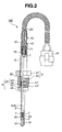
- FIG. 2 is a sectional view of a temperature sensor equipped with the thermistor element according to one embodiment of the present invention.
- FIG. 3 is a scanning electron microscopic (SEM) picture showing one example of material structure of the thermistor element according to one embodiment of the present invention.
- a thermistor element 2 that includes a body part 1 having a thermistor body 1a and a reduction-resistant coating 1b and a pair of electrode wires 2a and 2b embedded at respective one ends thereof in the thermistor body part 1.
- the thermistor body part 1 is formed into a hexagonal plate shape.
- the thermistor body 1a has electrical conductivity and contains a perovskite phase formed with a perovskite-type crystal structure as represented by the composition formula: ABO 3 .
- Each of the A-site and the B-site of the perovskite phase is occupied by one or more metal elements.
- Specific examples of the A-site element(s) are metal elements of group 2A and metal elements of group 3A other than La.
- Specific examples of B-site element(s) are Al and metal elements of groups 4A, 5A, 6A, 7A and 8.
- the perovskite phase has a composition of (M1, M2)(M3, Cr, Al)O 3 where M1 is at least one of the metal elements of group 3A other than La; M2 is at least one of the metal elements of group 2A; and M3 is at least one of the metal elements of groups 4A, 5A, 6A, 7A and 8 other than Cr.
- the perovskite phase has a composition of (Y, Sr)(Mn, Cr, Al)O 3 in order for the thermistor body 1a to show a suitable temperature gradient constant (B-value B(-40 ⁇ 900)) of 2000 to 3000 K in the range of -40 to 900°C for proper temperature measurements.
- the B-value B(-40 ⁇ 900) of the thermistor body 1a is desirably 2000 to 2900 K, more desirably 2000 to 2800 K.
- the elements of groups 2A, 3A, 4A, 5A, 6A and 7A in the present embodiment correspond to those of groups 2, 3, 4, 5, 6 and 7 in the IUPAC system, respectively; and the elements of group 8 in the present embodiment corresponds to those of group 8, 9 and 10 in the IUPAC system.
- the perovskite phase There is a possibility of excess or lack of oxygen in the perovskite phase depending on the sintering conditions (such as a sintering atmosphere e.g. oxidation/reduction atmosphere and a sintering temperature) of the thermistor material for production of the thermistor element 2 and the degree of substitution of the constituent elements of the A-site and the B-site of the perovskite phase.
- the molar ratio between the oxygen atom and the A-site element(s) and the molar ratio between the oxygen atom and the B-site element(s) may not be thus truly 3:1 as long as the perovskite phase maintains its perovskite-type crystal structure.
- the reduction-resistant coating 1b is applied to the thermistor body 1a in such a manner as to cover the thermistor body 1a densely by the reduction-resistant coating 1b.
- the reduction-resistant coating 1b is formed of a complex oxide containing at least one A-site element and at least one B-site element of the perovskite phase of the thermistor body 1a.
- a complex oxide e.g. YAlO 3 , Y 3 Al 5 O 12
- Sr-A1 oxides e.g. SrAl 2 O 4
- a plurality of complex oxide compounds may be used in combination. It is unlikely that only one of the metal elements of the perovskite phase will migrate alone to the reduction-resistant coating 1b (the complex oxide) even if the thermistor element 2 is subjected to high temperatures for a long time.
- the metal element of the perovskite phase is of the same kind as the metal element of the complex oxide, this metal element is particularly unlikely to migrate to the reduction-resistant coating 1b due to its small concentration gradient. It is also unlikely that either one of the metal elements of the reduction-resistant coating 1b (the complex oxide) will migrate alone to the perovskite phase even if the thermistor element 2 is subjected to high temperatures for a long time.
- the metal element of the reduction-resistant coating 1b is of the same kind as the metal element of the perovskite phase, this metal element is particularly unlikely to migrate to the perovskite phase due to its small concentration gradient.
- the thermistor element 2 is therefore able to achieve stable resistance characteristics for proper temperature measurements even if placed under high temperature conditions of over 600°C for a long time in a reducing atmosphere.
- the reduction-resistant coating 1b is preferably lower in conductivity than the thermistor body 1a and is more preferably electrically insulative so that the resistance of the thermistor element 2 is in general determined depending on the resistance of the thermistor body 1a.
- both of the A-site of the perovskite phase and the complex oxide contain at least either Sr or Y and, at the same time, both of the B-site of the perovskite phase and the complex oxide contain Al.
- the complex oxide of at least either Sr or Y and A1 is stable under high temperature conditions and shows excellent reduction resistance.
- Sr, Y and Al are suitable as the A-site element and B-site element of the perovskite phase, respectively, as mentioned above.
- compositions of the thermistor body 1a and of the reduction-resistant coating 1b are unlikely to vary due to metal migration between the perovskite phase and the reduction-resistant coating 1b when the metal elements of the complex oxide are the same as the A-site and B-site elements of the perovskite phase.
- the thermistor element 2 becomes thus able to attain more stable characteristics upon selection of at least either Sr or Y as the A-site element of the perovskite phase and the constituent element of the complex oxide and Al as the B-site element of the perovskite phase and the constituent element of the complex oxide.
- the A-site of the perovskite phase contains Sr
- the B-site of the perovskite phase contains A1
- the complex oxide is SrAl 2 O 4 .
- the complex oxide SrAl 2 O 4 is stable under high temperature conditions and shows excellent reduction resistance
- Sr and Al are suitable as the A-site element and B-site element of the perovskite phase, respectively.
- the thermistor element 2 becomes thus able to attain stable characteristics assuredly upon selection of Sr as the A-site element of the perovskite phase and the constituent element of the complex oxide and Al as the B-site element of the perovskite phase and the constituent element of the complex oxide.
- the thermistor body 1a contains at least one metal oxide phase lower in conductivity than the perovskite phase and represented by the composition formula: MeO x where Me is at least one selected from the metal elements of the perovskite phase.
- Me is at least one selected from the metal elements of the perovskite phase.
- the metal element Me is different from the metal element of the perovskite phase, there arises a possibility that the characteristics of the thermistor body 1a change with the formation of an unexpected by-product (by-product phase) other than the perovskite phase and the metal oxide phase in the thermistor body 1a. There also arises a possibility that the characteristics of the thermistor body 1a change with variations in compositions due to metal migration between the perovskite phase and the metal oxide phase.
- the metal element Me is the same as the metal element of the perovskite phase so that the thermistor element 2 becomes able to attain stable resistance characteristics, with no unexpected by-product formation and with no or little variations in compositions, even if subjected to high temperatures for a long time.
- the metal oxide phase is a phase of a metal oxide having a crystal structure represented by the composition formula: MeO x where Me is at least one selected from the metal elements of the perovskite phase.
- a metal oxide are single-metal oxides e.g. Y 2 O 3 , SrO, CaO, MnO 2 , Al 2 O 3 and Cr 2 O 3 and complex oxides such as Y-Al oxides e.g. YAlO 3 and Y 3 Al 5 O 12 and Sr-Al oxides e.g. SrAl 2 O 4 when the perovskite phase has a composition of (Y, Sr)(Mn, Cr, Al)O 3 .
- a plurality of metal oxide compounds may be contained in combination.
- the metal oxide phase is of the same complex oxide as that of the reduction-resistant coating 1b.
- metal migration between the metal oxide phase and the reduction-resistant coating 1b is unlikely to occur even if the thermistor element 2 is subjected to high temperatures for a long time. It becomes thus possible to limit variations in the compositions of the metal oxide phase and the reduction-resistant coating 1 b and provide the thermistor element 2 with stable characteristics. Further, there is no difference in thermal expansion coefficient between the metal oxide phase and the reduction-resistant coating 1b so that the metal oxide phase and the reduction-resistant coating 1b can be readily integrated with each other to achieve secure adhesion between the thermistor body 1 a and the reduction-resistant coating 1b.
- thermistor element 2 it is further preferable to produce thermistor element 2 by forming a green (unsintered) thermistor material into a desired shape, applying a green (unsintered) coating material to the thermistor material, and then, sintering the thermistor material and the coating material simultaneously to complete the thermistor body 1a and the reduction-resistant coating 1b.
- the simultaneous sintering of the thermistor material and the coating material allows easier production of the thermistor element 2 with the thermistor body 1 a and the reduction-resistant coating 1 b as compared to the case of producing the thermistor element 2 by sintering the thermistor material to complete the thermistor body 1a, applying the coating material to the thermistor body 1a and then sintering the coating material to complete the reduction-resistant coating 1b.
- This also makes it possible to reduce characteristics variations between individual samples of the thermistor element 2 and between different sintering lots of samples of the thermistor element 2 with little influence of fluctuations of the sintering conditions.
- the coating material is preferably in the form of a slurry containing therein the complex oxide.
- the use of the slurry containing therein the complex oxide as the coating material allows easy application of the coating material and makes it possible to limit the influence of sintering of the coating material on the thermistor body 1 a (perovskite phase, metal oxide phase) and the reduction-resistant coating 1b as compared to the case of forming the complex oxide during the sintering.
- the thermistor element 2 is suitably used as a temperature-sensing element of a temperature sensor 100.
- the temperature sensor 100 is designed to detect the temperature of exhaust gas in an exhaust pipe of an automotive engine by being mounted on a sensor mount portion of the exhaust pipe with the thermistor element 2 located in the exhaust pipe.
- the temperature sensor 100 includes a metal tube 3, a flange member 4, an attachment member 5, a metal cover member 6, a sheath member 8, a cement material 10, crimp terminals 11, lead wires 12, an elastic seal member 13, insulating tubes 15 and a glass braided tube 20 in addition to the thermistor element 2.
- the metal tube 3 is formed into a bottomed cylindrical shape along the axial direction of the sensor 100 and has a closed front end portion 31 (on the bottom side in FIG. 2) in which the thermistor element 2 is installed and a open rear end portion 32 (on the top side in FIG. 2) press-fitted in the flange member 4.
- the metal tube 3 has previously been heat-treated so that the outer and inner surfaces of the metal tube 3 become oxidized to form an oxide coating film on the outer and inner surfaces of the metal tube 3.
- the cement material 10 is filled in the metal tube 3 so as to surround the thermistor element 2 and thereby hold the thermistor element 2 in position.
- the flange member 4 includes a cylindrical shell 42 extending in the axial direction of the sensor 100 and a flange 41 located on a front side of the shell 42 (on the bottom side in FIG. 2) and having a larger outer diameter than that of the shell 42 to protrude radially outwardly from the shell 42.
- the flange member 41 also includes a tapered seat surface 45 formed on a front end of the flange 41 to seal the mount portion of the exhaust pipe.
- the shell 42 has a stepped shape with a front shell portion 44 and a rear shell portion 43 smaller in diameter than the front shell portion 44.
- the metal tube 3 is held securely in the flange member 4 by press-fitting the rear end portion 32 of the metal tube 3 through the flange member 4 and laser-welding an outer surface of the metal tube 3 to the rear shell portion 43 of the flange member 4 at a location L1 throughout the circumference.
- the metal cover member 6 is airtightly joined to the front shell portion 44 of the flange member 4 by press-fitting the metal cover member 6 in the front shell portion 44 of the flange member 4 and laser-welding the metal cover member 6 to the front shell portion 44 of the flange member 4 at a location L2 throughout the circumference.
- the attachment member 5 is provided with a hexagonal nut 51 and a screw 52 and is rotatably fixed around the flange member 4 and the metal cover member 6 so that the temperature sensor 100 is attached to the exhaust pipe (not shown) by screwing the nut 5 into the sensor mount portion of the exhaust pipe with the seat surface 45 on the flange 41 of the flange member 4 held in contact with the sensor mount portion of the exhaust pipe.
- the sheath member 8 is arranged in the metal tube 3, the flange member 4 and the metal cover member 6.
- the sheath member 8 includes a metallic outer casing 81, a pair of conductive core wires 7 passed through the outer casing 81, an insulative powder material filled in the outer casing 81 in such a manner as to establish electrical insulation between the outer casing 81 and the core wires 7 and hold the core wires 7 in position.
- the outer casing 81 of the sheath member 8 has also previously been heat-treated to form an oxide coating film on the outer casing 81 of the sheath member 8.
- the core wires 7 have front and rear end portions protruded from the front and rear ends of the outer casing 81, respectively.
- the protruded front end portions of the core wires 7 are connected within the metal tube 3 to the electrode wires 2a and 2b of the thermistor element 2 by laser welding, whereas the protruded rear end portions of the core wires 7 are connected to the lead wires 12 via the crimp terminals 11.
- the insulating tubes 15 are arranged to provide electrical insulation between the core wires 7 and between the crimp terminals 11.
- the lead wires 12 pass through lead wire insertion holes of the seal member 13, which is fitted in the rear end portion of the metal cover member 6, extend from inside to outside of the metal cover member 6, and then, are coupled to terminals of a connector 21 for connection to an external circuit (such as ECU, not shown).
- an external circuit such as ECU, not shown.
- the output of the thermistor element 2 is sent from the core wires 7 of the sheath member 8 to the external circuit through the lead wires 12 and the connector 21 so as to determine the temperature of the exhaust gas in the automotive engine.
- the lead wires 12 are covered by the glass braided tube 20.
- the glass braided tube 20 is crimped at a front end thereof into the metal cover member 6 together with the elastic seal member 13.
- the thermistor body 1 is protected from thermal reduction by means of the reduction-resistant coating 1a, for example, when there occurs a break or defect in the oxide coating film of the metal tube 3 or the outer casing 81 of the sheath member 8 or even when the thermistor element 2 is subjected to a reducing atmosphere under high temperature conditions due to such a break or defect in the oxide coating film.
- the thermistor element 2 is therefore able to maintain its resistance value and characteristics stably so that the temperture sensor 100 can carry out proper temperature measurements over the wide temperature range of -40°C to 900°C.
- Thermistor element 2 according to Examples 1 to 4 and thermistor elements according to Comparative Examples 1 to 3 were produced as follows.
- the resultant powder mixture was calcined at 1400°C for 2 hours in the air to provide a calcined powder material for perovskite phase formation with an average grain size of 1 to 2 ⁇ m.
- powders of SrCO 3 and Al 2 O 3 both commercially available at purity of 99% or greater were weighed to attain a composition of SrAl 2 O 4 , followed by subjecting these powders to wet mixing and drying.
- the resultant powder mixture was calcined at 1200°C for 2 hours in the air to provide a calcined powder material for metal oxide phase formation with an average grain size of 1 to 2 ⁇ m.
- the calcined perovskite-phase forming material and the calcined metal-oxide-phase forming material were weighed and subjected to wet grinding with a resin pot and a high-purity Al 2 O 3 ball using ethanol as a solvent, thereby yielding a slurry of thermistor composition material.
- the resultant powder mixture was calcined at 1200°C for 2 hours in the air to provide a calcined powder material for perovskite phase formation with an average grain size of 1 to 2 ⁇ m.
- the calcined perovskite-phase forming material was subjected to wet grinding with a resin pot and a high-purity Al 2 O 3 ball using ethanol as a solvent, thereby yielding a slurry of thermistor composition material.
- the thus-obtained slurry was dried at 80°C for 2 hours to provide a powdery thermistor composition material.
- the thermistor composition material 100 parts by weight the thermistor composition material and 20 parts by weight a binder predominantly composed of polyvinyl butyral were mixed, dried and granulated with a 250- ⁇ m mesh screen.
- the binder is not particularly restricted to the polyvinyl butyral. Any other binder such as polyvinyl alcohol or acrylic binder can alternatively be used.
- the blending amount of the binder is generally 5 to 20 parts by weight, preferably 10 to 20 parts by weight, with respect to the total amount of the thermistor composition material. It is further desirable to control the average grain size of the thermistor composition material to 2.0 ⁇ m or smaller in order for the thermistor composition material and the binder to be mixed uniformly.
- the granulated thermistor composition material was subjected to die-press forming with a press pressure of 4500 kg/cm 2 , thereby forming a green compact of hexagonal plate shape with a thickness of 1.24 mm in thickness.
- electrode wires 2a and 2b of Pt-Rh alloy were embedded at their respective one ends in the green compact.
- electrode wires of Pt-Rh alloy were embedded at their respective one ends in the green compact in Comparative Examples 1 to 3.
- a slurry of the complex-oxide coating material was obtained by kneading the powdery complex-oxide material with a binder predominantly composed of ethyl cellulose with a mortar and a pestle using butyl carbinol and acetone as a solvent.
- the green compact of the thermistor composition material except the electrode wires 2a and 2b was dip-coated with the slurry of the complex-oxide material.
- the thermistor element 2 was completed by, after drying the slurry, sintering the slurry-coated compact (sintering the thermistor composition material and the complex-oxide material simultaneously) at 1450 to 1550°C in the air so as to form a thermistor body 1a of the thermistor composition material and a reduction-resistant coating 1b of the complex-oxide material.
- the thermistor body 1a had a hexagonal shape with a side length of 1.15 mm and a thickness of 1.00 mm, the reduction-resistant coating 1b had a thickness of 10 to 50 ⁇ m, and the electrode wires 2a and 2b had a diameter ⁇ of 0.3 mm with a electrode center distance of 0.74 mm (a gap of 0.44 mm) and an electrode insertion length of 1.10 mm.
- Example 2 the green compact of the thermistor composition material was first sintered at 1450 to 1550°C in the air so as to form a thermistor body 1a of the thermistor composition material.
- the sintered compact except the electrode wires 2a and 2b was next dip-coated with the slurry of the complex-oxide material.
- the thermistor element 2 was then completed by, after drying the slurry, sintering the slurry-coated compact again so as to form a reduction-resistant coating 1b of the complex-oxide material.
- the thermistor body 1a had a hexagonal shape with a side length of 1.15 mm and a thickness of 1.00 mm, the reduction-resistant coating 1 b had a thickness of 10 to 50 ⁇ m, and the electrode wires 2a and 2b had a diameter ⁇ of 0.3 mm with a electrode center distance of 0.74 mm (a gap of 0.44 mm) and an electrode insertion length of 1.10 mm.
- Comparative Examples 1 and 2 the thermistor elements were completed in the same manner as in Examples 1, 3 and 4.
- the thermistor element was completed in Comparative Example 3 in the same manner as in Example 2.
- Example 2 and of Comparative Example 3 were Y 3 Al 5 O 12 , which has a higher sintering temperature than those of the thermistor composition materials of Example 2 and of Comparative Example 3.
- the thermistor body 1a and the reduction-resistant coating 1 b were thus formed step by step by sintering the thermistor composition material and then sintering the complex-oxide coating material as explained above. This led to easier and lower-cost production of the thermistor element 2 in Examples 1, 3 and 4 than in Example 2.
- the thermistor elements 2 of Examples 1 to 4 and the thermistor elements of Comparative Examples 1 to 3 were tested for their reduction resistance as follows.
- the thermistor element 2 was left for 1 hour in the reducing atmosphere, to measure the resistance value Rk'(1000) of the thennistor element 2 at 1000°C under the reducing atmosphere.
- the amount ⁇ Rk (%) of change in resistance was calculated from the measurement values Rk(1000) and Rk'(1000), according to the following equation (1), as an index of the resistance of the coating 1b to thermal reduction as well as the ability of the coating 1b to protect the thermistor body 1a from the reducing atmosphere.
- ⁇ Rk % 100 - Rk 1000 / Rk ⁇ 1000 ⁇ 100
- the resistance change amount ⁇ Rk (%) of the thermistor element according to each of Comparative Examples 1 to 3 was determined in the same manner as in Examples 1 to 4.
- the thermistor elements 2 of Examples 1 to 4 and the thermistor elements of Comparative Examples 1 to 3 had a small resistance change amount ⁇ Rk of at most ⁇ 5%. It is thus apparent that all of the reduction-resistant coatings 1b of Examples 1 to 4 and the reduction-resistant coatings of Comparative Examples 1 to 3 had high reduction resistance and thermistor protection ability.
- the thermistor elements 2 of Examples 1 to 4 and the thermistor elements of Comparative Examples 1 to 3 were also tested for their resistance characteristics as follows.
- the B-value B(-40 ⁇ 900) of the thermistor element 2 was calculated from the measurement values Rs(-40) and Rs(900) according to the following equation (2). The test results are indicated in TABLE 2.
- B ⁇ - 40 ⁇ 900 ln ⁇ Rs 900 / Rs - 40 / 1 / T 900 - 1 / T - 40
- the temperature gradient constant (B-value) B(-40 ⁇ 900) of the thermistor element according to each of Comparative Examples 1 to 3 was determined in the same manner as in Examples 1 to 3. The test results are also indicated in TABLE 2.
- Each of the thermistor elements 2 of Examples 1 to 4 was built into a temperature sensor 100.
- the surroundings of the temperature sensor 100 was heated to 100°C, 300°C, 600°C and then 900°C, to measure the initial resistance values Rt(100), Rt(300), Rt(600) and Rt(900) of the thermistor element 2 at 100°C, 300°C, 600°C and 900°C.
- the temperature sensor 100 was maintained at 1050°C in the air for 50 hours. After that, the resistance values Rt'(100), Rt'(300), Rt'(600) and Rt'(900) of the thermistor element 2 were measured at 100°C, 300°C, 600°C and 900°C in the same manner as above.
- the temperature conversion value CT(900) (deg) of the resistance change under the heat treatment was calculated according to the following equation (4).
- the temperature conversion values CT(100), CT(300) and CT(600) (deg) were calculated according to the following equations (5) to (7).
- the B-value B(100 ⁇ 900) was used in place of B(-40 ⁇ 900) in the equations (4) to (7) for calculation of the conversion values CT(900), CT(100), CT(300) and CT(600) (deg).
- the test results are indicated in TABLE 2.
- the surface area fraction SP/S of a perovskite phase of the thermistor body 1a according to each of Examples 1 to 4 was determined as follows.
- the thermistor body part 1 was embedded in a resin and subjected to buffing using 3- ⁇ m diamond past to provide a test sample of thermistor body 1a with a buffed cross section.
- a picture of the cross section of the test sample was taken with a magnification of 3000 times using a scanning electron microscope (available under the trade name of "JSM-6460LA” from JEOL Ltd.).
- JSM-6460LA scanning electron microscope
- white, dark gray and black areas of the SEM picture were determined by EDS chemical composition analysis to be a perovskite phase ((YSr)(MnCrAl)O 3 ), a metal oxide phase (SrAl 2 O 4 ) and pores, respectively. It has been shown in FIG. 3 that the perovskite phase and the metal oxide phase are dispersed through the thermistor body 1a in Example 1. The same applied to Examples 2 to 4. A field of view of 40 ⁇ m ⁇ 30 ⁇ m in the SEM picture was analyzed by means of an image analysis device, thereby determining the proportion (surface area fraction) SP/S of the cross sectional area SP of the perovskite phase to the field of view (cross sectional area S).
- the test results are indicated in TABLE 2.
- the proportion of a cross sectional area of one specific phase in a given cross sectional area of the thermistor body is equivalent to the volume fraction of such one specific phase in the thermistor oxide.
- the thermistor body 1a had two phases: perovskite phase and metal oxide phase. It means that the surface area fraction SP/S is substantially equal to a surface or volume ratio between the perovskite phase and the metal oxide phase.
- the thermistor elements 2 of Examples 1 to 4 had relatively small conversion values CT(100), CT(300), CT(600) and CT(900) of at most ⁇ 3 deg as compared to those of Comparative Examples 1 to 3 as shown in TABLE 2. The reason for this is estimated as follows.
- the reduction-resistant coating did not contain a complex oxide but contained a single-metal oxide Y 2 O 3 or Al 2 O 3 so that there occurred migration of the metal element Sr, Mn, Cr, Al from the perovskite phase to the reduction-resistant coating and migration of the metal element Y, Al from the reduction-resistant coating to the perovskite phase.
- the reduction-resistant coating contained a complex oxide Y 3 Al 5 O 12 but the metal element Al of the complex oxide was different from the B-site element Cr of the perovskite phase so that the there occurred migration of the metal element Cr from the perovskite phase to the reduction-resistant coating and migration of the metal element A1 from the reduction-resistant coating to the perovskite phase.
- the resistance characteristics of the thermistor body changed due to variations in the compositions of the perovskite phase and the reduction-resistant coating, thereby resulting in the above relatively large conversion values CT(100), CT(300), CT(600) and CT(900) in Comparative Examples 1 to 3.
- the metal elements Sr or Y and Al of the complex oxide of the reduction-resistant coating 1b were the same as the A-site element Sr, Y and the B-site element Al of the perovskite phase of the thermistor body 1a. Variations in the compositions of the perovskite phase and the reduction-resistant coating 1b was limited from being caused due to metal migration between the perovskite phase and the reduction-resistant coating 1b even if the thermistor element 2 was subjected to high temperatures for a long time. As a result, each of the thermistor elements 2 of Examples 1 to 4 had a stable resistance value at each measurement temperture and showed a small amount of change in resistance under high temperature conditions. The resistance values of these thermistor elements 2 could be measured stably, regardless of their thermal histories, for proper temperature measurements.
- the thermistor elements 2 of Examples 1, 3 and 4 generally had smaller conversion values CT(100), CT(300), CT(600) and CT(900) than those of Example 2. It can be thus said that SrAl 2 O 4 was more suitable as the complex oxide of the reduction-resistant coating 1b.
- the metal oxide phase of the thermistor body 1a and the reduction-resistant coating 1b were of the same complex oxide so that the reduction-resistant coating 1b was securely adhered to the thermistor body 1a to provide high durability because of no difference in thermal expansion coefficient between the metal oxide phase and the reduction-resistant coating 1b (the complex oxide).
- the thermistor element 2 of the present embodiment shows a suitable B-value of 2000 to 3000 K as well as a suitable resistance value so as to enable proper temperature measurements over the wide temperature range of a low temperature of -40°C to a high temperature of 900°C.
- various compounds including not only oxides but also carbonates, hydroxides and nitrates of the respective constituent elements of the thermistor body 1a and the reduction-resistant coating 1b are usable as raw materials for production of the thermistor element 2.
- oxide and carbonate are preferred.
- the thermistor body 1a and the reduction-resistant coating 1b may contain any other element or elements such as Na, K, Ga, Si, C, Cl and S on condition that the characteristics required of the thermistor body 1a, the reduction-resistant coating 1b, the thermistor element 2 and the temperature sensor 100 (such as the sinterability, B-value, high-temperature stability and reduction resistance of the thermistor body 1a and the reduction-resistant coating 1b) do not deteriorate.
- any other element or elements such as Na, K, Ga, Si, C, Cl and S on condition that the characteristics required of the thermistor body 1a, the reduction-resistant coating 1b, the thermistor element 2 and the temperature sensor 100 (such as the sinterability, B-value, high-temperature stability and reduction resistance of the thermistor body 1a and the reduction-resistant coating 1b) do not deteriorate.
- the oxide coating films may not be formed on the metal tube 3 and the outer casing 81 of the sheath member 8 when the reduction-resistance coating 1b provides sufficient, favorable reduction resistance.
Landscapes
- Engineering & Computer Science (AREA)
- Chemical & Material Sciences (AREA)
- Organic Chemistry (AREA)
- Microelectronics & Electronic Packaging (AREA)
- Inorganic Chemistry (AREA)
- Materials Engineering (AREA)
- Ceramic Engineering (AREA)
- Electromagnetism (AREA)
- Physics & Mathematics (AREA)
- Life Sciences & Earth Sciences (AREA)
- General Life Sciences & Earth Sciences (AREA)
- Geology (AREA)
- Manufacturing & Machinery (AREA)
- Structural Engineering (AREA)
- Thermistors And Varistors (AREA)
Abstract
The reduction-resistant coating (1b) is formed of a complex oxide containing one or more of the at least one A-site element and one or more of the at least one B-site element.
Description
- The present invention relates to a thennistor element, a thermistor element production method and a thermistor temperture sensor.
- A thermistor element is generally produced from a sintered conductive oxide that shows a change in resistance (specific resistance) with a change of temperature and is suitably used in a temperature sensor.
Japanese Laid-Open Patent Publication No. 11-251109 - In the case of using the thermistor element or thermistor temperature sensor in an internal combustion engine to measure the temperature of engine exhaust gas, there has recently been a demand for the thermistor element to enable temperature measurements in a high temperature range of around 900°C for the protection of a diesel particulate filter (DPF) and a NOx reduction catalyst in the engine. There has also been a demand for the thermistor element to enable temperature measurements in a low temperature range for the application of on-board diagnostics (OBD). The thermistor element may thus be required to carry out temperature measurements over the wide range from a low temperature of -40°C to a high temperature of 900°C or higher. In order to protect the thermistor element from condensation and soot in the measurement gas during the temperature measurements over such a wide temperature range, a metal tube of e.g. stainless alloy is provided to accommodate therein the thermistor element.
- However, the metal tube is oxidized to create a reducing atmosphere in the interior of the metal tube when the temperature of the metal tube exceeds 600°C or higher. The thermistor element is then reduced in the reducing atmosphere so that the resistance (characteristics) of the thermistor element becomes changed.
- It is conceivable to heat-treat the metal tube previously so as to form a coating of metal or metal oxide on an inner surface of the metal tube and protect the metal tube from thermal oxidation under high temperature conditions. However, the metal or metal oxide coating may be broken due to vibrations during the use of the thermistor element (temperature sensor) or may have a defect in itself. When the metal tube is oxidized through such a break or defect of the coating, the thermistor element is reduced to cause a change in thermistor resistance (characteristics).
- On the other hand,
Japanese Laid-Open Patent Publication No. 11-251109 Japanese Laid-Open Patent Publication No. 11-251109 - It is therefore an object of the present invention to provide a thermistor element for enabling proper temperature measurements over the wide range from a low temperature to a high temperature of over 600°C while limiting the occurrence of a secular change in thermistor resistance (characteristics) even if placed under high temperature conditions in a reducing atmosphere. It is also an object of the present invention to provide a production method of the thermistor element and a temperature sensor using the thermistor element.
- According to a first aspect of the present invention, there is provided a thermistor element, comprising: a thermistor body containing a perovskite phase of perovskite-type crystal structure represented by the composition formula: ABO3 where A is at least one A-site element and B is at least one B-site element; and a reduction-resistant coating covering the thermistor body and formed of a complex oxide containing one or more of the at least one A-site element and one or more of the at least one B-site element.
- According to a second aspect of the present invention, there is provided a method for producing a thermistor element, the thermistor element having a thermistor body containing a perovskite phase of perovskite-type crystal structure represented by the composition formula: ABO3 where A is at least one A-site element and B is at least one B-site element and a reduction-resistant coating covering the thermistor body and formed of a complex oxide containing one or more of the at least one A-site element and one or more of the at least one B-site element, the method comprising: forming a green thermistor composition material into a desired shape; applying a green coating material to a surface of the green thermistor composition material; and then sintering the thermistor composition material and the coating material simultaneously in such a manner that the thermistor body and the reduction-resistant coating are produced from the sintered thermistor composition material and the sintered coating material, respectively.
- According to a third aspect of the present invention, there is provide a temperature sensor comprising: a thermistor element having a thermistor body containing a perovskite phase of perovskite-type crystal structure represented by the composition formula: ABO3 where A is at least one A-site element and B is at least one B-site element; and a reduction-resistant coating covering the thermistor body and formed of a complex oxide containing one or more of the at least one A-site element and one or more of the at least one B-site element.
- The other objects and features of the present invention will also become understood from the following description.
- FIG. 1 A is a perspective view of a thermistor element according to one embodiment of the present invention.
- FIG. 1 B is a sectional view of the thermistor element according to one embodiment of the present invention.
- FIG. 2 is a sectional view of a temperature sensor equipped with the thermistor element according to one embodiment of the present invention.
- FIG. 3 is a scanning electron microscopic (SEM) picture showing one example of material structure of the thermistor element according to one embodiment of the present invention.
- The present invention will be described below in detail with reference to the drawings.
- As shown in FIGS. 1A and 1B, there is provided according to one embodiment of the present invention a
thermistor element 2 that includes abody part 1 having athermistor body 1a and a reduction-resistant coating 1b and a pair ofelectrode wires thermistor body part 1. In the present embodiment, thethermistor body part 1 is formed into a hexagonal plate shape. - The
thermistor body 1a has electrical conductivity and contains a perovskite phase formed with a perovskite-type crystal structure as represented by the composition formula: ABO3. Each of the A-site and the B-site of the perovskite phase is occupied by one or more metal elements. Specific examples of the A-site element(s) are metal elements of group 2A and metal elements of group 3A other than La. Specific examples of B-site element(s) are Al and metal elements of groups 4A, 5A, 6A, 7A and 8. In order for thethermistor body 1a to achieve appropriate electrical conductivity and enable temperature measurements over the wide range from a low temperature to a high temperature of over 600°C, it is preferable that the perovskite phase has a composition of (M1, M2)(M3, Cr, Al)O3 where M1 is at least one of the metal elements of group 3A other than La; M2 is at least one of the metal elements of group 2A; and M3 is at least one of the metal elements of groups 4A, 5A, 6A, 7A and 8 other than Cr. More preferably, the perovskite phase has a composition of (Y, Sr)(Mn, Cr, Al)O3 in order for thethermistor body 1a to show a suitable temperature gradient constant (B-value B(-40~900)) of 2000 to 3000 K in the range of -40 to 900°C for proper temperature measurements. The B-value B(-40~900) of thethermistor body 1a is desirably 2000 to 2900 K, more desirably 2000 to 2800 K. - It is noted that: the elements of groups 2A, 3A, 4A, 5A, 6A and 7A in the present embodiment correspond to those of
groups group 8, 9 and 10 in the IUPAC system. - There is a possibility of excess or lack of oxygen in the perovskite phase depending on the sintering conditions (such as a sintering atmosphere e.g. oxidation/reduction atmosphere and a sintering temperature) of the thermistor material for production of the
thermistor element 2 and the degree of substitution of the constituent elements of the A-site and the B-site of the perovskite phase. The molar ratio between the oxygen atom and the A-site element(s) and the molar ratio between the oxygen atom and the B-site element(s) may not be thus truly 3:1 as long as the perovskite phase maintains its perovskite-type crystal structure. - The reduction-resistant coating 1b is applied to the
thermistor body 1a in such a manner as to cover thethermistor body 1a densely by the reduction-resistant coating 1b. By the application of the reduction-resistant coating 1b to thethermistor body 1 a, it is possible to protect thethermistor body 1 a from reduction and thereby prevent the resistance (characteristics) of thethermistor body 1a from changing when thethermistor element 2 is placed in a reducing atmosphere under high temperature conditions. - Further, the reduction-resistant coating 1b is formed of a complex oxide containing at least one A-site element and at least one B-site element of the perovskite phase of the
thermistor body 1a. Examples of such a complex oxide are Y-Al oxides (e.g. YAlO3, Y3Al5O12) and Sr-A1 oxides (e.g. SrAl2O4). A plurality of complex oxide compounds may be used in combination. It is unlikely that only one of the metal elements of the perovskite phase will migrate alone to the reduction-resistant coating 1b (the complex oxide) even if thethermistor element 2 is subjected to high temperatures for a long time. When the metal element of the perovskite phase is of the same kind as the metal element of the complex oxide, this metal element is particularly unlikely to migrate to the reduction-resistant coating 1b due to its small concentration gradient. It is also unlikely that either one of the metal elements of the reduction-resistant coating 1b (the complex oxide) will migrate alone to the perovskite phase even if thethermistor element 2 is subjected to high temperatures for a long time. When the metal element of the reduction-resistant coating 1b is of the same kind as the metal element of the perovskite phase, this metal element is particularly unlikely to migrate to the perovskite phase due to its small concentration gradient. It is thus possible to limit variations in the compositions of thethermistor body 1a and the reduction-resistant coating 1b due to metal migration between the perovskite phase and the reduction-resistant coating 1b (the complex oxide) and prevent the resistance values and characteristics of thethermistor body 1a and the reduction-resistant coating 1b from changing when thethermistor element 2 is placed under high temperature conditions for a long time. - The
thermistor element 2 is therefore able to achieve stable resistance characteristics for proper temperature measurements even if placed under high temperature conditions of over 600°C for a long time in a reducing atmosphere. - In the present embodiment, the reduction-resistant coating 1b is preferably lower in conductivity than the
thermistor body 1a and is more preferably electrically insulative so that the resistance of thethermistor element 2 is in general determined depending on the resistance of thethermistor body 1a. - It is particularly desirable that both of the A-site of the perovskite phase and the complex oxide contain at least either Sr or Y and, at the same time, both of the B-site of the perovskite phase and the complex oxide contain Al. The complex oxide of at least either Sr or Y and A1 is stable under high temperature conditions and shows excellent reduction resistance. Further, Sr, Y and Al are suitable as the A-site element and B-site element of the perovskite phase, respectively, as mentioned above. In addition, the compositions of the
thermistor body 1a and of the reduction-resistant coating 1b are unlikely to vary due to metal migration between the perovskite phase and the reduction-resistant coating 1b when the metal elements of the complex oxide are the same as the A-site and B-site elements of the perovskite phase. Thethermistor element 2 becomes thus able to attain more stable characteristics upon selection of at least either Sr or Y as the A-site element of the perovskite phase and the constituent element of the complex oxide and Al as the B-site element of the perovskite phase and the constituent element of the complex oxide. - It is more desirable that the A-site of the perovskite phase contains Sr, the B-site of the perovskite phase contains A1 and the complex oxide is SrAl2O4. The complex oxide SrAl2O4 is stable under high temperature conditions and shows excellent reduction resistance, and Sr and Al are suitable as the A-site element and B-site element of the perovskite phase, respectively. The
thermistor element 2 becomes thus able to attain stable characteristics assuredly upon selection of Sr as the A-site element of the perovskite phase and the constituent element of the complex oxide and Al as the B-site element of the perovskite phase and the constituent element of the complex oxide. - Preferably, the
thermistor body 1a contains at least one metal oxide phase lower in conductivity than the perovskite phase and represented by the composition formula: MeOx where Me is at least one selected from the metal elements of the perovskite phase. Even when thethermistor element 2 is of any desired shape, it becomes thus possible to adjust the resistance of thethermistor body 1a, and by extension, the resistance of thethermistor element 2 appropriately while maintaining a suitable B-value by changing the proportion of the low-conductivity (highly-insulating) metal oxide phase in thethermistor body 1a. - If the metal element Me is different from the metal element of the perovskite phase, there arises a possibility that the characteristics of the
thermistor body 1a change with the formation of an unexpected by-product (by-product phase) other than the perovskite phase and the metal oxide phase in thethermistor body 1a. There also arises a possibility that the characteristics of thethermistor body 1a change with variations in compositions due to metal migration between the perovskite phase and the metal oxide phase. In the present embodiment, however, the metal element Me is the same as the metal element of the perovskite phase so that thethermistor element 2 becomes able to attain stable resistance characteristics, with no unexpected by-product formation and with no or little variations in compositions, even if subjected to high temperatures for a long time. - There is no particular restriction on the metal oxide phase as long as the metal oxide phase is a phase of a metal oxide having a crystal structure represented by the composition formula: MeOx where Me is at least one selected from the metal elements of the perovskite phase. Specific examples of such a metal oxide are single-metal oxides e.g. Y2O3, SrO, CaO, MnO2, Al2O3 and Cr2O3 and complex oxides such as Y-Al oxides e.g. YAlO3 and Y3Al5O12 and Sr-Al oxides e.g. SrAl2O4 when the perovskite phase has a composition of (Y, Sr)(Mn, Cr, Al)O3. A plurality of metal oxide compounds may be contained in combination.
- It is more preferable that the metal oxide phase is of the same complex oxide as that of the reduction-resistant coating 1b. In this case, metal migration between the metal oxide phase and the reduction-resistant coating 1b is unlikely to occur even if the
thermistor element 2 is subjected to high temperatures for a long time. It becomes thus possible to limit variations in the compositions of the metal oxide phase and the reduction-resistant coating 1 b and provide thethermistor element 2 with stable characteristics. Further, there is no difference in thermal expansion coefficient between the metal oxide phase and the reduction-resistant coating 1b so that the metal oxide phase and the reduction-resistant coating 1b can be readily integrated with each other to achieve secure adhesion between thethermistor body 1 a and the reduction-resistant coating 1b. - It is further preferable to produce
thermistor element 2 by forming a green (unsintered) thermistor material into a desired shape, applying a green (unsintered) coating material to the thermistor material, and then, sintering the thermistor material and the coating material simultaneously to complete thethermistor body 1a and the reduction-resistant coating 1b. The simultaneous sintering of the thermistor material and the coating material allows easier production of thethermistor element 2 with thethermistor body 1 a and the reduction-resistant coating 1 b as compared to the case of producing thethermistor element 2 by sintering the thermistor material to complete thethermistor body 1a, applying the coating material to thethermistor body 1a and then sintering the coating material to complete the reduction-resistant coating 1b. This also makes it possible to reduce characteristics variations between individual samples of thethermistor element 2 and between different sintering lots of samples of thethermistor element 2 with little influence of fluctuations of the sintering conditions. - The coating material is preferably in the form of a slurry containing therein the complex oxide. The use of the slurry containing therein the complex oxide as the coating material allows easy application of the coating material and makes it possible to limit the influence of sintering of the coating material on the
thermistor body 1 a (perovskite phase, metal oxide phase) and the reduction-resistant coating 1b as compared to the case of forming the complex oxide during the sintering. - As shown in FIG. 2, the
thermistor element 2 is suitably used as a temperature-sensing element of atemperature sensor 100. In the present embodiment, thetemperature sensor 100 is designed to detect the temperature of exhaust gas in an exhaust pipe of an automotive engine by being mounted on a sensor mount portion of the exhaust pipe with thethermistor element 2 located in the exhaust pipe. - The
temperature sensor 100 includes ametal tube 3, a flange member 4, anattachment member 5, a metal cover member 6, a sheath member 8, acement material 10,crimp terminals 11,lead wires 12, anelastic seal member 13, insulatingtubes 15 and aglass braided tube 20 in addition to thethermistor element 2. - The
metal tube 3 is formed into a bottomed cylindrical shape along the axial direction of thesensor 100 and has a closed front end portion 31 (on the bottom side in FIG. 2) in which thethermistor element 2 is installed and a open rear end portion 32 (on the top side in FIG. 2) press-fitted in the flange member 4. Themetal tube 3 has previously been heat-treated so that the outer and inner surfaces of themetal tube 3 become oxidized to form an oxide coating film on the outer and inner surfaces of themetal tube 3. Thecement material 10 is filled in themetal tube 3 so as to surround thethermistor element 2 and thereby hold thethermistor element 2 in position. - The flange member 4 includes a
cylindrical shell 42 extending in the axial direction of thesensor 100 and aflange 41 located on a front side of the shell 42 (on the bottom side in FIG. 2) and having a larger outer diameter than that of theshell 42 to protrude radially outwardly from theshell 42. Theflange member 41 also includes a taperedseat surface 45 formed on a front end of theflange 41 to seal the mount portion of the exhaust pipe. In the present embodiment, theshell 42 has a stepped shape with afront shell portion 44 and arear shell portion 43 smaller in diameter than thefront shell portion 44. - The
metal tube 3 is held securely in the flange member 4 by press-fitting therear end portion 32 of themetal tube 3 through the flange member 4 and laser-welding an outer surface of themetal tube 3 to therear shell portion 43 of the flange member 4 at a location L1 throughout the circumference. - The metal cover member 6 is airtightly joined to the
front shell portion 44 of the flange member 4 by press-fitting the metal cover member 6 in thefront shell portion 44 of the flange member 4 and laser-welding the metal cover member 6 to thefront shell portion 44 of the flange member 4 at a location L2 throughout the circumference. - The
attachment member 5 is provided with ahexagonal nut 51 and ascrew 52 and is rotatably fixed around the flange member 4 and the metal cover member 6 so that thetemperature sensor 100 is attached to the exhaust pipe (not shown) by screwing thenut 5 into the sensor mount portion of the exhaust pipe with theseat surface 45 on theflange 41 of the flange member 4 held in contact with the sensor mount portion of the exhaust pipe. - The sheath member 8 is arranged in the
metal tube 3, the flange member 4 and the metal cover member 6. The sheath member 8 includes a metallic outer casing 81, a pair ofconductive core wires 7 passed through the outer casing 81, an insulative powder material filled in the outer casing 81 in such a manner as to establish electrical insulation between the outer casing 81 and thecore wires 7 and hold thecore wires 7 in position. The outer casing 81 of the sheath member 8 has also previously been heat-treated to form an oxide coating film on the outer casing 81 of the sheath member 8. Thecore wires 7 have front and rear end portions protruded from the front and rear ends of the outer casing 81, respectively. The protruded front end portions of thecore wires 7 are connected within themetal tube 3 to theelectrode wires thermistor element 2 by laser welding, whereas the protruded rear end portions of thecore wires 7 are connected to thelead wires 12 via thecrimp terminals 11. The insulatingtubes 15 are arranged to provide electrical insulation between thecore wires 7 and between thecrimp terminals 11. - The
lead wires 12 pass through lead wire insertion holes of theseal member 13, which is fitted in the rear end portion of the metal cover member 6, extend from inside to outside of the metal cover member 6, and then, are coupled to terminals of aconnector 21 for connection to an external circuit (such as ECU, not shown). With this arrangement, the output of thethermistor element 2 is sent from thecore wires 7 of the sheath member 8 to the external circuit through thelead wires 12 and theconnector 21 so as to determine the temperature of the exhaust gas in the automotive engine. In order to protect thelead wires 12 from external force e.g. scattering stones, thelead wires 12 are covered by the glass braidedtube 20. The glass braidedtube 20 is crimped at a front end thereof into the metal cover member 6 together with theelastic seal member 13. - In the above-structured
temperature sensor 100, thethermistor body 1 is protected from thermal reduction by means of the reduction-resistant coating 1a, for example, when there occurs a break or defect in the oxide coating film of themetal tube 3 or the outer casing 81 of the sheath member 8 or even when thethermistor element 2 is subjected to a reducing atmosphere under high temperature conditions due to such a break or defect in the oxide coating film. Thethermistor element 2 is therefore able to maintain its resistance value and characteristics stably so that thetemperture sensor 100 can carry out proper temperature measurements over the wide temperature range of -40°C to 900°C. - The present invention will be described in more detail with reference to the following examples. It should be however noted that the following examples are only illustrative and not intended to limit the invention thereto.
-
Thermistor element 2 according to Examples 1 to 4 and thermistor elements according to Comparative Examples 1 to 3 were produced as follows. - In each of Examples 1 to 4 and Comparative Examples 1 and 2, powders of Y2O3, Nd2O3, SrCO3, MnO2, Fe2O3, Al2O3 and Cr2O3 (all commercially available at purity of 99% or greater) were weighed to attain a perovskite composition of (MlaM2b)(M3cAldCre)O3 by metal elements M1, M2 and M3 and mole fractions a, b, c, d and e as indicated in TABLE 1, followed by subjecting these powders to wet mixing and drying. The resultant powder mixture was calcined at 1400°C for 2 hours in the air to provide a calcined powder material for perovskite phase formation with an average grain size of 1 to 2 µm. On the other hand, powders of SrCO3 and Al2O3 (both commercially available at purity of 99% or greater) were weighed to attain a composition of SrAl2O4, followed by subjecting these powders to wet mixing and drying. The resultant powder mixture was calcined at 1200°C for 2 hours in the air to provide a calcined powder material for metal oxide phase formation with an average grain size of 1 to 2 µm. The calcined perovskite-phase forming material and the calcined metal-oxide-phase forming material were weighed and subjected to wet grinding with a resin pot and a high-purity Al2O3 ball using ethanol as a solvent, thereby yielding a slurry of thermistor composition material.
- In Comparative Example 3, powders of Y2O3 and Cr2O3 (both commercially available at purity of 99% or greater) were weighed to attain a mole ratio ofY : Cr = 1 : 1, i.e., to attain a composition of YCrO3, followed by subjecting these powders to wet mixing and drying. The resultant powder mixture was calcined at 1200°C for 2 hours in the air to provide a calcined powder material for perovskite phase formation with an average grain size of 1 to 2 µm. The calcined perovskite-phase forming material was subjected to wet grinding with a resin pot and a high-purity Al2O3 ball using ethanol as a solvent, thereby yielding a slurry of thermistor composition material.
- The thus-obtained slurry was dried at 80°C for 2 hours to provide a powdery thermistor composition material.
- Subsequently, 100 parts by weight the thermistor composition material and 20 parts by weight a binder predominantly composed of polyvinyl butyral were mixed, dried and granulated with a 250-µm mesh screen. It is herein noted that the binder is not particularly restricted to the polyvinyl butyral. Any other binder such as polyvinyl alcohol or acrylic binder can alternatively be used. The blending amount of the binder is generally 5 to 20 parts by weight, preferably 10 to 20 parts by weight, with respect to the total amount of the thermistor composition material. It is further desirable to control the average grain size of the thermistor composition material to 2.0 µm or smaller in order for the thermistor composition material and the binder to be mixed uniformly.
- The granulated thermistor composition material was subjected to die-press forming with a press pressure of 4500 kg/cm2, thereby forming a green compact of hexagonal plate shape with a thickness of 1.24 mm in thickness. In Examples 1 to 4,
electrode wires - Next, powders of SrCO3, Al2O3 and Y2O3 (all commercially available at purity of 99% or greater) were weighed to attain a complex oxide composition as indicated in TABLE 1 (SrAl2O4 in Examples 1, 3 and 4, Y3Al5O12 in Example 2 and Comparative Example 3, Y2O3 in Comparative Example 1 and Al2O3 in Comparative Example 2), followed by subjecting these powders to wet mixing and drying. The resultant powder mixture was calcined at 1200 to 1400°C for 2 hours in the air to provide a powdery complex-oxide coating material with an average grain size of 1 to 2 µm. A slurry of the complex-oxide coating material was obtained by kneading the powdery complex-oxide material with a binder predominantly composed of ethyl cellulose with a mortar and a pestle using butyl carbinol and acetone as a solvent.
- In each of Examples 1, 3 and 4, the green compact of the thermistor composition material except the
electrode wires thermistor element 2 was completed by, after drying the slurry, sintering the slurry-coated compact (sintering the thermistor composition material and the complex-oxide material simultaneously) at 1450 to 1550°C in the air so as to form athermistor body 1a of the thermistor composition material and a reduction-resistant coating 1b of the complex-oxide material. Thethermistor body 1a had a hexagonal shape with a side length of 1.15 mm and a thickness of 1.00 mm, the reduction-resistant coating 1b had a thickness of 10 to 50 µm, and theelectrode wires - In Example 2, the green compact of the thermistor composition material was first sintered at 1450 to 1550°C in the air so as to form a
thermistor body 1a of the thermistor composition material. The sintered compact except theelectrode wires thermistor element 2 was then completed by, after drying the slurry, sintering the slurry-coated compact again so as to form a reduction-resistant coating 1b of the complex-oxide material. Thethermistor body 1a had a hexagonal shape with a side length of 1.15 mm and a thickness of 1.00 mm, the reduction-resistant coating 1 b had a thickness of 10 to 50 µm, and theelectrode wires - In Comparative Examples 1 and 2, the thermistor elements were completed in the same manner as in Examples 1, 3 and 4. The thermistor element was completed in Comparative Example 3 in the same manner as in Example 2.
- It is noted that the complex-oxide coating materials of Example 2 and of Comparative Example 3 were Y3Al5O12, which has a higher sintering temperature than those of the thermistor composition materials of Example 2 and of Comparative Example 3. In Example 2 and Comparative Example 3, the
thermistor body 1a and the reduction-resistant coating 1 b were thus formed step by step by sintering the thermistor composition material and then sintering the complex-oxide coating material as explained above. This led to easier and lower-cost production of thethermistor element 2 in Examples 1, 3 and 4 than in Example 2. - The
thermistor elements 2 of Examples 1 to 4 and the thermistor elements of Comparative Examples 1 to 3 were tested for their reduction resistance as follows. - Each of the
thermistor elements 2 according to Examples 1 to 4 was placed in a tubular furnace and isolated from the air. At this stage, the interior of the furnace was under the air atmosphere. The furnace was heated so that the interior temperature of the furnace reached 1000°C, to measure the resistance value Rk(1000) of thethennistor element 2 at 1000°C under the air atmosphere. Next, a reducing atmosphere was created in the interior of the furnace by feeding hydrogen gas and water vapor gas into the furnace through gas pipes to control the partial pressure of oxygen in the interior of the furnace to PO2 = 10-11.1 (atm) while maintaining the interior temperature of the furnace at 1000°C. Thethermistor element 2 was left for 1 hour in the reducing atmosphere, to measure the resistance value Rk'(1000) of thethennistor element 2 at 1000°C under the reducing atmosphere. The amount ΔRk (%) of change in resistance was calculated from the measurement values Rk(1000) and Rk'(1000), according to the following equation (1), as an index of the resistance of the coating 1b to thermal reduction as well as the ability of the coating 1b to protect thethermistor body 1a from the reducing atmosphere.
- The resistance change amount ΔRk (%) of the thermistor element according to each of Comparative Examples 1 to 3 was determined in the same manner as in Examples 1 to 4.
- The
thermistor elements 2 of Examples 1 to 4 and the thermistor elements of Comparative Examples 1 to 3 had a small resistance change amount ΔRk of at most ± 5%. It is thus apparent that all of the reduction-resistant coatings 1b of Examples 1 to 4 and the reduction-resistant coatings of Comparative Examples 1 to 3 had high reduction resistance and thermistor protection ability. - The
thermistor elements 2 of Examples 1 to 4 and the thermistor elements of Comparative Examples 1 to 3 were also tested for their resistance characteristics as follows. - The temperature gradient constant (B-value) B(-40~900) of the
thermistor element 2 according to each of Examples 1 to 3 was determined. More specifically, the initial resistance value Rs(-40) of thethennistor element 2 was measured under the condition that thethermistor element 2 was left in an atmosphere of absolute temperature T(-40) = 233 K (= -40°C). After that, the initial resistance value Rs(900) of thethermistor element 2 was measured under the condition that thethermistor element 2 was left in an atmosphere of absolute temperature T(900) = 1173 K (= 900°C). The B-value B(-40~900) of thethermistor element 2 was calculated from the measurement values Rs(-40) and Rs(900) according to the following equation (2). The test results are indicated in TABLE 2.
- The temperature gradient constant (B-value) B(100~900) of the
thermistor element 2 according to Example 4 was determined in the same way as above. Namely, the initial resistance value Rs(100) of thethermistor element 2 was first measured under the condition that thethermistor element 2 was left in an atmosphere of absolute temperature T(100) = 373 K (= 100°C). After that, the initial resistance value Rs(900) of thethermistor element 2 was measured under the condition that thethermistor element 2 was left in an atmosphere of absolute temperature T(900) = 1173 K (= 900°C). The B-value B(100~900) of thethermistor element 2 was then calculated from the measurement values Rs(100) and Rs(900) according to the following equation (3). The test results are indicated in TABLE 2.
- The temperature gradient constant (B-value) B(-40~900) of the thermistor element according to each of Comparative Examples 1 to 3 was determined in the same manner as in Examples 1 to 3. The test results are also indicated in TABLE 2.
- Each of the
thermistor elements 2 of Examples 1 to 4 was built into atemperature sensor 100. The surroundings of thetemperature sensor 100 was heated to 100°C, 300°C, 600°C and then 900°C, to measure the initial resistance values Rt(100), Rt(300), Rt(600) and Rt(900) of thethermistor element 2 at 100°C, 300°C, 600°C and 900°C. Thetemperature sensor 100 was maintained at 1050°C in the air for 50 hours. After that, the resistance values Rt'(100), Rt'(300), Rt'(600) and Rt'(900) of thethermistor element 2 were measured at 100°C, 300°C, 600°C and 900°C in the same manner as above. Upon comparison between the initial resistance value Rt(900) and the post heat treatment resistance value Rt'(900), the temperature conversion value CT(900) (deg) of the resistance change under the heat treatment was calculated according to the following equation (4). Similarly, the temperature conversion values CT(100), CT(300) and CT(600) (deg) were calculated according to the following equations (5) to (7). In Example 4, the B-value B(100~900) was used in place of B(-40~900) in the equations (4) to (7) for calculation of the conversion values CT(900), CT(100), CT(300) and CT(600) (deg). The test results are indicated in TABLE 2.


- The temperature conversion values CT(900), CT(100), CT(300) and CT(600) (deg) of the thermistor element according to each of Comparative Examples 1 to 3 was determined in the same manner as above. The test results are also indicated in TABLE 2.
- Further, the surface area fraction SP/S of a perovskite phase of the
thermistor body 1a according to each of Examples 1 to 4 was determined as follows. - The
thermistor body part 1 was embedded in a resin and subjected to buffing using 3-µm diamond past to provide a test sample ofthermistor body 1a with a buffed cross section. A picture of the cross section of the test sample was taken with a magnification of 3000 times using a scanning electron microscope (available under the trade name of "JSM-6460LA" from JEOL Ltd.). By way of example, the SEM picture of thethermistor body 1a according to Example 1 is indicated in FIG. 3. Herein, white, dark gray and black areas of the SEM picture were determined by EDS chemical composition analysis to be a perovskite phase ((YSr)(MnCrAl)O3), a metal oxide phase (SrAl2O4) and pores, respectively. It has been shown in FIG. 3 that the perovskite phase and the metal oxide phase are dispersed through thethermistor body 1a in Example 1. The same applied to Examples 2 to 4. A field of view of 40 µm × 30 µm in the SEM picture was analyzed by means of an image analysis device, thereby determining the proportion (surface area fraction) SP/S of the cross sectional area SP of the perovskite phase to the field of view (cross sectional area S). The test results are indicated in TABLE 2. When a thermistor body is provided with multiple phases, the proportion of a cross sectional area of one specific phase in a given cross sectional area of the thermistor body is equivalent to the volume fraction of such one specific phase in the thermistor oxide. In Examples 1 to 4, thethermistor body 1a had two phases: perovskite phase and metal oxide phase. It means that the surface area fraction SP/S is substantially equal to a surface or volume ratio between the perovskite phase and the metal oxide phase. - The surface area fraction SP/S of a perovskite phase of the thermistor body according to each of Comparative Examples 1 to 3 was determined in the same manner as above. The test results are indicated in TABLE 2.
- Moreover, the
thermistor elements 2 of Examples 1 to 4 had relatively small conversion values CT(100), CT(300), CT(600) and CT(900) of at most ± 3 deg as compared to those of Comparative Examples 1 to 3 as shown in TABLE 2. The reason for this is estimated as follows. - In Comparative Examples 1 and 2, the reduction-resistant coating did not contain a complex oxide but contained a single-metal oxide Y2O3 or Al2O3 so that there occurred migration of the metal element Sr, Mn, Cr, Al from the perovskite phase to the reduction-resistant coating and migration of the metal element Y, Al from the reduction-resistant coating to the perovskite phase. In Comparative Example 3, the reduction-resistant coating contained a complex oxide Y3Al5O12 but the metal element Al of the complex oxide was different from the B-site element Cr of the perovskite phase so that the there occurred migration of the metal element Cr from the perovskite phase to the reduction-resistant coating and migration of the metal element A1 from the reduction-resistant coating to the perovskite phase. The resistance characteristics of the thermistor body changed due to variations in the compositions of the perovskite phase and the reduction-resistant coating, thereby resulting in the above relatively large conversion values CT(100), CT(300), CT(600) and CT(900) in Comparative Examples 1 to 3.
- In Examples 1 to 4, by contrast, the metal elements Sr or Y and Al of the complex oxide of the reduction-resistant coating 1b were the same as the A-site element Sr, Y and the B-site element Al of the perovskite phase of the
thermistor body 1a. Variations in the compositions of the perovskite phase and the reduction-resistant coating 1b was limited from being caused due to metal migration between the perovskite phase and the reduction-resistant coating 1b even if thethermistor element 2 was subjected to high temperatures for a long time. As a result, each of thethermistor elements 2 of Examples 1 to 4 had a stable resistance value at each measurement temperture and showed a small amount of change in resistance under high temperature conditions. The resistance values of thesethermistor elements 2 could be measured stably, regardless of their thermal histories, for proper temperature measurements. - Further, the
thermistor elements 2 of Examples 1, 3 and 4 generally had smaller conversion values CT(100), CT(300), CT(600) and CT(900) than those of Example 2. It can be thus said that SrAl2O4 was more suitable as the complex oxide of the reduction-resistant coating 1b. In Examples 1 and 3, the metal oxide phase of thethermistor body 1a and the reduction-resistant coating 1b were of the same complex oxide so that the reduction-resistant coating 1b was securely adhered to thethermistor body 1a to provide high durability because of no difference in thermal expansion coefficient between the metal oxide phase and the reduction-resistant coating 1b (the complex oxide). - In Examples 1 to 3 where both of the perovskite phase and the metal oxide phase were contained in the thermistor body 1a, it was possible to control the resistance value of the thermistor element 2 appropriately by adjusting the proportion of the metal oxide phase in the thermistor body 1a i.e. the surface area fraction SP/S of the perovskite phase of thermistor body 1a according to the shape (such as an electrode wire gap) of the thermistor element 2 while maintaining the B-value B B(-40~900) suitably at 2000 to 3000 K.
TABLE 1 Thermistor body Coating Perovskite phase (MlaM2b)(M3cAldCrd)O3 Metal oxide phase MeOx a b c d e M1 M2 M3 Composition Example 1 0.90 0.10 0.3325 0.6500 0.0175 Y Sr Mn (YSr)(MnCrAl)O3 SrAl2O4 SrAl2O4 Example 2 0.90 0.10 0.3325 0.6500 0.0175 Y Sr Mn (YSr)(MnCrAl)O3 SrAl2O4 Y3Al5O12 Example 3 0.90 0.10 0.3600 0.6000 0.0400 Nd Sr Mn (NdSr)(MnCrAl)O3 SrAl2O4 SrAl2O4 Example 4 0.84 0.16 0.3000 0.7000 - Y Sr Fe 0.45 Mn 0.55 (YSr)(FeMnAl)O3 - SrAl2O4 Comparative Example 1 0.90 0.10 0.3325 0.6500 0.0175 Y Sr Mn (YSr)(MnCrAl)O3 SrAl2O4 Y2O3 Comparative Example 2 0.90 0.10 0.3325 0.6500 0.0175 Y Sr Mn (YSr)(MnCrAl)O3 SrAl2O4 Al2O3 Comparative Example 3 1 0 0 0 1 Y - - YCrO3 - Y3Al5O12 TABLE2 Surface area fraction SP/S (%) Initial resistance B-value B(-40~900) (K) Conversion value Rs(-40) (kΩ) Rs(900) (kΩ) CT(100) (deg) CT(300) (deg) CT(600) (deg) CT(900) (deg) Example 1 32 189 0.058 2349 -1.1 0.1 2.3 -1.1 Example 2 32 242 0.061 2409 1.1 1.4 2.4 1.9 Example 3 27 800 0.052 2803 -0.5 -1.5 -2.0 -2.0 Example 4 100 *1 356 0.087 *2 4565 0.2 0.7 1.2 0.4 Comparative Example 1 32 306 0.063 2468 8.5 8.5 7.5 8.0 Comparative Example 2 32 157 0.040 2406 1.2 3.3 6.3 7.3 Comparative Example 3 100 7 0.150 1126 -45 -52 -50 -60 Remarks:
*1 The initial resistance Rs(100) at 100°C
*2 The B-value B(100~900) at 100 to 900°C - As described above, the
thermistor element 2 of the present embodiment shows a suitable B-value of 2000 to 3000 K as well as a suitable resistance value so as to enable proper temperature measurements over the wide temperature range of a low temperature of -40°C to a high temperature of 900°C. - The entire contents of
Japanese Patent Application No. 2006-039680 - Although the present invention has been described with reference to the above-specific embodiments of the invention, the invention is not limited to the these exemplary embodiments. Various modification and variation of the embodiments described above will occur to those skilled in the art in light of the above teaching.
- For example, various compounds including not only oxides but also carbonates, hydroxides and nitrates of the respective constituent elements of the
thermistor body 1a and the reduction-resistant coating 1b are usable as raw materials for production of thethermistor element 2. In particular, oxide and carbonate are preferred. - The
thermistor body 1a and the reduction-resistant coating 1b may contain any other element or elements such as Na, K, Ga, Si, C, Cl and S on condition that the characteristics required of thethermistor body 1a, the reduction-resistant coating 1b, thethermistor element 2 and the temperature sensor 100 (such as the sinterability, B-value, high-temperature stability and reduction resistance of thethermistor body 1a and the reduction-resistant coating 1b) do not deteriorate. - The oxide coating films may not be formed on the
metal tube 3 and the outer casing 81 of the sheath member 8 when the reduction-resistance coating 1b provides sufficient, favorable reduction resistance. - The scope of the invention is defined with reference to the following claims.
Claims (9)
- A thermistor element (2) comprising:a thermistor body (1a) containing a perovskite phase of perovskite-type crystal structure represented by the composition formula: ABO3 where A is at least one A-site element and B is at least one B-site element; anda reduction-resistant coating (1b) covering the thermistor body (1a) and formed of a complex oxide containing one or more of the at least one A-site element and one or more of the at least one B-site element.
- A thermistor element (2) according to claim 1, wherein said one or more of the at least one A-site element includes at least either one of Sr and Y; and said one or more of the at least one B-site element includes Al.
- A thermistor element (2) according to claim 2, wherein said one or more of the at least one A-site element is Sr; said one or more of the at least one B-site element is Al; and the complex oxide is SrAl2O4.
- A thermistor element (2) according to any one of claims 1 to 3, wherein the thermistor body (1a) further includes a metal oxide phase having lower electrical conductivity than that of the perovskite phase and represented by the composition formula: MeOx where Me is one or more of the at least one A-site element and the at least one B-site element.
- A thermistor element (2) according to claim 4, wherein the metal oxide phase is of the same complex oxide as that of the reduction-resistant coating (1b).
- A temperature sensor (100) comprising the thermistor element (2) according to any one of claims 1 to 5.
- A temperature sensor (100) according to claim 6, further comprising a metal tube (3) accommodating therein the thermistor element (2), wherein the metal tube (3) has previously been heat-treated to form a coating film of oxide on the metal tube (3).
- A method for producing the thermistor element (2) according to any one of claims 1 to 5, comprising:forming a green thermistor composition material into a desired shape;applying a green coating material to a surface of the green thermistor composition material; and thensintering the thermistor composition material and the coating material simultaneously in such a manner that the thermistor body (1a) and the reduction-resistant coating (1b) are produced from the sintered thermistor composition material and the sintered coating material, respectively.
- A method according to claim 8, wherein the coating material is a slurry containing therein the complex oxide.
Applications Claiming Priority (1)
| Application Number | Priority Date | Filing Date | Title |
|---|---|---|---|
| JP2006039680A JP5059332B2 (en) | 2006-02-16 | 2006-02-16 | THERMISTOR ELEMENT, TEMPERATURE SENSOR USING SAME, AND METHOD FOR PRODUCING THERMISTOR ELEMENT |
Publications (2)
| Publication Number | Publication Date |
|---|---|
| EP1821319A1 true EP1821319A1 (en) | 2007-08-22 |
| EP1821319B1 EP1821319B1 (en) | 2017-04-19 |
Family
ID=38007255
Family Applications (1)
| Application Number | Title | Priority Date | Filing Date |
|---|---|---|---|
| EP07000518.6A Ceased EP1821319B1 (en) | 2006-02-16 | 2007-01-11 | Thermistor element, thermistor element production method and thermistor temperature sensor |
Country Status (4)
| Country | Link |
|---|---|
| US (1) | US7633371B2 (en) |
| EP (1) | EP1821319B1 (en) |
| JP (1) | JP5059332B2 (en) |
| CN (1) | CN101022046B (en) |
Families Citing this family (11)
| Publication number | Priority date | Publication date | Assignee | Title |
|---|---|---|---|---|
| JP5421267B2 (en) * | 2009-02-20 | 2014-02-19 | 日本特殊陶業株式会社 | Conductive oxide sintered body, thermistor element using the same, and temperature sensor using thermistor element |
| CN101893488B (en) * | 2010-08-05 | 2012-02-01 | 南京先正电子有限公司 | Low-temperature precise sensor for measuring and controlling temperature and manufacturing method thereof |
| JP4754652B1 (en) * | 2010-09-08 | 2011-08-24 | 立山科学工業株式会社 | Control circuit for catalytic combustion gas sensor |
| US8840302B2 (en) * | 2012-02-09 | 2014-09-23 | Hyundai Motor Company | Composite material for a temperature sensor, and a method of manufacturing a temperature sensor using the same |
| JP6412309B2 (en) * | 2013-03-12 | 2018-10-24 | 日本特殊陶業株式会社 | THERMISTOR ELEMENT, TEMPERATURE SENSOR, AND METHOD FOR PRODUCING THERMISTOR ELEMENT |
| US10115503B2 (en) * | 2016-01-07 | 2018-10-30 | Yazaki North America, Inc. | Terminal-thermistor assembly |
| DE102016107931B4 (en) * | 2016-04-28 | 2026-01-22 | Tdk Electronics Ag | Electronic component for inrush current limiting and use of an electronic component |
| JP2018131347A (en) * | 2017-02-14 | 2018-08-23 | 日本特殊陶業株式会社 | Electroconductive oxide sintered body, and thermister device and temperature sensor using the same |
| CN112811905A (en) * | 2020-05-07 | 2021-05-18 | 深圳市特普生科技有限公司 | Negative temperature coefficient thermistor material for high temperature and manufacturing method thereof |
| CN114496432A (en) | 2022-03-10 | 2022-05-13 | 江苏新林芝电子科技股份有限公司 | A method for improving the anti-reduction performance of PTC thermal element |
| JP2024030943A (en) * | 2022-08-25 | 2024-03-07 | 三菱マテリアル株式会社 | Thermistor element and its manufacturing method |
Citations (3)
| Publication number | Priority date | Publication date | Assignee | Title |
|---|---|---|---|---|
| JPH11251109A (en) * | 1998-02-27 | 1999-09-17 | Nippon Soken Inc | Thermistor element and method of manufacturing the same |
| US6306315B1 (en) * | 1998-02-27 | 2001-10-23 | Denso Corporation | Thermistor device thermistor device manufacturing method and temperature sensor |
| JP2004221519A (en) * | 2002-11-18 | 2004-08-05 | Ngk Spark Plug Co Ltd | Sintered body for thermistor element, method of manufacturing the same, and thermistor element and temperature sensor |
Family Cites Families (12)
| Publication number | Priority date | Publication date | Assignee | Title |
|---|---|---|---|---|
| JPH04299803A (en) * | 1991-03-28 | 1992-10-23 | Matsushita Electric Ind Co Ltd | Positive temperature coefficient thermistor and manufacture thereof |
| JPH08261846A (en) | 1995-03-27 | 1996-10-11 | Matsushita Electric Ind Co Ltd | High temperature thermistor type temperature sensor |
| US6740261B1 (en) * | 1997-03-19 | 2004-05-25 | Denso Corporation | Wide-range type thermistor element and method of producing the same |
| US6261480B1 (en) * | 1997-03-19 | 2001-07-17 | Denso Corporation | Wide-range type thermistor element and method of producing the same |
| JP3362651B2 (en) | 1997-03-19 | 2003-01-07 | 株式会社日本自動車部品総合研究所 | Thermistor element and manufacturing method thereof |
| JPH10318850A (en) | 1997-05-15 | 1998-12-04 | Matsushita Electric Ind Co Ltd | Temperature detector |
| JP3362659B2 (en) | 1998-02-27 | 2003-01-07 | 株式会社日本自動車部品総合研究所 | Thermistor element and manufacturing method thereof |
| WO2001016966A1 (en) * | 1999-08-30 | 2001-03-08 | Denso Corporation | Thermistor device |
| JP3776691B2 (en) | 1999-08-30 | 2006-05-17 | 株式会社デンソー | Thermistor element |
| JP4527347B2 (en) | 2001-10-11 | 2010-08-18 | 日本特殊陶業株式会社 | Sintered body for thermistor |
| EP1564197B1 (en) | 2002-11-18 | 2013-01-16 | NGK Spark Plug Co., Ltd. | Sintered compact for thermistor element, process for producing the same, thermistor element and temperature sensor |
| JP2004217500A (en) * | 2002-11-18 | 2004-08-05 | Ngk Spark Plug Co Ltd | Sintered body for thermistor element, method of manufacturing the same, and thermistor element and temperature sensor |
-
2006
- 2006-02-16 JP JP2006039680A patent/JP5059332B2/en not_active Expired - Fee Related
-
2007
- 2007-01-11 EP EP07000518.6A patent/EP1821319B1/en not_active Ceased
- 2007-01-25 US US11/657,628 patent/US7633371B2/en active Active
- 2007-02-14 CN CN200710005316XA patent/CN101022046B/en not_active Expired - Fee Related
Patent Citations (4)
| Publication number | Priority date | Publication date | Assignee | Title |
|---|---|---|---|---|
| JPH11251109A (en) * | 1998-02-27 | 1999-09-17 | Nippon Soken Inc | Thermistor element and method of manufacturing the same |
| US6306315B1 (en) * | 1998-02-27 | 2001-10-23 | Denso Corporation | Thermistor device thermistor device manufacturing method and temperature sensor |
| US20030205698A1 (en) * | 1998-02-27 | 2003-11-06 | Itsuhei Ogata | Thermistor device, thermistor device manufacturing method and temperature sensor |
| JP2004221519A (en) * | 2002-11-18 | 2004-08-05 | Ngk Spark Plug Co Ltd | Sintered body for thermistor element, method of manufacturing the same, and thermistor element and temperature sensor |
Also Published As
| Publication number | Publication date |
|---|---|
| US7633371B2 (en) | 2009-12-15 |
| CN101022046B (en) | 2011-03-16 |
| JP2007220912A (en) | 2007-08-30 |
| CN101022046A (en) | 2007-08-22 |
| EP1821319B1 (en) | 2017-04-19 |
| JP5059332B2 (en) | 2012-10-24 |
| US20070188295A1 (en) | 2007-08-16 |
Similar Documents
| Publication | Publication Date | Title |
|---|---|---|
| EP1821319B1 (en) | Thermistor element, thermistor element production method and thermistor temperature sensor | |
| EP1775274B1 (en) | Sintered electroconductive oxide, thermistor element using sintered electroconductive oxide, and temperature sensor using thermistor element | |
| JP6577408B2 (en) | Gas sensor element and gas sensor | |
| JP5140441B2 (en) | Thermistor element and temperature sensor | |
| EP2421007B1 (en) | Conductive sintered oxide, thermistor element including the same, and temperature sensor including the same | |
| JP5053564B2 (en) | Conductive oxide sintered body, thermistor element using the same, and temperature sensor using thermistor element | |
| JP6010473B2 (en) | Conductive oxide sintered body, thermistor element and temperature sensor | |
| JP5053563B2 (en) | Conductive oxide sintered body, thermistor element using the same, and temperature sensor using thermistor element | |
| EP2402297B1 (en) | Electrically conductive oxide sintered compact, thermistor element employing the same, and temperature sensor employing the same | |
| EP2426471B1 (en) | Conductive sintered oxide, thermistor element including the same, and temperature sensor including the same | |
| JP5140450B2 (en) | Thermistor element and temperature sensor | |
| CN100471820C (en) | Conductive oxide sintered body, thermistor element using conductive oxide sintered body, and temperature sensor using thermistor element | |
| JP7009262B2 (en) | Gas sensor element and gas sensor | |
| JP2008098452A (en) | THERMISTOR ELEMENT, TEMPERATURE SENSOR USING SAME, AND METHOD FOR PRODUCING THERMISTOR ELEMENT | |
| JP2018131347A (en) | Electroconductive oxide sintered body, and thermister device and temperature sensor using the same |
Legal Events
| Date | Code | Title | Description |
|---|---|---|---|
| PUAI | Public reference made under article 153(3) epc to a published international application that has entered the european phase |
Free format text: ORIGINAL CODE: 0009012 |
|
| AK | Designated contracting states |
Kind code of ref document: A1 Designated state(s): AT BE BG CH CY CZ DE DK EE ES FI FR GB GR HU IE IS IT LI LT LU LV MC NL PL PT RO SE SI SK TR |
|
| AX | Request for extension of the european patent |
Extension state: AL BA HR MK YU |
|
| 17P | Request for examination filed |
Effective date: 20070730 |
|
| AKX | Designation fees paid |
Designated state(s): DE FR |
|
| REG | Reference to a national code |
Ref country code: DE Ref legal event code: R079 Ref document number: 602007050636 Country of ref document: DE Free format text: PREVIOUS MAIN CLASS: H01C0001034000 Ipc: C01G0049000000 |
|
| RIC1 | Information provided on ipc code assigned before grant |
Ipc: H01C 7/02 20060101ALI20161020BHEP Ipc: H01C 1/034 20060101ALI20161020BHEP Ipc: H01C 7/04 20060101ALI20161020BHEP Ipc: C04B 35/44 20060101ALI20161020BHEP Ipc: C01G 49/00 20060101AFI20161020BHEP Ipc: C01G 45/12 20060101ALI20161020BHEP |
|
| GRAP | Despatch of communication of intention to grant a patent |
Free format text: ORIGINAL CODE: EPIDOSNIGR1 |
|
| INTG | Intention to grant announced |
Effective date: 20161212 |
|
| GRAS | Grant fee paid |
Free format text: ORIGINAL CODE: EPIDOSNIGR3 |
|
| GRAA | (expected) grant |
Free format text: ORIGINAL CODE: 0009210 |
|
| AK | Designated contracting states |
Kind code of ref document: B1 Designated state(s): DE FR |
|
| REG | Reference to a national code |
Ref country code: DE Ref legal event code: R096 Ref document number: 602007050636 Country of ref document: DE |
|
| REG | Reference to a national code |
Ref country code: FR Ref legal event code: PLFP Year of fee payment: 12 |
|
| REG | Reference to a national code |
Ref country code: DE Ref legal event code: R097 Ref document number: 602007050636 Country of ref document: DE |
|
| PLBE | No opposition filed within time limit |
Free format text: ORIGINAL CODE: 0009261 |
|
| STAA | Information on the status of an ep patent application or granted ep patent |
Free format text: STATUS: NO OPPOSITION FILED WITHIN TIME LIMIT |
|
| 26N | No opposition filed |
Effective date: 20180122 |
|
| PGFP | Annual fee paid to national office [announced via postgrant information from national office to epo] |
Ref country code: FR Payment date: 20221208 Year of fee payment: 17 |
|
| PGFP | Annual fee paid to national office [announced via postgrant information from national office to epo] |
Ref country code: DE Payment date: 20221130 Year of fee payment: 17 |
|
| REG | Reference to a national code |
Ref country code: DE Ref legal event code: R081 Ref document number: 602007050636 Country of ref document: DE Owner name: NITERRA CO., LTD., NAGOYA-SHI, JP Free format text: FORMER OWNER: NGK SPARK PLUG CO., LTD., NAGOYA-SHI, AICHI-KEN, JP |
|
| REG | Reference to a national code |
Ref country code: DE Ref legal event code: R119 Ref document number: 602007050636 Country of ref document: DE |
|
| PG25 | Lapsed in a contracting state [announced via postgrant information from national office to epo] |
Ref country code: DE Free format text: LAPSE BECAUSE OF NON-PAYMENT OF DUE FEES Effective date: 20240801 |
|
| PG25 | Lapsed in a contracting state [announced via postgrant information from national office to epo] |
Ref country code: FR Free format text: LAPSE BECAUSE OF NON-PAYMENT OF DUE FEES Effective date: 20240131 |
|
| PG25 | Lapsed in a contracting state [announced via postgrant information from national office to epo] |
Ref country code: FR Free format text: LAPSE BECAUSE OF NON-PAYMENT OF DUE FEES Effective date: 20240131 Ref country code: DE Free format text: LAPSE BECAUSE OF NON-PAYMENT OF DUE FEES Effective date: 20240801 |