EP1821069B1 - Route search method and route navigation system - Google Patents
Route search method and route navigation system Download PDFInfo
- Publication number
- EP1821069B1 EP1821069B1 EP07102485.5A EP07102485A EP1821069B1 EP 1821069 B1 EP1821069 B1 EP 1821069B1 EP 07102485 A EP07102485 A EP 07102485A EP 1821069 B1 EP1821069 B1 EP 1821069B1
- Authority
- EP
- European Patent Office
- Prior art keywords
- data
- predicted distance
- vehicle
- distance range
- predicted
- Prior art date
- Legal status (The legal status is an assumption and is not a legal conclusion. Google has not performed a legal analysis and makes no representation as to the accuracy of the status listed.)
- Not-in-force
Links
Images


Classifications
-
- G—PHYSICS
- G01—MEASURING; TESTING
- G01C—MEASURING DISTANCES, LEVELS OR BEARINGS; SURVEYING; NAVIGATION; GYROSCOPIC INSTRUMENTS; PHOTOGRAMMETRY OR VIDEOGRAMMETRY
- G01C21/00—Navigation; Navigational instruments not provided for in groups G01C1/00 - G01C19/00
- G01C21/26—Navigation; Navigational instruments not provided for in groups G01C1/00 - G01C19/00 specially adapted for navigation in a road network
- G01C21/34—Route searching; Route guidance
-
- G—PHYSICS
- G08—SIGNALLING
- G08G—TRAFFIC CONTROL SYSTEMS
- G08G1/00—Traffic control systems for road vehicles
- G08G1/09—Arrangements for giving variable traffic instructions
- G08G1/0962—Arrangements for giving variable traffic instructions having an indicator mounted inside the vehicle, e.g. giving voice messages
- G08G1/0968—Systems involving transmission of navigation instructions to the vehicle
- G08G1/096833—Systems involving transmission of navigation instructions to the vehicle where different aspects are considered when computing the route
- G08G1/096844—Systems involving transmission of navigation instructions to the vehicle where different aspects are considered when computing the route where the complete route is dynamically recomputed based on new data
-
- G—PHYSICS
- G01—MEASURING; TESTING
- G01C—MEASURING DISTANCES, LEVELS OR BEARINGS; SURVEYING; NAVIGATION; GYROSCOPIC INSTRUMENTS; PHOTOGRAMMETRY OR VIDEOGRAMMETRY
- G01C21/00—Navigation; Navigational instruments not provided for in groups G01C1/00 - G01C19/00
- G01C21/26—Navigation; Navigational instruments not provided for in groups G01C1/00 - G01C19/00 specially adapted for navigation in a road network
- G01C21/34—Route searching; Route guidance
- G01C21/3453—Special cost functions, i.e. other than distance or default speed limit of road segments
- G01C21/3492—Special cost functions, i.e. other than distance or default speed limit of road segments employing speed data or traffic data, e.g. real-time or historical
-
- G—PHYSICS
- G08—SIGNALLING
- G08G—TRAFFIC CONTROL SYSTEMS
- G08G1/00—Traffic control systems for road vehicles
- G08G1/09—Arrangements for giving variable traffic instructions
- G08G1/0962—Arrangements for giving variable traffic instructions having an indicator mounted inside the vehicle, e.g. giving voice messages
- G08G1/0968—Systems involving transmission of navigation instructions to the vehicle
- G08G1/096805—Systems involving transmission of navigation instructions to the vehicle where the transmitted instructions are used to compute a route
- G08G1/096811—Systems involving transmission of navigation instructions to the vehicle where the transmitted instructions are used to compute a route where the route is computed offboard
- G08G1/096816—Systems involving transmission of navigation instructions to the vehicle where the transmitted instructions are used to compute a route where the route is computed offboard where the complete route is transmitted to the vehicle at once
-
- G—PHYSICS
- G08—SIGNALLING
- G08G—TRAFFIC CONTROL SYSTEMS
- G08G1/00—Traffic control systems for road vehicles
- G08G1/09—Arrangements for giving variable traffic instructions
- G08G1/0962—Arrangements for giving variable traffic instructions having an indicator mounted inside the vehicle, e.g. giving voice messages
- G08G1/0968—Systems involving transmission of navigation instructions to the vehicle
- G08G1/096805—Systems involving transmission of navigation instructions to the vehicle where the transmitted instructions are used to compute a route
- G08G1/096827—Systems involving transmission of navigation instructions to the vehicle where the transmitted instructions are used to compute a route where the route is computed onboard
-
- G—PHYSICS
- G08—SIGNALLING
- G08G—TRAFFIC CONTROL SYSTEMS
- G08G1/00—Traffic control systems for road vehicles
- G08G1/09—Arrangements for giving variable traffic instructions
- G08G1/0962—Arrangements for giving variable traffic instructions having an indicator mounted inside the vehicle, e.g. giving voice messages
- G08G1/0968—Systems involving transmission of navigation instructions to the vehicle
- G08G1/096833—Systems involving transmission of navigation instructions to the vehicle where different aspects are considered when computing the route
- G08G1/096838—Systems involving transmission of navigation instructions to the vehicle where different aspects are considered when computing the route where the user preferences are taken into account or the user selects one route out of a plurality
Definitions
- the present invention relates to a route search method and a navigation system.
- VICS Vehicle Information and Communication System
- a navigation system in which a map of the entire country is divided into and stored as mesh regions, statistical information is stored for each mesh region, and the statistical information is used in searching for a recommended route.
- the statistical information is statistically processed traffic information on individual factors such as time periods, weekdays, holidays, and the like for each mesh region and is made up of travel times, travel speeds, and the like for individual links.
- the navigation system also predicts a standard arrival time in each mesh region based on a departure point, then selects from among statistical information that was stored in advance the statistical information for the time period in which the arrival time falls, and uses that statistical information to search for a route that will shorten the travel time. This technique makes it possible to search for a more appropriate recommended route than can be found by using current road traffic information.
- the navigation system described above predicts the arrival time in a given mesh region by determining representative coordinates for a rectangular mesh region, then dividing the straight-line distance from the current position to the representative coordinates by a predetermined speed. Because the arrival times for a plurality of mesh regions are calculated in this manner, it is possible that the volume of processing will become excessive, or that the accuracy of the predicted arrival timers will drop, particularly in corner portions and edge portions of the mesh regions. This in turn raises the possibility that the recommended route will be determined using statistical information for a time period much different from the actual arrival time.
- the navigation system described above predicts the arrival time by dividing the straight-line distance to the representative coordinates by a predetermined speed.
- the process for predicting the arrival time does not consider such factors as the region, the time period, whether it is a weekday or a holiday, and the like. There is therefore a possibility that the accuracy of the predicted arrival time will be diminished.
- the document US 2004 034464 A describes a vehicle navigation system for searching a route from a current position of the vehicle to a destination based on traffic data as e.g. congestion area data.
- traffic data as e.g. congestion area data.
- a temporal sequence of predicted distance ranges centered at the current host vehicle position is defined using the current time as a reference, based on predicted distance range data in which distance ranges where the vehicle will be within specified times are predicted for individual zones and individual time periods.
- the predicted distance ranges for the vehicle are predicted for individual time periods in a temporal sequence.
- the traffic data that are used within a predicted distance range which indicates the range where the vehicle will be in a given time period, correspond to that time period. Therefore, when the system searches for the traffic data that correspond to the time period, the time period when the vehicle will be at a given link can be predicted accurately, so the traffic data for the appropriate time period can be used. Factoring in time-related changes in this manner makes it possible to predict roads where congestion will be occurring and roads where congestion will have ended at the time the vehicle passes through.
- the first statistical processing portion creates predicted distance range data in which the predicted distance ranges for the vehicle are predicted for individual time periods in a temporal sequence
- the second statistical processing portion creates traffic data that indicate the traffic circumstances for individual time periods. Therefore, when the search portion searches for the traffic data that correspond to the time period, the time period when the vehicle will be at a given link can be predicted accurately, so the traffic data for the appropriate time period can be used. Factoring in time-related changes in this manner makes it possible to predict roads where congestion will be occurring and roads where congestion will have ended at the time the vehicle passes through.
- the predicted distance ranges for the vehicle are predicted for individual time periods in a temporal sequence.
- the traffic data that are used within a predicted distance range which indicates the range where the vehicle will be in a given time period, correspond to that time period. Therefore, when the system searches for the traffic data that correspond to the time period, the time period when the vehicle will be at a given link can be predicted accurately, so the traffic data for the appropriate time period can be used. Factoring in time-related changes in this manner makes it possible to predict roads where congestion will be occurring and roads where congestion will have ended at the time the vehicle passes through.
- the predicted distance range data is stored for each map mesh. Therefore, the only data the predicted distance range defining portion needs to read is the predicted distance range data for the map mesh that contains the current position of the vehicle, so the processing load is lighter than, for example, a case where the predicted distance range defining portion has to detect a link within a specified distance from the current position of the vehicle and then sequentially search for the predicted distance range data that correspond to the detected link.
- each predicted distance range is defined as a concentric circular area with the current position of the vehicle at its center, the predicted distance range can be recomputed along with time-related changes.
- the time period for the predicted distance range closest to the current position of the vehicle is synchronized with the current time, and the predicted distance range data are corrected accordingly. It is therefore possible to define the predicted distance range more accurately, so the traffic data for the appropriate time period can be used.
- the predicted distance range data are created for individual zones, seasons, days, holidays, and consecutive holidays. It is therefore possible to compute more accurately the distance range from the current position of the vehicle that the vehicle can travel within a specified time.
- the navigation system receives the predicted distance range data or the traffic data. It is therefore possible to execute route searching using new data that are successively received, so the accuracy of route searching is improved.
- the navigation system has the learning function, which updates the predicted distance range data or the traffic data based on the driving history. It is therefore possible to execute route searching using new data that are successively updated, so the accuracy of route searching is improved.
- the statistical processing server creates the predicted distance range data, in which the distance ranges where the vehicle will be within specified times are predicted based on the road traffic information or the probe information, as well as the traffic data for each time period. It is therefore possible to use this data to factor time-related changes into the predicting of congestion circumstances and traffic volume circumstances.
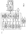
- FIG. 1 is an explanatory diagram of a navigation system 1 that is installed in an automobile according to the first embodiment of the present invention.
- a navigation unit 2 of the navigation system 1 includes a CPU 10, which serves as a predicted distance range defining portion and a search portion, a RAM 11, a ROM 12, in which a route guidance program is stored, and a GPS receiver 14.
- a position detection signal which indicates coordinates such as latitude, longitude, and the like and was received by the GPS receiver 14 from a Global Positioning System (GPS) satellite, is input to the CPU 10, which uses radio navigation to compute an absolute position for a host vehicle.
- GPS Global Positioning System
- a vehicle speed pulse and an angular velocity are input to the CPU 10 from a vehicle speed sensor 40 and a gyroscopic sensor 41, respectively.
- the CPU 10 uses the vehicle speed pulse and the angular velocity to compute, by autonomous navigation, a relative position in relation to a reference position.
- the CPU 10 specifies the host vehicle position by combining the relative position with the absolute position that was computed by radio navigation.
- a communications interface 16 of the navigation unit 2 receives Vehicle Information and Communication System (VICS) signals from radio beacons or optical beacons installed alongside the road or the like, or from FM multiplex broadcasting base stations.
- VICS signals contain road traffic information by city or prefecture, as well as road traffic information that indicates the traffic circumstances within a range of several tens of kilometers to several hundred kilometers in the direction of travel from the current position.
- the navigation unit 2 also includes a geographic data recording portion 17.
- the geographic data recording portion 17 is a built-in hard disk or an external recording medium such as an optical disk or the like.
- Stored in the geographic data recording portion 17 are network data for each route (hereinafter called route data 18), to be used in searching for a route to a destination, and map drawing data 19 for each map that is output to a map screen 25a of a display 25, which serves as an output portion.
- the route data 18 includes a header 18a, which is data for each region into which the entire country is partitioned, node data 18b, which contains node numbers and the like indicating intersections and end points of roads, link data 18c, which contains identifiers and the like for links between the nodes, a link cost 18d, coordinate data 18e, which indicates the coordinates of nodes and links, a version 18f, and the like.
- the header 18a contains a mesh number or the like to identify each region into which the entire country is partitioned.
- the link data 18c include data on link identifiers, connecting nodes, through-travel restrictions, and the like.
- the link cost 18d is a fixed value, data based on the link length and road width for each link.
- the CPU 10 uses the route data 18 to search for a recommended route from the current host vehicle position to the destination, such as a route that will shorten the travel time, an easy-to-drive route, or the like.
- the map drawing data 19 are stored for each mesh (parcel) into which a map of the entire country is divided and are divided into different levels, from wide-area maps to local-area maps.
- the map drawing data 19 include a header 19a, road data 19b, background data 19c, and the like.
- the header 19a includes the mesh number, the level of the data, and the like.
- the road data 19b are data that are displayed on the map and include data that indicate the shape of the road, such as shape compensation data, road width data, and the like.
- the background data 19c are drawing data that depict roads, urban areas, rivers, and the like.
- the navigation unit 2 includes an image processor 20 (refer to FIG. 1 ), which, based on instructions from the CPU 10, reads the map drawing data 19 from the geographic data recording portion 17 in order to draw a map of the area surrounding the host vehicle position.
- the image processor 20 creates output data and stores it temporarily in an image memory 21. Based on the output data, the image processor 20 outputs an image signal to the display 25, displaying an image on the map display screen 25a.
- the image processor 20 superimposes a marker 25b on the map display screen 25a to indicate the host vehicle position.
- an operation switch 23 is installed adjacent to the display 25.
- an external input interface 22 that is provided in the navigation unit 2 outputs a signal to the CPU 10 according to an input operation of the operation switch 23.
- a voice processor 24 of the navigation unit 2 under the control of the CPU10, reads a voice file from a voice file data base not shown in FIG. 1 .
- the voice processor 24 also outputs voice signals and the like to a speaker 26 to provide route guidance.
- the navigation unit 2 also includes a slice width data base 30 and a traffic data base 35.
- the slice width data base 30 serves as a predicted distance range data storage portion in which slice width data 31 are stored as predicted distance range data.
- the traffic data base 35 serves as a traffic data storage portion in which traffic data 36 are stored.
- FIG. 3 is an explanatory diagram of the data structure for the slice width data 31.
- the slice width data 31 is made up of a map mesh (hereinafter called a mesh) ID 31a, a season 31b, a day 31c, and slice widths 31d that serve as distance ranges.
- the mesh ID 31a is an identifier that is assigned to each of the rectangular meshes, measuring 10 kilometers by 10 kilometers, into which the entire country is divided.
- the next level of data down from the mesh ID is the season 31b.
- the season 31b is used to divide the slice width data 31 into data for the spring, summer, autumn, winter, and consecutive holidays.
- the next level of data is the day 31c, made up of the days of the week, plus a holiday.
- the slice widths 31d are stored for each mesh and are data on the distance range that an automobile is predicted to be able to drive in 15 minutes as a prescribed time interval, with 24 hours' worth of data stored in 15-minute units.
- each slice width 31d is prediction data into which the mesh ID 31a (region), the season 31b, the day 31c, and the time of day have been factored.
- the slice widths 31d are statistically processed data based on VICS signals and probe information collected by a control center from individual automobiles.
- the average vehicle speed on all the links within the mesh is computed, and the average vehicle speed is multiplied by a prescribed time interval (15 minutes) to compute the distance that serves as the slice width 31d for the mesh.
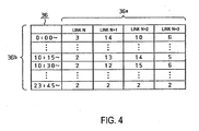
- FIG. 4 is an explanatory diagram of the data structure for the traffic data 36.
- the traffic data 36 is created for each mesh ID 31a, for example, and includes a link cost 36c for a link ID 36a of each link for each time period 36b.
- the time periods 36b are set as 15-minute units, partitioned in the same manner as the time periods that are set for the slice width data 31 (for example, a period from 0:00 to 0:14).
- the link cost 36c is data indicating the average time required to pass through the link during the time period 36b, such as 3 minutes, for example.
- the link cost 18d in the route data 18 is based on the length of the link, the road width, and the like, but does not take the time period 36b into account.
- the link cost 36c in the traffic data 36 is a cost that reflects the traffic conditions in the particular time period 36b.
- the link cost 36c is added to the link cost 18d in the route data 18 and otherwise manipulated to create a new link cost LC.
- the CPU 10 waits for a destination to be set, such as by an operation of a touch panel, the operation switch 23, or the like, in accordance with the route guidance program that is stored in the ROM 12 (step S1-1).
- a destination such as by an operation of a touch panel, the operation switch 23, or the like
- the CPU 10 temporarily stores the coordinates and the like for the destination in the RAM 11.
- the CPU 10 computes the current position of the vehicle by using both radio navigation and autonomous navigation. Based on the map drawing data 19 and the like, the CPU 10 locates the mesh that contains the host vehicle position and obtains the mesh ID 31a (step S1-2). Next, the CPU 10 obtains the current date and the current time from a built-in clock (not shown in FIG. 1 ) in the navigation unit 2 and specifies the factors of the current season 31b, the day 31c, and the time period (step S1-3). Once the factors of the mesh ID 31a, the current season 31b, the day 31c, and the time period are specified, the CPU 10 reads the slice width data 31 and, based on the slice width data 31, selects a temporal sequence of four slice widths 31d (step S1-4).
- the CPU 10 will read the slice width data 31d for the time period 10:15 to 10:29 from among the slice width data 31 shown in FIG. 3 .
- the slice width 31d is 6.0 kilometers, it indicates that in the current mesh, the distance range that a vehicle can travel in 15 minutes is approximately 6 kilometers.
- the CPU 10 reads the slice width 31d for the time period 10:30 to 10:44 as a second slice width 31d for the same mesh 31a, the season 31b, and the day 31c.
- the slice width 31d that is read at this time is data that indicates the distance range that the vehicle can travel during the time period 10:30 to 10:44, starting from the position to which the vehicle advances during the time period 10:15 to 10:29.
- the slice width 31d may be 5.6 kilometers, for example.
- the CPU 10 also reads the slice widths 31d for the time periods 10:45 to 10:59 and 11:00 to 11:14 as third and fourth slice widths 31d for the same mesh ID 31a, the season 31b, and the day 31c, the slice widths 31d being 6.3 kilometers and 5.8 kilometers, respectively. In this manner, the CPU 10 obtains the slice widths 31d that predict the distances that the vehicle will advance within the four consecutive time periods of 10:15 to 10:29, 10:30 to 10:44, 10:45 to 10:59, and 11:00 to 11:14.
- the CPU 10 corrects the first slice width 31d (step S1-5).
- the first slice width 31d predicts the distance that the vehicle will travel during the 15 minutes from 10:15 to 10:29. Therefore, if the current time is 10:20, for example, the CPU 10 re-computes the slice width 31d according to the time remaining until the end of the current time period, which ends at 10:29. (The time from 10:20 to 10:29 is 10 minutes.) In other words, if the predicted travel distance for 15 minutes is 6.0 kilometers, the distance for 10 minutes will be 4.0 kilometers, so the CPU 10 corrects the first slice width 31d to 4.0 kilometers and stores the corrected slice width 31d in the RAM 11.
- the CPU 10 uses the four slice widths 31d to define a circular area for each predicted distance range (step S1-6).
- the CPU 10 uses the first slice width 31d that is stored in the RAM 11 to define a first circular area 51, with its center at the current host vehicle position 50.
- the corrected first slice width 31d is 4.0 kilometers, so the first circular area 51 forms a circle with a radius of 4.0 kilometers around the host vehicle position 50.
- the predicted distance range that the vehicle will travel within the time period from 10:20 to 10:29 lies within the first circular area 51.
- the CPU 10 defines a second circular area 52, which surrounds the first circular area 51 and whose circumference is separated from the circumference of the first circular area 51 by the distance in the second slice width 31d (5.6 kilometers).
- the second circular area 52 is the predicted distance range that the vehicle will travel within the time period from 10:30 to 10:44.
- the CPU 10 also uses the third and fourth slice widths 31d to define a third circular area 53 and a fourth circular area 54, respectively.
- the third circular area 53 surrounds the second circular area 52 and its circumference is separated from the circumference of the second circular area 52 by the distance in the third slice width 31d (6.3 kilometers).
- the fourth circular area 54 surrounds the third circular area 53 and its circumference is separated from the circumference of the third circular area 53 by the distance in the fourth slice width 31d (5.8 kilometers).
- the third circular area 53 is the predicted distance range that the vehicle will travel within the time period from 10:45 to 10:59.
- the fourth circular area 54 is the predicted distance range that the vehicle will travel within the time period from 11:00 to 11:14.
- the first to fourth circular areas 51 to 54 are defined concentrically around the current host vehicle position 50.
- the CPU 10 searches for traffic data 36 in the traffic data base 35, based on the time periods that correspond to the first to fourth circular areas 51 to 54 (step S1-7).
- the CPU 10 searches for the traffic data 36 that corresponds to the mesh ID of the mesh that contains the current host vehicle position 50.
- the CPU 10 locates the corresponding traffic data 36, it first reads the link costs 36c that correspond to the links within the first circular area 51.
- the first circular area 51 is the predicted distance range that the vehicle can travel in the time period from 10:20 to 10:29, so the CPU 10 finds the link costs 36c that correspond to the time period 36b from 10:20 to 10:29.
- the CPU 10 also locates the traffic data 36 that corresponds to the links within the second circular area 52 and then reads the link costs 36c in the traffic data 36. As shown in FIG. 6 , several different meshes are contained within the second circular area 52, so the CPU 10 searches for traffic data 36 for each mesh. From each set of traffic data 36, the CPU 10 reads the link costs 36c for the time period from 10:30 to 10:44, and from among those link costs 36c, the CPU 10 reads the link costs 36c for the links that are contained within the second circular area 52.
- the CPU 10 reads the link costs 36c in the traffic data 36 for the time periods from 10:45 to 10:59 and from 11:00 to 11:14 for each mesh within the third and fourth circular areas 53 and 54, respectively.
- the CPU 10 uses the link costs 36c that it has read, and the link costs 18d in the route data 18 that correspond to the same links to which the link costs 36c correspond, to compute the new link costs LC (step S1-8). For example, the CPU 10 creates the link costs LC by adding or otherwise manipulating the link costs 18d and the link costs 36c, then stores the link costs LC temporarily in the RAM 11.
- the CPU 10 uses the link costs LC to search for a route from the current host vehicle position to the destination coordinates that are stored in the RAM 11 (step S1-9).
- the CPU 10 uses the route data 18 at a level that includes narrow roads, both within the first to fourth circular areas 51 to 54 and within a destination-surrounding region 58 (for example, a square measuring 30 kilometers by 30 kilometers).
- the CPU 10 uses the route data 18 at a higher level, a level that includes main roads such as national highways and the like.
- the CPU 10 uses only the link costs 18d in the route data 18 in searching for a recommended route within the destination-surrounding region 58 and between the first to fourth circular areas 51 to 54 and the destination-surrounding region 58.
- the CPU 10 can detect a congestion-predicted road 56, where congestion is predicted to occur naturally, due to a rush hour or the like, at the time when the vehicle passes through (for example, 11:00 to 11:14), even though congestion is not occurring there at the current time (10:20). The CPU 10 can thus search for a route that avoids the congestion-predicted road 56.
- the CPU 10 can determine that the link cost LC for the congestion-predicted road 56 is high and can therefore compute the first route R1 as the recommended route, because it avoids the congestion-predicted road 56.
- the CPU 10 can determine that the link cost LC is low for the first route R1, which includes the currently congested road 57, and therefore select the first route R1, where congestion is currently occurring but is predicted to end by the time the vehicle passes through, instead of selecting a second route R2, where congestion is not occurring, but which would take more time than the first route R1.
- the CPU 10 computes the time required to reach the destination and stores it temporarily in the RAM 11.
- the CPU 10 executes route guidance by displaying the recommended route on the display 25 (step S1-10).
- the CPU 10 outputs to the image processor 20 data such as links and the like that indicate the recommended route.
- the image processor 20 reads the map drawing data 19 and creates output data that include the recommended route from the current host vehicle position 50 to the destination.
- the output data are stored temporarily in the image memory 21 and are output to the display 25 as image signals.
- a guidance screen 60 is displayed on the display 25, as shown in FIG. 9A .
- a host vehicle position marker 62, a destination marker 63, and a recommended route 64 that connects the markers 62 and 63 are superimposed on a map image 61, which is a map from the host vehicle position 50 to the destination.
- voice guidance for the route may also be output from the speaker by the voice processor 24.
- a congestion prediction marker 65 may be displayed on the map image 61 to indicate a road where congestion is predicted at the time when the vehicle will pass through.
- the CPU 10 determines whether or not the vehicle is still within the fourth circular area 54 (step S1-11). If the CPU 10 determines that the vehicle is still within the fourth circular area 54 (YES at step S1-11), the CPU 10 determines whether or not the guidance is finished (step S1-12). In the first embodiment, the CPU 10 determines whether or not the vehicle has arrived at the destination, or whether or not a route guidance interruption operation has been executed by the operation switch 23 or a touch panel. If the CPU 10 determines that the guidance is not finished (NO at step S1-12), it returns to step S1-10 and continues the route guidance.
- the CPU 10 determines that the vehicle is no longer within the fourth circular area 54 (NO at step S1-11), it returns to step 1-2, where it locates the mesh that contains the current host vehicle position and repeats the processing described above.
- the CPU 10 predicts the traffic circumstances at the time the vehicle will pass through, searches for a route, and executes guidance for the recommended route.
- the CPU 10 determines that the guidance is finished (YES at step S1-12) and ends the guidance.
- a second embodiment of the present invention will be explained below according to FIGS. 10 to 14 .
- the configuration of the second embodiment differs from that of the first embodiment only in that a method for creating the slice width data 31 and a method for distributing the data are added, so only those differences will be explained, and all other explanations shall be omitted.
- a data statistics system 70 which serves as a route guidance system, has a statistical server 71, which serves as a statistical processing server that does statistical processing of VICS signals and probe information.
- the statistical server 71 is connected such that it can receive various types of data from a beacon 72 or a base station 73 and is also connected such that it can both send and receive data to and from navigation systems 1 that are installed in automobiles C.
- the statistical server 71 receives probe data Pr as probe information and VICS signals Vc as road traffic information from each navigation system 1, from the beacon 72, and from a traffic management server, which is not shown in FIG. 10 .
- the probe data Pr include data on the position, speed, and operating characteristics of the automobile C, as well as the time.
- the statistical server 71 includes a CPU 75, which serves as a first statistical processing portion and a second statistical processing portion, a RAM 76, a ROM 77, a communications interface 78, a slice width data base 80, which serves as a storage portion for predicted distance range data, and a traffic data base 81, which serves as a storage portion for traffic data.
- the CPU 75 inputs the probe data Pr from the navigation systems 1 via the communications interface 78 and statistically processes the probe data Pr according to a statistical processing program that is stored in the ROM 77.
- the CPU 75 also receives the VICS data Vc from the traffic management server, which is not shown in FIG. 10 , or from the beacon 72 and statistically processes the VICS data Vc.
- slice width data 82 for the entire country are stored in the slice width data base 80 as predicted distance range data
- traffic data 83 are stored in the traffic data base 81.
- the CPU 75 in the statistical server 71 defines meshes that determine the slice widths (step S2-1).
- the CPU 75 then defines the slice width factors (step S2-2).
- the factors are the season and the day, so the CPU 75 determines the factors for computing slice widths, such as Mondays in spring or the like.
- the CPU 75 defines the time periods that will determine the slice widths (step S2-3). The time periods are divided into 15-minute intervals in the same manner as in the slice widths 31d in the first embodiment.
- the CPU 75 defines the slice widths (step S2-4). For example, based on the probe data Pr and the VICS data Vc, the CPU 75 statistically processes distance ranges that vehicles drive during the time period from 10:15 to 10:29. Based on the resulting statistically processed slice widths, slice width graphs 85a and 85b in FIGS. 13 and 14 are obtained.
- the graph 85a shown in FIG. 13 is a graph that shows slice widths for Mondays in spring. It shows that except for the noon hour, the slice widths are lower as one progresses from the morning to the afternoon, and at night the slice widths gradually increase.
- the graph 85b shown in FIG. 14 is a graph for a different region (mesh) from that described by the graph 85a in FIG. 13 . Except for the region, the factors for the graph 85b are same as those for the graph 85a in FIG. 13 , but the slice width decreases only during the morning and evening rush hours, with little change other than at those times. It can thus be seen that the distance that the vehicle travels within a specified time period varies significantly according to the region (mesh), time period, and the like. Therefore, the statistical server 71 defines a slice width for each factor and includes those slice widths in the slice width data 82 it creates.
- the CPU 75 determines whether or not the slice widths have been determined for all of the time periods (step S2-5). If the slice widths have not been determined for all of the time periods (NO at step S2-5), the process returns to step S2-3 and does the statistical processing of the slice widths for the next time period. If the slice widths have been determined for all of the time periods in one day in one season in one mesh (YES at step S2-5), the process proceeds to step S2-6.
- step S2-6) determines whether or not the slice widths have been determined for all of the seasons, days, and the like. If the slice widths have not been determined for all of the factors (NO at step S2-6), the process returns to step S2-2 and does the statistical processing of the slice widths for the next season or day. If all of the slice widths have been determined for one mesh (YES at step S2-6), the process proceeds to step S2-7.
- the CPU 75 determines whether or not the slice widths have been determined for all of the meshes. If the slice widths have not been determined for all of the meshes (NO at step S2-7), the process returns to step S2-1 and does the statistical processing of the slice widths for the next mesh. If the slice widths have been determined for all of the meshes (YES at step S2-7), the process ends.
- the CPU 75 does statistical processing of the probe data Pr and the VICS data Vc in the same manner, computing link costs for each time period and creating the traffic data base 81.
- the link costs that are created at this time are created on the assumption that they will be recomputed together with the link costs 18d in the route data 18 in the navigation system 1.
- the statistical server 71 transmits the slice width data 82 and the traffic data 83 to each navigation system 1 over network N.
- the navigation system 1 receives the transmitted slice width data 82 and traffic data 83 and stores them the slice width data base 30 and the traffic data base 35 in the navigation system 1.
- the slice width data 31 and the traffic data 36 in the navigation system 1 can be successively updated.
- a navigation system uses a slice width data base that stores slice width data in which distance ranges where a vehicle will be within specified times are predicted for individual zones and individual time periods.
- a navigation system defines ring-shaped circular areas, which are centered around a current host vehicle position, in a temporal sequence that uses the current time as a reference. Also, based on traffic data for individual meshes and individual time periods, the navigation system searches for a recommended route from the current host vehicle position to a destination, using a traffic data base that stores traffic data that is created for individual links and using traffic data for time periods that correspond to individual circular areas in which the links are located.
Description
- The present invention relates to a route search method and a navigation system.
- In recent years, the development of Intelligent Transportation Systems has been promoted in an attempt to achieve smoother automobile driving. One field in which development has been promoted is advanced navigation systems. An example is a navigation system equipped with Vehicle Information and Communication System (VICS) functions. The navigation system receives information from beacons and FM multiplex broadcasts about current traffic congestion conditions, then executes route guidance to avoid congested locations.
- Also, in Japanese Patent Application Publication No.
JP-A-2004-301677 - However, the navigation system described above predicts the arrival time in a given mesh region by determining representative coordinates for a rectangular mesh region, then dividing the straight-line distance from the current position to the representative coordinates by a predetermined speed. Because the arrival times for a plurality of mesh regions are calculated in this manner, it is possible that the volume of processing will become excessive, or that the accuracy of the predicted arrival timers will drop, particularly in corner portions and edge portions of the mesh regions. This in turn raises the possibility that the recommended route will be determined using statistical information for a time period much different from the actual arrival time.
- Also, the navigation system described above predicts the arrival time by dividing the straight-line distance to the representative coordinates by a predetermined speed. Thus the process for predicting the arrival time does not consider such factors as the region, the time period, whether it is a weekday or a holiday, and the like. There is therefore a possibility that the accuracy of the predicted arrival time will be diminished.
- The document
US 2004 034464 A describes a vehicle navigation system for searching a route from a current position of the vehicle to a destination based on traffic data as e.g. congestion area data. A temporal sequence of predicted distance ranges centered at the current host vehicle position is defined using the current time as a reference, based on predicted distance range data in which distance ranges where the vehicle will be within specified times are predicted for individual zones and individual time periods. - In light of the problems described above, it is an object of the present invention to provide a route search method that can accurately search for a recommended route, as well as a route guidance system, a navigation system, and a statistical processing server.
- According to the first aspect of the present invention, the predicted distance ranges for the vehicle are predicted for individual time periods in a temporal sequence. The traffic data that are used within a predicted distance range, which indicates the range where the vehicle will be in a given time period, correspond to that time period. Therefore, when the system searches for the traffic data that correspond to the time period, the time period when the vehicle will be at a given link can be predicted accurately, so the traffic data for the appropriate time period can be used. Factoring in time-related changes in this manner makes it possible to predict roads where congestion will be occurring and roads where congestion will have ended at the time the vehicle passes through.
- According to the second aspect of the present invention, the first statistical processing portion creates predicted distance range data in which the predicted distance ranges for the vehicle are predicted for individual time periods in a temporal sequence, and the second statistical processing portion creates traffic data that indicate the traffic circumstances for individual time periods. Therefore, when the search portion searches for the traffic data that correspond to the time period, the time period when the vehicle will be at a given link can be predicted accurately, so the traffic data for the appropriate time period can be used. Factoring in time-related changes in this manner makes it possible to predict roads where congestion will be occurring and roads where congestion will have ended at the time the vehicle passes through.
- According to the third aspect of the present invention, the predicted distance ranges for the vehicle are predicted for individual time periods in a temporal sequence. The traffic data that are used within a predicted distance range, which indicates the range where the vehicle will be in a given time period, correspond to that time period. Therefore, when the system searches for the traffic data that correspond to the time period, the time period when the vehicle will be at a given link can be predicted accurately, so the traffic data for the appropriate time period can be used. Factoring in time-related changes in this manner makes it possible to predict roads where congestion will be occurring and roads where congestion will have ended at the time the vehicle passes through.
- According to the fourth aspect of the present invention, the predicted distance range data is stored for each map mesh. Therefore, the only data the predicted distance range defining portion needs to read is the predicted distance range data for the map mesh that contains the current position of the vehicle, so the processing load is lighter than, for example, a case where the predicted distance range defining portion has to detect a link within a specified distance from the current position of the vehicle and then sequentially search for the predicted distance range data that correspond to the detected link.
- According to the fifth aspect of the present invention, each predicted distance range is defined as a concentric circular area with the current position of the vehicle at its center, the predicted distance range can be recomputed along with time-related changes.
- According to the sixth aspect of the present invention, the time period for the predicted distance range closest to the current position of the vehicle is synchronized with the current time, and the predicted distance range data are corrected accordingly. It is therefore possible to define the predicted distance range more accurately, so the traffic data for the appropriate time period can be used.
- According to the seventh aspect of the present invention, the predicted distance range data are created for individual zones, seasons, days, holidays, and consecutive holidays. It is therefore possible to compute more accurately the distance range from the current position of the vehicle that the vehicle can travel within a specified time.
- According to the eighth aspect of the present invention, the navigation system receives the predicted distance range data or the traffic data. It is therefore possible to execute route searching using new data that are successively received, so the accuracy of route searching is improved.
- According to the ninth aspect of the present invention, the navigation system has the learning function, which updates the predicted distance range data or the traffic data based on the driving history. It is therefore possible to execute route searching using new data that are successively updated, so the accuracy of route searching is improved.
- According to the tenth aspect of the present invention, the statistical processing server creates the predicted distance range data, in which the distance ranges where the vehicle will be within specified times are predicted based on the road traffic information or the probe information, as well as the traffic data for each time period. It is therefore possible to use this data to factor time-related changes into the predicting of congestion circumstances and traffic volume circumstances.
-
FIG. 1 is a block diagram that explains a configuration of a navigation system according to a first embodiment of the present invention; -
FIG. 2A is an explanatory diagram of a data structure for route data; -
FIG. 2B is an explanatory diagram of a data structure for map drawing data; -
FIG. 3 is an explanatory diagram of a data structure for slice width data; -
FIG. 4 is an explanatory diagram of a data structure for traffic data; -
FIG. 5 is an explanatory diagram of a processing procedure according to the first embodiment of the present invention; -
FIG. 6 is an explanatory diagram of first to fourth circular areas; -
FIG. 7 is an explanatory diagram of route search processing; -
FIG. 8 is an explanatory diagram of route search processing; -
FIG. 9A is an explanatory diagram of a guidance screen; -
FIG. 9B is an explanatory diagram of a guidance screen that shows a road where congestion is predicted; -
FIG. 10 is an explanatory diagram of a data statistics system according to a second embodiment of the present invention; -
FIG. 11 is a block diagram of a statistical server; -
FIG. 12 is an explanatory diagram of a processing procedure according to the second embodiment of the present invention; -
FIG. 13 is an explanatory diagram of statistical results for a slice width in a region A; and -
FIG. 14 is an explanatory diagram of statistical results for a slice width in a region B. - A first embodiment of the present invention will be explained below according to
FIGS. 1 to 9 .FIG. 1 is an explanatory diagram of anavigation system 1 that is installed in an automobile according to the first embodiment of the present invention. - As shown in
FIG. 1 , anavigation unit 2 of thenavigation system 1 includes aCPU 10, which serves as a predicted distance range defining portion and a search portion, aRAM 11, aROM 12, in which a route guidance program is stored, and aGPS receiver 14. A position detection signal, which indicates coordinates such as latitude, longitude, and the like and was received by theGPS receiver 14 from a Global Positioning System (GPS) satellite, is input to theCPU 10, which uses radio navigation to compute an absolute position for a host vehicle. Through avehicle interface 15 included in thenavigation unit 2, a vehicle speed pulse and an angular velocity are input to theCPU 10 from avehicle speed sensor 40 and agyroscopic sensor 41, respectively. TheCPU 10 uses the vehicle speed pulse and the angular velocity to compute, by autonomous navigation, a relative position in relation to a reference position. TheCPU 10 then specifies the host vehicle position by combining the relative position with the absolute position that was computed by radio navigation. - Also, a
communications interface 16 of thenavigation unit 2 receives Vehicle Information and Communication System (VICS) signals from radio beacons or optical beacons installed alongside the road or the like, or from FM multiplex broadcasting base stations. The VICS signals contain road traffic information by city or prefecture, as well as road traffic information that indicates the traffic circumstances within a range of several tens of kilometers to several hundred kilometers in the direction of travel from the current position. - The
navigation unit 2 also includes a geographicdata recording portion 17. The geographicdata recording portion 17 is a built-in hard disk or an external recording medium such as an optical disk or the like. Stored in the geographicdata recording portion 17 are network data for each route (hereinafter called route data 18), to be used in searching for a route to a destination, and map drawingdata 19 for each map that is output to amap screen 25a of adisplay 25, which serves as an output portion. - As shown in
FIG. 2A , theroute data 18 includes aheader 18a, which is data for each region into which the entire country is partitioned,node data 18b, which contains node numbers and the like indicating intersections and end points of roads, linkdata 18c, which contains identifiers and the like for links between the nodes, alink cost 18d, coordinatedata 18e, which indicates the coordinates of nodes and links, a version 18f, and the like. Theheader 18a contains a mesh number or the like to identify each region into which the entire country is partitioned. Thelink data 18c include data on link identifiers, connecting nodes, through-travel restrictions, and the like. Thelink cost 18d is a fixed value, data based on the link length and road width for each link. Employing publicly known methods such as a Dykstra method and the like, theCPU 10 uses theroute data 18 to search for a recommended route from the current host vehicle position to the destination, such as a route that will shorten the travel time, an easy-to-drive route, or the like. - The
map drawing data 19 are stored for each mesh (parcel) into which a map of the entire country is divided and are divided into different levels, from wide-area maps to local-area maps. As shown inFIG. 2B , themap drawing data 19 include aheader 19a,road data 19b,background data 19c, and the like. Theheader 19a includes the mesh number, the level of the data, and the like. Theroad data 19b are data that are displayed on the map and include data that indicate the shape of the road, such as shape compensation data, road width data, and the like. Thebackground data 19c are drawing data that depict roads, urban areas, rivers, and the like. - The
navigation unit 2 includes an image processor 20 (refer toFIG. 1 ), which, based on instructions from theCPU 10, reads themap drawing data 19 from the geographicdata recording portion 17 in order to draw a map of the area surrounding the host vehicle position. Theimage processor 20 creates output data and stores it temporarily in animage memory 21. Based on the output data, theimage processor 20 outputs an image signal to thedisplay 25, displaying an image on themap display screen 25a. Theimage processor 20 superimposes amarker 25b on themap display screen 25a to indicate the host vehicle position. - Also, an
operation switch 23 is installed adjacent to thedisplay 25. When theoperation switch 23 is operated, anexternal input interface 22 that is provided in thenavigation unit 2 outputs a signal to theCPU 10 according to an input operation of theoperation switch 23. - A
voice processor 24 of thenavigation unit 2, under the control of the CPU10, reads a voice file from a voice file data base not shown inFIG. 1 . Thevoice processor 24 also outputs voice signals and the like to aspeaker 26 to provide route guidance. - The
navigation unit 2 also includes a slicewidth data base 30 and atraffic data base 35. The slicewidth data base 30 serves as a predicted distance range data storage portion in which slicewidth data 31 are stored as predicted distance range data. Thetraffic data base 35 serves as a traffic data storage portion in whichtraffic data 36 are stored.FIG. 3 is an explanatory diagram of the data structure for theslice width data 31. Theslice width data 31 is made up of a map mesh (hereinafter called a mesh)ID 31a, aseason 31b, aday 31c, andslice widths 31d that serve as distance ranges. Themesh ID 31a is an identifier that is assigned to each of the rectangular meshes, measuring 10 kilometers by 10 kilometers, into which the entire country is divided. The next level of data down from the mesh ID is theseason 31b. Theseason 31b is used to divide theslice width data 31 into data for the spring, summer, autumn, winter, and consecutive holidays. The next level of data is theday 31c, made up of the days of the week, plus a holiday. - The
slice widths 31d are stored for each mesh and are data on the distance range that an automobile is predicted to be able to drive in 15 minutes as a prescribed time interval, with 24 hours' worth of data stored in 15-minute units. In other words, eachslice width 31d is prediction data into which themesh ID 31a (region), theseason 31b, theday 31c, and the time of day have been factored. In the first embodiment, theslice widths 31d are statistically processed data based on VICS signals and probe information collected by a control center from individual automobiles. For example, based on VICS signals and probe information corresponding to each link within the mesh, the average vehicle speed on all the links within the mesh is computed, and the average vehicle speed is multiplied by a prescribed time interval (15 minutes) to compute the distance that serves as theslice width 31d for the mesh. - Next, the
traffic data 36 will be explained according toFIG. 4. FIG. 4 is an explanatory diagram of the data structure for thetraffic data 36. Thetraffic data 36 is created for eachmesh ID 31a, for example, and includes a link cost 36c for a link ID 36a of each link for eachtime period 36b. Thetime periods 36b are set as 15-minute units, partitioned in the same manner as the time periods that are set for the slice width data 31 (for example, a period from 0:00 to 0:14). The link cost 36c is data indicating the average time required to pass through the link during thetime period 36b, such as 3 minutes, for example. In other words, thelink cost 18d in theroute data 18 is based on the length of the link, the road width, and the like, but does not take thetime period 36b into account. The link cost 36c in thetraffic data 36 is a cost that reflects the traffic conditions in theparticular time period 36b. The link cost 36c is added to thelink cost 18d in theroute data 18 and otherwise manipulated to create a new link cost LC. - Next, the route search processing procedure in the first embodiment will be explained according to
FIG. 5 . First, theCPU 10 waits for a destination to be set, such as by an operation of a touch panel, theoperation switch 23, or the like, in accordance with the route guidance program that is stored in the ROM 12 (step S1-1). When theCPU 10 determines that the destination has been input (YES at step S1-1), theCPU 10 temporarily stores the coordinates and the like for the destination in theRAM 11. - Next, the
CPU 10 computes the current position of the vehicle by using both radio navigation and autonomous navigation. Based on themap drawing data 19 and the like, theCPU 10 locates the mesh that contains the host vehicle position and obtains themesh ID 31a (step S1-2). Next, theCPU 10 obtains the current date and the current time from a built-in clock (not shown inFIG. 1 ) in thenavigation unit 2 and specifies the factors of thecurrent season 31b, theday 31c, and the time period (step S1-3). Once the factors of themesh ID 31a, thecurrent season 31b, theday 31c, and the time period are specified, theCPU 10 reads theslice width data 31 and, based on theslice width data 31, selects a temporal sequence of fourslice widths 31d (step S1-4). - For example, if the
season 31b is spring, theday 31c is Monday, and the time is within the time period 10:15 to 10:29, theCPU 10 will read theslice width data 31d for the time period 10:15 to 10:29 from among theslice width data 31 shown inFIG. 3 . For example, if theslice width 31d is 6.0 kilometers, it indicates that in the current mesh, the distance range that a vehicle can travel in 15 minutes is approximately 6 kilometers. - Next, the
CPU 10 reads theslice width 31d for the time period 10:30 to 10:44 as asecond slice width 31d for thesame mesh 31a, theseason 31b, and theday 31c. Theslice width 31d that is read at this time is data that indicates the distance range that the vehicle can travel during the time period 10:30 to 10:44, starting from the position to which the vehicle advances during the time period 10:15 to 10:29. Theslice width 31d may be 5.6 kilometers, for example. - The
CPU 10 also reads theslice widths 31d for the time periods 10:45 to 10:59 and 11:00 to 11:14 as third andfourth slice widths 31d for thesame mesh ID 31a, theseason 31b, and theday 31c, theslice widths 31d being 6.3 kilometers and 5.8 kilometers, respectively. In this manner, theCPU 10 obtains theslice widths 31d that predict the distances that the vehicle will advance within the four consecutive time periods of 10:15 to 10:29, 10:30 to 10:44, 10:45 to 10:59, and 11:00 to 11:14. - Next, as shown in
FIG. 5 , theCPU 10 corrects thefirst slice width 31d (step S1-5). As described above, thefirst slice width 31d predicts the distance that the vehicle will travel during the 15 minutes from 10:15 to 10:29. Therefore, if the current time is 10:20, for example, theCPU 10 re-computes theslice width 31d according to the time remaining until the end of the current time period, which ends at 10:29. (The time from 10:20 to 10:29 is 10 minutes.) In other words, if the predicted travel distance for 15 minutes is 6.0 kilometers, the distance for 10 minutes will be 4.0 kilometers, so theCPU 10 corrects thefirst slice width 31d to 4.0 kilometers and stores the correctedslice width 31d in theRAM 11. - Next, the
CPU 10, using the fourslice widths 31d, defines a circular area for each predicted distance range (step S1-6). First, as shown inFIG. 6 , theCPU 10 uses thefirst slice width 31d that is stored in theRAM 11 to define a first circular area 51, with its center at the currenthost vehicle position 50. The correctedfirst slice width 31d is 4.0 kilometers, so the first circular area 51 forms a circle with a radius of 4.0 kilometers around thehost vehicle position 50. The predicted distance range that the vehicle will travel within the time period from 10:20 to 10:29 lies within the first circular area 51. - Next, the
CPU 10 defines a second circular area 52, which surrounds the first circular area 51 and whose circumference is separated from the circumference of the first circular area 51 by the distance in thesecond slice width 31d (5.6 kilometers). The second circular area 52 is the predicted distance range that the vehicle will travel within the time period from 10:30 to 10:44. - The
CPU 10 also uses the third andfourth slice widths 31d to define a thirdcircular area 53 and a fourthcircular area 54, respectively. The thirdcircular area 53 surrounds the second circular area 52 and its circumference is separated from the circumference of the second circular area 52 by the distance in thethird slice width 31d (6.3 kilometers). The fourthcircular area 54 surrounds the thirdcircular area 53 and its circumference is separated from the circumference of the thirdcircular area 53 by the distance in thefourth slice width 31d (5.8 kilometers). The thirdcircular area 53 is the predicted distance range that the vehicle will travel within the time period from 10:45 to 10:59. The fourthcircular area 54 is the predicted distance range that the vehicle will travel within the time period from 11:00 to 11:14. Thus the first to fourth circular areas 51 to 54 are defined concentrically around the currenthost vehicle position 50. - Next, as shown in
FIG. 5 , theCPU 10 searches fortraffic data 36 in thetraffic data base 35, based on the time periods that correspond to the first to fourth circular areas 51 to 54 (step S1-7). First, theCPU 10 searches for thetraffic data 36 that corresponds to the mesh ID of the mesh that contains the currenthost vehicle position 50. When theCPU 10 locates the correspondingtraffic data 36, it first reads the link costs 36c that correspond to the links within the first circular area 51. The first circular area 51 is the predicted distance range that the vehicle can travel in the time period from 10:20 to 10:29, so theCPU 10 finds the link costs 36c that correspond to thetime period 36b from 10:20 to 10:29. - The
CPU 10 also locates thetraffic data 36 that corresponds to the links within the second circular area 52 and then reads the link costs 36c in thetraffic data 36. As shown inFIG. 6 , several different meshes are contained within the second circular area 52, so theCPU 10 searches fortraffic data 36 for each mesh. From each set oftraffic data 36, theCPU 10 reads the link costs 36c for the time period from 10:30 to 10:44, and from among those link costs 36c, theCPU 10 reads the link costs 36c for the links that are contained within the second circular area 52. - In the same manner, the
CPU 10 reads the link costs 36c in thetraffic data 36 for the time periods from 10:45 to 10:59 and from 11:00 to 11:14 for each mesh within the third and fourthcircular areas - Next, the
CPU 10 uses the link costs 36c that it has read, and the link costs 18d in theroute data 18 that correspond to the same links to which the link costs 36c correspond, to compute the new link costs LC (step S1-8). For example, theCPU 10 creates the link costs LC by adding or otherwise manipulating the link costs 18d and the link costs 36c, then stores the link costs LC temporarily in theRAM 11. - Once the
CPU 10 has created the link costs LC for the links that are contained within the circular areas 51 to 54, it uses the link costs LC to search for a route from the current host vehicle position to the destination coordinates that are stored in the RAM 11 (step S1-9). At this time, theCPU 10, as shown inFIG. 7 , uses theroute data 18 at a level that includes narrow roads, both within the first to fourth circular areas 51 to 54 and within a destination-surrounding region 58 (for example, a square measuring 30 kilometers by 30 kilometers). Between the first to fourth circular areas 51 to 54 and the destination-surroundingregion 58, theCPU 10 uses theroute data 18 at a higher level, a level that includes main roads such as national highways and the like. Also, because the link costs 36c were read only for the links within the first to fourth circular areas 51 to 54, theCPU 10 uses only the link costs 18d in theroute data 18 in searching for a recommended route within the destination-surroundingregion 58 and between the first to fourth circular areas 51 to 54 and the destination-surroundingregion 58. - Within the first to fourth circular areas 51 to 54, because the
traffic data 36 for approximately 60 minutes ahead is factored into the prediction process at the current point in time, congestion that is not yet occurring, but will occur hereafter, can be predicted. For example, as shown inFIG. 7 , theCPU 10 can detect a congestion-predictedroad 56, where congestion is predicted to occur naturally, due to a rush hour or the like, at the time when the vehicle passes through (for example, 11:00 to 11:14), even though congestion is not occurring there at the current time (10:20). TheCPU 10 can thus search for a route that avoids the congestion-predictedroad 56. For example, in a case where theCPU 10 locates a first route R1 and a second route R2 that connect ahost vehicle position 50 and adestination 55, but the second route R2 contains the congestion-predictedroad 56, theCPU 10 can determine that the link cost LC for the congestion-predictedroad 56 is high and can therefore compute the first route R1 as the recommended route, because it avoids the congestion-predictedroad 56. - Conversely, as shown in
FIG. 8 , even though congestion is occurring at the current time (10:20) on a currently congestedroad 57 on a first route R1 from ahost vehicle position 50 to adestination 55, due to a rush hour or the like, the congestion might be predicted to end by the time when the vehicle passes through (for example, 11:00 to 11:14). In this case, theCPU 10 can determine that the link cost LC is low for the first route R1, which includes the currently congestedroad 57, and therefore select the first route R1, where congestion is currently occurring but is predicted to end by the time the vehicle passes through, instead of selecting a second route R2, where congestion is not occurring, but which would take more time than the first route R1. - Once the recommended route has been determined, the
CPU 10 computes the time required to reach the destination and stores it temporarily in theRAM 11. Next, as shown inFIG. 5 , theCPU 10 executes route guidance by displaying the recommended route on the display 25 (step S1-10). TheCPU 10 outputs to theimage processor 20 data such as links and the like that indicate the recommended route. Based on the data that were input, theimage processor 20 reads themap drawing data 19 and creates output data that include the recommended route from the currenthost vehicle position 50 to the destination. The output data are stored temporarily in theimage memory 21 and are output to thedisplay 25 as image signals. - By this process, a
guidance screen 60 is displayed on thedisplay 25, as shown inFIG. 9A . On theguidance screen 60, a hostvehicle position marker 62, adestination marker 63, and a recommendedroute 64 that connects themarkers map image 61, which is a map from thehost vehicle position 50 to the destination. At this time, voice guidance for the route may also be output from the speaker by thevoice processor 24. Also, depending on a variety of mode settings, acongestion prediction marker 65 may be displayed on themap image 61 to indicate a road where congestion is predicted at the time when the vehicle will pass through. - While executing guidance for the recommended route, the
CPU 10 determines whether or not the vehicle is still within the fourth circular area 54 (step S1-11). If theCPU 10 determines that the vehicle is still within the fourth circular area 54 (YES at step S1-11), theCPU 10 determines whether or not the guidance is finished (step S1-12). In the first embodiment, theCPU 10 determines whether or not the vehicle has arrived at the destination, or whether or not a route guidance interruption operation has been executed by theoperation switch 23 or a touch panel. If theCPU 10 determines that the guidance is not finished (NO at step S1-12), it returns to step S1-10 and continues the route guidance. - On the other hand, if the
CPU 10 determines that the vehicle is no longer within the fourth circular area 54 (NO at step S1-11), it returns to step 1-2, where it locates the mesh that contains the current host vehicle position and repeats the processing described above. TheCPU 10 predicts the traffic circumstances at the time the vehicle will pass through, searches for a route, and executes guidance for the recommended route. - If the vehicle has arrived at the destination, or if a route guidance interruption operation has been executed by a touch panel or the
operation switch 23, theCPU 10 determines that the guidance is finished (YES at step S1-12) and ends the guidance. - According to the first embodiment, the effects described below can be obtained.
- (1) In the first embodiment, the
navigation system 1 stores theslice width data 31, which predict the distance range the vehicle can travel from the current host vehicle position in 15 minutes during various time periods, in the slicewidth data base 30. Thenavigation system 1 also includes thetraffic data base 35, in which are stored the link costs 36c, which are created for each link in each mesh based on the traffic circumstances in each time period. Based on theslice width data 31, theCPU 10 defines the first to fourth circular areas 51 to 54 concentrically around the current host vehicle position in a temporal sequence using the current time as a reference. TheCPU 10 also searches for the recommended route from the current host vehicle position to the destination using the link costs 36c for the links in the first to fourth circular areas 51 to 54 and for the time periods that correspond to the first to fourth circular areas 51 to 54. Because theCPU 10 can use theslice width data 31 to predict the time periods in which the vehicle will traverse those links, it can use thetraffic data 36 for the appropriate time periods. Therefore, even though the traffic volume and congestion level vary on almost all roads according to the time period, the roads where congestion will naturally occur can be predicted in advance by factoring those time-related variations into the predictions. A route can therefore be recommended to avoid congestion that will occur at the time the vehicle passes through. A recommended route can also be specified where congestion will have ended by the time the vehicle passes through, even if congestion is occurring at the current time. - (2) In the first embodiment, the
CPU 10 of thenavigation system 1 synchronizes the time period for the first circular area 51 with the current time and corrects theslice width 31d accordingly by shortening it. Because the first circular area 51 can therefore be defined more accurately, the accuracy of the second to fourth circular areas 52 to 54 can be improved. - (3) In the first embodiment, the
slice width data 31 has aslice width 31d for each combination of the factors of themesh ID 31a, theseason 31b, theday 31c, and the time period. Regional factors, seasonal factors, and time period factors can therefore be incorporated into theslice widths 31d, so the accuracy of theslice widths 31d can be improved. - A second embodiment of the present invention will be explained below according to
FIGS. 10 to 14 . Note that the configuration of the second embodiment differs from that of the first embodiment only in that a method for creating theslice width data 31 and a method for distributing the data are added, so only those differences will be explained, and all other explanations shall be omitted. - As shown in
FIG. 10 , adata statistics system 70, which serves as a route guidance system, has astatistical server 71, which serves as a statistical processing server that does statistical processing of VICS signals and probe information. Thestatistical server 71 is connected such that it can receive various types of data from abeacon 72 or abase station 73 and is also connected such that it can both send and receive data to and fromnavigation systems 1 that are installed in automobiles C. Over a network N, thestatistical server 71 receives probe data Pr as probe information and VICS signals Vc as road traffic information from eachnavigation system 1, from thebeacon 72, and from a traffic management server, which is not shown inFIG. 10 . The probe data Pr include data on the position, speed, and operating characteristics of the automobile C, as well as the time. - As shown in
FIG. 11 , thestatistical server 71 includes aCPU 75, which serves as a first statistical processing portion and a second statistical processing portion, aRAM 76, aROM 77, acommunications interface 78, a slicewidth data base 80, which serves as a storage portion for predicted distance range data, and atraffic data base 81, which serves as a storage portion for traffic data. TheCPU 75 inputs the probe data Pr from thenavigation systems 1 via thecommunications interface 78 and statistically processes the probe data Pr according to a statistical processing program that is stored in theROM 77. TheCPU 75 also receives the VICS data Vc from the traffic management server, which is not shown inFIG. 10 , or from thebeacon 72 and statistically processes the VICS data Vc. Also,slice width data 82 for the entire country are stored in the slicewidth data base 80 as predicted distance range data, andtraffic data 83 are stored in thetraffic data base 81. - Next, the processing by the
statistical server 71 will be explained according toFIG. 12 . First, theCPU 75 in thestatistical server 71, following the statistical processing program that is stored in theROM 77, defines meshes that determine the slice widths (step S2-1). TheCPU 75 then defines the slice width factors (step S2-2). In the second embodiment, the factors are the season and the day, so theCPU 75 determines the factors for computing slice widths, such as Mondays in spring or the like. Next, theCPU 75 defines the time periods that will determine the slice widths (step S2-3). The time periods are divided into 15-minute intervals in the same manner as in theslice widths 31d in the first embodiment. - Once each of the factors is defined, the
CPU 75 defines the slice widths (step S2-4). For example, based on the probe data Pr and the VICS data Vc, theCPU 75 statistically processes distance ranges that vehicles drive during the time period from 10:15 to 10:29. Based on the resulting statistically processed slice widths,slice width graphs FIGS. 13 and14 are obtained. Thegraph 85a shown inFIG. 13 is a graph that shows slice widths for Mondays in spring. It shows that except for the noon hour, the slice widths are lower as one progresses from the morning to the afternoon, and at night the slice widths gradually increase. - The
graph 85b shown inFIG. 14 is a graph for a different region (mesh) from that described by thegraph 85a inFIG. 13 . Except for the region, the factors for thegraph 85b are same as those for thegraph 85a inFIG. 13 , but the slice width decreases only during the morning and evening rush hours, with little change other than at those times. It can thus be seen that the distance that the vehicle travels within a specified time period varies significantly according to the region (mesh), time period, and the like. Therefore, thestatistical server 71 defines a slice width for each factor and includes those slice widths in theslice width data 82 it creates. - Once the slice widths are defined, the
CPU 75 determines whether or not the slice widths have been determined for all of the time periods (step S2-5). If the slice widths have not been determined for all of the time periods (NO at step S2-5), the process returns to step S2-3 and does the statistical processing of the slice widths for the next time period. If the slice widths have been determined for all of the time periods in one day in one season in one mesh (YES at step S2-5), the process proceeds to step S2-6. - Next, the
CPU 75 determines whether or not the slice widths have been determined for all of the seasons, days, and the like (step S2-6). If the slice widths have not been determined for all of the factors (NO at step S2-6), the process returns to step S2-2 and does the statistical processing of the slice widths for the next season or day. If all of the slice widths have been determined for one mesh (YES at step S2-6), the process proceeds to step S2-7. - At step S2-7, the
CPU 75 determines whether or not the slice widths have been determined for all of the meshes. If the slice widths have not been determined for all of the meshes (NO at step S2-7), the process returns to step S2-1 and does the statistical processing of the slice widths for the next mesh. If the slice widths have been determined for all of the meshes (YES at step S2-7), the process ends. - The
CPU 75 does statistical processing of the probe data Pr and the VICS data Vc in the same manner, computing link costs for each time period and creating thetraffic data base 81. The link costs that are created at this time are created on the assumption that they will be recomputed together with the link costs 18d in theroute data 18 in thenavigation system 1. Once the slicewidth data base 80 and thetraffic data base 81 are created, thestatistical server 71 transmits theslice width data 82 and thetraffic data 83 to eachnavigation system 1 over network N. Through thecommunications interface 16, which serves as a receiving portion, thenavigation system 1 receives the transmittedslice width data 82 andtraffic data 83 and stores them the slicewidth data base 30 and thetraffic data base 35 in thenavigation system 1. Thus theslice width data 31 and thetraffic data 36 in thenavigation system 1 can be successively updated. - According to the second embodiment, the effect described below can be obtained, in addition to the effects described for the first embodiment.
- (4) In the second embodiment, the
statistical server 71 computes slice widths for each factor, based on the probe data Pr and the like collected from the automobiles C, and creates thetraffic data 83. Thestatistical server 71 also transmits theslice width data 82 and thetraffic data 83 to thenavigation system 1. Thenavigation system 1 can therefore successively update theslice width data 31 and thetraffic data 36, so route searching can be carried out using the newslice width data 82 andtraffic data 83. - Note that in the embodiments described above, the changes described below may be made.
- In the embodiments described above, the first to fourth circular areas 51 to 54 were defined, but only one circular area or a plurality of circular areas other than four may also be defined.
- In the first embodiment, when route searching is carried out, the system uses the
slice width data 31 to search for the recommended route within the first to fourth circular areas 51 to 54, which are centered on the host vehicle position (departure point), and uses theroute data 18 to search for the recommended route outside the first to fourth circular areas 51 to 54. However, theslice width data 31 may be used to search for the entire route to the destination. Also, the predicted travel time to the destination and the actual travel time may be compared en route, and if a large discrepancy is found, searching for the recommended route, as described above, may be carried out again using theslice width data 31 and thetraffic data 36, depending on the circumstances. - In the first embodiment, the example of the destination-surrounding
region 58 is a square measuring 30 kilometers by 30 kilometers, but the destination-surroundingregion 58 may be a circle, an ellipse, an irregular circle, or a polygon. - In the first embodiment, if the
slice width 31d obtained from theslice width data 31 is an indeterminate value such as null or the like, route searching may be executed using only theroute data 18, without using theslice width data 31. - In the first embodiment, the
slice width data 31 may be used even if the vehicle is traveling on an expressway. The system may also search for a route for the vehicle to follow after it leaves the expressway, based the VICS signals and theslice width data 31. - In the second embodiment, the slice widths are created by the
statistical server 71 through statistical processing of the probe data Pr and the like. Another method that the system may use is to use theRAM 11 as a driving history storage portion for storing a driving history for the roads on which the vehicle equipped with thenavigation system 1 has traveled, including the required travel times, time of day, speed, and the like. TheCPU 10 may also serve as a driving learning portion, a first statistical processing portion, and a second statistical processing portion of thenavigation system 1 and create or update theslice width data 31 and thetraffic data 36 based on the driving history. - In the second embodiment, the
navigation system 1 transmits the probe data Pr to thestatistical server 71, but thestatistical server 71 may also do statistical processing of the probe data Pr that is transmitted from an on-board system other than thenavigation system 1. - In the embodiments described above, the server that does the statistical processing of the probe data Pr and the like and the server that transmits the
slice width data 82 and thetraffic data 83 may be separate servers. - In each of the embodiments described above, the first to fourth circular areas 51 to 54 are defined as circular, but they need not be perfect circles and may be ellipses or irregular circles with protruding portions. For example, if the number of lanes or the like on one road is much greater than on other roads in its vicinity, an irregularly circular area may be defined with a protruding portion that corresponds to that road, or an elliptical area may be defined in which the road in question corresponds to the long axis of the ellipse.
- In each of the embodiments described above, the first to fourth circular areas 51 to 54 are defined as circular using the
slice widths 31d for the mesh that contains the host vehicle position, but an area may also be defined as a predicted distance ranges using theslice widths 31d for a mesh that is positioned on the perimeter of a defined area. To explain in greater detail, first the area closest to the host vehicle position (a first area) is defined using theslice widths 31d for the mesh that contains the host vehicle position. Next, if the perimeter of the first area is positioned in a different mesh from the mesh that contains the host vehicle position, theslice widths 31d for the mesh on the perimeter of the first area are used to define the next area (a second area). - Using a slice width data base that stores slice width data in which distance ranges where a vehicle will be within specified times are predicted for individual zones and individual time periods, a navigation system defines ring-shaped circular areas, which are centered around a current host vehicle position, in a temporal sequence that uses the current time as a reference. Also, based on traffic data for individual meshes and individual time periods, the navigation system searches for a recommended route from the current host vehicle position to a destination, using a traffic data base that stores traffic data that is created for individual links and using traffic data for time periods that correspond to individual circular areas in which the links are located.
Claims (8)
- A navigation system (1) that is installed in a vehicle, comprising:a predicted distance range data storage portion (30) that is adapated to store predicted distance range data in which distance ranges where a vehicle will be within a specified time are predicted for individual zones and individual time periods;a predicted distance range defining portion (10) that is adapated to define, based on the predicted distance range data and using a current time as a reference, a temporal sequence of predicted distance ranges (51..54) centered at a current position (50) of the vehicle;a traffic data storage portion (35) that is adapated to store traffic data that is created based on traffic circumstances in individual links and individual time periods; anda search portion (10) that is adapated to searche for a recommended route from the current position of the vehicle to a destination (55) among links within each of the defined predicted distance ranges, using the traffic data for the time periods that correspond to the predicted distance ranges.
- The navigation system according to claim 1, wherein
the predicted distance range data storage portion (30) is adapated to store the predicted distance range data for each map mesh; and
the predicted distance range defining portion (10) is adapted to define the predicted distance ranges by detecting the map mesh that contains the current position of the vehicle and reading the predicted distance range data that correspond to the detected map mesh. - The navigation system according to any one of claims 1 or 2, wherein
the predicted distance range defining portion (10) is adapted to define the predicted distance ranges as concentric circular areas centered at the current position of the vehicle. - The navigation system according to any one of claims 1 to 3, wherein
the predicted distance range defining portion (10) is adapted to synchronize the time period for the predicted distance range closest to the current position of the vehicle with the current time and corrects the predicted distance range accordingly. - The navigation system according to any one of claims 1 to 4, wherein
the predicted distance range data are created for individual zones, seasons, days, holidays, and consecutive holidays. - The navigation system according to any one of claims 1 to 5, further comprising:a receiving portion (16) that is adapted to receive, from outside the system, the predicted distance range data or the traffic data that is based on the traffic circumstances for individual time periods.
- The navigation system according to any one of claims 1 to 6, further comprising:a driving history storage portion (11) that is adapted to store a driving history for a road on which the vehicle has traveled, including a required travel time, a time period, and a speed; anda driving learning portion (10) that is adapted to create or updates the predicted distance range data or the traffic data based on the driving history.
- A route search method that searches for a route from a current position (50) of a vehicle to a destination (55), wherein
a temporal sequence of predicted distance ranges centered at the current position of the vehicle is defined (S1-6) using the current time as a reference, based on predicted distance range data in which distance ranges where a vehicle will be within specified times are predicted for individual zones and individual time periods; and
a recommended route from the current position of the vehicle to the destination is searched (S1-9) using traffic data for time periods that correspond to the predicted distance ranges, the traffic data being among traffic data that is created based on the traffic circumstances for various links and various time periods.
Applications Claiming Priority (1)
| Application Number | Priority Date | Filing Date | Title |
|---|---|---|---|
| JP2006040753A JP4682865B2 (en) | 2006-02-17 | 2006-02-17 | Route search system, route guidance method in route guidance system, and navigation apparatus |
Publications (2)
| Publication Number | Publication Date |
|---|---|
| EP1821069A1 EP1821069A1 (en) | 2007-08-22 |
| EP1821069B1 true EP1821069B1 (en) | 2013-04-24 |
Family
ID=38009498
Family Applications (1)
| Application Number | Title | Priority Date | Filing Date |
|---|---|---|---|
| EP07102485.5A Not-in-force EP1821069B1 (en) | 2006-02-17 | 2007-02-15 | Route search method and route navigation system |
Country Status (5)
| Country | Link |
|---|---|
| US (1) | US8086403B2 (en) |
| EP (1) | EP1821069B1 (en) |
| JP (1) | JP4682865B2 (en) |
| KR (1) | KR101297909B1 (en) |
| CN (1) | CN101025366B (en) |
Families Citing this family (33)
| Publication number | Priority date | Publication date | Assignee | Title |
|---|---|---|---|---|
| JP4228011B2 (en) | 2006-10-03 | 2009-02-25 | トヨタ自動車株式会社 | Navigation device |
| KR20080097321A (en) * | 2007-05-01 | 2008-11-05 | 엘지전자 주식회사 | Method of selecting a route and terminal thereof |
| JP4335935B2 (en) * | 2007-07-05 | 2009-09-30 | 本田技研工業株式会社 | Navigation server, navigation system |
| US9109909B2 (en) | 2009-07-09 | 2015-08-18 | Tomtom International B.V. | Navigation devices |
| CN102483333B (en) * | 2009-07-09 | 2016-03-09 | 通腾科技股份有限公司 | Use the guider with the map datum of route search acceleration data |
| JP6118246B2 (en) | 2010-04-21 | 2017-04-19 | トムトム インターナショナル ベスローテン フエンノートシャップ | System and method for generating a route over an electronic map |
| JP6030544B2 (en) | 2010-04-23 | 2016-11-24 | トムトム インターナショナル ベスローテン フエンノートシャップ | Computer device, method thereof, storage medium, and navigation apparatus |
| JP5325923B2 (en) * | 2011-03-31 | 2013-10-23 | 株式会社ゼンリンデータコム | Mobile area search system and mobile area search method |
| US8990005B2 (en) * | 2011-04-22 | 2015-03-24 | Bayerische Motoren Werke Aktiengesellschaft | System and method for providing georeferenced predictive information to motor vehicles |
| CN102829794A (en) * | 2011-06-13 | 2012-12-19 | 英华达(南京)科技有限公司 | Navigation system and its path designing method |
| DE102011081148A1 (en) * | 2011-08-17 | 2013-02-21 | Bayerische Motoren Werke Aktiengesellschaft | Method for operating navigation unit for motor vehicle, involves determining mean velocity depending on promptly detected course of velocity of motor vehicle |
| CN102607584A (en) * | 2012-03-19 | 2012-07-25 | 中国联合网络通信集团有限公司 | Driving route navigation method, equipment and system |
| JP5605918B2 (en) * | 2012-03-29 | 2014-10-15 | 株式会社デンソーアイティーラボラトリ | Traffic data prediction apparatus, traffic data prediction method, and computer program |
| US9726510B2 (en) * | 2012-10-25 | 2017-08-08 | Intel Corporation | Route optimization including points of interest |
| WO2014080480A1 (en) * | 2012-11-21 | 2014-05-30 | パイオニア株式会社 | Display device, control method, program, and storage medium |
| EP2986944A1 (en) * | 2013-04-17 | 2016-02-24 | TomTom Navigation B.V. | Routing engine |
| US9377314B2 (en) * | 2014-04-02 | 2016-06-28 | Ford Global Technologies, Llc | Reduced network flow and computational load using a spatial and temporal variable scheduler |
| US9612130B2 (en) | 2014-10-01 | 2017-04-04 | Ford Global Technologies, Llc | System and method of estimating available driving distance |
| CN104464344B (en) * | 2014-11-07 | 2016-09-14 | 湖北大学 | A kind of vehicle running path Forecasting Methodology and system |
| CN105674994B (en) * | 2014-11-17 | 2020-04-24 | 深圳市腾讯计算机系统有限公司 | Method and device for obtaining driving route and navigation equipment |
| CN105043391B (en) * | 2015-06-30 | 2018-09-07 | 百度在线网络技术(北京)有限公司 | A kind of creation method, air navigation aid and the device of multi-story structure plane map |
| KR101780283B1 (en) | 2015-10-19 | 2017-10-10 | 현대자동차주식회사 | Method and navigation device for providing geo-fence services, and computer-readable medium storing program for executing the same |
| JP6529429B2 (en) * | 2015-12-22 | 2019-06-12 | 本田技研工業株式会社 | Traffic information output system and traffic information output method |
| GB201608233D0 (en) * | 2016-05-04 | 2016-06-22 | Tomtom Navigation Bv | Methods and systems for determining safe return range |
| CN114037589A (en) * | 2016-06-13 | 2022-02-11 | 北京嘀嘀无限科技发展有限公司 | Boarding point recommendation processing method and system |
| CN108827314B (en) * | 2018-08-16 | 2020-06-16 | 电子科技大学 | Path planning method |
| CN109886529B (en) * | 2018-12-31 | 2023-12-19 | 平安科技(深圳)有限公司 | Resource allocation method and device, electronic terminal and storage medium |
| CN110861635B (en) * | 2019-11-15 | 2022-01-07 | 安徽省阜阳市好希望工贸有限公司 | Reminding method and device for safety seat |
| CN111489553B (en) * | 2020-04-26 | 2022-02-25 | 百度在线网络技术(北京)有限公司 | Route planning method, device, equipment and computer storage medium |
| CN111612257B (en) * | 2020-05-26 | 2023-05-02 | 广西北投公路建设投资集团有限公司 | Shortest path solving method based on space normalization |
| CN112000653B (en) * | 2020-08-21 | 2024-03-29 | 睿驰达新能源汽车科技(北京)有限公司 | Space and time-based regional gridding driving behavior data preprocessing method |
| CN111884939B (en) * | 2020-08-31 | 2022-04-08 | 广州文远知行科技有限公司 | Data transmission method, device, mobile carrier and storage medium |
| CN113865608A (en) * | 2021-09-26 | 2021-12-31 | 上海擎朗智能科技有限公司 | Navigation path planning method and device and storage medium |
Family Cites Families (21)
| Publication number | Priority date | Publication date | Assignee | Title |
|---|---|---|---|---|
| US6199014B1 (en) * | 1997-12-23 | 2001-03-06 | Walker Digital, Llc | System for providing driving directions with visual cues |
| JP3494920B2 (en) * | 1998-05-28 | 2004-02-09 | インクリメント・ピー株式会社 | Map information providing system and map information search method |
| JP4197790B2 (en) * | 1999-03-12 | 2008-12-17 | ウェザー・サービス株式会社 | Navigation device, navigation system, and weather information providing server |
| US6317686B1 (en) * | 2000-07-21 | 2001-11-13 | Bin Ran | Method of providing travel time |
| JP2002062154A (en) * | 2000-08-24 | 2002-02-28 | Toyota Motor Corp | Navigation system |
| CN100511324C (en) * | 2001-08-10 | 2009-07-08 | 爱信Aw株式会社 | Navigation system |
| US6873905B2 (en) * | 2002-03-19 | 2005-03-29 | Opnext Japan, Inc. | Communications type navigation device |
| US6932451B2 (en) * | 2003-02-18 | 2005-08-23 | T.S.D. Llc | System and method for forming a pattern on plain or holographic metallized film and hot stamp foil |
| DE602004006181T2 (en) * | 2003-03-10 | 2008-01-31 | Matsushita Electric Industrial Co., Ltd., Kadoma | Navigation device with determination of the departure time |
| JP4646499B2 (en) * | 2003-03-31 | 2011-03-09 | クラリオン株式会社 | Route search method for navigation device |
| JP2004301667A (en) | 2003-03-31 | 2004-10-28 | Clarion Co Ltd | Server, method, and program for distributing route, and route distribution system |
| JP2004347448A (en) * | 2003-05-22 | 2004-12-09 | Xanavi Informatics Corp | Method for searching route in navigation apparatus |
| US7155339B2 (en) * | 2003-06-13 | 2006-12-26 | Alpine Electronics, Inc. | Display method and apparatus for navigation system for searching POI and arranging listing order of POI |
| JP3956910B2 (en) * | 2003-07-10 | 2007-08-08 | アイシン・エィ・ダブリュ株式会社 | Navigation device and navigation system including the same |
| US7342516B2 (en) * | 2003-10-08 | 2008-03-11 | Hitachi, Ltd. | Method and apparatus for communicating map and route guidance information for vehicle navigation |
| US7355528B2 (en) * | 2003-10-16 | 2008-04-08 | Hitachi, Ltd. | Traffic information providing system and car navigation system |
| JP3975190B2 (en) * | 2003-10-16 | 2007-09-12 | 株式会社日立製作所 | Traffic information processing method |
| JP4561139B2 (en) * | 2004-03-22 | 2010-10-13 | アイシン・エィ・ダブリュ株式会社 | Navigation system |
| JP3809171B2 (en) * | 2004-04-22 | 2006-08-16 | 松下電器産業株式会社 | Road traffic information communication system and road traffic information communication method |
| JP4791726B2 (en) * | 2004-12-03 | 2011-10-12 | クラリオン株式会社 | Traffic information display method for navigation device |
| JP4769062B2 (en) * | 2005-11-08 | 2011-09-07 | クラリオン株式会社 | Navigation device |
-
2006
- 2006-02-17 JP JP2006040753A patent/JP4682865B2/en not_active Expired - Fee Related
-
2007
- 2007-02-14 CN CN2007100801989A patent/CN101025366B/en not_active Expired - Fee Related
- 2007-02-15 KR KR1020070015923A patent/KR101297909B1/en not_active IP Right Cessation
- 2007-02-15 EP EP07102485.5A patent/EP1821069B1/en not_active Not-in-force
- 2007-02-16 US US11/707,071 patent/US8086403B2/en not_active Expired - Fee Related
Also Published As
| Publication number | Publication date |
|---|---|
| JP4682865B2 (en) | 2011-05-11 |
| KR101297909B1 (en) | 2013-08-22 |
| US20070198179A1 (en) | 2007-08-23 |
| EP1821069A1 (en) | 2007-08-22 |
| KR20070082876A (en) | 2007-08-22 |
| CN101025366A (en) | 2007-08-29 |
| JP2007218777A (en) | 2007-08-30 |
| CN101025366B (en) | 2012-02-15 |
| US8086403B2 (en) | 2011-12-27 |
Similar Documents
| Publication | Publication Date | Title |
|---|---|---|
| EP1821069B1 (en) | Route search method and route navigation system | |
| JP4899756B2 (en) | Traffic information creation device and traffic information creation method | |
| JP4185956B2 (en) | Travel time calculation server, vehicle travel time calculation device, and travel time calculation system | |
| JP4840069B2 (en) | Navigation system | |
| US8634984B2 (en) | Navigation system | |
| EP2062244B1 (en) | Traffic information distributing apparatus and traffic information distributing method | |
| EP1635141B1 (en) | Navigation apparatus and method | |
| EP1612517B1 (en) | Navigation system and traffic prediction method | |
| US7233861B2 (en) | Prediction of vehicle operator destinations | |
| JP3956910B2 (en) | Navigation device and navigation system including the same | |
| US8150612B2 (en) | Traffic information distributing apparatus | |
| EP1906375A2 (en) | Navigation device for receiving traffic information | |
| EP1801764B1 (en) | Navigation apparatus | |
| WO2008041679A1 (en) | Navigation device | |
| JP2927204B2 (en) | Travel time providing device and route calculation device | |
| EP1840519A2 (en) | Route search method and navigation apparatus | |
| JPH0981894A (en) | Navigation device for vehicle | |
| JP4108150B2 (en) | Road information transmission device and road information display device | |
| JP4605073B2 (en) | Navigation device and navigation system | |
| JP2003294469A (en) | Navigation system and program thereof | |
| JP3705249B2 (en) | Travel time calculation device and navigation system | |
| JP4295181B2 (en) | Navigation system, route search server and program | |
| JP2011196895A (en) | Navigation system | |
| JPH0816987A (en) | Device and method for navigation | |
| JP2008058022A (en) | Navigation device |
Legal Events
| Date | Code | Title | Description |
|---|---|---|---|
| PUAI | Public reference made under article 153(3) epc to a published international application that has entered the european phase |
Free format text: ORIGINAL CODE: 0009012 |
|
| AK | Designated contracting states |
Kind code of ref document: A1 Designated state(s): AT BE BG CH CY CZ DE DK EE ES FI FR GB GR HU IE IS IT LI LT LU LV MC NL PL PT RO SE SI SK TR |
|
| AX | Request for extension of the european patent |
Extension state: AL BA HR MK YU |
|
| 17P | Request for examination filed |
Effective date: 20080221 |
|
| AKX | Designation fees paid |
Designated state(s): AT BE BG CH CY CZ DE DK EE ES FI FR GB GR HU IE IS IT LI LT LU LV MC NL PL PT RO SE SI SK TR |
|
| GRAP | Despatch of communication of intention to grant a patent |
Free format text: ORIGINAL CODE: EPIDOSNIGR1 |
|
| GRAS | Grant fee paid |
Free format text: ORIGINAL CODE: EPIDOSNIGR3 |
|
| GRAA | (expected) grant |
Free format text: ORIGINAL CODE: 0009210 |
|
| AK | Designated contracting states |
Kind code of ref document: B1 Designated state(s): AT BE BG CH CY CZ DE DK EE ES FI FR GB GR HU IE IS IT LI LT LU LV MC NL PL PT RO SE SI SK TR |
|
| REG | Reference to a national code |
Ref country code: GB Ref legal event code: FG4D |
|
| REG | Reference to a national code |
Ref country code: CH Ref legal event code: EP |
|
| REG | Reference to a national code |
Ref country code: AT Ref legal event code: REF Ref document number: 608863 Country of ref document: AT Kind code of ref document: T Effective date: 20130515 |
|
| REG | Reference to a national code |
Ref country code: IE Ref legal event code: FG4D |
|
| REG | Reference to a national code |
Ref country code: DE Ref legal event code: R096 Ref document number: 602007029945 Country of ref document: DE Effective date: 20130620 |
|
| REG | Reference to a national code |
Ref country code: AT Ref legal event code: MK05 Ref document number: 608863 Country of ref document: AT Kind code of ref document: T Effective date: 20130424 |
|
| REG | Reference to a national code |
Ref country code: LT Ref legal event code: MG4D |
|
| REG | Reference to a national code |
Ref country code: NL Ref legal event code: VDEP Effective date: 20130424 |
|
| PG25 | Lapsed in a contracting state [announced via postgrant information from national office to epo] |
Ref country code: GR Free format text: LAPSE BECAUSE OF FAILURE TO SUBMIT A TRANSLATION OF THE DESCRIPTION OR TO PAY THE FEE WITHIN THE PRESCRIBED TIME-LIMIT Effective date: 20130725 Ref country code: BE Free format text: LAPSE BECAUSE OF FAILURE TO SUBMIT A TRANSLATION OF THE DESCRIPTION OR TO PAY THE FEE WITHIN THE PRESCRIBED TIME-LIMIT Effective date: 20130424 Ref country code: ES Free format text: LAPSE BECAUSE OF FAILURE TO SUBMIT A TRANSLATION OF THE DESCRIPTION OR TO PAY THE FEE WITHIN THE PRESCRIBED TIME-LIMIT Effective date: 20130804 Ref country code: LT Free format text: LAPSE BECAUSE OF FAILURE TO SUBMIT A TRANSLATION OF THE DESCRIPTION OR TO PAY THE FEE WITHIN THE PRESCRIBED TIME-LIMIT Effective date: 20130424 Ref country code: AT Free format text: LAPSE BECAUSE OF FAILURE TO SUBMIT A TRANSLATION OF THE DESCRIPTION OR TO PAY THE FEE WITHIN THE PRESCRIBED TIME-LIMIT Effective date: 20130424 Ref country code: FI Free format text: LAPSE BECAUSE OF FAILURE TO SUBMIT A TRANSLATION OF THE DESCRIPTION OR TO PAY THE FEE WITHIN THE PRESCRIBED TIME-LIMIT Effective date: 20130424 Ref country code: SI Free format text: LAPSE BECAUSE OF FAILURE TO SUBMIT A TRANSLATION OF THE DESCRIPTION OR TO PAY THE FEE WITHIN THE PRESCRIBED TIME-LIMIT Effective date: 20130424 Ref country code: PT Free format text: LAPSE BECAUSE OF FAILURE TO SUBMIT A TRANSLATION OF THE DESCRIPTION OR TO PAY THE FEE WITHIN THE PRESCRIBED TIME-LIMIT Effective date: 20130826 Ref country code: IS Free format text: LAPSE BECAUSE OF FAILURE TO SUBMIT A TRANSLATION OF THE DESCRIPTION OR TO PAY THE FEE WITHIN THE PRESCRIBED TIME-LIMIT Effective date: 20130824 Ref country code: SE Free format text: LAPSE BECAUSE OF FAILURE TO SUBMIT A TRANSLATION OF THE DESCRIPTION OR TO PAY THE FEE WITHIN THE PRESCRIBED TIME-LIMIT Effective date: 20130424 |
|
| PG25 | Lapsed in a contracting state [announced via postgrant information from national office to epo] |
Ref country code: LV Free format text: LAPSE BECAUSE OF FAILURE TO SUBMIT A TRANSLATION OF THE DESCRIPTION OR TO PAY THE FEE WITHIN THE PRESCRIBED TIME-LIMIT Effective date: 20130424 Ref country code: CY Free format text: LAPSE BECAUSE OF FAILURE TO SUBMIT A TRANSLATION OF THE DESCRIPTION OR TO PAY THE FEE WITHIN THE PRESCRIBED TIME-LIMIT Effective date: 20130424 Ref country code: BG Free format text: LAPSE BECAUSE OF FAILURE TO SUBMIT A TRANSLATION OF THE DESCRIPTION OR TO PAY THE FEE WITHIN THE PRESCRIBED TIME-LIMIT Effective date: 20130724 Ref country code: PL Free format text: LAPSE BECAUSE OF FAILURE TO SUBMIT A TRANSLATION OF THE DESCRIPTION OR TO PAY THE FEE WITHIN THE PRESCRIBED TIME-LIMIT Effective date: 20130424 |
|
| PG25 | Lapsed in a contracting state [announced via postgrant information from national office to epo] |
Ref country code: DK Free format text: LAPSE BECAUSE OF FAILURE TO SUBMIT A TRANSLATION OF THE DESCRIPTION OR TO PAY THE FEE WITHIN THE PRESCRIBED TIME-LIMIT Effective date: 20130424 Ref country code: SK Free format text: LAPSE BECAUSE OF FAILURE TO SUBMIT A TRANSLATION OF THE DESCRIPTION OR TO PAY THE FEE WITHIN THE PRESCRIBED TIME-LIMIT Effective date: 20130424 Ref country code: CZ Free format text: LAPSE BECAUSE OF FAILURE TO SUBMIT A TRANSLATION OF THE DESCRIPTION OR TO PAY THE FEE WITHIN THE PRESCRIBED TIME-LIMIT Effective date: 20130424 Ref country code: EE Free format text: LAPSE BECAUSE OF FAILURE TO SUBMIT A TRANSLATION OF THE DESCRIPTION OR TO PAY THE FEE WITHIN THE PRESCRIBED TIME-LIMIT Effective date: 20130424 |
|
| PG25 | Lapsed in a contracting state [announced via postgrant information from national office to epo] |
Ref country code: IT Free format text: LAPSE BECAUSE OF FAILURE TO SUBMIT A TRANSLATION OF THE DESCRIPTION OR TO PAY THE FEE WITHIN THE PRESCRIBED TIME-LIMIT Effective date: 20130424 Ref country code: RO Free format text: LAPSE BECAUSE OF FAILURE TO SUBMIT A TRANSLATION OF THE DESCRIPTION OR TO PAY THE FEE WITHIN THE PRESCRIBED TIME-LIMIT Effective date: 20130424 Ref country code: NL Free format text: LAPSE BECAUSE OF FAILURE TO SUBMIT A TRANSLATION OF THE DESCRIPTION OR TO PAY THE FEE WITHIN THE PRESCRIBED TIME-LIMIT Effective date: 20130424 |
|
| PLBE | No opposition filed within time limit |
Free format text: ORIGINAL CODE: 0009261 |
|
| STAA | Information on the status of an ep patent application or granted ep patent |
Free format text: STATUS: NO OPPOSITION FILED WITHIN TIME LIMIT |
|
| 26N | No opposition filed |
Effective date: 20140127 |
|
| REG | Reference to a national code |
Ref country code: DE Ref legal event code: R097 Ref document number: 602007029945 Country of ref document: DE Effective date: 20140127 |
|
| PG25 | Lapsed in a contracting state [announced via postgrant information from national office to epo] |
Ref country code: LU Free format text: LAPSE BECAUSE OF FAILURE TO SUBMIT A TRANSLATION OF THE DESCRIPTION OR TO PAY THE FEE WITHIN THE PRESCRIBED TIME-LIMIT Effective date: 20140215 Ref country code: MC Free format text: LAPSE BECAUSE OF FAILURE TO SUBMIT A TRANSLATION OF THE DESCRIPTION OR TO PAY THE FEE WITHIN THE PRESCRIBED TIME-LIMIT Effective date: 20130424 |
|
| REG | Reference to a national code |
Ref country code: CH Ref legal event code: PL |
|
| PG25 | Lapsed in a contracting state [announced via postgrant information from national office to epo] |
Ref country code: LI Free format text: LAPSE BECAUSE OF NON-PAYMENT OF DUE FEES Effective date: 20140228 Ref country code: CH Free format text: LAPSE BECAUSE OF NON-PAYMENT OF DUE FEES Effective date: 20140228 |
|
| REG | Reference to a national code |
Ref country code: IE Ref legal event code: MM4A |
|
| PG25 | Lapsed in a contracting state [announced via postgrant information from national office to epo] |
Ref country code: IE Free format text: LAPSE BECAUSE OF NON-PAYMENT OF DUE FEES Effective date: 20140215 |
|
| REG | Reference to a national code |
Ref country code: FR Ref legal event code: PLFP Year of fee payment: 9 |
|
| PGFP | Annual fee paid to national office [announced via postgrant information from national office to epo] |
Ref country code: GB Payment date: 20150211 Year of fee payment: 9 Ref country code: FR Payment date: 20150210 Year of fee payment: 9 |
|
| PG25 | Lapsed in a contracting state [announced via postgrant information from national office to epo] |
Ref country code: TR Free format text: LAPSE BECAUSE OF FAILURE TO SUBMIT A TRANSLATION OF THE DESCRIPTION OR TO PAY THE FEE WITHIN THE PRESCRIBED TIME-LIMIT Effective date: 20130424 Ref country code: HU Free format text: LAPSE BECAUSE OF FAILURE TO SUBMIT A TRANSLATION OF THE DESCRIPTION OR TO PAY THE FEE WITHIN THE PRESCRIBED TIME-LIMIT; INVALID AB INITIO Effective date: 20070215 |
|
| GBPC | Gb: european patent ceased through non-payment of renewal fee |
Effective date: 20160215 |
|
| REG | Reference to a national code |
Ref country code: FR Ref legal event code: ST Effective date: 20161028 |
|
| PG25 | Lapsed in a contracting state [announced via postgrant information from national office to epo] |
Ref country code: GB Free format text: LAPSE BECAUSE OF NON-PAYMENT OF DUE FEES Effective date: 20160215 Ref country code: FR Free format text: LAPSE BECAUSE OF NON-PAYMENT OF DUE FEES Effective date: 20160229 |
|
| PGFP | Annual fee paid to national office [announced via postgrant information from national office to epo] |
Ref country code: DE Payment date: 20200204 Year of fee payment: 14 |
|
| REG | Reference to a national code |
Ref country code: DE Ref legal event code: R119 Ref document number: 602007029945 Country of ref document: DE |
|
| PG25 | Lapsed in a contracting state [announced via postgrant information from national office to epo] |
Ref country code: DE Free format text: LAPSE BECAUSE OF NON-PAYMENT OF DUE FEES Effective date: 20210901 |