EP1820967B1 - Schlauchkassette für eine peristaltische Pumpe - Google Patents
Schlauchkassette für eine peristaltische Pumpe Download PDFInfo
- Publication number
- EP1820967B1 EP1820967B1 EP07001140A EP07001140A EP1820967B1 EP 1820967 B1 EP1820967 B1 EP 1820967B1 EP 07001140 A EP07001140 A EP 07001140A EP 07001140 A EP07001140 A EP 07001140A EP 1820967 B1 EP1820967 B1 EP 1820967B1
- Authority
- EP
- European Patent Office
- Prior art keywords
- hose
- cassette
- pump
- housing
- segment
- Prior art date
- Legal status (The legal status is an assumption and is not a legal conclusion. Google has not performed a legal analysis and makes no representation as to the accuracy of the status listed.)
- Not-in-force
Links
Images


Classifications
-
- F—MECHANICAL ENGINEERING; LIGHTING; HEATING; WEAPONS; BLASTING
- F04—POSITIVE - DISPLACEMENT MACHINES FOR LIQUIDS; PUMPS FOR LIQUIDS OR ELASTIC FLUIDS
- F04B—POSITIVE-DISPLACEMENT MACHINES FOR LIQUIDS; PUMPS
- F04B43/00—Machines, pumps, or pumping installations having flexible working members
- F04B43/12—Machines, pumps, or pumping installations having flexible working members having peristaltic action
- F04B43/1238—Machines, pumps, or pumping installations having flexible working members having peristaltic action using only one roller as the squeezing element, the roller moving on an arc of a circle during squeezing
-
- F—MECHANICAL ENGINEERING; LIGHTING; HEATING; WEAPONS; BLASTING
- F04—POSITIVE - DISPLACEMENT MACHINES FOR LIQUIDS; PUMPS FOR LIQUIDS OR ELASTIC FLUIDS
- F04B—POSITIVE-DISPLACEMENT MACHINES FOR LIQUIDS; PUMPS
- F04B43/00—Machines, pumps, or pumping installations having flexible working members
- F04B43/12—Machines, pumps, or pumping installations having flexible working members having peristaltic action
- F04B43/1238—Machines, pumps, or pumping installations having flexible working members having peristaltic action using only one roller as the squeezing element, the roller moving on an arc of a circle during squeezing
- F04B43/1246—Machines, pumps, or pumping installations having flexible working members having peristaltic action using only one roller as the squeezing element, the roller moving on an arc of a circle during squeezing the roller being placed at the outside of the tubular flexible member
-
- F—MECHANICAL ENGINEERING; LIGHTING; HEATING; WEAPONS; BLASTING
- F04—POSITIVE - DISPLACEMENT MACHINES FOR LIQUIDS; PUMPS FOR LIQUIDS OR ELASTIC FLUIDS
- F04B—POSITIVE-DISPLACEMENT MACHINES FOR LIQUIDS; PUMPS
- F04B43/00—Machines, pumps, or pumping installations having flexible working members
- F04B43/12—Machines, pumps, or pumping installations having flexible working members having peristaltic action
- F04B43/1253—Machines, pumps, or pumping installations having flexible working members having peristaltic action by using two or more rollers as squeezing elements, the rollers moving on an arc of a circle during squeezing
Definitions
- the invention relates to a tube cassette according to the preamble of claim 1.
- the invention further relates to a peristaltic tube pump system with such a tube cassette.
- Peristaltic peristaltic pumps are used, for example, as suction and rinsing pumps for medical purposes, in particular in minimally invasive surgery. Specific areas of application are arthroscopy, laparoscopy, urology, hysteroscopy and cystoscopy. In medical applications, in particular, sterility that meets all requirements is required, and for this reason, the tube cassette is usually discarded after use in order to avoid cross-contamination between different patients. Consequently, the hose cassettes must be inexpensive to manufacture on the one hand, and on the other hand, in particular, they must allow easy handling by operators. namely in the connection of the tube cassette with the pump and the release thereof.
- peristaltic pumps there are basically two different basic concepts.
- the first basic concept is that the tube arranged around the roller wheel is pressed against the roller wheel by means of a pressure strap or the like.
- Such peristaltic peristaltic pump systems are for example from the literature US 4,798,580 . US 5,044,902 . US 5,213,483 and DE 100 62 600.9 A1 known.
- With a locking lever mechanism the hose is fixed and pressed by means of the pressure bracket against the roller wheel.
- the second basic concept, from which the invention proceeds in the core, is that the hose is pulled around the roller wheel by a tensile force of suitable size with a sufficient circumferential angle.
- a pressure bar or the like can be dispensed with.
- the tensile force is to be dimensioned in coordination with the elastic properties of the hose so that in the region of a roller of a roller wheel, the inner cross section of the hose is reduced to virtually zero.
- This is for example from the literature DE 199 60 668 Cl is known that in the context of a hose cassette, at least one adjoining the circle segment leg of the pump tube segment is slidably mounted in the cassette housing in the longitudinal direction of the hose between a mounting position and an operating position. This has basically proven excellent, but builds relatively expensive and is therefore expensive to manufacture.
- a tube cassette is from the literature US 4,537,561 known.
- a straight running pump tube segment set up.
- the tube cassette is inserted orthogonal to the extension of the pump tube segment in the peristaltic pump, wherein the pump tube segment comes into contact with the roller wheel and is stretched around the roller wheel in the course of insertion of the tube cassette with a small peripheral angle.
- the known hose cassette it is disadvantageous that, due to the geometry of the relationships, sufficient pressure is achieved on the pump hose segment by the roller wheel only with relatively high forces. On the one hand, this requires high forces when inserting the tube cassette, on the other hand, components of the tube cassette are subjected to bending moments, whereby they must build relatively stable.
- Hose cassettes of the structure mentioned above are from the literature US 5,927,956 A .
- the invention is therefore based on the technical problem of specifying a tube cassette and a peristaltic tube pump system, wherein the tube cassette is easy and safe to install, easy to build and has a high reliability.
- pump tubing segment is not supported on the outside arc, but free of other components.
- the circular segment spans an angle of at least 120 ° to at least 160 °, ideally about 180 °.
- the ends of the Pumpenschlauchsegements each other at an angle of 90 ° to 220 °, preferably from 150 ° to 200 °, ideally from 170 ° to 190 °, for example, about 180 °.
- an angle of 0 ° is to be understood as the angle of the ends to each other, which the ends have in a straight line extension of the pump tube segment to each other.
- the recess for the roller wheel extends in the region of the first end face between the first fixing element and the second fixing element. Then, the use of the hose cassette is effected by a substantially linear movement from a mounting position to an operating position in the direction radially to the roller wheel.
- the recess may extend in a region of a side face of the cassette housing that is orthogonal to the first end face and parallel to the circle segment. Then, the insertion of the cassette in a mounting position by attaching the cassette on the roller wheel can be done in the axial direction. This is followed by either a linear displacement of the cassette in the radial direction of the roller wheel or a pivoting movement of the cassette with movement component radially to the roller wheel. Both movements end in the operating position.
- the pump tubing segment is tensioned around the roller wheel as the tubing cartridge is moved to the operative position.
- the fixing elements have two hose lines each hydrostatically communicating with one end of the pump hose segment, wherein the hose lines are arranged running substantially antiparallel to the ends of the pump hose segment. Then, the hose lines can emerge in particular by a second end face of the cassette housing which is opposite the first end face.
- antiparallel here refers to the flow direction of a fluid in the ends of the pump tube segment or the tubing. This embodiment is particularly suitable for a variant of the invention in which the tube cassette is moved by a linear movement in the direction radially to the roller wheel in the operating position.
- roller wheel is arranged inside a pump housing, whereby any risk of injury or intervention in the area of the roller wheel can be excluded.
- the leadership of the linear movement of the tube cassette is then by a cassette shaft complementary to the shape of the tube cassette.
- a cassette housing it is also possible to arrange two (or more) pump hose segments which are stacked substantially parallel to one another. In a corresponding manner, the hose lines connected to the ends of the pump hose segments are then also to be executed twice.
- two roller wheels are typically set up in the context of the pump, wherein in each case one pump hose segment is assigned to a roller wheel.
- both roller wheels are controlled separately. In this way, for example, an independent control of a suction function by means of a pump tube segment and a rinse function by means of the other pump tube segment done. But it is also possible to work with only one roller wheel, wherein the roller wheel then has the required width to clamp both pump hose segments simultaneously to the roller wheel.
- At least one fixing element has a flexible membrane arranged in the region of the first end face and hydrostatically communicating with the pump tubing segment. In the operating position of the tube cassette, this flexible membrane is then in connection with a force and / or displacement transducer, whereby ultimately a pressure measurement is possible in the operating position of the tube cassette. It will usually be advisable to place this flexible membrane on each fixation element, which is the pressure side of the pump tubing segment.
- the invention further relates to a peristaltic peristaltic pump system with at least one inventive Hose cassette, comprising a pump, which has at least one pump housing and a driven roller wheel, wherein the hose cassette and the pump housing mutually complementary connecting elements, which are arranged with the proviso to each other, that the pump tube segment connected to the pump housing and moved to an operating position tube cassette the roller wheel is stretched around.
- the connecting elements may comprise the following components: a) at least one guide element arranged on or in the pump housing for a translatory movement of the hose cassette in directions orthogonal to the first end face (and radially to the roller wheel), b) at least one latching connection with one attached to the cassette housing first detent element and one attached to the pump housing and complementary to the first detent element second detent element, wherein the detent connection engages when moving the hose cartridge in the direction of the operating position in this, and c) with a release element for solving the latching connection.
- the connecting elements may comprise the following components: a) at least one pivot axis arranged on or in the pump housing and essentially parallel to the axis of rotation of the roller wheel about which the hose cassette is pivotable, the pivot axis being opposite the midpoint of the pump tube segment with respect to the b) a latching connection with a mounted on the cassette housing first latching element and a pump housing attached to the second and complementary latching second latching element, wherein the latching connection engages when pivoting the tubing cassette about the pivot axis in the operating position in this and c) with a release element for releasing the latching connection.
- the tube cassette is moved in a simple manner and with one hand in the direction of the operating position or pivoted until the latching connection engages.
- the release element not only the locking connection is then released, but by the set in the operating position voltage of the pump tube segment is also an automatic ejection of the tube cassette, especially in the case of the variant with translational movements between the mounting and operating position.
- the pump housing has a force and / or displacement transducer connected to the flexible membrane of the hose cassette in the operating position of the hose cassette.
- the mediated by the flexible membrane pressure force of the fluid is converted in the fixing in an electrical signal, which can then be used for pressure display and / or control or regulation.
- a peristaltic pump according to the invention typically has an electromotive drive means for the roller wheel.
- This can be a DC motor, AC motor or stepping motor.
- a mechanical reduction gear can be provided between a drive shaft of the motor and the drive shaft of the roller wheel.
- a mechanical reduction gear can be provided between a drive shaft of the motor and the drive shaft of the roller wheel.
- the speed of the engine is controllable.
- a control electronics will typically be set up, wherein an operator can set the desired flow rates or pressures by means of controls, such as keys or switches, and the control electronics then controls and regulates the correlated rotational speeds in accordance with an operating program.
- a peristaltic pump according to the invention can alternatively or optionally be operated with mains current or with a battery or rechargeable battery.
- the technologies for drive and control or regulation of a roller wheel of a peristaltic peristaltic pump are known and therefore need not be explained in detail here.
- the tube cassette or cassette housing may have a coding which is specific for a purpose, such as arthroscopy, laparoscopy, urology or hysteroscopy.
- a coding which is specific for a purpose, such as arthroscopy, laparoscopy, urology or hysteroscopy.
- these means are then in communication with the electronic control and control suitable working parameters for the respective application according to the operating program.
- the coding can be done mechanically, by means of a transponder or smart labels or the like.
- FIG. 1 one recognizes in external view a pump 2, which has a pump housing 16 and at least one driven roller wheel 11.
- the roller wheel 11 is arranged in a cassette shaft 20 in the interior of the pump housing 16.
- FIG. 3 recognizes the main mechanical components of the pump 2.
- the roller wheel 11 is driven by a motor / gear unit 21.
- an electrically controllable stepping motor is arranged, which is connected to the drive shaft of the roller wheel 11.
- a valve element which can be actuated in the axial direction, which forms a so-called pinch valve in cooperation with a hose line when the cassette is inserted.
- the actuating element 22 when activated, flattens the tubing so that it becomes impermeable to the fluid.
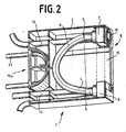
- FIG. 2 one recognizes a hose cassette 1 according to the invention, which in the cassette shaft 20 of the FIG. 1 is insertable.
- One first recognizes a cassette housing 3, in which a flexible pump hose segment 4 is arranged.
- the two ends 5, 6 of the pump tube segment 4 are in fixed to the cassette housing 3 by means of a first fixing element 7 and a second fixing element 8.
- the first fixing element 7 and the second fixing element 8 are arranged in the region of the first end face 9 of the cassette housing 3.
- the cassette housing 3 has a recess 10 for engagement of the roller wheel 11 of the pump 2 in the interior of the cassette housing 3.
- the recess 10 is arranged substantially in the region of the first end face 9 between the first fixing element 7 and the second fixing element 8.
- the pump tube segment 4 is arranged in the tube cassette 1 with not inserted into the pump 2 tube cassette 1 along an angle of about 180 ° spanning circle segment K extending. It is understood that the term of the circle segment K is not necessarily to be understood as running exactly along a circular arc, but represents the course, which at a given angle of the two ends 5, 6 to each other (here 180 °) results.
- the fixing elements 7, 8 have two hose lines 13, 14 which each hydrostatically communicate with one end 5, 6 of the pump hose segment 4 or are connected thereto, wherein in this embodiment the hose lines 13, 14 are substantially antiparallel to the ends 5 , 6 of the pump tube segment 4 are arranged to extend.
- the hose lines 13, 14 pass out of the cassette housing 3 through the second end face 15a of the cassette housing 3 which is opposite the first end face 9.
- a fixing element 7 is arranged in the region of the first end face 9 and with the pump tube segment 4 hydrostatically communicating or hereby connected flexible membrane 15 set. This interacts with inserted in the operating position cassette with the force / displacement transducer 19 and then represents a pressure measuring device.
- a drain hose 23 In the FIG. 2 Finally, one recognizes a drain hose 23.
- the cassette shaft 20 as a guide element for a translational movement of the Schlauchkasstte 1 in directions orthogonal to the first end face 9 represents.
- a not shown detent recess 17 is arranged, which interacts with the latching hook 18 of the pump 2 in the operating position of the hose cassette 1 detent.
- a button 24, which represents a release element for releasing the latching connection Upon actuation of the knob 24 of the latching hook 18 is pulled in the axial direction of the roller wheel 11 and thus gives the latching recess 17 of the cassette housing 3 free. Due to the tension of the pump hose segment (4) in the operating position, the hose cassette 1 is then automatically ejected from the pump housing 16.
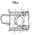
- the tube cassette 1 is first placed in the axial direction of the roller wheel 11, wherein the roller wheel 11 passes through the recess 10 of the side surface 12. Thereafter, the tube cassette 1 is brought from the mounting position to the operating position, either by displacement of the tube cassette 1 in the direction radially to the roller wheel 11 or by pivoting the tube cassette 1 about a pivot axis which is outside the roller wheel 11.
- This variant of the invention will usually be used when replacing one in a cassette slot 20 arranged roller wheel 11 is a free standing outside the pump housing 16 and rotating roller wheel 11 is to be established.
Landscapes
- Engineering & Computer Science (AREA)
- Mechanical Engineering (AREA)
- General Engineering & Computer Science (AREA)
- Reciprocating Pumps (AREA)
Description
- Die Erfindung betrifft eine Schlauchkassette gemäß Oberbegriff des Anspruchs 1. Die Erfindung betrifft des Weiteren ein peristaltisches Schlauchpumpensystem mit einer solchen Schlauchkassette.
- Peristaltische Schlauchpumpen werden beispielsweise als Saug-und Spülpumpen für medizinische Zwecke, insbesondere in der minimalinvasiven Chirurgie, eingesetzt. Konkrete Anwendungsbereiche sind die Arthroskopie, Laparoskopie, Urologie, Hysteroskopie und Cystoskopie. Bei medizinischen Anwendungen ist insbesondere eine allen Anforderungen genügende Sterilität geboten, und aus diesem Grunde wird die Schlauchkassette üblicherweise nach einer Anwendung verworfen, um eine Kreuzkontämination zwischen verschiedenen Patienten zu vermeiden. Die Schlauchkassetten müssen folglich einerseits preiswert in der Herstellung sein und andererseits insbesondere eine einfache Handhabung durch Bedienpersonen ermöglichen, und zwar bei der Verbindung der Schlauchkassette mit der Pumpe sowie dem Lösen hiervon.
- Im Rahmen von bekannten peristaltischen Pumpen gibt es grundsätzlich zwei verschiedene Grundkonzeptionen. Die erste Grundkonzeption besteht darin, dass der um das Rollenrad angeordnete Schlauch mittels eines Andruckbügels oder dergleichen gegen das Rollenrad gedrückt wird. Solche peristaltischen Schlauchpumpensysteme sind beispielsweise aus den Literaturstellen
US 4,798,580 ,US 5,044,902 ,US 5,213,483 undDE 100 62 600.9 A1 bekannt. Mit einer Verschluss-Hebelmechanik wird der Schlauch fixiert und mittels des Andruckbügels gegen das Rollenrad gedrückt. - Die zweite Grundkonzeption, von welcher die Erfindung im Kern ausgeht, besteht darin, dass der Schlauch durch eine Zugkraft geeigneter Größe mit genügendem Umfassungswinkel um das Rollenrad gezogen wird. Hierdurch wird ein Anpressbügel oder dergleichen entbehrlich. Die Zugkraft ist dabei in Abstimmung mit den elastischen Eigenschaften des Schlauches so zu dimensionieren, dass im Bereich einer Rolle eines Rollenrades der Innenquerschnitt des Schlauches auf praktisch Null reduziert ist. Hierzu ist beispielsweise aus der Literaturstelle
DE 199 60 668 Cl bekannt, dass im Rahmen einer Schlauchkassette zumindest ein an das Kreissegment anschließender Schenkel des Pumpschlauchsegments in dem Kassettengehäuse in Längsrichtung des Schlauches zwischen einer Montageposition und einer Betriebsposition verschieblich gelagert ist. Dies hat sich grundsätzlich hervorragend bewährt, baut jedoch relativ aufwändig und ist in der Herstellung folglich teuer. - Eine Schlauchkassette ist aus der Literaturstelle
US 4,537,561 bekannt. Hierbei ist im Rahmen einer Schlauchkassette ein geradlinig verlaufendes Pumpschlauchsegment eingerichtet. Die Schlauchkassette wird orthogonal zur Erstreckung des Pumpschlauchsegments in die peristaltische Pumpe eingeschoben, wobei das Pumpschlauchsegment mit dem Rollenrad in Kontakt kommt und im Zuge des Einschiebens der Schlauchkassette mit einem geringen Umfassungswinkel um das Rollenrad gespannt wird. Bei der insofern bekannten Schlauchkassette ist es nachteilig, dass auf Grund der Geometrie der Zusammenhänge ein ausreichender Druck auf das Pumpschlauchsegment durch das Rollenrad nur mit verhältnismäßig hohen Kräften erreicht wird. Einerseits erfordert dies hohe Kräfte beim Einschieben der Schlauchkassette, andererseits werden Bauelemente der Schlauchkassette mit Biegemomenten beaufschlagt, wodurch diese relativ stabil bauen muss. - Schlauchkassetten des eingangs genannten Aufbaus sind aus den Literaturstellen
US-5,927,956 A ,WO 95/04886 A WO 2005/111424 A bekannt. - Der Erfindung liegt daher das technische Problem zugrunde, eine Schlauchkassette sowie ein peristaltisches Schlauchpumpensystem anzugeben, wobei die Schlauchkassette einfach und sicher montierbar ist, einfach baut und eine hohe Betriebssicherheit aufweist.
- Zur Lösung dieses technischen Problems lehrt die Erfindung, den Gegenstand des Anspruchs 1. Dabei ist Pumpschlauchsegment bogenaussenseitig nicht abgestützt, sondern frei von anderen Bauteilen. Vorzugsweise überspannt das Kreissegment einen Winkel von zumindest 120° bis zumindest 160°, idealerweise ca. 180°. Mit anderen Worten ausgedrückt, die Enden des Pumpschlauchsegements stehen zueinander in einem Winkel von 90° bis 220°, vorzugsweise von 150° bis 200°, idealerweise von 170° bis 190°, beispielsweise ca. 180°. Hierbei ist ein Winkel von 0° als der Winkel der Enden zueinander zu verstehen, den die Enden bei geradliniger Erstreckung des Pumpschlauchsegments zueinander haben.
- Hiermit wird erreicht, dass die Enden des Pumpschlauchsegmentes praktisch ausschließlich auf Zug belastet sind. Zudem ist durch den hohen Umfassungswinkel eine sichere Abdichtung des Schlauches durch das Rollenrad und folglich ein hoher erreichbarer peristaltischer Druck gewährleistet, und zwar ohne Andruckbügel oder Stützflächen oder dergleichen. In jedem Falle ist es entbehrlich, Andruckmittel zum Andrücken des Pumpschlauchsegments an das Rollenrad bei in der Pumpe eingesetzter Schlauchkassette einzurichten. Ebenso sind verschiebliche Enden des Pumpschlauchsegments zum Zwecke der Spannung des Pumpschlauchsegments um das Rollenrad enbehrlich. Die Enden des Pumpschlauchsegments sind vielmehr gegenüber dem Kasettengehäuse ortsfest.
- Im Rahmen der Erfindung sind zwei grundsätzlich verschiedene Varianten möglich.
- Zum einen kann es vorgesehen sein, dass sich die Ausnehmung für das Rollenrad im Bereich der ersten Stirnfläche zwischen dem ersten Fixierelement und dem zweiten Fixierelement erstreckt. Dann erfolgt der Einsatz der Schlauchkassette durch eine im Wesentlichen lineare Bewegung aus einer Montageposition in eine Betriebsposition in Richtung radial zum Rollenrad.
- Zum anderen kann sich die Ausnehmung in einem Bereich einer zur ersten Stirnfläche orthogonalen und zum Kreissegment parallelen Seitenfläche des Kassettengehäuses erstrecken. Dann kann das Einsetzen der Kassette in eine Montagestellung durch Aufstecken der Kassette auf das Rollenrad in axialer Richtung erfolgen. Hieran schließt sich entweder eine lineare Verschiebung der Kassette in radialer Richtung des Rollenrades an oder eine Schwenkbewegung der Kassette mit Bewegungskomponente radial zum Rollenrad. Beides Bewegungen enden in der Betriebsposition. In jeder der vorstehenden Varianten wird das Pumpschlauchsegment bei Bewegung der Schlauchkassette in die Betriebsposition um das Rollenrad gespannt.
- Erfindungsgemäß ist vorgesehen, dass die Fixierelemente zwei jeweils mit einem Ende des Pumpschlauchsegments hydrostatisch kommunizierende Schlauchleitungen aufweisen, wobei die Schlauchleitungen im Wesentlichen antiparallel zu den Enden des Pumpschlauchsegments verlaufend angeordnet sind. Dann können die Schlauchleitungen insbesondere durch eine der ersten Stirnfläche gegenüberliegenden zweiten Stirnfläche des Kassettengehäuses austreten. Der Begriff antiparallel bezieht sich hierbei auf die Strömungsrichtung eines Fluids in den Enden des Pumpschlauchsegments bzw. den Schlauchleitungen. Diese Ausführungsform eignet sich insbesondere für eine Variante der Erfindung, in welcher die Schlauchkassette durch eine lineare Bewegung in Richtung radial zum Rollenrad in die Betriebsposition verschoben wird. In dieser Ausführungsform ist es zudem insbesondere unschwer einrichtbar, dass das Rollenrad in einem Pumpengehäuse innenliegend angeordnet ist, wodurch jegliche Verletzungsgefahr bzw. Eingriffsmöglichkeit im Bereich des Rollenrades ausgeschlossen werden kann. Die Führung der Linearbewegung der Schlauchkassette erfolgt dann durch einen zur Form der Schlauchkassette komplementären Kassettenschacht.
- In einem erfindungsgemäßen Kassettengehäuse können auch zwei (oder mehr) im Wesentlichen parallel zueinander gestapelt verlaufende Pumpschlauchsegmente angeordnet sein. In entsprechender Weise sind dann auch die an die Enden der Pumpschlauchsegmente angeschlossenen Schlauchleitungen zweifach auszuführen. In dieser Ausführungsform sind typischerweise zwei Rollenräder im Rahmen der Pumpe eingerichtet sind, wobei jeweils ein Pumpschlauchsegment einem Rollenrad zugeordnet ist. In dieser Ausführungsform kann auch vorgesehen sein, dass beide Rollenräder getrennt ansteuerbar sind. Auf diese Weise kann beispielsweise eine unabhängige Steuerung einer Saugfunktion mittels eines Pumpschlauchsegments und einer Spülfunktion mittels des anderen Pumpschlauchsegments erfolgen. Es ist aber auch möglich mit nur einem Rollenrad zu arbeiten, wobei das Rollenrad dann die erforderliche Breite aufweist, um beide Pumpschlauchsegmente gleichzeitig um das Rollenrad zu spannen.
- Des Weiteren kann es vorgesehen sein, dass zumindest ein Fixierelement eine im Bereich der ersten Stirnfläche angeordnete und mit dem Pumpschlauchsegment hydrostatisch kommunizierende flexible Membran aufweist. In der Betriebsstellung der Schlauchkassette ist diese flexible Membran dann in Verbindung mit einem Kraft- und/oder Wegaufnehmer, wodurch in der Betriebsposition der Schlauchkassette letztlich eine Druckmessung möglich ist. Es wird sich in der Regel empfehlen, diese flexible Membran an jedem Fixierelement anzuordnen, welches die Druckseite des Pumpschlauchsegments darstellt.
- Die Erfindung betrifft des Weiteren ein peristaltisches Schlauchpumpensystem mit zumindest einer erfindungsgemäßen Schlauchkassette, mit einer Pumpe, welche zumindest ein Pumpengehäuse sowie ein angetriebenes Rollenrad aufweist, wobei die Schlauchkassette und das Pumpengehäuse zueinander komplementäre Verbindungselemente aufweisen, welche mit der Maßgabe zueinander angeordnet sind, dass das Pumpschlauchsegment bei mit dem Pumpengehäuse verbundener und in eine Betriebsposition bewegter Schlauchkassette um das Rollenrad herum gespannt ist.
- Als Verbindungselemente kommen insbesondere lösbare Rastverbindungen in Frage. Im Einzelnen können die Verbindungselemente die folgenden Komponenten aufweisen: a) zumindest ein an oder in dem Pumpenhäuse angeordnetes Führungselement für eine Translationsbewegung der Schlauchkassette in Richtungen orthogonal zur ersten Stirnfläche (und radial zum Rollenrad), b) zumindest eine Rastverbindung mit einem an dem Kassettengehäuse angebrachten ersten Rastelement und einem an dem Pumpengehäuse angebrachten und zum ersten Rastelement komplementären zweiten Rastelement, wobei die Rastverbindung bei Verschieben der Schlauchkassette in Richtung der Betriebsposition in diese einrastet, und c) mit einem Löseelement zur Lösung der Rastverbindung. Alternativ hierzu können die Verbindungselemente die folgenden Komponenten aufweisen: a) zumindest eine an oder in dem Pumpengehäuse angeordnete und im Wesentlichen parallel zur Drehachse des Rollenrades verlaufende Schwenkachse, um welche die Schlauchkassette verschwenkbar ist, wobei die Schwenkachse gegenüber dem Mittelpunkt des Pumpschlauchsegments, bezogen auf die erste Stirnfläche, seitlich verschoben ist, b) eine Rastverbindung mit einem an dem Kassettengehäuse angebrachten ersten Rastelement und einem an dem Pumpengehäuse angebrachten und zum ersten Rastelement komplementären zweiten Rastelement, wobei die Rastverbindung bei Verschwenken der Schlauchkassette um die Schwenkachse in die Betriebsposition in dieser einrastet und c) mit einem Löseelement zum Lösen der Rastverbindung. In beiden Fällen wird die Schlauchkassette in einfacher Weise und mit ledilglich einer Hand in Richtung der Betriebsposition verschoben bzw. verschwenkt, bis die Rastverbindung einrastet. Durch Betätigung des Löseelements wird dann nicht nur die Rastverbindung gelöst, sondern durch die in der Betriebsposition eingerichtete Spannung des Pumpschlauchsegments erfolgt auch ein selbsttätiger Auswurf der Schlauchkassette, insbesondere im Falle der Variante mit Translationsbewegungen zwischen der Montage- und Betriebsposition.
- Für eine Schlauchkassette mit flexibler Membran kann vorgesehen sein, dass das Pumpengehäuse einen in Betriebsposition der Schlauchkassette mit der flexiblen Membran der Schlauchkassette verbundenen Kraft- und/oder Wegaufnehmer aufweist. Hierdurch wird die durch die flexible Membran vermittelte Druckkraft des Fluids in dem Fixierelement in ein elektrisches Signal umgewandelt, welches dann zur Druckanzeige und/oder Steuerung bzw. Regelung verwendet werden kann.
- Eine erfindungsgemäße peristaltische Pumpe weist typischerweise ein elektromotorisches Antriebsmittel für das Rollenrad auf. Hierbei kann es sich um einen Gleichstrommotor, Wechselstrommotor oder Schrittschaltmotor handeln. Zwischen einer Abtriebswelle des Motors und der Antriebswelle des Rollenrades kann ein mechanisches Reduktionsgetriebe vorgesehen sein. Es ist aber auch ein direkter Antrieb möglich, beispielsweise im Falle des Schrittschaltmotors. Typischerweise ist die Drehzahl des Motors steuer- bzw. regelbar. Hierzu wird typischerweise eine Steuerelektronik eingerichtet sein, wobei eine Bedienperson durch Steuerelemente, wie Tasten oder Schalter, die gewünschten Flussraten bzw. Drucke einstellen kann, und die Steuerelektronik dann gemäß einem Betriebsprogramm die korrelierten Drehzahlen ansteuert und regelt. Die Steuerelektronik wird zudem ggf. im Pumpschlauchsegment gemessenene Druckwerte mit Solldruckwerten oder maximalen Druckwerten vergleichen und die Drehzahl des Rollenrades in entsprechender Weise ansteuern. Im Extremfall kann hierbei das Rollenrad auch in reverse Drehrichtung angesteuert werden. Eine erfindungsgemäße peristaltische Pumpe kann alternativ bzw. wahlweise mit Netzstrom oder mit Batterie bzw. Akkumulator betrieben werden. Die Technologien für Antrieb sowie Steuerung bzw. Regelung eines Rollenrades einer peristaltischen Schlauchpumpe sind bekannt und brauchen daher hier nicht näher erläutert zu werden.
- Die Schlauchkassette bzw. das Kassettengehäuse kann eine Codierung aufweisen, welche spezifisch für eine Zweckbestimmung, wie beispielsweise Arthroskopie, Laparoskopie, Urologie oder Hysteroskopie ist. In der Betriebsposition der Schlauchkassette kann dann durch geeignete Mittel der Pumpe dieser Code ausgelesen werden. Diese Mittel stehen dann mit der elektronischen Steuerung in Verbindung und steuern für die jeweilige Anwendung geeignete Arbeitsparameter gemäß dem Betriebsprogramm an. Hierbei kann die Codierung mechanisch, mittels eines Transponders oder smart labels oder dergleichen erfolgen.
- Im Folgenden wird die Erfindung anhand von lediglich Ausführungsbeispiele darstellenden Figuren näher erläutert. Es zeigen:
- Figur 1:
- eine Außenansicht einer erfindungsgemäßen peristaltischen Pumpe,
- Figur 2:
- Einblick in eine erfindungsgemäße Schlauchkassette mit entfernter Seitenwandung,
- Figur 3:
- die wesentlichen mechanischen Komponenten des Gegenstandes der
Figur 1 und - Figur 4:
- eine Variante eines erfindungsgemäßen peristaltischen Schlauchpumpensystems.
- In der
Figur 1 erkennt man in Außenansicht eine Pumpe 2, welche ein Pumpengehäuse 16 sowie zumindest ein angetriebenes Rollenrad 11 aufweist. Das Rollenrad 11 ist in einem Kassettenschacht 20 im Inneren des Pumpengehäuses 16 angeordnet. Im Kassettenschacht 20 erkennt man des Weiteren einen lösbaren Rasthaken 18 sowie einen Kraft- bzw. Wegaufnehmer 19. - In der
Figur 3 erkennt man die wesentlichen mechanischen Komponenten der Pumpe 2. Das Rollenrad 11 wird durch eine Motor-/Getriebeeinheit 21 angetrieben. Im Rahmen der Motor-/Getriebeeinheit 21 ist ein elektrisch ansteuerbarer Schrittschaltmotor eingerichtet, welcher mit der Antriebswelle des Rollenrades 11 verbunden ist. Am der Öffnung gegenüberliegenden Ende des Kassettenschachtes 20 ist der Kraft- bzw. Wegaufnehmer 19 angeordnet. Des Weiteren erkennt man ein in axialer Richtung betätigbares Ventilelement, welches in Zusammenwirkung mit einer Schlauchleitung bei eingelegter Kassette ein sog. Pinch-Ventil bildet. Hierbei drückt das Betätigungselement 22 bei Aktivierung die Schlauchleitung platt, so dass diese undurchlässig für das Fluid wird. - In der
Figur 2 erkennt man eine erfindungsgemäße Schlauchkassette 1, welche in den Kassettenschacht 20 derFigur 1 einschiebbar ist. Man erkennt zunächst ein Kassettengehäuse 3, in welchem ein flexibles Pumpschlauchsegment 4 angeordnet ist. Die beiden Enden 5, 6 des Pumpschlauchsegments 4 sind in dem Kassettengehäuse 3 mittels eines ersten Fixierelements 7 und eines zweiten Fixierelements 8 fixiert. Das erste Fixierelement 7 und das zweite Fixierelement 8 sind im Bereich der ersten Stirnfläche 9 des Kassettengehäuses 3 angeordnet. Das Kassettengehäuse 3 weist eine Ausnehmung 10 zum Eingriff des Rollenrades 11 der Pumpe 2 in das Innere des Kassettengehäuses 3 auf. Die Ausnehmung 10 ist dabei im Wesentlichen im Bereich der ersten Stirnfläche 9 zwischen dem ersten Fixierelement 7 und dem zweiten Fixierelement 8 angeordnet. Sie erstreckt sich jedoch auch teilweise in die zur ersten Stirnfläche 9 orthogonalen Seitenfläche 12 des Kassettengehäuses 3, so dass das Kassettengehäuse 3 vollständig über das Rollenrad 11 schiebbar ist. Das Pumpschlauchsegment 4 ist in der Schlauchkassette 1 bei nicht in die Pumpe 2 eingesetzter Schlauchkassette 1 entlang eines einen Winkel von ca. 180° überspannenden Kreissegmentes K verlaufend angeordnet. Hierbei versteht es sich, dass der Begriff des Kreissegmentes K nicht notwendigerweise als exakt entlang einem Kreisbogen verlaufend zu verstehen ist, sondern den Verlauf darstellt, welcher sich bei vorgegebenem Winkel der beiden Enden 5, 6. zueinander (hier 180°) ergibt. - Der
Figur 2 entnimmt man des Weiteren, dass die Fixierelemente 7, 8 zwei jeweils mit einem Ende 5, 6 des Pumpschlauchsegments 4 hydrostatisch kommunizierende bzw. hiermit verbundene Schlauchleitungen 13, 14 aufweisen, wobei in diesem Ausführungsbeispiel die Schlauchleitungen 13, 14 im Wesentlichen antiparallel zu den Enden 5, 6 des Pumpschlauchsegments 4 verlaufend angeordnet sind. Die Schlauchleitungen 13, 14 treten durch die der ersten Stirnfläche 9 gegenüberliegende zweite Stirnfläche 15a des Kassettengehäuses 3 aus dem Kassettengehäuse 3 aus. Bei einem Fixierelement 7 ist eine im Bereich der ersten Stirnfläche 9 angeordnete und mit dem Pumpschlauchsegment 4 hydrostatisch kommunizierende bzw. hiermit verbundene flexible Membran 15 eingerichtet. Diese wechselwirkt bei in Betriebsposition eingeschobener Kassette mit dem Kraft-/Wegaufnehmer 19 und stellt dann eine Druckmessvorrichtung dar. In derFigur 2 erkennt man schließlich einen Ablaufschlauch 23. - Aus einer vergleichenden Betrachtung der
Figuren 1 bis 3 erkennt man, dass der Kassettenschacht 20 als Führungselement für eine Translationsbewegung der Schlauchkasstte 1 in Richtungen orthogonal zur ersten Stirnfläche 9 darstellt. An dem Kassettengehäuse 3 ist eine nicht näher dargestellte Rastausnehmung 17 eingerichtet, welche mit dem Rasthaken 18 der Pumpe 2 in Betriebsstellung der Schlauchkassette 1 rastend wechselwirkt. Schließlich erkennt man einen Knopf 24, welcher ein Löseelement zum Lösen der Rastverbindung darstellt. Bei Betätigung des Knopfes 24 wird der Rasthaken 18 in axiale Richtung des Rollenrades 11 gezogen und gibt somit die Rastausnehmung 17 des Kassettengehäuses 3 frei. Aufgrund der Spannung des Pumpschlauchsegments (4) in der Betriebsstellung wird dann die Schlauchkassette 1 aus dem Pumpengehäuse 16 automatisch ausgeworfen. - In der
Figur 4 erkennt man eine Variante des erfindungsgemä-βen Systems. Hier wird die Schlauchkassette 1 zunächst in axialer Richtung des Rollenrades 11 aufgesetzt, wobei das Rollenrad 11 durch die Ausnehmung 10 der Seitenfläche 12 hindurchtritt. Hiernach wird die Schlauchkassette 1 aus der Montageposition in die Betriebsposition gebracht, entweder durch Verschiebung der Schlauchkassette 1 in Richtung radial zum Rollenrad 11 oder durch Verschwenken der Schlauchkassette 1 um eine Schwenkachse, die außerhalb des Rollenrades 11 liegt. Grundsätzlich gelten alle vorstehend erläuterten Details analog. Diese Variante der Erfindung wird in der Regel dann einzusetzen sein, wenn an Stelle eines in einem Kassettenschacht 20 angeordneten Rollenrades 11 ein außerhalb des Pumpgehäuses 16 freistehendes und rotierendes Rollenrad 11 einzurichten ist.
Claims (10)
- Schlauchkassette (1) für eine peristaltische Pumpe (2)
mit einem Kassettengehäuse (3),
mit einem durch das Kassettengehäuse (3) verlaufenden flexiblen Pumpschlauchsegment (4),
wobei beide Enden (5), (6) des Pumpschlauchsegments (4) in dem Kassettengehäuse (3) mittels eines ersten Fixierelements (7) und eines zweiten Fixierelements (8) ortsfest fixiert sind,
wobei das erste Fixierelement (7) und das zweite Fixierelement (8) im Bereich einer ersten Stirnfläche (9) des Kassettengehäuses (3) angeordnet sind, und
wobei das Kassettengehäuse (3) eine Ausnehmung (10) zum Eingriff eines Rollenrades (11) der Pumpe (2) in das Innere der Kassettengehäuses (3) aufweist, und
wobei das Pumpschlauchsegment (4) in der Schlauchkassette (1) bei nicht in die Pumpe (2) eingesetzter Schlauchkassette (1) entlang eines zumindest einen Winkel von 90° überspannenden Kreissegments (K) verläuft.
dadurch gekennzeichnet,
dass die Fixierelemente (7), (8) zwei jeweils mit einem Ende (5), (6) des Pumpschlauchsegments (4) hydrostatisch kommunizierende Schlauchleitungen (13), (14) aufweisen, wobei die Schlauchleitungen (13), (14) antiparallel, in Bezug auf die Strömungsrichtung eines gepumpten Fluids, zu den Enden des Pumpschlauchsegments (4) verlaufend angeordnet sind. - Schlauchkassette (1) nach Anspruch 1, dadurch gekennzeichnet, dass sich die Ausnehmung (10) in einem Bereich der ersten Stirnfläche (9) zwischen dem ersten Fixierelement (7) und dem zweiten Fixierelement (8) erstreckt und/oder dass sich die Ausnehmung (10) in einem Bereich einer zur ersten Stirnfläche (9) orthogonalen und zum Kreissegment (K) parallelen Seitenfläche (12) des Kassettengehäuses (3) erstreckt.
- Schlauchkassette (1) nach einem der Ansprüche 1 oder 2, dadurch gekennzeichnet, dass das Kreissegment (K) einen Winkel von zumindest 120°, vorzugsweise zumindest 140°, höchstvorzugsweise zumindest 160°, überspannt.
- Schlauchkassette (1) nach einem der Ansprüche 1 bis 3, dadurch gekennzeichnet, dass die Schlauchleitungen (13), (14) durch eine der ersten Stirnfläche (9) gegenüberliegende zweite Stirnfläche (15a) des Kassettengehäuses (3) austreten.
- Schlauchkassette (1) nach einem der Ansprüche 1 bis 4, dadurch gekennzeichnet, dass in dem Kassettengehäuse (3) zwei oder mehr im Wesentlichen parallel zueinander gestapelt verlaufende Pumpschlauchsegmente (4) angeordnet sind.
- Schlauchkassette (1) nach einem der Ansprüche 1 bis 5, dadurch gekennzeichnet, dass zumindest ein Fixierelement (7), (8) eine im Bereich der ersten Stirnfläche (9) angeordnete und mit dem Pumpschlauchsegment (4) hydrostatisch kommunizierende flexible Membran (15) aufweist.
- Peristaltisches Schlauchpumpensystem
mit einer Schlauchkassette (1) nach einem der Ansprüche 1 bis 6,
mit einer Pumpe (2), welche ein Pumpengehäuse (16) sowie zumindest ein angetriebenes Rollenrad (11) aufweist,
wobei die Schlauchkassette (1) und das Pumpengehäuse (16) zueinander komplementäre Verbindungselemente (17), (18) aufweisen, welche mit der Maßgabe zueinander angeordnet sind, dass das Pumpschlauchsegment (4) bei mit dem Pumpenhäuse (16) verbundener und in eine Betriebsposition bewegter Schlauchkassette (1) um das Rollenrad (11) herumgespannt ist. - Peristaltisches Schlauchpumpensystem nach Anspruch 7, wobei die Verbindungselemente (17), (18) die folgenden Komponenten aufweisen:a) zumindest ein an oder in dem Pumpengehäuse (16) angeordnetes Führungselement (19) für eine Translationsbewegung der Schlauchkassette (1) in Richtungen orthogonal zur ersten Stirnfläche (9),b) zumindest eine Rastverbindung mit einem an dem Kassettengehäuse (3) angebrachten ersten Rastelement (17) und einem an dem Pumpengehäuse (16) angebrachten und zum ersten Rastelement (17) komplementären zweiten Rastelement (18), wobei die Rastverbindung bei Verschiebung der Schlauchkassette (1) in Richtung der Translationsbewegung aus einer Montageposition in eine Betriebsposition einrastet undc) mit einem Löseelement zur Lösung der Rastverbindung
- Peristaltisches Schlauchpumpensystem nach Anspruch 7, wobei die Verbindungselemente (17), (18) die folgenden Komponenten aufweisen:a) zumindest eine an oder in dem Pumpengehäuse (16) angeordnete und im Wesentlichen parallel zur Drehachse des Rollenrades (11) verlaufende Schwenkachse, um welche die Schlauchkassette (1) verschwenkbar ist, wobei die Schwenkachse gegenüber dem Mittelpunkt (Z) des Pumpschlauchsegments (4), bezogen auf die erste Stirnfläche (9), seitlich verschoben ist,b) eine Rastverbindung mit einem an dem Kassettengehäuse (3) angebrachten ersten Rastelement (17) und einem an dem Pumpengehäuse (16) angebrachten und zum ersten Rastelement (17) komplementären zweiten Rastelement (18), wobei die Rastverbindung bei Verschwenken der Schlauchkassette (1) aus einer Montageposition in eine Betriebsposition um die Schwenkachse in die Betriebsposition in dieser einrastet undc) mit einem Löseelement zur Lösung der Rastverbindung.
- Peristaltisches Schlauchpumpensystem nach Anspruch 7 oder 8 oder 9, wobei das Pumpengehäuse (16) einen in Betriebsposition der Schlauchkassette (1) mit der flexiblen Membran (15) der Schlauchkassette (1) verbundenen Kraft- und/oder Wegaufnehmer (19) aufweist.
Applications Claiming Priority (1)
| Application Number | Priority Date | Filing Date | Title |
|---|---|---|---|
| DE102006008325A DE102006008325B4 (de) | 2006-02-20 | 2006-02-20 | Schlauchkassette für eine peristaltische Pumpe |
Publications (2)
| Publication Number | Publication Date |
|---|---|
| EP1820967A1 EP1820967A1 (de) | 2007-08-22 |
| EP1820967B1 true EP1820967B1 (de) | 2009-06-03 |
Family
ID=37890536
Family Applications (1)
| Application Number | Title | Priority Date | Filing Date |
|---|---|---|---|
| EP07001140A Not-in-force EP1820967B1 (de) | 2006-02-20 | 2007-01-19 | Schlauchkassette für eine peristaltische Pumpe |
Country Status (6)
| Country | Link |
|---|---|
| US (1) | US8491285B2 (de) |
| EP (1) | EP1820967B1 (de) |
| JP (1) | JP5224696B2 (de) |
| AT (1) | ATE433051T1 (de) |
| DE (2) | DE102006008325B4 (de) |
| ES (1) | ES2329087T3 (de) |
Families Citing this family (51)
| Publication number | Priority date | Publication date | Assignee | Title |
|---|---|---|---|---|
| JP2009530041A (ja) | 2006-03-23 | 2009-08-27 | ザ・ペン・ステート・リサーチ・ファンデーション | 拡張可能なインペラポンプを有する心臓補助装置 |
| EP2140890A1 (de) * | 2008-07-03 | 2010-01-06 | Bien-Air Holding SA | Schlauchpumpe und Bewässerungslinie |
| GB2467605B (en) * | 2009-02-10 | 2014-09-24 | Watson Marlow Ltd | A peristaltic pump |
| US8109899B2 (en) * | 2009-07-06 | 2012-02-07 | Likvor Ab | Fully automated method of measuring and regulating cerebrospinal fluid parameters using disposable tube-set |
| DE102009029305A1 (de) * | 2009-09-09 | 2011-03-10 | Endress + Hauser Conducta Gesellschaft für Mess- und Regeltechnik mbH + Co. KG | Analysegerät zur automatisierten Bestimmung einer Messgröße einer Flüssigkeitsprobe |
| USD721801S1 (en) * | 2010-05-03 | 2015-01-27 | Medical Vision Ab | Cassette for a peristaltic pump |
| USD773037S1 (en) | 2010-05-03 | 2016-11-29 | Medical Vision Ab | Cassette for a peristaltic pump |
| USD745963S1 (en) * | 2010-05-03 | 2015-12-22 | Medical Vision Ab | Cassette for a peristaltic pump |
| US9138518B2 (en) | 2011-01-06 | 2015-09-22 | Thoratec Corporation | Percutaneous heart pump |
| US9289110B2 (en) | 2012-04-05 | 2016-03-22 | Stryker Corporation | Control for surgical fluid management pump system |
| US9603990B2 (en) | 2012-04-05 | 2017-03-28 | Stryker Corporation | Cassette for a surgical fluid management pump system |
| US9492071B2 (en) | 2012-04-05 | 2016-11-15 | Stryker Corporation | In-joint sensor for a surgical fluid management pump system |
| DE102013008159A1 (de) | 2012-05-14 | 2013-11-14 | Thoratec Corporation | Mantelsystem für Katheterpumpe |
| US9446179B2 (en) | 2012-05-14 | 2016-09-20 | Thoratec Corporation | Distal bearing support |
| US8721517B2 (en) | 2012-05-14 | 2014-05-13 | Thoratec Corporation | Impeller for catheter pump |
| DE102013008168A1 (de) | 2012-05-14 | 2013-11-14 | Thoratec Corporation | Laufrad für Katheterpumpe |
| USD732663S1 (en) * | 2012-05-24 | 2015-06-23 | Fresenius Medical Care Holdings, Inc. | Fluid tubing guide |
| DE102012012525A1 (de) * | 2012-06-26 | 2014-01-02 | Karl Storz Gmbh & Co. Kg | Pumpsystem, Schlauchpumpe und Schlauchkassette sowie Verfahren zum Konfigurieren eines Pumpsystems |
| US9358329B2 (en) | 2012-07-03 | 2016-06-07 | Thoratec Corporation | Catheter pump |
| USD693463S1 (en) * | 2012-08-13 | 2013-11-12 | Karl Storz Gmbh & Co. Kg | Tubing cassette |
| USD709611S1 (en) * | 2012-08-13 | 2014-07-22 | Karl Storz Gmbh & Co. Kg | Support guide for tubing cassette system |
| BR302013000587S1 (pt) * | 2012-08-13 | 2014-06-17 | Storz Karl Gmbh & Co Kg | Configuração aplicada em dispositivo médico. |
| JP6530367B2 (ja) | 2013-03-13 | 2019-06-12 | ティーシーワン エルエルシー | 流体導出入システム |
| US11033728B2 (en) | 2013-03-13 | 2021-06-15 | Tc1 Llc | Fluid handling system |
| USD696769S1 (en) | 2013-03-14 | 2013-12-31 | Thoratec Corporation | Catheter pump console interface |
| USD746975S1 (en) | 2013-03-14 | 2016-01-05 | Thoratec Corporation | Catheter pump console |
| EP3797810B1 (de) | 2013-03-15 | 2025-09-03 | Tc1 Llc | Katheterpumpenanordnung mit einem stator |
| US9308302B2 (en) | 2013-03-15 | 2016-04-12 | Thoratec Corporation | Catheter pump assembly including a stator |
| GB2518806B (en) * | 2013-06-26 | 2018-04-11 | Intelligent Energy Ltd | Pump assembly |
| USD735320S1 (en) * | 2013-11-30 | 2015-07-28 | Zevex, Inc. | Enteral feeding pump cassette |
| USD739931S1 (en) * | 2013-11-30 | 2015-09-29 | Zevex, Inc. | Enteral feeding pump cassette |
| JP5863871B2 (ja) * | 2014-04-15 | 2016-02-17 | 日機装株式会社 | 装着部材及びしごき型ポンプ |
| EP3131615B1 (de) | 2014-04-15 | 2021-06-09 | Tc1 Llc | Sensoren für katheterpumpen |
| WO2015160980A1 (en) | 2014-04-15 | 2015-10-22 | Thoratec Corporation | Heart pump providing adjustable out flow |
| US10583232B2 (en) | 2014-04-15 | 2020-03-10 | Tc1 Llc | Catheter pump with off-set motor position |
| JP6300200B2 (ja) * | 2014-04-18 | 2018-03-28 | パナソニックIpマネジメント株式会社 | チューブポンプ及び流体送出方法 |
| WO2016028644A1 (en) | 2014-08-18 | 2016-02-25 | Thoratec Corporation | Guide features for percutaneous catheter pump |
| CN105979982B (zh) * | 2014-12-12 | 2017-11-14 | 泽维克斯公司 | 输液泵盒以及被构造成有助于盒移除的盒接口 |
| WO2016118777A1 (en) | 2015-01-22 | 2016-07-28 | Thoratec Corporation | Reduced rotational mass motor assembly for catheter pump |
| JP6813484B2 (ja) | 2015-06-24 | 2021-01-13 | 日機装株式会社 | 血液浄化装置 |
| US20170106199A1 (en) | 2015-10-16 | 2017-04-20 | Brady L. WOOLFORD | Integrated pump control for dynamic control of plasma field |
| WO2017112916A1 (en) | 2015-12-24 | 2017-06-29 | Hologic, Inc. | Uterine distension fluid management system with peristaltic pumps |
| US10670006B2 (en) | 2016-01-22 | 2020-06-02 | Graco Minnesota Inc. | Hose bracket for texture sprayer |
| US20170212750A1 (en) * | 2016-01-22 | 2017-07-27 | Rigado, LLC | Compressed binary patching over wireless network |
| US11160970B2 (en) | 2016-07-21 | 2021-11-02 | Tc1 Llc | Fluid seals for catheter pump motor assembly |
| EP3808402A1 (de) | 2016-07-21 | 2021-04-21 | Tc1 Llc | Gasgefüllte kammer für eine katheterpumpenmotoranordnung |
| DE102016009174B3 (de) * | 2016-07-29 | 2017-11-02 | W. O. M. World of Medicine GmbH | Schlauchkassette für eine peristaltische Pumpe mit elastischen Schenkeln |
| IT201700064361A1 (it) * | 2017-06-09 | 2018-12-09 | Allmed Medical Care Holdings Ltd | Supporto per una porzione curva di un condotto |
| JP6462077B1 (ja) | 2017-09-07 | 2019-01-30 | 日機装株式会社 | 血液浄化装置及びその気泡の排出方法 |
| JP6464238B1 (ja) | 2017-09-07 | 2019-02-06 | 日機装株式会社 | 血液浄化装置及びその気泡の排出方法 |
| US11883626B2 (en) | 2019-06-27 | 2024-01-30 | Boston Scientific Scimed, Inc. | Detection of an endoscope to a fluid management system |
Family Cites Families (25)
| Publication number | Priority date | Publication date | Assignee | Title |
|---|---|---|---|---|
| US3927955A (en) * | 1971-08-23 | 1975-12-23 | East West Medical Products Inc | Medical cassette pump |
| US4187057A (en) * | 1978-01-11 | 1980-02-05 | Stewart-Naumann Laboratories, Inc. | Peristaltic infusion pump and disposable cassette for use therewith |
| FR2483536A1 (fr) * | 1980-06-03 | 1981-12-04 | Malbec Edouard | Pompe peristaltique |
| US4537561A (en) * | 1983-02-24 | 1985-08-27 | Medical Technology, Ltd. | Peristaltic infusion pump and disposable cassette for use therewith |
| DD236143A1 (de) * | 1985-04-10 | 1986-05-28 | Pumpen & Verdichter Veb K | Kasette zum aufbringen und wechseln von schlaeuchen fuer schlauchpumpen |
| US4735558A (en) * | 1986-04-08 | 1988-04-05 | Staar Surgical Company | Peristaltic pump latching mechanism |
| US4798580A (en) * | 1987-04-27 | 1989-01-17 | Site Microsurgical Systems, Inc. | Disposable peristaltic pump cassette system |
| US5195960A (en) * | 1987-04-27 | 1993-03-23 | Site Microsurgical Systems, Inc. | Disposable vacuum/peristaltic pump cassette system |
| IT1219716B (it) | 1988-06-14 | 1990-05-24 | Dideco Spa | Pompa peristaltica atta ad operare contemporaneamente su due linee |
| FR2644212B1 (fr) * | 1989-03-13 | 1991-11-15 | Malbec Edouard | Cassette pour pompe peristaltique a tube deformable, et pompe peristaltique equipee d'une telle cassette |
| US5215450A (en) * | 1991-03-14 | 1993-06-01 | Yehuda Tamari | Innovative pumping system for peristaltic pumps |
| US5213483A (en) * | 1991-06-19 | 1993-05-25 | Strato Medical Corporation | Peristaltic infusion pump with removable cassette and mechanically keyed tube set |
| US5324180A (en) * | 1992-09-04 | 1994-06-28 | Allergan, Inc. | Surgical instrument with drawer loading cassette system |
| FR2708675B1 (fr) * | 1993-08-06 | 1995-10-20 | Debiotech | Cassette de pompe péristaltique. |
| US5433588A (en) * | 1993-12-15 | 1995-07-18 | Stryker Corporation | Peristaltic pump with one piece tubing insert and one piece cover |
| US5620312A (en) * | 1995-03-06 | 1997-04-15 | Sabratek Corporation | Infusion pump with dual-latching mechanism |
| US5588815A (en) * | 1995-11-15 | 1996-12-31 | Alcon Laboratories, Inc. | Surgical cassette loading and unloading system |
| US5928196A (en) * | 1996-08-14 | 1999-07-27 | Sims Deltec, Inc. | Control module cassette locks and methods |
| FR2753236B1 (fr) * | 1996-09-10 | 1998-12-04 | Conseilray Sa | Pompe peristaltique miniature |
| US5927956A (en) * | 1998-09-01 | 1999-07-27 | Linvatec Corporation | Peristaltic pump tubing system with latching cassette |
| DE19960668C1 (de) * | 1999-12-15 | 2001-08-16 | W O M Gmbh Physikalisch Medizi | Schlauchkasette für eine peristaltische Pumpe |
| DE10062600C2 (de) | 2000-12-12 | 2002-12-05 | Wom World Of Medicine Ag | Peristaltische Schlauchpumpe |
| EP1229244A1 (de) * | 2001-01-31 | 2002-08-07 | Precimedix S.A. | Okklusiondetektor für eine peristaltische Pumpe |
| US7445436B2 (en) * | 2003-09-29 | 2008-11-04 | Bausch & Lomb Incorporated | Peristaltic pump with a moveable pump head |
| EA013552B1 (ru) * | 2004-05-14 | 2010-06-30 | Фрезениус Медикел Кэар Дойчланд Гмбх | Роторный насос |
-
2006
- 2006-02-20 DE DE102006008325A patent/DE102006008325B4/de not_active Expired - Fee Related
-
2007
- 2007-01-19 DE DE502007000795T patent/DE502007000795D1/de active Active
- 2007-01-19 ES ES07001140T patent/ES2329087T3/es active Active
- 2007-01-19 AT AT07001140T patent/ATE433051T1/de active
- 2007-01-19 EP EP07001140A patent/EP1820967B1/de not_active Not-in-force
- 2007-02-15 JP JP2007034719A patent/JP5224696B2/ja not_active Expired - Fee Related
- 2007-02-22 US US11/709,348 patent/US8491285B2/en not_active Expired - Fee Related
Also Published As
| Publication number | Publication date |
|---|---|
| ATE433051T1 (de) | 2009-06-15 |
| ES2329087T3 (es) | 2009-11-20 |
| US20070217933A1 (en) | 2007-09-20 |
| DE102006008325A1 (de) | 2007-08-23 |
| DE102006008325B4 (de) | 2013-09-12 |
| JP5224696B2 (ja) | 2013-07-03 |
| US8491285B2 (en) | 2013-07-23 |
| DE502007000795D1 (de) | 2009-07-16 |
| EP1820967A1 (de) | 2007-08-22 |
| JP2007224909A (ja) | 2007-09-06 |
Similar Documents
| Publication | Publication Date | Title |
|---|---|---|
| DE102006008325B4 (de) | Schlauchkassette für eine peristaltische Pumpe | |
| EP1108891B1 (de) | Schlauchkassette für eine peristaltische Pumpe | |
| EP0612496B1 (de) | Schaft für medizinische Instrumente | |
| EP1697187B1 (de) | Stelleinrichtung, insbesondere kraftfahrzeug-feststellbremse | |
| EP3017782B1 (de) | Operations-assistenz-system | |
| DE69817201T2 (de) | Rotierbarer Kontrollmechanismus für einen steuerbaren Katheter | |
| EP0369322A2 (de) | Spritzenpumpe | |
| EP2689716B1 (de) | Endoskop | |
| EP0573746B1 (de) | Endoskop mit einem flexiblen Schaft | |
| DE68918439T2 (de) | Spritzenpumpe. | |
| DE102018251740A1 (de) | Schneidvorrichtung | |
| DE202018005507U1 (de) | Patientenlagerungseinrichtung | |
| EP1669018A1 (de) | Endoskop mit rotierbarem distalen Endoskopkopf | |
| EP0902652A1 (de) | Medizinisches instrument mit einem manipulator | |
| EP2916764B1 (de) | Instrumentenhalter zum befestigen eines medizinischen instrumentes an einem gelenkarm | |
| EP1319367A2 (de) | Reservoir für Blutentnahme | |
| DE102009055351A1 (de) | Steuerung eines rohrförmigen Schafts eines chirurgischen Instruments | |
| EP4136353B1 (de) | Peristaltikpumpe für eine vorrichtung zur extrakorporalen blutbehandlung | |
| DE102017104849A1 (de) | Chirurgisches Instrument mit einem Koppelmechanismus zum Antreiben eines Schneidelements | |
| EP2314344A1 (de) | Elektrisch betätigbare Scherenklemme | |
| EP4620424A1 (de) | Schnittstelle zur verbindung einer antriebseinheit mit einem medizinischen instrument | |
| DE102013210537A1 (de) | Mobile Patientenliege | |
| EP4453459B1 (de) | Stellantrieb | |
| DE202020003344U1 (de) | Medizinisches Spreizinstrument | |
| DE102022125703A1 (de) | Kopplungsstation und fernmanipulationssystem |
Legal Events
| Date | Code | Title | Description |
|---|---|---|---|
| PUAI | Public reference made under article 153(3) epc to a published international application that has entered the european phase |
Free format text: ORIGINAL CODE: 0009012 |
|
| AK | Designated contracting states |
Kind code of ref document: A1 Designated state(s): AT BE BG CH CY CZ DE DK EE ES FI FR GB GR HU IE IS IT LI LT LU LV MC NL PL PT RO SE SI SK TR |
|
| AX | Request for extension of the european patent |
Extension state: AL BA HR MK YU |
|
| 17P | Request for examination filed |
Effective date: 20071022 |
|
| 17Q | First examination report despatched |
Effective date: 20071121 |
|
| AKX | Designation fees paid |
Designated state(s): AT BE BG CH CY CZ DE DK EE ES FI FR GB GR HU IE IS IT LI LT LU LV MC NL PL PT RO SE SI SK TR |
|
| GRAP | Despatch of communication of intention to grant a patent |
Free format text: ORIGINAL CODE: EPIDOSNIGR1 |
|
| GRAS | Grant fee paid |
Free format text: ORIGINAL CODE: EPIDOSNIGR3 |
|
| GRAA | (expected) grant |
Free format text: ORIGINAL CODE: 0009210 |
|
| AK | Designated contracting states |
Kind code of ref document: B1 Designated state(s): AT BE BG CH CY CZ DE DK EE ES FI FR GB GR HU IE IS IT LI LT LU LV MC NL PL PT RO SE SI SK TR |
|
| REG | Reference to a national code |
Ref country code: GB Ref legal event code: FG4D Free format text: NOT ENGLISH |
|
| REG | Reference to a national code |
Ref country code: CH Ref legal event code: EP |
|
| REG | Reference to a national code |
Ref country code: IE Ref legal event code: FG4D Free format text: LANGUAGE OF EP DOCUMENT: GERMAN |
|
| REF | Corresponds to: |
Ref document number: 502007000795 Country of ref document: DE Date of ref document: 20090716 Kind code of ref document: P |
|
| PG25 | Lapsed in a contracting state [announced via postgrant information from national office to epo] |
Ref country code: FI Free format text: LAPSE BECAUSE OF FAILURE TO SUBMIT A TRANSLATION OF THE DESCRIPTION OR TO PAY THE FEE WITHIN THE PRESCRIBED TIME-LIMIT Effective date: 20090603 Ref country code: LT Free format text: LAPSE BECAUSE OF FAILURE TO SUBMIT A TRANSLATION OF THE DESCRIPTION OR TO PAY THE FEE WITHIN THE PRESCRIBED TIME-LIMIT Effective date: 20090603 |
|
| REG | Reference to a national code |
Ref country code: CH Ref legal event code: NV Representative=s name: BOVARD AG PATENTANWAELTE Ref country code: CH Ref legal event code: PCOW Free format text: W.O.M. WORLD OF MEDICINE AG;SALZUFER 8;10587 BERLIN (DE) |
|
| REG | Reference to a national code |
Ref country code: ES Ref legal event code: FG2A Ref document number: 2329087 Country of ref document: ES Kind code of ref document: T3 |
|
| PG25 | Lapsed in a contracting state [announced via postgrant information from national office to epo] |
Ref country code: SE Free format text: LAPSE BECAUSE OF FAILURE TO SUBMIT A TRANSLATION OF THE DESCRIPTION OR TO PAY THE FEE WITHIN THE PRESCRIBED TIME-LIMIT Effective date: 20090903 Ref country code: PL Free format text: LAPSE BECAUSE OF FAILURE TO SUBMIT A TRANSLATION OF THE DESCRIPTION OR TO PAY THE FEE WITHIN THE PRESCRIBED TIME-LIMIT Effective date: 20090603 Ref country code: LV Free format text: LAPSE BECAUSE OF FAILURE TO SUBMIT A TRANSLATION OF THE DESCRIPTION OR TO PAY THE FEE WITHIN THE PRESCRIBED TIME-LIMIT Effective date: 20090603 Ref country code: SI Free format text: LAPSE BECAUSE OF FAILURE TO SUBMIT A TRANSLATION OF THE DESCRIPTION OR TO PAY THE FEE WITHIN THE PRESCRIBED TIME-LIMIT Effective date: 20090603 |
|
| REG | Reference to a national code |
Ref country code: IE Ref legal event code: FD4D |
|
| PG25 | Lapsed in a contracting state [announced via postgrant information from national office to epo] |
Ref country code: IS Free format text: LAPSE BECAUSE OF FAILURE TO SUBMIT A TRANSLATION OF THE DESCRIPTION OR TO PAY THE FEE WITHIN THE PRESCRIBED TIME-LIMIT Effective date: 20091003 Ref country code: EE Free format text: LAPSE BECAUSE OF FAILURE TO SUBMIT A TRANSLATION OF THE DESCRIPTION OR TO PAY THE FEE WITHIN THE PRESCRIBED TIME-LIMIT Effective date: 20090603 Ref country code: RO Free format text: LAPSE BECAUSE OF FAILURE TO SUBMIT A TRANSLATION OF THE DESCRIPTION OR TO PAY THE FEE WITHIN THE PRESCRIBED TIME-LIMIT Effective date: 20090603 Ref country code: IE Free format text: LAPSE BECAUSE OF FAILURE TO SUBMIT A TRANSLATION OF THE DESCRIPTION OR TO PAY THE FEE WITHIN THE PRESCRIBED TIME-LIMIT Effective date: 20090603 Ref country code: CZ Free format text: LAPSE BECAUSE OF FAILURE TO SUBMIT A TRANSLATION OF THE DESCRIPTION OR TO PAY THE FEE WITHIN THE PRESCRIBED TIME-LIMIT Effective date: 20090603 |
|
| PG25 | Lapsed in a contracting state [announced via postgrant information from national office to epo] |
Ref country code: SK Free format text: LAPSE BECAUSE OF FAILURE TO SUBMIT A TRANSLATION OF THE DESCRIPTION OR TO PAY THE FEE WITHIN THE PRESCRIBED TIME-LIMIT Effective date: 20090603 |
|
| PG25 | Lapsed in a contracting state [announced via postgrant information from national office to epo] |
Ref country code: BG Free format text: LAPSE BECAUSE OF FAILURE TO SUBMIT A TRANSLATION OF THE DESCRIPTION OR TO PAY THE FEE WITHIN THE PRESCRIBED TIME-LIMIT Effective date: 20090903 Ref country code: PT Free format text: LAPSE BECAUSE OF FAILURE TO SUBMIT A TRANSLATION OF THE DESCRIPTION OR TO PAY THE FEE WITHIN THE PRESCRIBED TIME-LIMIT Effective date: 20091003 |
|
| PLBE | No opposition filed within time limit |
Free format text: ORIGINAL CODE: 0009261 |
|
| STAA | Information on the status of an ep patent application or granted ep patent |
Free format text: STATUS: NO OPPOSITION FILED WITHIN TIME LIMIT |
|
| PG25 | Lapsed in a contracting state [announced via postgrant information from national office to epo] |
Ref country code: DK Free format text: LAPSE BECAUSE OF FAILURE TO SUBMIT A TRANSLATION OF THE DESCRIPTION OR TO PAY THE FEE WITHIN THE PRESCRIBED TIME-LIMIT Effective date: 20090603 |
|
| 26N | No opposition filed |
Effective date: 20100304 |
|
| PG25 | Lapsed in a contracting state [announced via postgrant information from national office to epo] |
Ref country code: MC Free format text: LAPSE BECAUSE OF NON-PAYMENT OF DUE FEES Effective date: 20100131 |
|
| PG25 | Lapsed in a contracting state [announced via postgrant information from national office to epo] |
Ref country code: GR Free format text: LAPSE BECAUSE OF FAILURE TO SUBMIT A TRANSLATION OF THE DESCRIPTION OR TO PAY THE FEE WITHIN THE PRESCRIBED TIME-LIMIT Effective date: 20090904 |
|
| PG25 | Lapsed in a contracting state [announced via postgrant information from national office to epo] |
Ref country code: IT Free format text: LAPSE BECAUSE OF FAILURE TO SUBMIT A TRANSLATION OF THE DESCRIPTION OR TO PAY THE FEE WITHIN THE PRESCRIBED TIME-LIMIT Effective date: 20090603 |
|
| REG | Reference to a national code |
Ref country code: CH Ref legal event code: PFA Owner name: W.O.M. WORLD OF MEDICINE AG Free format text: W.O.M. WORLD OF MEDICINE AG#SALZUFER 8#10587 BERLIN (DE) -TRANSFER TO- W.O.M. WORLD OF MEDICINE AG#SALZUFER 8#10587 BERLIN (DE) |
|
| PG25 | Lapsed in a contracting state [announced via postgrant information from national office to epo] |
Ref country code: CY Free format text: LAPSE BECAUSE OF FAILURE TO SUBMIT A TRANSLATION OF THE DESCRIPTION OR TO PAY THE FEE WITHIN THE PRESCRIBED TIME-LIMIT Effective date: 20090603 |
|
| PG25 | Lapsed in a contracting state [announced via postgrant information from national office to epo] |
Ref country code: HU Free format text: LAPSE BECAUSE OF FAILURE TO SUBMIT A TRANSLATION OF THE DESCRIPTION OR TO PAY THE FEE WITHIN THE PRESCRIBED TIME-LIMIT Effective date: 20091204 |
|
| PG25 | Lapsed in a contracting state [announced via postgrant information from national office to epo] |
Ref country code: TR Free format text: LAPSE BECAUSE OF FAILURE TO SUBMIT A TRANSLATION OF THE DESCRIPTION OR TO PAY THE FEE WITHIN THE PRESCRIBED TIME-LIMIT Effective date: 20090603 |
|
| REG | Reference to a national code |
Ref country code: DE Ref legal event code: R082 Ref document number: 502007000795 Country of ref document: DE Representative=s name: JUNGBLUT & SEUSS PATENTANWAELTE, DE |
|
| REG | Reference to a national code |
Ref country code: CH Ref legal event code: PFA Owner name: W.O.M. WORLD OF MEDICINE GMBH, DE Free format text: FORMER OWNER: W.O.M. WORLD OF MEDICINE AG, DE |
|
| REG | Reference to a national code |
Ref country code: DE Ref legal event code: R082 Ref document number: 502007000795 Country of ref document: DE Representative=s name: JUNGBLUT & SEUSS PATENTANWAELTE, DE Effective date: 20131113 Ref country code: DE Ref legal event code: R081 Ref document number: 502007000795 Country of ref document: DE Owner name: W. O. M. WORLD OF MEDICINE GMBH, DE Free format text: FORMER OWNER: W.O.M. WORLD OF MEDICINE AG, 10587 BERLIN, DE Effective date: 20131113 |
|
| REG | Reference to a national code |
Ref country code: FR Ref legal event code: CJ Effective date: 20131217 Ref country code: FR Ref legal event code: CA Effective date: 20131217 |
|
| REG | Reference to a national code |
Ref country code: NL Ref legal event code: SD Effective date: 20140305 |
|
| REG | Reference to a national code |
Ref country code: ES Ref legal event code: PC2A Owner name: W.O.M. WORLD OF MEDICINE GMBH Effective date: 20140307 |
|
| REG | Reference to a national code |
Ref country code: AT Ref legal event code: PC Ref document number: 433051 Country of ref document: AT Kind code of ref document: T Owner name: W.O.M. WORLD OF MEDICINE GMBH, DE Effective date: 20140410 |
|
| REG | Reference to a national code |
Ref country code: FR Ref legal event code: PLFP Year of fee payment: 10 |
|
| PGFP | Annual fee paid to national office [announced via postgrant information from national office to epo] |
Ref country code: NL Payment date: 20160121 Year of fee payment: 10 Ref country code: LU Payment date: 20160122 Year of fee payment: 10 |
|
| PGFP | Annual fee paid to national office [announced via postgrant information from national office to epo] |
Ref country code: CH Payment date: 20160121 Year of fee payment: 10 |
|
| PGFP | Annual fee paid to national office [announced via postgrant information from national office to epo] |
Ref country code: AT Payment date: 20160120 Year of fee payment: 10 Ref country code: BE Payment date: 20160121 Year of fee payment: 10 |
|
| REG | Reference to a national code |
Ref country code: FR Ref legal event code: PLFP Year of fee payment: 11 |
|
| PG25 | Lapsed in a contracting state [announced via postgrant information from national office to epo] |
Ref country code: BE Free format text: LAPSE BECAUSE OF NON-PAYMENT OF DUE FEES Effective date: 20170131 |
|
| REG | Reference to a national code |
Ref country code: CH Ref legal event code: PL |
|
| REG | Reference to a national code |
Ref country code: NL Ref legal event code: MM Effective date: 20170201 |
|
| REG | Reference to a national code |
Ref country code: AT Ref legal event code: MM01 Ref document number: 433051 Country of ref document: AT Kind code of ref document: T Effective date: 20170119 |
|
| PG25 | Lapsed in a contracting state [announced via postgrant information from national office to epo] |
Ref country code: AT Free format text: LAPSE BECAUSE OF NON-PAYMENT OF DUE FEES Effective date: 20170119 Ref country code: CH Free format text: LAPSE BECAUSE OF NON-PAYMENT OF DUE FEES Effective date: 20170131 Ref country code: LI Free format text: LAPSE BECAUSE OF NON-PAYMENT OF DUE FEES Effective date: 20170131 |
|
| PG25 | Lapsed in a contracting state [announced via postgrant information from national office to epo] |
Ref country code: LU Free format text: LAPSE BECAUSE OF NON-PAYMENT OF DUE FEES Effective date: 20170119 Ref country code: NL Free format text: LAPSE BECAUSE OF NON-PAYMENT OF DUE FEES Effective date: 20170201 |
|
| REG | Reference to a national code |
Ref country code: FR Ref legal event code: PLFP Year of fee payment: 12 |
|
| REG | Reference to a national code |
Ref country code: BE Ref legal event code: MM Effective date: 20170131 |
|
| PGFP | Annual fee paid to national office [announced via postgrant information from national office to epo] |
Ref country code: GB Payment date: 20180125 Year of fee payment: 12 Ref country code: ES Payment date: 20180201 Year of fee payment: 12 |
|
| PGFP | Annual fee paid to national office [announced via postgrant information from national office to epo] |
Ref country code: FR Payment date: 20180124 Year of fee payment: 12 |
|
| GBPC | Gb: european patent ceased through non-payment of renewal fee |
Effective date: 20190119 |
|
| PG25 | Lapsed in a contracting state [announced via postgrant information from national office to epo] |
Ref country code: FR Free format text: LAPSE BECAUSE OF NON-PAYMENT OF DUE FEES Effective date: 20190131 |
|
| PG25 | Lapsed in a contracting state [announced via postgrant information from national office to epo] |
Ref country code: GB Free format text: LAPSE BECAUSE OF NON-PAYMENT OF DUE FEES Effective date: 20190119 |
|
| REG | Reference to a national code |
Ref country code: ES Ref legal event code: FD2A Effective date: 20200310 |
|
| PG25 | Lapsed in a contracting state [announced via postgrant information from national office to epo] |
Ref country code: ES Free format text: LAPSE BECAUSE OF NON-PAYMENT OF DUE FEES Effective date: 20190120 |
|
| PGFP | Annual fee paid to national office [announced via postgrant information from national office to epo] |
Ref country code: DE Payment date: 20210325 Year of fee payment: 15 |
|
| REG | Reference to a national code |
Ref country code: DE Ref legal event code: R119 Ref document number: 502007000795 Country of ref document: DE |
|
| PG25 | Lapsed in a contracting state [announced via postgrant information from national office to epo] |
Ref country code: DE Free format text: LAPSE BECAUSE OF NON-PAYMENT OF DUE FEES Effective date: 20220802 |