EP1820914A1 - Irrigation device - Google Patents
Irrigation device Download PDFInfo
- Publication number
- EP1820914A1 EP1820914A1 EP06003472A EP06003472A EP1820914A1 EP 1820914 A1 EP1820914 A1 EP 1820914A1 EP 06003472 A EP06003472 A EP 06003472A EP 06003472 A EP06003472 A EP 06003472A EP 1820914 A1 EP1820914 A1 EP 1820914A1
- Authority
- EP
- European Patent Office
- Prior art keywords
- inspection
- block according
- central
- channel
- columns
- Prior art date
- Legal status (The legal status is an assumption and is not a legal conclusion. Google has not performed a legal analysis and makes no representation as to the accuracy of the status listed.)
- Granted
Links
Images


Classifications
-
- E—FIXED CONSTRUCTIONS
- E03—WATER SUPPLY; SEWERAGE
- E03F—SEWERS; CESSPOOLS
- E03F1/00—Methods, systems, or installations for draining-off sewage or storm water
- E03F1/002—Methods, systems, or installations for draining-off sewage or storm water with disposal into the ground, e.g. via dry wells
- E03F1/005—Methods, systems, or installations for draining-off sewage or storm water with disposal into the ground, e.g. via dry wells via box-shaped elements
Definitions
- the invention relates to a Sickerblock for placement in the ground.
- the invention has for its object to provide a Sickerblock that is easy to manufacture and inspectable.
- the object is solved by the features of claim 1.
- the essence of the invention consists in inserting into a per se known percolator block an opposing inspection openings connecting, upwardly open guide channel, wherein the original symmetrical column geometry is maintained. Such a guide channel allows for easy inspection. At the same time, the stability of the Sickerblocks is not affected.
- Rigolen hypothalamic valve block 1 Also known as Rigolen hypothalamic valve 1 is used for rainwater management in the soil. Frequently, several leach blocks 1 are connected to each other, arranged side by side, one above the other or in alignment. For this purpose, specific fasteners are used, which are not shown.
- the Sickerblock 1 is known in its basic structure and available on the market. It has a substantially cuboidal housing 2, consisting of a rectangular base plate 3, from this upwardly projecting, mutually parallel, opposite longitudinal side walls 4, 5 and end-side walls 6, 7, and one with the side walls 4, 5, 6 and 7 connected cover plate 8.
- the base plate 3, the cover plate 8 and the side walls 4, 5, 6 and 7 have distributed over its entire surface numerous slot-shaped passage openings 9, the passage of water into and out allow the housing 2.
- the columns 10 are arranged mirror-symmetrically with respect to a centrally between the side walls 4, 5 and perpendicular to the base plate 3 extending central longitudinal plane 11, wherein the central columns 12 are located centrally in the central longitudinal plane 11.
- two longitudinal rows of columns 10 are arranged next to the longitudinal row of central columns 12 on both sides of the central longitudinal plane 11.
- the columns 10 are also mirror-symmetrical with respect to a center between the side walls 6, 7 and perpendicular to the base plate 3 extending center-transverse plane 13 is arranged.
- the central columns 10, which are of medium-transverse plane 13, are not located in the plane 13, but immediately adjacent to both sides thereof.
- four more transverse rows of columns 10 are provided on both sides of the plane.
- the columns 10, 12 are on five parallel to the plane 11 extending longitudinal rows and ten parallel to the plane 13 extending transverse rows.
- the columns 10 can also be arranged in a different form, wherein a symmetrical arrangement, optionally with a different symmetry, is particularly stable.
- the circumferentially outer columns 10, ie the next columns 10, which are adjacent to the side walls 4, 5, 6 and 7, are formed as part of the side walls 4, 5, 6 and 7.
- the side walls 4, 5, 6 and 7 are thus formed by the outer pillars 10 and intermediate wall elements 14 connected thereto, in which the above-mentioned through openings 9 are arranged.
- an inspection opening 15 opening provided for connection of a drainage pipe.
- a circular cover 17 which can be broken open to form an opening corresponding to the inspection opening 15.
- the Sickerblock 1 is an upwardly open, the opposite inspection openings 15 connecting, flat, trough-shaped, one on closed guide surface forming guide groove 18 is used.
- the guide channel 18, starting from the respective inspection opening 15, consists of a connection section 19, a transition section 20 adjoining thereto and a central section 21 located between the transition sections 20.
- the guide channel 18 is mirror-symmetrical with respect to the central longitudinal plane 11 is formed. It is pushed from above onto the longitudinal row of the central columns 12, the guide channel 18 having for this purpose central openings 22 which receive the associated columns 12. In the region of the openings 22, the guide channel 18 upwardly projecting, resting against the columns 12 annular webs 23.
- the openings 22 are provided primarily in the region of the middle section 21, but not in the region of the connection sections 19.
- connection sections 19 In the area of the connection sections 19, the otherwise corresponding to the grid column 10 is recessed.
- the guide channel 18 has on its underside a base 24 which is supported relative to the base plate 3.
- the guide groove 18 is pulled higher in the region of the connecting portion 19 than in the region of the central portion 21.
- the connecting portion 19 has the shape of a semicircle substantially in cross section.
- the central portion 21 is also on a circular arc, but has only 20 to 25% of the height of the terminal portion 19.
- the channel of the connection portion 19 In the region of the transition portion 20, the channel of the connection portion 19 is continuous in the central portion 21 on.
- the guide channel 18 delimits in the lower region an inspection channel 25 which connects the inspection openings 15 and, apart from the guide channel 18, has no direct longitudinal boundary.
- the inspection channel 25 can be regarded as a mental connection of the edges of the opposing inspection openings 15. Centered in the inspection channel 25 are the middle columns 12.
- the guide channel 18 is symmetrical with respect to the central longitudinal plane 11 apertures 26 which allow with an inspection probe 27 an inspection of the area behind the guide channel 18 perpendicular to the central longitudinal plane 11. Through these openings 26, if necessary, the Sickerblock 1 can also be rinsed.
- the openings 26 are arranged at regular intervals, in particular in pairs.
- an inspection probe 27 and, if appropriate, a flushing lance are inserted through an inspection opening 15 into the bead block 1.
- the guide channel 18 guides the probe 27 along a longitudinal direction 28 when the inspection probe 27 is displaced.
- the width of the guide channel 18 is selected such that the probe 27 is pushed either to the left or to the right of the central columns 12 can.
- the connection of the connection portion 19 to the inspection opening 15 is continuously formed, so that both the entrance of the inspection probe 27 into the percolation block 1 and the exit from the percolation block 1 are steplessly and thus smoothly possible.
- the openings 26 allow inspection of the areas behind the guide channel 18 and, where appropriate, a cleaning of the same with a Spüllanze.
- the inspection channel 25 does not affect the stability of the bead block 1.
- Several seepage blocks 1 arranged in alignment one behind the other and connected by pipes or percolation block connectors can be inspected with an inspection probe 27 in succession.
- FIGS. 5 and 6 Structurally identical parts receive the same reference numerals as in the first embodiment, to the description of which reference is hereby made. Structurally different, but functionally similar parts receive the same reference numerals with a trailing a.
- the essential difference with respect to the first exemplary embodiment lies in the design and in particular in the positioning of the guide groove 18a.
- the terminal portion 19a is centered and in alignment with the center longitudinal plane 11 behind the inspection openings 15.
- the center portion 21a is not mirror-symmetric with respect to the central longitudinal axis 11, but eccentric. In the present case shown in Fig. 5, left of the central longitudinal plane 11.
- the central portion 21 a extends between the central longitudinal row of the columns 12 and the left adjoining the next longitudinal row of columns 10. On the Center-longitudinal plane 11 opposite side of the central portion 21a extends linearly. On the side facing the central longitudinal plane 11, the central portion 21 a has a semi-cylindrical recesses 22 a, which nestle against the central pillars 12. In this way, the space between the central longitudinal row and the adjoining next row of columns 10, 12 can be optimally utilized.
- the transition portions 20a provide a continuous, smooth connection between the terminal portion 19a and the center portion 21a, so that the inspection probe 27 is smoothly conducted from the terminal portion 19a into the center portion 21a. As in the first embodiment, apertures 26 are provided which have the same function.
- the terminal portion 19a is only slightly higher than the center portion 21a, as shown in FIG. An advantage of the arrangement of the channel 18a is that it has no obstacles in the form of columns 12.
- FIGS. 7 and 8 Identical parts are given the same reference numerals as in the first embodiment, on the Description is hereby incorporated. Structurally different, but functionally similar parts receive the same reference numerals with a trailing b.
- the essential difference from the first embodiment is the design of the central portion 21b.
- the guide groove 18b with its portions 19b, 20b and 21b is formed mirror-symmetrically with respect to the central longitudinal plane 11.
- the terminal portions 19b have the same shape as in the first embodiment.
- the middle section 21b is not single-barreled as in the first or second embodiment, but double-barreled.
- the central section 21b has openings 22b, which are led through the columns 12.
- the central portion 21b extends from the central longitudinal plane 11 perpendicular to it in both directions to the adjacent adjacent longitudinal row of columns 10. It is advantageous in this arrangement that the inspection probe 27 is left or right of the columns 12 can be guided past them.
- the shape of a lying number 3 ensures that there are no collisions between the inspection probe 27 and the pillars 12.
- a further advantage of the symmetrical configuration of the guide channel 18b is that, in the case of the connection of a plurality of bead blocks 1b in succession, a straight channel always results for the inspection probe 27.
Abstract
Description
Die Erfindung betrifft einen Sickerblock zur Anordnung im Erdreich.The invention relates to a Sickerblock for placement in the ground.
Sickerblöcke bzw. Rigolenfüllkörper, die u. a. bei der Regenwasserbewirtschaftung eingesetzt werden, sind seit langem, beispielsweise aus der
Der Erfindung liegt die Aufgabe zugrunde, einen Sickerblock zu schaffen, der einfach herstellbar und inspizierbar ist. Die Aufgabe wird durch die Merkmale des Anspruchs 1 gelöst. Der Kern der Erfindung besteht darin, in einen an sich bekannten Sickerblock eine gegenüberliegende Inspektionsöffnungen verbindende, nach oben offene Führungsrinne einzusetzen, wobei die ursprüngliche symmetrische Säulengeometrie erhalten bleibt. Eine derartige Führungsrinne lässt eine einfache Inspektion zu. Gleichzeitig wird die Stabilität des Sickerblocks nicht beeinträchtigt.The invention has for its object to provide a Sickerblock that is easy to manufacture and inspectable. The object is solved by the features of claim 1. The essence of the invention consists in inserting into a per se known percolator block an opposing inspection openings connecting, upwardly open guide channel, wherein the original symmetrical column geometry is maintained. Such a guide channel allows for easy inspection. At the same time, the stability of the Sickerblocks is not affected.
Weitere vorteilhafte Ausgestaltungen ergeben sich aus den Unteransprüchen.Further advantageous embodiments will be apparent from the dependent claims.
Zusätzliche Merkmale und Einzelheiten der Erfindung ergeben sich aus der Beschreibung dreier Ausführungsbeispiele anhand der Zeichnung.Additional features and details of the invention will become apparent from the description of three embodiments with reference to the drawing.
Es zeigen
- Fig. 1
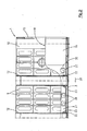
- eine Außenansicht eines erfindungsgemäßen Sickerblocks gemäß einem ersten Ausführungsbeispiel,
- Fig. 2
- einen Teil eines Mittel-Längs-Schnitts durch die untere Hälfte eines Sickerblocks gemäß Fig. 1,
- Fig. 3
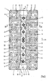
- einen mittigen Horizontalschnitt durch den Sickerblock gemäß Fig. 1,
- Fig. 4
- einen Teil-Querschnitt gemäß der Schnittlinie IV-IV in Fig. 3,
- Fig. 5
- einen Fig. 3 entsprechenden Schnitt eines Sickerblocks gemäß einem zweiten Ausführungsbeispiel,
- Fig. 6
- einen Teil-Querschnitt gemäß der Schnittlinie VI-VI in Fig. 5,
- Fig. 7
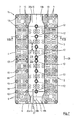
- einen Fig. 3 entsprechenden Schnitt eines Sickerblocks gemäß einem dritten Ausführungsbeispiel und
- Fig. 8
- einen Teil-Querschnitt gemäß der Schnittlinie VIII-VIII in Fig. 7.
- Fig. 1
- an external view of a filter block according to the invention according to a first embodiment,
- Fig. 2
- a portion of a central longitudinal section through the lower half of a percolator block according to FIG. 1,
- Fig. 3
- a central horizontal section through the percolation block according to FIG. 1,
- Fig. 4
- a partial cross section along the section line IV-IV in Fig. 3,
- Fig. 5
- a section corresponding to FIG. 3 of a percolation block according to a second embodiment,
- Fig. 6
- a partial cross section along the section line VI-VI in Fig. 5,
- Fig. 7
- a Fig. 3 corresponding section of a percolation block according to a third embodiment and
- Fig. 8
- a partial cross section according to the section line VIII-VIII in Fig. 7.
Im Folgenden wird unter Bezugnahme auf die Fig. 1 bis 4 ein erstes Ausführungsbeispiel der Erfindung beschrieben. Ein auch als Rigolenfüllkörper bezeichneter Sickerblock 1 wird zur Regenwasserbewirtschaftung im Erdreich verwendet. Häufig werden mehrere Sickerblöcke 1 miteinander verbunden, nebeneinander, übereinander oder fluchtend hintereinander angeordnet. Hierzu werden spezifische Verbindungselemente verwendet, die nicht dargestellt sind.Hereinafter, a first embodiment of the invention will be described with reference to Figs. Also known as Rigolenfüllkörper Sickerblock 1 is used for rainwater management in the soil. Frequently, several leach blocks 1 are connected to each other, arranged side by side, one above the other or in alignment. For this purpose, specific fasteners are used, which are not shown.
Der Sickerblock 1 ist in seiner Grundstruktur bekannt und am Markt verfügbar. Er weist ein im Wesentlichen quaderförmiges Gehäuse 2 auf, bestehend aus einer rechteckigen Grundplatte 3, von dieser nach oben vorstehenden, jeweils zueinander parallelen, einander gegenüberliegenden Längs-Seitenwänden 4, 5 und Stirn-Seitenwänden 6, 7, sowie einer mit den Seitenwänden 4, 5, 6 und 7 verbundenen Deckplatte 8. Die Grundplatte 3, die Deckplatte 8 sowie die Seitenwände 4, 5, 6 und 7 weisen über ihre ganze Oberfläche verteilt zahlreiche schlitzförmige Durchtritts-Öffnungen 9 auf, die einen Durchtritt von Wasser in das bzw. aus dem Gehäuse 2 ermöglichen.The Sickerblock 1 is known in its basic structure and available on the market. It has a substantially
Zwischen der Grundplatte 3 und der Deckplatte 8 sind zahlreiche vertikale, hohlzylinderförmige, zur Abstützung dienende Säulen 10 angeordnet. Diese sind auf den Kreuzungspunkten eines rechtwinkligen kartesischen Gitters angeordnet. Die Säulen 10 sind bezüglich einer mittig zwischen den Seitenwänden 4, 5 und senkrecht zur Grundplatte 3 verlaufenden Mittel-Längs-Ebene 11 spiegelsymmetrisch angeordnet, wobei die mittleren Säulen 12 mittig in der Mittel-Längs-Ebene 11 liegen. Im vorliegenden Fall sind neben der Längs-Reihe mittlerer Säulen 12 auf beiden Seiten der Mittel-Längs-Ebene 11 noch zwei Längs-Reihen von Säulen 10 angeordnet. Die Säulen 10 sind auch spiegelsymmetrisch bezüglich einer mittig zwischen den Seitenwänden 6, 7 und senkrecht zur Grundplatte 3 verlaufenden Mittel-Quer-Ebene 13 angeordnet. Die bezüglich der Mittel-Quer-Ebene 13 mittleren Säulen 10 liegen nicht in der Ebene 13, sondern unmittelbar benachbart zu beiden Seiten derselben. Zusätzlich sind auf beiden Seiten der Ebene vier weitere Quer-Reihen von Säulen 10 vorgesehen. Insgesamt befinden sich die Säulen 10, 12 auf fünf parallel zur Ebene 11 verlaufenden Längs-Reihen und auf zehn parallel zur Ebene 13 verlaufenden Quer-Reihen. Grundsätzlich ist auch eine andere Zahl von Säulen 10 bzw. von Quer-Reihen oder Längs-Reihen möglich. Die Säulen 10 können auch in anderer Form angeordnet sein, wobei eine symmetrische Anordnung, gegebenenfalls mit einer anderen Symmetrie, besonders stabil ist. Die umfangsseitig äußeren Säulen 10, d. h. die den Seitenwänden 4, 5, 6 und 7 nächsten Säulen 10 sind als Teil der Seitenwände 4, 5, 6 und 7 ausgebildet. Die Seitenwände 4, 5, 6 und 7 werden also durch die außenliegenden Säulen 10 sowie dazwischenliegende, mit diesen verbundene Wand-Elemente 14 gebildet, in denen die oben erwähnten Durchtritts-Öffnungen 9 angeordnet sind.Between the
In der jeweils unteren Hälfte der Seitenwände 6, 7 ist mittig bezüglich der Ebene 11 eine im Folgenden als Inspektions-Öffnung 15 bezeichnete Öffnung zum Anschluss eines Entwässerungs-Rohrs vorgesehen. Über den jeweiligen Inspektions-Öffnungen 15 befindet sich umgeben von einem Ringsteg 16 ein kreisförmiger Deckel 17, der zur Bildung einer der Inspektions-Öffnung 15 entsprechenden Öffnung ausgebrochen werden kann. Der Sickerblock 1 entspricht, soweit bisher beschrieben, dem Stand der Technik.In the respective lower half of the
In den Sickerblock 1 ist eine nach oben offene, die gegenüberliegenden Inspektions-Öffnungen 15 verbindende, flache, muldenförmige, eine an sich geschlossene Führungsfläche bildende Führungs-Rinne 18 eingesetzt. Die Führungs-Rinne 18 besteht ausgehend von der jeweiligen Inspektions-Öffnung 15 aus einem Anschluss-Abschnitt 19, einem sich daran anschlie-ßenden Übergangs-Abschnitt 20 sowie einem zwischen den Übergangs-Abschnitten 20 liegenden Mittel-Abschnitt 21. Die Führungs-Rinne 18 ist spiegelsymmetrisch bezüglich der Mittel-Längs-Ebene 11 ausgebildet. Sie ist von oben auf die Längs-Reihe der mittleren Säulen 12 aufgeschoben, wobei die Führungs-Rinne 18 hierzu mittige Öffnungen 22 aufweist, die die zugehörigen Säulen 12 aufnehmen. Im Bereich der Öffnungen 22 weist die Führungs-Rinne 18 nach oben vorstehende, an den Säulen 12 anliegende Ringstege 23 auf. Die Öffnungen 22 sind primär im Bereich des Mittel-Abschnitts 21, jedoch nicht im Bereich der Anschluss-Abschnitte 19 vorgesehen. Im Bereich der Anschluss-Abschnitte 19 ist die ansonsten dem Gitter entsprechende Säule 10 ausgespart. Die Führungs-Rinne 18 weist auf ihrer Unterseite einen Sockel 24 auf, der gegenüber der Grundplatte 3 abgestützt ist. Die Führungs-Rinne 18 ist im Bereich des Anschluss-Abschnitts 19 höher gezogen als im Bereich des Mittel-Abschnitts 21. Der Anschluss-Abschnitt 19 hat im Wesentlichen im Querschnitt die Form eines Halbkreises. Der Mittel-Abschnitt 21 liegt ebenfalls auf einem Kreisbogen, besitzt jedoch nur 20 bis 25% der Höhe des Anschluss-Abschnitts 19. Im Bereich des Übergangs-Abschnitts 20 geht die Rinne vom Anschluss-Abschnitt 19 kontinuierlich in den Mittel-Abschnitt 21 über. Die Führungs-Rinne 18 begrenzt im unteren Bereich einen die Inspektions-Öffnungen 15 verbindenden Inspektions-Kanal 25, der abgesehen von der Führungs-Rinne 18 keine unmittelbare Längs-Begrenzung besitzt. Der Inspektions-Kanal 25 kann als gedankliche Verbindung der Ränder der einander gegenüberliegenden Inspektions-Öffnungen 15 angesehen werden. Mittig in dem Inspektions-Kanal 25 befinden sich die mittleren Säulen 12. Die Führungs-Rinne 18 weist symmetrisch bezüglich der Mittel-Längs-Ebene 11 Durchbrüche 26 auf, die mit einer Inspektions-Sonde 27 eine Inspektion des hinter der Führungs-Rinne 18 befindlichen Bereichs senkrecht zur Mittel-Längs-Ebene 11 ermöglichen. Durch diese Durchbrüche 26 kann im Bedarfsfall der Sickerblock 1 auch gespült werden. Die Durchbrüche 26 sind in regelmäßigen Abständen, insbesondere paarweise, angeordnet.In the Sickerblock 1 is an upwardly open, the
Bei einer Inspektion wird eine Inspektions-Sonde 27 und danach gegebenenfalls eine Spüllanze durch eine Inspektions-Öffnung 15 in den Sickerblock 1 eingeschoben. Die Führungs-Rinne 18 führt bei einer Verschiebung der Inspektions-Sonde 27 entlang einer Längs-Richtung 28 die Sonde 27. Die Breite der Führungs-Rinne 18 ist so gewählt, dass die Sonde 27 entweder links oder rechts von den mittleren Säulen 12 vorbeigeschoben werden kann. Der Anschluss des Anschluss-Abschnitts 19 an die Inspektions-Öffnung 15 ist stufenlos ausgebildet, so dass sowohl der Eintritt der Inspektions-Sonde 27 in den Sickerblock 1 als auch der Austritt aus dem Sickerblock 1 stufenfrei und damit reibungslos möglich ist. Die Durchbrüche 26 ermöglichen eine Inspektion der hinter der Führungs-Rinne 18 liegenden Bereiche und gegebenenfalls eine Reinigung derselben mit einer Spüllanze. Durch die Beibehaltung der symmetrischen Geometrie der Säulen 10 beeinträchtigt der Inspektions-Kanal 25 die Stabilität des Sickerblocks 1 nicht. Es können mehrere fluchtend hintereinander angeordnete, durch Rohre bzw. Sickerblockverbinder miteinander verbundene Sickerblöcke 1 mit einer Inspektions-Sonde 27 in Folge inspiziert werden.During an inspection, an
Im Folgenden wird unter Bezugnahme auf die Fig. 5 und 6 ein zweites Ausführungsbeispiel der Erfindung beschrieben. Konstruktiv identische Teile erhalten dieselben Bezugszeichen wie beim ersten Ausführungsbeispiel, auf dessen Beschreibung hiermit verwiesen wird. Konstruktiv unterschiedliche, jedoch funktionell gleichartige Teile erhalten dieselben Bezugszeichen mit einem nachgestellten a. Der wesentliche Unterschied gegenüber dem ersten Ausführungsbeispiel besteht in der Ausgestaltung und insbesondere in der Positionierung der Führungs-Rinne 18a. Wie beim ersten Ausführungsbeispiel befindet sich der Anschluss-Abschnitt 19a bezüglich der Mittel-Längs-Ebene 11 mittig und fluchtend hinter den Inspektions-Öffnungen 15. Der Mittel-Abschnitt 21a verläuft jedoch nicht spiegelsymmetrisch bezüglich der Mittel-Längs-Achse 11, sondern exzentrisch, im vorliegenden in Fig. 5 dargestellten Fall links von der Mittel-Längs-Ebene 11. Der Mittel-Abschnitt 21a verläuft zwischen der mittleren Längs-reihe der Säulen 12 und der sich links daran anschließenden nächsten Längs-Reihe von Säulen 10. Auf der der Mittel-Längs-Ebene 11 abgewandten Seite verläuft der Mittel-Abschnitt 21a linear. Auf der der Mittel-Längs-Ebene 11 zugewandten Seite weist der Mittel-Abschnitt 21 a halbzylinderförmige Ausnehmungen 22a auf, die sich an die mittleren Säulen 12 anschmiegen. Auf die Weise kann der Raum zwischen der mittleren Längs-Reihe und der sich daran anschließenden nächsten Längs-Reihe von Säulen 10, 12 optimal genutzt werden. Die Übergangs-Abschnitte 20a schaffen eine kontinuierliche, glatte Verbindung zwischen dem Anschluss-Abschnitt 19a und dem Mittel-Abschnitt 21 a, so dass die Inspektions-Sonde 27 störungsfrei vom Anschluss-Abschnitt 19a in den Mittel-Abschnitt 21a geleitet wird. Wie bei dem ersten Ausführungsbeispiel sind Durchbrüche 26 vorgesehen, die dieselbe Funktion haben. Der Anschluss-Abschnitt 19a ist nur geringfügig höher als der Mittel-Abschnitt 21a, wie dies aus Fig. 6 ersichtlich ist. Vorteilhaft an der Anordnung der Rinne 18a ist, dass diese keine Hindernisse in Form von Säulen 12 aufweist.Hereinafter, a second embodiment of the invention will be described with reference to FIGS. 5 and 6. Structurally identical parts receive the same reference numerals as in the first embodiment, to the description of which reference is hereby made. Structurally different, but functionally similar parts receive the same reference numerals with a trailing a. The essential difference with respect to the first exemplary embodiment lies in the design and in particular in the positioning of the
Im Folgenden wird unter Bezugnahme auf die Fig. 7 und 8 ein drittes Ausführungsbeispiel der Erfindung beschrieben. Identische Teile erhalten dieselben Bezugszeichen wie beim ersten Ausführungsbeispiel, auf dessen Beschreibung hiermit verwiesen wird. Konstruktiv unterschiedliche, jedoch funktionell gleichartige Teile erhalten dieselben Bezugszeichen mit einem nachgestellten b. Der wesentliche Unterschied gegenüber dem ersten Ausführungsbeispiel besteht in der Ausgestaltung des Mittel-Abschnitts 21b. Die Führungs-Rinne 18b mit ihren Abschnitten 19b, 20b und 21b ist spiegelsymmetrisch bezüglich der Mittel-Längs-Ebene 11 ausgebildet. Die Anschluss-Abschnitte 19b haben dieselbe Form wie beim ersten Ausführungsbeispiel. Der Mittel-Abschnitt 21b ist jedoch nicht wie beim ersten oder zweiten Ausführungsbeispiel einläufig, sondern doppelläufig. Er weist im Querschnitt die Form einer nach oben offenen liegenden Zahl 3 oder liegenden halben 8 oder eines ω (kleines Omega) auf. Mittig weist der Mittel-Abschnitt 21b Öffnungen 22b auf, die durch die Säulen 12 geführt sind. Der Mittel-Abschnitt 21b erstreckt sich von der Mittel-Längs-Ebene 11 senkrecht zu dieser in beide Richtungen bis vor die jeweils angrenzende nächste Längs-Reihe von Säulen 10. Vorteilhaft an dieser Anordnung ist, dass die Inspektions-Sonde 27 links oder rechts von den Säulen 12 an diesen vorbei geführt werden kann. Durch die Form einer liegenden Zahl 3 wird sichergestellt, dass es zu keinen Kollisionen zwischen der Inspektions-Sonde 27 und den Säulen 12 kommt. Ein weiterer Vorteil der symmetrischen Ausgestaltung der Führungs-Rinne 18b besteht darin, dass sich bei der Verbindung von mehreren Sickerblöcken 1b hintereinander für die Inspektions-Sonde 27 immer ein gerader Kanal ergibt.Hereinafter, a third embodiment of the invention will be described with reference to FIGS. 7 and 8. Identical parts are given the same reference numerals as in the first embodiment, on the Description is hereby incorporated. Structurally different, but functionally similar parts receive the same reference numerals with a trailing b. The essential difference from the first embodiment is the design of the
Claims (10)
Priority Applications (5)
| Application Number | Priority Date | Filing Date | Title |
|---|---|---|---|
| PL06003472T PL1820914T3 (en) | 2006-02-21 | 2006-02-21 | Irrigation device |
| DK06003472T DK1820914T3 (en) | 2006-02-21 | 2006-02-21 | Irrigation |
| EP06003472A EP1820914B1 (en) | 2006-02-21 | 2006-02-21 | Irrigation device |
| DE502006003436T DE502006003436D1 (en) | 2006-02-21 | 2006-02-21 | Sickerblock |
| AT06003472T ATE428830T1 (en) | 2006-02-21 | 2006-02-21 | LEAKAGE BLOCK |
Applications Claiming Priority (1)
| Application Number | Priority Date | Filing Date | Title |
|---|---|---|---|
| EP06003472A EP1820914B1 (en) | 2006-02-21 | 2006-02-21 | Irrigation device |
Publications (2)
| Publication Number | Publication Date |
|---|---|
| EP1820914A1 true EP1820914A1 (en) | 2007-08-22 |
| EP1820914B1 EP1820914B1 (en) | 2009-04-15 |
Family
ID=36808602
Family Applications (1)
| Application Number | Title | Priority Date | Filing Date |
|---|---|---|---|
| EP06003472A Not-in-force EP1820914B1 (en) | 2006-02-21 | 2006-02-21 | Irrigation device |
Country Status (5)
| Country | Link |
|---|---|
| EP (1) | EP1820914B1 (en) |
| AT (1) | ATE428830T1 (en) |
| DE (1) | DE502006003436D1 (en) |
| DK (1) | DK1820914T3 (en) |
| PL (1) | PL1820914T3 (en) |
Cited By (8)
| Publication number | Priority date | Publication date | Assignee | Title |
|---|---|---|---|---|
| EP2148016A1 (en) | 2008-07-25 | 2010-01-27 | Ralph-Peter Dr.-Ing. Hegler | Triple-dig unit |
| DE102009004914A1 (en) * | 2009-01-16 | 2010-07-22 | Rehau Ag + Co. | Versickerbox for a rigging system |
| US8292117B2 (en) | 2008-04-02 | 2012-10-23 | Aliaxis Participations | Stackable water holding tank |
| EP2568090A1 (en) * | 2011-09-09 | 2013-03-13 | Dakota Italia S.p.A. | Sump |
| DE102012105057A1 (en) | 2011-09-16 | 2013-03-21 | Voda Cz S.R.O. | Rainwater drainage device installed in parking lot, has closure caps that are provided at upper surfaces of perforated hollow sections which are connected with each other through connection structure |
| CN107366341A (en) * | 2016-05-13 | 2017-11-21 | 蔡宜真 | Water resource integrates construction method |
| WO2017217853A1 (en) * | 2016-06-17 | 2017-12-21 | Pipelife Nederland B.V. | Box for water storage having lamellar panels |
| EP3626895A1 (en) * | 2018-09-18 | 2020-03-25 | Philipp Heitker | Irrigation body for the production of underground rain water storage |
Citations (1)
| Publication number | Priority date | Publication date | Assignee | Title |
|---|---|---|---|---|
| DE202005010090U1 (en) * | 2005-06-24 | 2005-09-22 | Hauraton Betonwarenfabrik Gmbh & Co Kg | Drainage element for percolating surface water comprises column elements spaced and arranged in rows |
-
2006
- 2006-02-21 AT AT06003472T patent/ATE428830T1/en active
- 2006-02-21 DE DE502006003436T patent/DE502006003436D1/en active Active
- 2006-02-21 DK DK06003472T patent/DK1820914T3/en active
- 2006-02-21 PL PL06003472T patent/PL1820914T3/en unknown
- 2006-02-21 EP EP06003472A patent/EP1820914B1/en not_active Not-in-force
Patent Citations (1)
| Publication number | Priority date | Publication date | Assignee | Title |
|---|---|---|---|---|
| DE202005010090U1 (en) * | 2005-06-24 | 2005-09-22 | Hauraton Betonwarenfabrik Gmbh & Co Kg | Drainage element for percolating surface water comprises column elements spaced and arranged in rows |
Cited By (9)
| Publication number | Priority date | Publication date | Assignee | Title |
|---|---|---|---|---|
| US8292117B2 (en) | 2008-04-02 | 2012-10-23 | Aliaxis Participations | Stackable water holding tank |
| EP2148016A1 (en) | 2008-07-25 | 2010-01-27 | Ralph-Peter Dr.-Ing. Hegler | Triple-dig unit |
| DE102009004914A1 (en) * | 2009-01-16 | 2010-07-22 | Rehau Ag + Co. | Versickerbox for a rigging system |
| EP2568090A1 (en) * | 2011-09-09 | 2013-03-13 | Dakota Italia S.p.A. | Sump |
| DE102012105057A1 (en) | 2011-09-16 | 2013-03-21 | Voda Cz S.R.O. | Rainwater drainage device installed in parking lot, has closure caps that are provided at upper surfaces of perforated hollow sections which are connected with each other through connection structure |
| CN107366341A (en) * | 2016-05-13 | 2017-11-21 | 蔡宜真 | Water resource integrates construction method |
| WO2017217853A1 (en) * | 2016-06-17 | 2017-12-21 | Pipelife Nederland B.V. | Box for water storage having lamellar panels |
| NL2016991A (en) * | 2016-06-17 | 2017-12-21 | Pipelife Nederland Bv | Box for water storage having lamellar panels |
| EP3626895A1 (en) * | 2018-09-18 | 2020-03-25 | Philipp Heitker | Irrigation body for the production of underground rain water storage |
Also Published As
| Publication number | Publication date |
|---|---|
| DK1820914T3 (en) | 2009-08-10 |
| PL1820914T3 (en) | 2009-07-31 |
| DE502006003436D1 (en) | 2009-05-28 |
| EP1820914B1 (en) | 2009-04-15 |
| ATE428830T1 (en) | 2009-05-15 |
Similar Documents
| Publication | Publication Date | Title |
|---|---|---|
| EP1820914B1 (en) | Irrigation device | |
| EP0343192B1 (en) | Stud link for energy supply chains | |
| DE3434999C2 (en) | Support grid for a suspended ceiling | |
| DE102009044412A1 (en) | trench body | |
| EP0282622A1 (en) | Pluggable connector for contacting directly a printed circuit board | |
| DE4322535C2 (en) | Electrical terminals with pluggable cross bridges | |
| DE202020106300U1 (en) | Concrete molding insert | |
| DD250266A5 (en) | HOLDER FRAME FOR CATALYST PLATE | |
| DE2917046B2 (en) | Crossbar distributors for telecommunications, in particular telephone systems | |
| DE202014008401U1 (en) | Mounting plate for a surface heating and cooling system | |
| DE2425451B2 (en) | Pile connection | |
| DE2846552A1 (en) | DISTRIBUTION BLOCK FOR ELECTRICAL LINES | |
| DE8021868U1 (en) | CARRIER HORDE FOR SEMICONDUCTOR DISCS | |
| DE2926780C2 (en) | Formwork panel | |
| DE102011011656A1 (en) | Brick system for building e.g. vertical wall, has stone with bar deeply immersed in slot of elevation of another stone so that lower side of former stone lies on upper side of latter stone, and recess cover surface supported by support bar | |
| EP3641129A1 (en) | Assembly method for mounting a modular assembly structure and in particular for assembling photovoltaic installations | |
| DE2342866C2 (en) | Component system for the construction of switchboards | |
| DE2751744C2 (en) | Device for holding a tube bundle | |
| DE102004056005B4 (en) | Ventilation grille for loading and / or venting a room | |
| DE60026134T2 (en) | Metal grid for covering sewage channels | |
| EP3526490B1 (en) | Chain link for an energy guiding chain | |
| DE551934C (en) | Frame for fastening a large number of auxiliary electrical lines in a switchgear | |
| EP0202418A2 (en) | Frame portion for a contact element strip of a plug connection | |
| DE102021126349A1 (en) | Modular frame for mounting solar modules at an angle to a set-up surface | |
| DE102004025333B4 (en) | Stacks connecting device, has corrugated plastic foils with interconnecting parts having projecting units, which are provided with openings that align with one another for accommodating locking rod, which passes through foils |
Legal Events
| Date | Code | Title | Description |
|---|---|---|---|
| PUAI | Public reference made under article 153(3) epc to a published international application that has entered the european phase |
Free format text: ORIGINAL CODE: 0009012 |
|
| AK | Designated contracting states |
Kind code of ref document: A1 Designated state(s): AT BE BG CH CY CZ DE DK EE ES FI FR GB GR HU IE IS IT LI LT LU LV MC NL PL PT RO SE SI SK TR |
|
| AX | Request for extension of the european patent |
Extension state: AL BA HR MK YU |
|
| 17P | Request for examination filed |
Effective date: 20080129 |
|
| 17Q | First examination report despatched |
Effective date: 20080228 |
|
| AKX | Designation fees paid |
Designated state(s): AT BE BG CH CY CZ DE DK EE ES FI FR GB GR HU IE IS IT LI LT LU LV MC NL PL PT RO SE SI SK TR |
|
| GRAP | Despatch of communication of intention to grant a patent |
Free format text: ORIGINAL CODE: EPIDOSNIGR1 |
|
| GRAS | Grant fee paid |
Free format text: ORIGINAL CODE: EPIDOSNIGR3 |
|
| GRAA | (expected) grant |
Free format text: ORIGINAL CODE: 0009210 |
|
| AK | Designated contracting states |
Kind code of ref document: B1 Designated state(s): AT BE BG CH CY CZ DE DK EE ES FI FR GB GR HU IE IS IT LI LT LU LV MC NL PL PT RO SE SI SK TR |
|
| REG | Reference to a national code |
Ref country code: CH Ref legal event code: EP Ref country code: GB Ref legal event code: FG4D Free format text: NOT ENGLISH |
|
| REG | Reference to a national code |
Ref country code: IE Ref legal event code: FG4D |
|
| REF | Corresponds to: |
Ref document number: 502006003436 Country of ref document: DE Date of ref document: 20090528 Kind code of ref document: P |
|
| REG | Reference to a national code |
Ref country code: PL Ref legal event code: T3 |
|
| REG | Reference to a national code |
Ref country code: DK Ref legal event code: T3 |
|
| NLV1 | Nl: lapsed or annulled due to failure to fulfill the requirements of art. 29p and 29m of the patents act | ||
| PG25 | Lapsed in a contracting state [announced via postgrant information from national office to epo] |
Ref country code: PT Free format text: LAPSE BECAUSE OF FAILURE TO SUBMIT A TRANSLATION OF THE DESCRIPTION OR TO PAY THE FEE WITHIN THE PRESCRIBED TIME-LIMIT Effective date: 20090915 Ref country code: FI Free format text: LAPSE BECAUSE OF FAILURE TO SUBMIT A TRANSLATION OF THE DESCRIPTION OR TO PAY THE FEE WITHIN THE PRESCRIBED TIME-LIMIT Effective date: 20090415 Ref country code: ES Free format text: LAPSE BECAUSE OF FAILURE TO SUBMIT A TRANSLATION OF THE DESCRIPTION OR TO PAY THE FEE WITHIN THE PRESCRIBED TIME-LIMIT Effective date: 20090726 Ref country code: LT Free format text: LAPSE BECAUSE OF FAILURE TO SUBMIT A TRANSLATION OF THE DESCRIPTION OR TO PAY THE FEE WITHIN THE PRESCRIBED TIME-LIMIT Effective date: 20090415 |
|
| PG25 | Lapsed in a contracting state [announced via postgrant information from national office to epo] |
Ref country code: IS Free format text: LAPSE BECAUSE OF FAILURE TO SUBMIT A TRANSLATION OF THE DESCRIPTION OR TO PAY THE FEE WITHIN THE PRESCRIBED TIME-LIMIT Effective date: 20090815 Ref country code: SI Free format text: LAPSE BECAUSE OF FAILURE TO SUBMIT A TRANSLATION OF THE DESCRIPTION OR TO PAY THE FEE WITHIN THE PRESCRIBED TIME-LIMIT Effective date: 20090415 Ref country code: LV Free format text: LAPSE BECAUSE OF FAILURE TO SUBMIT A TRANSLATION OF THE DESCRIPTION OR TO PAY THE FEE WITHIN THE PRESCRIBED TIME-LIMIT Effective date: 20090415 Ref country code: SE Free format text: LAPSE BECAUSE OF FAILURE TO SUBMIT A TRANSLATION OF THE DESCRIPTION OR TO PAY THE FEE WITHIN THE PRESCRIBED TIME-LIMIT Effective date: 20090715 Ref country code: NL Free format text: LAPSE BECAUSE OF FAILURE TO SUBMIT A TRANSLATION OF THE DESCRIPTION OR TO PAY THE FEE WITHIN THE PRESCRIBED TIME-LIMIT Effective date: 20090415 |
|
| REG | Reference to a national code |
Ref country code: IE Ref legal event code: FD4D |
|
| PG25 | Lapsed in a contracting state [announced via postgrant information from national office to epo] |
Ref country code: RO Free format text: LAPSE BECAUSE OF FAILURE TO SUBMIT A TRANSLATION OF THE DESCRIPTION OR TO PAY THE FEE WITHIN THE PRESCRIBED TIME-LIMIT Effective date: 20090415 Ref country code: EE Free format text: LAPSE BECAUSE OF FAILURE TO SUBMIT A TRANSLATION OF THE DESCRIPTION OR TO PAY THE FEE WITHIN THE PRESCRIBED TIME-LIMIT Effective date: 20090415 Ref country code: IE Free format text: LAPSE BECAUSE OF FAILURE TO SUBMIT A TRANSLATION OF THE DESCRIPTION OR TO PAY THE FEE WITHIN THE PRESCRIBED TIME-LIMIT Effective date: 20090415 |
|
| PLBE | No opposition filed within time limit |
Free format text: ORIGINAL CODE: 0009261 |
|
| STAA | Information on the status of an ep patent application or granted ep patent |
Free format text: STATUS: NO OPPOSITION FILED WITHIN TIME LIMIT |
|
| PG25 | Lapsed in a contracting state [announced via postgrant information from national office to epo] |
Ref country code: SK Free format text: LAPSE BECAUSE OF FAILURE TO SUBMIT A TRANSLATION OF THE DESCRIPTION OR TO PAY THE FEE WITHIN THE PRESCRIBED TIME-LIMIT Effective date: 20090415 |
|
| 26N | No opposition filed |
Effective date: 20100118 |
|
| PG25 | Lapsed in a contracting state [announced via postgrant information from national office to epo] |
Ref country code: BG Free format text: LAPSE BECAUSE OF FAILURE TO SUBMIT A TRANSLATION OF THE DESCRIPTION OR TO PAY THE FEE WITHIN THE PRESCRIBED TIME-LIMIT Effective date: 20090715 |
|
| PGFP | Annual fee paid to national office [announced via postgrant information from national office to epo] |
Ref country code: DK Payment date: 20100222 Year of fee payment: 5 |
|
| REG | Reference to a national code |
Ref country code: CH Ref legal event code: PL |
|
| GBPC | Gb: european patent ceased through non-payment of renewal fee |
Effective date: 20100221 |
|
| PG25 | Lapsed in a contracting state [announced via postgrant information from national office to epo] |
Ref country code: GR Free format text: LAPSE BECAUSE OF FAILURE TO SUBMIT A TRANSLATION OF THE DESCRIPTION OR TO PAY THE FEE WITHIN THE PRESCRIBED TIME-LIMIT Effective date: 20090716 Ref country code: MC Free format text: LAPSE BECAUSE OF NON-PAYMENT OF DUE FEES Effective date: 20100301 Ref country code: CH Free format text: LAPSE BECAUSE OF NON-PAYMENT OF DUE FEES Effective date: 20100228 Ref country code: LI Free format text: LAPSE BECAUSE OF NON-PAYMENT OF DUE FEES Effective date: 20100228 |
|
| PG25 | Lapsed in a contracting state [announced via postgrant information from national office to epo] |
Ref country code: IT Free format text: LAPSE BECAUSE OF FAILURE TO SUBMIT A TRANSLATION OF THE DESCRIPTION OR TO PAY THE FEE WITHIN THE PRESCRIBED TIME-LIMIT Effective date: 20090415 Ref country code: GB Free format text: LAPSE BECAUSE OF NON-PAYMENT OF DUE FEES Effective date: 20100221 |
|
| PGFP | Annual fee paid to national office [announced via postgrant information from national office to epo] |
Ref country code: PL Payment date: 20110119 Year of fee payment: 6 Ref country code: CZ Payment date: 20110209 Year of fee payment: 6 |
|
| REG | Reference to a national code |
Ref country code: DK Ref legal event code: EBP |
|
| PGFP | Annual fee paid to national office [announced via postgrant information from national office to epo] |
Ref country code: FR Payment date: 20120228 Year of fee payment: 7 |
|
| PGFP | Annual fee paid to national office [announced via postgrant information from national office to epo] |
Ref country code: BE Payment date: 20120221 Year of fee payment: 7 |
|
| PG25 | Lapsed in a contracting state [announced via postgrant information from national office to epo] |
Ref country code: CY Free format text: LAPSE BECAUSE OF FAILURE TO SUBMIT A TRANSLATION OF THE DESCRIPTION OR TO PAY THE FEE WITHIN THE PRESCRIBED TIME-LIMIT Effective date: 20090415 |
|
| PG25 | Lapsed in a contracting state [announced via postgrant information from national office to epo] |
Ref country code: HU Free format text: LAPSE BECAUSE OF FAILURE TO SUBMIT A TRANSLATION OF THE DESCRIPTION OR TO PAY THE FEE WITHIN THE PRESCRIBED TIME-LIMIT Effective date: 20091016 Ref country code: LU Free format text: LAPSE BECAUSE OF NON-PAYMENT OF DUE FEES Effective date: 20100221 |
|
| PG25 | Lapsed in a contracting state [announced via postgrant information from national office to epo] |
Ref country code: TR Free format text: LAPSE BECAUSE OF FAILURE TO SUBMIT A TRANSLATION OF THE DESCRIPTION OR TO PAY THE FEE WITHIN THE PRESCRIBED TIME-LIMIT Effective date: 20090415 |
|
| PGFP | Annual fee paid to national office [announced via postgrant information from national office to epo] |
Ref country code: AT Payment date: 20120126 Year of fee payment: 7 |
|
| BERE | Be: lapsed |
Owner name: HEGLER, RALPH-PETER, DR.-ING. Effective date: 20130228 |
|
| REG | Reference to a national code |
Ref country code: AT Ref legal event code: MM01 Ref document number: 428830 Country of ref document: AT Kind code of ref document: T Effective date: 20130228 |
|
| PG25 | Lapsed in a contracting state [announced via postgrant information from national office to epo] |
Ref country code: CZ Free format text: LAPSE BECAUSE OF NON-PAYMENT OF DUE FEES Effective date: 20130221 Ref country code: AT Free format text: LAPSE BECAUSE OF NON-PAYMENT OF DUE FEES Effective date: 20130228 |
|
| REG | Reference to a national code |
Ref country code: FR Ref legal event code: ST Effective date: 20131031 |
|
| PG25 | Lapsed in a contracting state [announced via postgrant information from national office to epo] |
Ref country code: FR Free format text: LAPSE BECAUSE OF NON-PAYMENT OF DUE FEES Effective date: 20130228 Ref country code: BE Free format text: LAPSE BECAUSE OF NON-PAYMENT OF DUE FEES Effective date: 20130228 |
|
| PG25 | Lapsed in a contracting state [announced via postgrant information from national office to epo] |
Ref country code: PL Free format text: LAPSE BECAUSE OF NON-PAYMENT OF DUE FEES Effective date: 20130221 |
|
| REG | Reference to a national code |
Ref country code: PL Ref legal event code: LAPE |
|
| PGFP | Annual fee paid to national office [announced via postgrant information from national office to epo] |
Ref country code: DE Payment date: 20140424 Year of fee payment: 9 |
|
| REG | Reference to a national code |
Ref country code: DE Ref legal event code: R119 Ref document number: 502006003436 Country of ref document: DE |
|
| PG25 | Lapsed in a contracting state [announced via postgrant information from national office to epo] |
Ref country code: DE Free format text: LAPSE BECAUSE OF NON-PAYMENT OF DUE FEES Effective date: 20150901 |