EP1820725A2 - Bicycle shifter - Google Patents
Bicycle shifter Download PDFInfo
- Publication number
- EP1820725A2 EP1820725A2 EP07001074A EP07001074A EP1820725A2 EP 1820725 A2 EP1820725 A2 EP 1820725A2 EP 07001074 A EP07001074 A EP 07001074A EP 07001074 A EP07001074 A EP 07001074A EP 1820725 A2 EP1820725 A2 EP 1820725A2
- Authority
- EP
- European Patent Office
- Prior art keywords
- shifter
- mounting bracket
- main
- bicycle
- shifter body
- Prior art date
- Legal status (The legal status is an assumption and is not a legal conclusion. Google has not performed a legal analysis and makes no representation as to the accuracy of the status listed.)
- Granted
Links
Images




Classifications
-
- B—PERFORMING OPERATIONS; TRANSPORTING
- B62—LAND VEHICLES FOR TRAVELLING OTHERWISE THAN ON RAILS
- B62M—RIDER PROPULSION OF WHEELED VEHICLES OR SLEDGES; POWERED PROPULSION OF SLEDGES OR SINGLE-TRACK CYCLES; TRANSMISSIONS SPECIALLY ADAPTED FOR SUCH VEHICLES
- B62M25/00—Actuators for gearing speed-change mechanisms specially adapted for cycles
- B62M25/02—Actuators for gearing speed-change mechanisms specially adapted for cycles with mechanical transmitting systems, e.g. cables, levers
- B62M25/04—Actuators for gearing speed-change mechanisms specially adapted for cycles with mechanical transmitting systems, e.g. cables, levers hand actuated
-
- B—PERFORMING OPERATIONS; TRANSPORTING
- B62—LAND VEHICLES FOR TRAVELLING OTHERWISE THAN ON RAILS
- B62K—CYCLES; CYCLE FRAMES; CYCLE STEERING DEVICES; RIDER-OPERATED TERMINAL CONTROLS SPECIALLY ADAPTED FOR CYCLES; CYCLE AXLE SUSPENSIONS; CYCLE SIDECARS, FORECARS, OR THE LIKE
- B62K23/00—Rider-operated controls specially adapted for cycles, i.e. means for initiating control operations, e.g. levers, grips
- B62K23/02—Rider-operated controls specially adapted for cycles, i.e. means for initiating control operations, e.g. levers, grips hand actuated
- B62K23/06—Levers
-
- Y—GENERAL TAGGING OF NEW TECHNOLOGICAL DEVELOPMENTS; GENERAL TAGGING OF CROSS-SECTIONAL TECHNOLOGIES SPANNING OVER SEVERAL SECTIONS OF THE IPC; TECHNICAL SUBJECTS COVERED BY FORMER USPC CROSS-REFERENCE ART COLLECTIONS [XRACs] AND DIGESTS
- Y10—TECHNICAL SUBJECTS COVERED BY FORMER USPC
- Y10T—TECHNICAL SUBJECTS COVERED BY FORMER US CLASSIFICATION
- Y10T74/00—Machine element or mechanism
- Y10T74/20—Control lever and linkage systems
- Y10T74/20207—Multiple controlling elements for single controlled element
- Y10T74/20256—Steering and controls assemblies
- Y10T74/20268—Reciprocating control elements
- Y10T74/2028—Handle bar type
- Y10T74/20287—Flexible control element
-
- Y—GENERAL TAGGING OF NEW TECHNOLOGICAL DEVELOPMENTS; GENERAL TAGGING OF CROSS-SECTIONAL TECHNOLOGIES SPANNING OVER SEVERAL SECTIONS OF THE IPC; TECHNICAL SUBJECTS COVERED BY FORMER USPC CROSS-REFERENCE ART COLLECTIONS [XRACs] AND DIGESTS
- Y10—TECHNICAL SUBJECTS COVERED BY FORMER USPC
- Y10T—TECHNICAL SUBJECTS COVERED BY FORMER US CLASSIFICATION
- Y10T74/00—Machine element or mechanism
- Y10T74/20—Control lever and linkage systems
- Y10T74/20396—Hand operated
- Y10T74/20402—Flexible transmitter [e.g., Bowden cable]
- Y10T74/2042—Flexible transmitter [e.g., Bowden cable] and hand operator
- Y10T74/20438—Single rotatable lever [e.g., for bicycle brake or derailleur]
-
- Y—GENERAL TAGGING OF NEW TECHNOLOGICAL DEVELOPMENTS; GENERAL TAGGING OF CROSS-SECTIONAL TECHNOLOGIES SPANNING OVER SEVERAL SECTIONS OF THE IPC; TECHNICAL SUBJECTS COVERED BY FORMER USPC CROSS-REFERENCE ART COLLECTIONS [XRACs] AND DIGESTS
- Y10—TECHNICAL SUBJECTS COVERED BY FORMER USPC
- Y10T—TECHNICAL SUBJECTS COVERED BY FORMER US CLASSIFICATION
- Y10T74/00—Machine element or mechanism
- Y10T74/20—Control lever and linkage systems
- Y10T74/20576—Elements
- Y10T74/20732—Handles
- Y10T74/2078—Handle bars
- Y10T74/20822—Attachments and accessories
Definitions
- This invention generally relates to a bicycle shifter. More specifically, the present invention relates to a bicycle shifter that is mounted on a bicycle and that is used to shift the gears of a bicycle.
- Bicycling is becoming an increasingly more popular form of recreation as well as a means of transportation. Moreover, bicycling has become a very popular competitive sport for both amateurs and professionals. Whether the bicycle is used for recreation, transportation or competition, the bicycle industry is constantly improving the various components of the bicycle. One component that has been extensively redesigned is the shifter of the bicycle.
- a shifter of a bicycle is typically linked to a shifting device by a Bowden shifting cable, for example.
- the shifting device is made to shift the gears by operating an operating member in the form of a lever, for example, on the shifter.
- a conventional shifter has a bracket mounted on a handlebar, and a main shifter body mounted on the mounting bracket.
- the shifter is attached to the handlebars inside a bracket on the brake lever. If the shifter is attached to the handlebar within the brake lever, then the shifter may be difficult to operate, depending on the shapes of the operating member(s) of the shifter.
- the mounting bracket is divided into two members: a boss part mounted on the handlebar, and a fixing member for fixing the boss in place on the handlebar.
- the fixing member is a cylindrical member having a large hole into which the boss part fits, a small hole into which the handlebar fits, and a slot formed in the axial direction.
- the fixing member is provided with a fixing bolt for making the slot narrow.
- the fixing member is fixed in place on the handlebar.
- the boss part is then also fixed in place on the handlebar.
- the position where the main shifter body is attached can be varied in relation to the boss part and set to an arbitrary position in the axial direction of the handlebar. This can be achieved by varying the position where the boss part fits in the large hole in the axial direction.
- the fixing bolt of the fixing member must be loosened to vary the position where the main shifter body is attached.
- the alignment of the fixing member on the mounting bracket sometimes changes because the fixing member is capable of rotating in relation to the boss part. Therefore, the alignment of the main shifter body around the axis of the handlebar also changes. Since the alignment of the main shifter body also changes when the attachment position of the main shifter body is varied, the alignment of the main shifter body must be adjusted, and such position alignment is troublesome.
- One object of the present invention is to provide a bicycle shifter that can be easily attached to the bicycle in an adjustable manner.
- a bicycle shifter that basically comprises a bracket, a main shifter body, and a fixing mechanism in accordance with a first aspect of the present invention.
- the mounting bracket is configured to be fixedly coupled to a bicycle.
- the main shifter body includes a shifter mechanism disposed within an interior of the main shifter body.
- the fixing mechanism fixes the main shifter body and the mounting bracket together in a predetermined relative angular orientation.
- the main shifter body is adjustable relative to the mounting bracket by the fixing mechanism such that the main shifter body is selectively retainable in a plurality of different attachment positions relative to the mounting bracket between at least a first position and a second position without completely detaching the main shifter body from the mounting bracket and while maintaining the predetermined relative angular orientation.
- the main shifter body when the attachment position of the main shifter body is varied, the main shifter body can be attached at an arbitrary position between the first position and the second position by the fixing mechanism. Since the design allows for the attachment position of the main shifter body to be varied in relation to the mounting bracket by the fixing mechanism, and set to an arbitrary position between the first position and the second position, the alignment (the predetermined relative angular orientation) of the main shifter body does not change when the attachment position of the main shifter body is varied. Therefore, the position where the main shifter body is attached to the bicycle can be easily varied.
- the bicycle shifter of the first aspect of the present invention is provided such that the mounting bracket is configured to be fixedly coupled on a handlebar of the bicycle, and the first and second positions are disposed along a path that is generally parallel to a longitudinal direction of the handlebar.
- the mounting bracket can be disposed on either the interior or exterior of a brake lever mounted on the handlebar.
- the bicycle shifter of the second aspect of the present invention is provided such that the fixing mechanism comprises: an elongated slot formed in one of the mounting bracket and the main shifter body, and that extends in the longitudinal direction; at least one female threaded part formed in one of the mounting bracket and the main shifter body; and a bolt passing through the slot and screwed into the female threaded part.
- the main shifter body can be fixed in place by passing the bolt through the slot and screwing the bolt into the female threaded part, and the main shifter body can be fixed in place at an arbitrary attachment position between the first position and the second position at either end of the slot by shifting the attachment position in the longitudinal direction of the slot.
- the bicycle shifter of the third aspect of the present invention is provided such that the fixing mechanism further includes a rotation-stopping mechanism for stopping the main shifter body from rotating relative to the mounting bracket.
- the main shifter body does not rotate and can maintain its alignment even if the main shifter body is fixed in place with only one bolt.
- the bicycle shifter of the fourth aspect of the present invention is provided such that the rotation-stopping mechanism comprises: a plurality of rotation-stopping protrusions on one of the mounting bracket and the main shifter body; and a plurality of rotation-stopping recesses on the other of the mounting bracket and the main shifter body that are interlock with the rotation-stopping protrusions to stop the main shifter body from rotating relative to the mounting bracket.
- the main shifter body can be stopped from rotating and can be guided in the longitudinal direction as a result of the recesses and protrusions fitting together.
- the bicycle shifter of any one of the third through fifth aspects of the present invention is further provided with a loosening-prevention member linking the mounting bracket and the main shifter body to prevent the main shifter body from coming loose from the mounting bracket.
- the main shifter body does not come loose from the mounting bracket even when the fixed attachment of the fixing mechanism is released.
- a bicycle shifter is basically provided with a bracket, a main shifter body and a fixing mechanism.
- the mounting bracket is configured to be fixedly coupled to a bicycle.
- the main shifter body includes a shifter mechanism disposed within an interior of the main shifter body, the shifter mechanism including a shift positioning member configured to rotate around a shaft member.
- the fixing mechanism fixes the main shifter body and the mounting bracket together in a predetermined relative angular orientation by a fixing member that is attached to the shaft member such that the main shifter body is selectively retainable in a plurality of different attachment positions relative to the mounting bracket between a first end position and a second end position while maintaining the predetermined relative angular orientation.
- the main shifter body when the attachment position of the main shifter body is varied, the main shifter body can be attached to the mounting bracket at least at a first position and a second position by means of the fixing mechanism. Since the position where the main shifter body is attached in relation to the mounting bracket can be varied between a first position and a second position by securing the fixing member to the shaft member, the alignment of the main shifter body does not change when the attachment position of the main shifter body is varied. Therefore, the position where the main shifter body is attached on the bicycle can be easily varied. Moreover, the structure of the fixing mechanism is simplified because normally the attachment is secured by using the shaft member, which is used as the primary shaft of the shifter mechanism.
- the bicycle shifter the seventh aspect of the present invention is provided such that the shaft member includes a female threaded part at the distal end, and the fixing member includes a first bolt that is screwed into the female threaded part.
- the main shifter body can easily be fixed in place in a manner that allows its position to be varied. This is achieved by screwing the first bolt into the female threaded part of the shaft member.
- the bicycle shifter of the eighth aspect of the present invention is provided such that the fixing member further includes a second bolt that is screwed into a female threaded part of the main shifter body but not into the shaft member.
- the fixing member further includes a second bolt that is screwed into a female threaded part of the main shifter body but not into the shaft member.
- the design allows for the attachment position of the main shifter body in relation to the mounting bracket to be varied by the fixing mechanism to an arbitrary position between the first position and the second position, and the alignment of the main shifter body therefore does not change when the attachment position of the main shifter body is varied. Accordingly, the position where the main shifter body is attached to the bicycle can be easily varied.
- the alignment of the main shifter body does not change when the attachment position of the main shifter body is varied. This is because the position where the main shifter body is attached in relation to the mounting bracket can be varied between a first position and a second position by means of a fixing member that is fitted over the shaft member. Therefore, the position where the main shifter body is attached to the bicycle can be easily varied. Moreover, the fixing structure is simplified because normally the attachment is secured by using the shaft member, which is used as the primary shaft of the shifter mechanism.
- Figure 1 is a right side elevational view of a bicycle using a pair of bicycle shifters in accordance with a first embodiment of the present invention
- Figure 2 is a rear perspective view of a rear shifter unit in accordance with the first embodiment of the present invention
- FIG. 3 is a top plan view of the rear shifter unit in accordance with the first embodiment of the present invention.
- FIG. 4 is a side elevational view of the rear shifter unit in accordance with the first embodiment of the present invention.
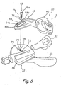
- FIG. 5 is an exploded perspective view of the rear shifter unit in accordance with the first embodiment of the present invention.
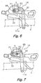
- Figure 6 is a top plan view of the rear shifter unit with the main shifter body fixed in place at the first position;
- Figure 7 is a top plan view of the rear shifter unit with the main shifter body fixed in place at the second position;
- Figure 8 is an exploded perspective view, similar to Figure 5, of a rear shifter unit in accordance with a second embodiment of the present invention.
- Figure 9 is a partial cross-sectional view of the fixing mechanism for the rear shifter unit in accordance with the second embodiment of the present invention.
- Figure 10 is a partial cross-sectional view, similar to Figure 9, of a fixing mechanism for a rear shifter unit in accordance with a third embodiment of the present invention.
- Figure 11 is an exploded perspective view, similar to Figure 5, of a rear shifter unit in accordance with a modification of the third embodiment of the present invention.
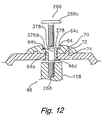
- Figure 12 is a partial cross-sectional view, similar to Figure 9, of the fixing mechanism for the rear shifter unit in accordance with the modification of the third embodiment of the present invention.
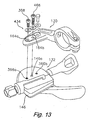
- Figure 13 is an exploded perspective view, similar to Figure 5, of a rear shifter unit in accordance with a fourth embodiment of the present invention.
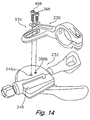
- Figure 14 an exploded perspective view, similar to Figure 5, of a rear shifter unit in accordance with a fifth embodiment of the present invention.
- the bicycle 1 includes a frame 2 which has a suspension fork 3 and a handlebar 4 fixed in place at the top of the suspension fork 3.
- the handlebar 4 has a pair of (rear and front) brake levers 11 and 12 mounted thereon, and a pair of (front and rear) shifter units 15 and 16 mounted thereon.
- the front and rear shifter units 15 and 16 are disposed near the brake levers 12 and 11, respectively, on the inside of the brake levers 12 and 11 on the handlebar 4.
- the front shifter unit 15 and the rear shifter unit 16 are mirror-images, since their configurations and operations are identical, except for the number of gearshift positions.
- the rear shifter unit 16 has more gearshift positions than the front shifter unit 15. Thus, only the rear shifter unit 16 will be described in the following description in detail.
- a front derailleur 17 constitutes an external shifting device that is mounted in the middle of the frame 2.
- a rear derailleur 18 constitutes an external shifting device that is mounted at the back end of the frame 2.
- the front derailleur 17 is disposed below a seat tube 2b of the frame 2, for example, and guides a chain 23 onto any one of three sprockets of a front chain wheel 19a, for example.
- the rear derailleur 18 is disposed at the back end of a chain stay 2c of the frame 2, and guides the chain 23 onto any one of eight sprockets of a rear chain wheel 19b, for example.
- the front derailleur 17 and the rear derailleur 18 are linked to front and rear shifter units (examples of shifters) 15 and 16 via front and rear shifting cables 25 and 26.
- the rear shifter unit 16 basically includes a bracket 30, a main shifter body 32 and a fixing mechanism 34.
- the bracket 30 is configured and arranged to be fixed in place on the handlebar 4 on the inside of a brake bracket 11 a of the front brake lever 11.
- the main shifter body 32 is mounted on the mounting bracket 30.
- the fixing mechanism 34 is configured and arranged for fixing the main shifter body 32 in place on the mounting bracket 30, as shown in Figures 2 through 4.
- the mounting bracket basically includes a band clamp 40, a clamping bolt 41 and an attachment arm 42.
- the band clamp 40 is fixed in place on the handlebar 4.
- the attachment arm 42 extends from the band clamp 40 and curves inward (to the left in Figure 2) at the middle.
- the band clamp 40 defines an handlebar attachment hole 40a through which the handlebar 4 runs.
- a slit 40b is formed in the periphery of the band clamp 40 in the radial direction relative to the attachment hole 40a so that the band clamp 40 can be squeezed to change the diameter of the attachment hole 40a.
- the band clamp 40 has first and second clamping parts 40c and 40d formed on opposite sides of the slit 40b.
- the first and second clamping parts 40c and 40d protrude generally in the radial direction relative to the attachment hole 40a.
- the band clamp 40 is fixed in place on the handlebar 4 by tightening the clamping bolt 41 that spans across the slit 40b and runs through both of the clamping parts 40c and 40d, so that the slit 40b is narrowed.
- the main shifter body 32 has a shifter housing 46 and a shifter mechanism 48.
- the housing 46 is fixed in place on the mounting bracket 30.
- the shifter mechanism 48 is mounted inside the housing 46.
- the housing 46 is provided with an outer securing part 50 in which an outer casing 44a of a shifting cable 44 is secured.
- the shifter mechanism 48 has a winding body 52 and a positioning mechanism 56.
- the winding body 52 is configured and arranged for winding an inner wire 44b of the shifting cable 44.
- the positioning mechanism 56 includes a positioning member 54 for positioning the winding body 52 at a shifting position.
- the winding body 52 and the positioning member 54 are supported by a shaft member 58 that is supported in the housing 46, and rotate around the shaft member 58.
- the shifter mechanism 48 also has a winding lever 60 and a release lever 62.
- the winding lever 60 is configured and arranged for rotating the positioning member 54 in the cable winding direction by an amount equivalent to one or more shifting positions.
- the release lever 62 is configured and arranged for rotating the positioning member in the direction of releasing the inner wire 44b of the shifting cable 44.
- the levers 60 and 62 are pivotally mounted on the housing 46 so as to be turn.
- the release lever 62 is configured and arranged to release the inner wire 44b of the shifting cable 44 by turning the release lever 62
- the fixing mechanism 34 is capable of fixing the main shifter body 32 in place at an arbitrary attachment position between a first position P1 and a second position P2 disposed along the longitudinal direction (to the left and right in Figure 3) of the handlebar 4, as shown in Figure 3. Specifically, the fixing mechanism 34 is capable of varying the attachment position of the main shifter body 32 in the longitudinal direction without completely detaching the main shifter body 32 from the mounting bracket 30 and while maintaining the predetermined relative angular orientation of the main shifter body 32 relative to the mounting bracket 30.
- the distance S between the first position P1 and the second position P2 is preferably greater than the width of the brake bracket 11 a (about 10 to 30 mm, for example). In the first embodiment, this distance S is about 15 mm.
- the fixing mechanism 34 has a slot 64 extending in the longitudinal direction in the distal end of the attachment arm 42 of the mounting bracket 30, a female threaded part 66 formed at the top surface of the housing 46 of the main shifter body 32, and a bolt 68 that is passed through the slot 64 and screwed into the female threaded part 66, as shown in Figure 5.
- the slot 64 has an oval-shaped first slot 64a formed in the longitudinal direction, and a second slot 64b that is wider than the first slot.
- the female threaded part 66 is disposed above the shaft member 58 in the first embodiment.
- the female threaded part 66 may also be formed at a location other than above the shaft member 58.
- the bolt 68 is a bolt that is provided with a hexagonal hole and has a head 68a in which the hexagonal hole is formed, and the head 68a is disposed in a step 64c between the first slot 64a and the second slot 64b via a washer 76. Therefore, in the first embodiment, the head 68a is disposed in the second slot 64b, and the head 68a is kept from protruding from the attachment arm 42.
- the fixing mechanism 34 further comprises a rotation-stopping mechanism 70 for stopping the main shifter body 32 from rotating relative to the mounting bracket 30.
- the rotation-stopping mechanism 70 has a pair of rotation-stopping protrusions 72 formed on the top surface of the housing 46 of the main shifter body 32, and a pair of rotation-stopping recesses 74 that are provided on the underside of the attachment arm 42 of the mounting bracket 30.
- the rotation-stopping protrusions 72 are oval shapes in the longitudinal direction.
- the rotation-stopping recesses 74 are elongated, oval shapes that extend in a longitudinal direction of the oval shapes longer than the rotation-stopping protrusions 72.
- the main shifter body 32 can be fixed in place on the mounting bracket 30 by firmly screwing the bolt 68 into the female threaded part 66. If the bolt 68 is tightened when the main shifter body 32 is fixed in place, the main shifter body 32 is guided by the rotation-stopping mechanism 70 and can move between the first position P1 shown in Figure 6 and the second position P2 shown in Figure 7 in the longitudinal direction in relation to the mounting bracket 30. If the bolt 68 is firmly screwed in after the main shifter body 32 is moved to the appropriate position, the main shifter body 32 can be fixed in place at an arbitrary attachment position between the first position P1 and the second position P2 in relation to the mounting bracket 30.
- the main shifter body 32 can be fixed in place at an appropriate position near the second position P2 in cases in which the mounting bracket 30 is attached on the inside of the brake bracket 11a, and the main shifter body 32 can be fixed in place at an appropriate position near the first position P1 in cases in which the mounting bracket 30 is attached on the outside of the brake bracket 11a.
- this attachment position is adjusted, the alignment or predetermined relative angular orientation of the main shifter body 32 does not change even if the attachment position of the main shifter body 32 is varied. Therefore, the position where the main shifter body 32 is attached on the handlebar 4 can be easily varied.
- a fixing mechanism 134 is provided with a loosening-prevention member 178 that links the mounting bracket 30 to the main shifter body 32 in order to prevent a main shifter body 132 from coming loose when a bolt 168 is removed, as shown in Figures 8 and 9.
- the fixing mechanism 134 basically includes the slot 64 of the mounting bracket 30 (discussed above), a loosening-prevention member 178 with a female threaded part 166, and a bolt 168 that is screwed into the female threaded part 166.
- the bolt 168 has a larger head 168a than in the first embodiment, i.e., a head whose diameter is greater than the width of the second slot 64b. Therefore, in the second embodiment, the head 168a of the bolt 168 is secured in the top surface 64d of the attachment arm 42.
- the loosening-prevention member 178 is cylindrical and can be inserted via a through-hole 46a formed in the housing 46.
- the female threaded part 166 is formed in this cylinder of the loosening-prevention member 178.
- the bolt 168 is screwed into the female threaded part 166 of the loosening-prevention member 178.
- a flange 178a formed so as to be capable of moving in the longitudinal direction of the first slot 64a and to catch on the step 64c.
- the loosening-prevention member 178 is secured on the inner walls of the housing 46 by crimping in a manner such that the other end passes through the first slot 64a and protrudes slightly from the through-hole 46a of the housing 46, as shown in Figure 9.
- the method of fixing the loosening-prevention member 178 is not limited to crimping, and adhesion, bonding, welding, or another suitable method can also be used.
- the bolt 168 is screwed into the female threaded part 166 and fixed in place at an arbitrary position.
- the head 168a of the bolt 168 is secured into the top surface 64d of the attachment arm 42, unlike in the first embodiment.
- the main shifter body 32 is thereby fixed in place in the mounting bracket 30.
- the shifter in accordance with this third embodiment includes the shifter mechanism 48 of the first embodiment with the winding body 52 and the positioning member 54 of the positioning mechanism 56. However, the positioning member 54 for positioning the winding body 52 are supported by a shaft member 158.
- a loosening-prevention member 278 of a fixing mechanism 234 is cylindrical in shape and can be inserted via a through-hole 46a formed in the housing 46.
- a retaining ring 278c which is formed so as to be capable of moving in the longitudinal direction of the first slot 64a and to catch on the step 64c, is located at one end (the top in Figure 10) of the loosening-prevention member 278.
- a flange 278a is located around the periphery of the through-hole 46a.
- the flange 278a contacts the inner periphery of the housing 46.
- a through-hole 278b is formed to allow a bolt 268 to be passed through.
- the loosening-prevention member 278 is mounted by being run via the through-hole 46a and the first slot 64a from the inside of the housing 46, and is secured on the step 64c by the retaining ring 278c.
- a female threaded part 266 is formed in the top surface of a shaft member 158 of the shifter mechanism 48, and the bolt 268 is passed via the through-hole 278b and screwed into the female threaded part 266. Therefore, the screw length of the bolt 268 is greater than in the first and second embodiments.
- the bolt 268 is passed through the loosening-prevention member 278, and the loosening-prevention member 278 can therefore be arranged in a more compact manner than in cases in which the bolt and the loosening-prevention member are arranged separately.
- a loosening-prevention member 378 of a fixing mechanism 334 is cylindrical and has oval-shaped flanges 378a and 378b at either end.
- the housing 46 and the mounting bracket 30 can be coupled and released by rotating the loosening-prevention member 378 by 90 degrees between an inserted position (solid lines in Figure 11) at which the member is inserted through the first slot 64a, and a fitted position (double-dashed lines in Figure 11) at which the member is fitted onto the flange 378a and cannot move in the axial direction of the bolt 268.
- An oval-shaped insertion hole 46d is formed in the housing 46, allowing for insertion of the flange 378b disposed in an inserted configuration.
- the mounting bracket 30 is placed on the housing 46 of the main shifter body 32 in a state in which the first slot 64a is aligned with the insertion hole 46d.
- the loosening-prevention member 378 is inserted through the first slot 64a and the insertion hole 46d in an inserted configuration, and the loosening-prevention member 378 is rotated by 90 degrees to the fitted position while the flange 378b is inserted through the insertion hole 46d.
- a small screw 378d is screwed in until the distal end reaches the step 64c, and the fitted position is achieved.
- the flanges 378a and 378b are thereby interlocked with the step 64c and with the inner walls of the housing 46, the housing 46 is linked with the mounting bracket 30, and the main shifter body 32 is prevented from coming loose.
- the main shifter body 32 can be fixed in place on the mounting bracket 30 at an arbitrary position between the first position P 1 and the second position P2. This is achieved by screwing the bolt 268 into the female threaded part 266 formed in the shaft member 158.
- the shifter in accordance with this fourth embodiment includes the shifter mechanism 48 of the first embodiment with the winding body 52 and the positioning member 54 of the positioning mechanism 56.
- the positioning member 54 for positioning the winding body 52 are supported by the shaft member 158 of the third embodiment shown in Figure 12.
- a slot was formed in the mounting bracket 30 in the fixing mechanism.
- a fixing mechanism 434 is to form at least one through-hole (two through-holes 164a and 164b are used in Figure 13) in a bracket 130 and to provide the same number of female threaded parts (two female threaded parts 366a and 366b are used in Figure 13) as the number of through-holes 164a an d 164b in the top surface of the housing 146 of the main shifter body 132. Then, fix the screws in place using the female threaded part 266 of the shaft member 158 shown in Figure 12.
- a through-hole 146a is formed in the housing 146 above the female threaded part 266.
- the bolt 368 screwed into the female threaded part 366a or 366b need not be passed through the housing 146 and is therefore shorter in length than the bolt 468 screwed into the female threaded part 266.
- the main shifter body 132 is fixed in place at the first attachment position by inserting the bolt 368 via the through-hole 164a, and screwing it into the female threaded part 366a, and also by inserting the bolt 468 via the through-hole 164b and screwing it into the female threaded part 266 via the through-hole 146a. Also, the main shifter body 132 is fixed in place at the second attachment position by inserting the bolt 468 via the through-hole 164a and screwing it into the female threaded part 266 via the through-hole 146a, and by inserting the bolt 368 via the through-hole 164b and screwing it into the female threaded part 366b.
- the main shifter body 132 can be selectively retainable in at least first and second attachment positions relative to the mounting bracket 130 in the same predetermined relative angular orientation, but with the main shifter body 132 offset longitudinally relative to the mounting bracket 130.
- the fixing mechanism 434 fixes the main shifter body 132 and the mounting bracket 130 together in a predetermined relative angular orientation.
- the main shifter body 132 is adjustable relative to the mounting bracket 130 by the bolt 368 being selectively screwed into one of the female threaded parts 366a and 366b and with the bolt 468 being screwed into the female threaded part 266 such that the main shifter body 132 is selectively retainable in at least first and second attachment positions relative to the mounting bracket 130 in the predetermined relative angular orientation.
- the fixing mechanism 434 includes a plurality of fixing members (the bolts 368 and 468) coupled between the main shifter body 132 and the mounting bracket 132 in a first attachment arrangement to obtain the first attachment position and in a second attachment arrangement to obtain the second attachment position.
- the alignment of the main shifter body 132 does not change when the attachment position of the main shifter body 132 is varied. Therefore, the position where the main shifter body 132 is attached to the handlebar 4 can be easily varied.
- this attachment is secured by using the shaft member 158, which functions as the primary shaft of the shifter mechanism, and the structure of the fixing mechanism 434 can therefore be simplified. Also, since the attachment is secured with multiple bolts, the strength of the attachment is increased, and the rotation-stopping mechanism is not needed; which simplifies the structure.
- a fixing mechanism 534 includes two bolt members 368 and 468, for example, that are used to fix a main shifter body 232 in place on a mounting bracket 230 which has a slot similar to the slot 64 of the first embodiment.
- a housing 246 is provided with a through-hole 246a and a female threaded part 366b, which are disposed above a female threaded part 266 of a shaft member 158 in the same manner as in Figure 12.
- an arbitrary attachment position can be selected between the first end attachment position and the second end attachment position by tightening the bolt members 368 and 468. Also, since the attachment is secured with multiple bolt members, the strength of the attachment is increased, and there is no need for a rotation-stopping mechanism.
- bolts were used as fixing members, but the fixing members are not limited to bolts, and nuts, elastic interlocking mechanisms, and other fixing members can be used.
- the rotation-stopping protrusions 72 were oval-shaped, but they do not necessarily need to be oval-shaped and can protrude in rectangular or circular shapes. Also, the rotation-stopping protrusions 72 can be formed on the mounting bracket 30, and the rotation-stopping recesses 74 can be formed in the housing 46 of the main shifter body 32.
- the slots were formed in the mounting brackets, and the female threaded parts were formed in the main shifter body, but another possibility is to form the slots in the main shifter body, and the female threaded parts in the mounting bracket.
- the present invention was described using the rear shifter unit as an example, but the present invention can also be applied to the front shifter unit.
- a handlebar was given as an example of the position where the shifter unit could be attached, but as long as the shifter unit can be operated manually, it can be attached at any location on the bicycle, such as the down tube.
- the term “configured” as used herein to describe a component, section or part of a device includes hardware and/or software that is constructed and/or programmed to carry out the desired function.
- the term “comprising” and its derivatives, as used herein are intended to be open ended terms that specify the presence of the stated features, elements, components, groups, integers, and/or steps, but do not exclude the presence of other unstated features, elements, components, groups, integers and/or steps.
- the foregoing also applies to words having similar meanings such as the terms, “including”, “having” and their derivatives.
- the terms "part,” “section,” “portion,” “member” or “element” when used in the singular can have the dual meaning of a single part or a plurality of parts.
- the following directional terms “forward, rearward, above, downward, vertical, horizontal, below and transverse” as well as any other similar directional terms refer to those directions of a bicycle equipped with the present invention. Accordingly, these terms, as utilized to describe the present invention should be interpreted relative to a bicycle equipped with the present invention as used in the normal riding position.
- terms of degree such as “substantially”, “about” and “approximately” as used herein mean a reasonable amount of deviation of the modified term such that the end result is not significantly changed.
Landscapes
- Engineering & Computer Science (AREA)
- Mechanical Engineering (AREA)
- Chemical & Material Sciences (AREA)
- Combustion & Propulsion (AREA)
- Transportation (AREA)
- Steering Devices For Bicycles And Motorcycles (AREA)
Abstract
Description
- This invention generally relates to a bicycle shifter. More specifically, the present invention relates to a bicycle shifter that is mounted on a bicycle and that is used to shift the gears of a bicycle.
- Bicycling is becoming an increasingly more popular form of recreation as well as a means of transportation. Moreover, bicycling has become a very popular competitive sport for both amateurs and professionals. Whether the bicycle is used for recreation, transportation or competition, the bicycle industry is constantly improving the various components of the bicycle. One component that has been extensively redesigned is the shifter of the bicycle.
- A shifter of a bicycle is typically linked to a shifting device by a Bowden shifting cable, for example. The shifting device is made to shift the gears by operating an operating member in the form of a lever, for example, on the shifter. A conventional shifter has a bracket mounted on a handlebar, and a main shifter body mounted on the mounting bracket. In conventional practice, in cases in which a shifter is provided separately from a brake lever, normally, the shifter is attached to the handlebars inside a bracket on the brake lever. If the shifter is attached to the handlebar within the brake lever, then the shifter may be difficult to operate, depending on the shapes of the operating member(s) of the shifter.
- There are conventional shifters in which the main shifter body is capable of moving in relation to handlebar attachment part, and the position where the main shifter body is attached can be varied in the axial direction of the handlebar (see, for example,
Japanese Unexamined Utility Model Application No. 1-134591 - With the conventional configuration previously described, the fixing bolt of the fixing member must be loosened to vary the position where the main shifter body is attached. When the fixing bolt is loosened, the alignment of the fixing member on the mounting bracket sometimes changes because the fixing member is capable of rotating in relation to the boss part. Therefore, the alignment of the main shifter body around the axis of the handlebar also changes. Since the alignment of the main shifter body also changes when the attachment position of the main shifter body is varied, the alignment of the main shifter body must be adjusted, and such position alignment is troublesome.
- In view of the above, it will be apparent to those skilled in the art from this disclosure that there exists a need for an improved bicycle shifter. This invention addresses this need in the art as well as other needs, which will become apparent to those skilled in the art from this disclosure.
- One object of the present invention is to provide a bicycle shifter that can be easily attached to the bicycle in an adjustable manner.
- The foregoing objects can basically be attained by providing a bicycle shifter that basically comprises a bracket, a main shifter body, and a fixing mechanism in accordance with a first aspect of the present invention. The mounting bracket is configured to be fixedly coupled to a bicycle. The main shifter body includes a shifter mechanism disposed within an interior of the main shifter body. The fixing mechanism fixes the main shifter body and the mounting bracket together in a predetermined relative angular orientation. The main shifter body is adjustable relative to the mounting bracket by the fixing mechanism such that the main shifter body is selectively retainable in a plurality of different attachment positions relative to the mounting bracket between at least a first position and a second position without completely detaching the main shifter body from the mounting bracket and while maintaining the predetermined relative angular orientation.
- In this shifter, when the attachment position of the main shifter body is varied, the main shifter body can be attached at an arbitrary position between the first position and the second position by the fixing mechanism. Since the design allows for the attachment position of the main shifter body to be varied in relation to the mounting bracket by the fixing mechanism, and set to an arbitrary position between the first position and the second position, the alignment (the predetermined relative angular orientation) of the main shifter body does not change when the attachment position of the main shifter body is varied. Therefore, the position where the main shifter body is attached to the bicycle can be easily varied.
- According to a second aspect of the present invention, the bicycle shifter of the first aspect of the present invention is provided such that the mounting bracket is configured to be fixedly coupled on a handlebar of the bicycle, and the first and second positions are disposed along a path that is generally parallel to a longitudinal direction of the handlebar. In this case, the mounting bracket can be disposed on either the interior or exterior of a brake lever mounted on the handlebar.
- According to a third aspect of the present invention, the bicycle shifter of the second aspect of the present invention is provided such that the fixing mechanism comprises: an elongated slot formed in one of the mounting bracket and the main shifter body, and that extends in the longitudinal direction; at least one female threaded part formed in one of the mounting bracket and the main shifter body; and a bolt passing through the slot and screwed into the female threaded part. In this case, the main shifter body can be fixed in place by passing the bolt through the slot and screwing the bolt into the female threaded part, and the main shifter body can be fixed in place at an arbitrary attachment position between the first position and the second position at either end of the slot by shifting the attachment position in the longitudinal direction of the slot.
- According to a fourth aspect of the present invention, the bicycle shifter of the third aspect of the present invention is provided such that the fixing mechanism further includes a rotation-stopping mechanism for stopping the main shifter body from rotating relative to the mounting bracket. In this case, the main shifter body does not rotate and can maintain its alignment even if the main shifter body is fixed in place with only one bolt.
- According to a fifth aspect of the present invention, the bicycle shifter of the fourth aspect of the present invention is provided such that the rotation-stopping mechanism comprises: a plurality of rotation-stopping protrusions on one of the mounting bracket and the main shifter body; and a plurality of rotation-stopping recesses on the other of the mounting bracket and the main shifter body that are interlock with the rotation-stopping protrusions to stop the main shifter body from rotating relative to the mounting bracket. In this case, the main shifter body can be stopped from rotating and can be guided in the longitudinal direction as a result of the recesses and protrusions fitting together.
- According to a sixth aspect of the present invention, the bicycle shifter of any one of the third through fifth aspects of the present invention is further provided with a loosening-prevention member linking the mounting bracket and the main shifter body to prevent the main shifter body from coming loose from the mounting bracket. In this case, the main shifter body does not come loose from the mounting bracket even when the fixed attachment of the fixing mechanism is released.
- According to a seventh aspect of the present invention, a bicycle shifter is basically provided with a bracket, a main shifter body and a fixing mechanism. The mounting bracket is configured to be fixedly coupled to a bicycle. The main shifter body includes a shifter mechanism disposed within an interior of the main shifter body, the shifter mechanism including a shift positioning member configured to rotate around a shaft member. The fixing mechanism fixes the main shifter body and the mounting bracket together in a predetermined relative angular orientation by a fixing member that is attached to the shaft member such that the main shifter body is selectively retainable in a plurality of different attachment positions relative to the mounting bracket between a first end position and a second end position while maintaining the predetermined relative angular orientation. In this shifter, when the attachment position of the main shifter body is varied, the main shifter body can be attached to the mounting bracket at least at a first position and a second position by means of the fixing mechanism. Since the position where the main shifter body is attached in relation to the mounting bracket can be varied between a first position and a second position by securing the fixing member to the shaft member, the alignment of the main shifter body does not change when the attachment position of the main shifter body is varied. Therefore, the position where the main shifter body is attached on the bicycle can be easily varied. Moreover, the structure of the fixing mechanism is simplified because normally the attachment is secured by using the shaft member, which is used as the primary shaft of the shifter mechanism.
- According to an eighth aspect of the present invention, the bicycle shifter the seventh aspect of the present invention is provided such that the shaft member includes a female threaded part at the distal end, and the fixing member includes a first bolt that is screwed into the female threaded part. In this case, the main shifter body can easily be fixed in place in a manner that allows its position to be varied. This is achieved by screwing the first bolt into the female threaded part of the shaft member.
- According to a ninth: aspect of the present invention, the bicycle shifter of the eighth aspect of the present invention is provided such that the fixing member further includes a second bolt that is screwed into a female threaded part of the main shifter body but not into the shaft member. In this case, since the main shifter body is fixed in place by using two bolts, the strength of the attachment is increased and the main shifter body does not rotate.
- According to the present invention, the design allows for the attachment position of the main shifter body in relation to the mounting bracket to be varied by the fixing mechanism to an arbitrary position between the first position and the second position, and the alignment of the main shifter body therefore does not change when the attachment position of the main shifter body is varied. Accordingly, the position where the main shifter body is attached to the bicycle can be easily varied.
- According to the other inventions of the present invention, the alignment of the main shifter body does not change when the attachment position of the main shifter body is varied. This is because the position where the main shifter body is attached in relation to the mounting bracket can be varied between a first position and a second position by means of a fixing member that is fitted over the shaft member. Therefore, the position where the main shifter body is attached to the bicycle can be easily varied. Moreover, the fixing structure is simplified because normally the attachment is secured by using the shaft member, which is used as the primary shaft of the shifter mechanism.
- These and other objects, features, aspects and advantages of the present invention will become apparent to those skilled in the art from the following detailed description, which, taken in conjunction with the annexed drawings, discloses preferred embodiments of the present invention.
- Referring now to the attached drawings which form a part of this original disclosure:
- Figure 1 is a right side elevational view of a bicycle using a pair of bicycle shifters in accordance with a first embodiment of the present invention;
- Figure 2 is a rear perspective view of a rear shifter unit in accordance with the first embodiment of the present invention;
- Figure 3 is a top plan view of the rear shifter unit in accordance with the first embodiment of the present invention;
- Figure 4 is a side elevational view of the rear shifter unit in accordance with the first embodiment of the present invention;
- Figure 5 is an exploded perspective view of the rear shifter unit in accordance with the first embodiment of the present invention;
- Figure 6 is a top plan view of the rear shifter unit with the main shifter body fixed in place at the first position;
- Figure 7 is a top plan view of the rear shifter unit with the main shifter body fixed in place at the second position;
- Figure 8 is an exploded perspective view, similar to Figure 5, of a rear shifter unit in accordance with a second embodiment of the present invention;
- Figure 9 is a partial cross-sectional view of the fixing mechanism for the rear shifter unit in accordance with the second embodiment of the present invention;
- Figure 10 is a partial cross-sectional view, similar to Figure 9, of a fixing mechanism for a rear shifter unit in accordance with a third embodiment of the present invention;
- Figure 11 is an exploded perspective view, similar to Figure 5, of a rear shifter unit in accordance with a modification of the third embodiment of the present invention;
- Figure 12 is a partial cross-sectional view, similar to Figure 9, of the fixing mechanism for the rear shifter unit in accordance with the modification of the third embodiment of the present invention;
- Figure 13 is an exploded perspective view, similar to Figure 5, of a rear shifter unit in accordance with a fourth embodiment of the present invention; and
- Figure 14 an exploded perspective view, similar to Figure 5, of a rear shifter unit in accordance with a fifth embodiment of the present invention.
- Selected embodiments of the present invention will now be explained with reference to the drawings. It will be apparent to those skilled in the art from this disclosure that the following descriptions of the embodiments of the present invention are provided for illustration only and not for the purpose of limiting the invention as defined by the appended claims and their equivalents.
- Referring initially to Figure 1, a
bicycle 1 is illustrated that is equipped with the present invention. Thebicycle 1 includes a frame 2 which has asuspension fork 3 and ahandlebar 4 fixed in place at the top of thesuspension fork 3. Thehandlebar 4 has a pair of (rear and front) brake levers 11 and 12 mounted thereon, and a pair of (front and rear)shifter units rear shifter units handlebar 4. Thefront shifter unit 15 and therear shifter unit 16 are mirror-images, since their configurations and operations are identical, except for the number of gearshift positions. In particular, therear shifter unit 16 has more gearshift positions than thefront shifter unit 15. Thus, only therear shifter unit 16 will be described in the following description in detail. - A front derailleur 17 constitutes an external shifting device that is mounted in the middle of the frame 2. A
rear derailleur 18 constitutes an external shifting device that is mounted at the back end of the frame 2. The front derailleur 17 is disposed below aseat tube 2b of the frame 2, for example, and guides achain 23 onto any one of three sprockets of afront chain wheel 19a, for example. Therear derailleur 18 is disposed at the back end of a chain stay 2c of the frame 2, and guides thechain 23 onto any one of eight sprockets of arear chain wheel 19b, for example. The front derailleur 17 and therear derailleur 18 are linked to front and rear shifter units (examples of shifters) 15 and 16 via front andrear shifting cables - The
rear shifter unit 16 basically includes abracket 30, amain shifter body 32 and afixing mechanism 34. Thebracket 30 is configured and arranged to be fixed in place on thehandlebar 4 on the inside of abrake bracket 11 a of thefront brake lever 11. Themain shifter body 32 is mounted on the mountingbracket 30. The fixingmechanism 34 is configured and arranged for fixing themain shifter body 32 in place on the mountingbracket 30, as shown in Figures 2 through 4. - The mounting bracket basically includes a
band clamp 40, a clampingbolt 41 and anattachment arm 42. Theband clamp 40 is fixed in place on thehandlebar 4. Theattachment arm 42 extends from theband clamp 40 and curves inward (to the left in Figure 2) at the middle. Theband clamp 40 defines anhandlebar attachment hole 40a through which thehandlebar 4 runs. Aslit 40b is formed in the periphery of theband clamp 40 in the radial direction relative to theattachment hole 40a so that theband clamp 40 can be squeezed to change the diameter of theattachment hole 40a. Theband clamp 40 has first andsecond clamping parts slit 40b. The first andsecond clamping parts attachment hole 40a. Theband clamp 40 is fixed in place on thehandlebar 4 by tightening the clampingbolt 41 that spans across theslit 40b and runs through both of the clampingparts slit 40b is narrowed. - The
main shifter body 32 has ashifter housing 46 and ashifter mechanism 48. Thehousing 46 is fixed in place on the mountingbracket 30. Theshifter mechanism 48 is mounted inside thehousing 46. Thehousing 46 is provided with an outer securingpart 50 in which anouter casing 44a of a shiftingcable 44 is secured. - The
shifter mechanism 48 has a windingbody 52 and apositioning mechanism 56. The windingbody 52 is configured and arranged for winding aninner wire 44b of the shiftingcable 44. Thepositioning mechanism 56 includes a positioningmember 54 for positioning the windingbody 52 at a shifting position. The windingbody 52 and the positioningmember 54 are supported by ashaft member 58 that is supported in thehousing 46, and rotate around theshaft member 58. Theshifter mechanism 48 also has a windinglever 60 and arelease lever 62. The windinglever 60 is configured and arranged for rotating the positioningmember 54 in the cable winding direction by an amount equivalent to one or more shifting positions. Therelease lever 62 is configured and arranged for rotating the positioning member in the direction of releasing theinner wire 44b of the shiftingcable 44. Thelevers housing 46 so as to be turn. Therelease lever 62 is configured and arranged to release theinner wire 44b of the shiftingcable 44 by turning therelease lever 62 in either one of the two turning directions. - The fixing
mechanism 34 is capable of fixing themain shifter body 32 in place at an arbitrary attachment position between a first position P1 and a second position P2 disposed along the longitudinal direction (to the left and right in Figure 3) of thehandlebar 4, as shown in Figure 3. Specifically, the fixingmechanism 34 is capable of varying the attachment position of themain shifter body 32 in the longitudinal direction without completely detaching themain shifter body 32 from the mountingbracket 30 and while maintaining the predetermined relative angular orientation of themain shifter body 32 relative to the mountingbracket 30. The distance S between the first position P1 and the second position P2 is preferably greater than the width of thebrake bracket 11 a (about 10 to 30 mm, for example). In the first embodiment, this distance S is about 15 mm. - The fixing
mechanism 34. has aslot 64 extending in the longitudinal direction in the distal end of theattachment arm 42 of the mountingbracket 30, a female threadedpart 66 formed at the top surface of thehousing 46 of themain shifter body 32, and abolt 68 that is passed through theslot 64 and screwed into the female threadedpart 66, as shown in Figure 5. Theslot 64 has an oval-shapedfirst slot 64a formed in the longitudinal direction, and asecond slot 64b that is wider than the first slot. The female threadedpart 66 is disposed above theshaft member 58 in the first embodiment. The female threadedpart 66 may also be formed at a location other than above theshaft member 58. Thebolt 68 is a bolt that is provided with a hexagonal hole and has ahead 68a in which the hexagonal hole is formed, and thehead 68a is disposed in astep 64c between thefirst slot 64a and thesecond slot 64b via awasher 76. Therefore, in the first embodiment, thehead 68a is disposed in thesecond slot 64b, and thehead 68a is kept from protruding from theattachment arm 42. - The fixing
mechanism 34 further comprises a rotation-stoppingmechanism 70 for stopping themain shifter body 32 from rotating relative to the mountingbracket 30. The rotation-stoppingmechanism 70 has a pair of rotation-stoppingprotrusions 72 formed on the top surface of thehousing 46 of themain shifter body 32, and a pair of rotation-stoppingrecesses 74 that are provided on the underside of theattachment arm 42 of the mountingbracket 30. The rotation-stoppingprotrusions 72 are oval shapes in the longitudinal direction. The rotation-stoppingrecesses 74 are elongated, oval shapes that extend in a longitudinal direction of the oval shapes longer than the rotation-stoppingprotrusions 72. When thebracket 30 is fixed to themain shifter body 32 by the fixingmechanism 34, the rotation-stoppingrecesses 74 fit over the rotation-stoppingprotrusions 72 to stop themain shifter body 32 from rotating relative to thebracket 30, as shown in Figures 3 through 5. - In the
rear shifter unit 16 of the first embodiment, thus configured, themain shifter body 32 can be fixed in place on the mountingbracket 30 by firmly screwing thebolt 68 into the female threadedpart 66. If thebolt 68 is tightened when themain shifter body 32 is fixed in place, themain shifter body 32 is guided by the rotation-stoppingmechanism 70 and can move between the first position P1 shown in Figure 6 and the second position P2 shown in Figure 7 in the longitudinal direction in relation to the mountingbracket 30. If thebolt 68 is firmly screwed in after themain shifter body 32 is moved to the appropriate position, themain shifter body 32 can be fixed in place at an arbitrary attachment position between the first position P1 and the second position P2 in relation to the mountingbracket 30. For example, themain shifter body 32 can be fixed in place at an appropriate position near the second position P2 in cases in which the mountingbracket 30 is attached on the inside of thebrake bracket 11a, and themain shifter body 32 can be fixed in place at an appropriate position near the first position P1 in cases in which the mountingbracket 30 is attached on the outside of thebrake bracket 11a. Moreover, when this attachment position is adjusted, the alignment or predetermined relative angular orientation of themain shifter body 32 does not change even if the attachment position of themain shifter body 32 is varied. Therefore, the position where themain shifter body 32 is attached on thehandlebar 4 can be easily varied. - Referring now to Figures 8 and 9, a shifter in accordance with a second embodiment will now be explained. In view of the similarity between the first and second embodiments, the parts of the second embodiment that are identical to the parts of the first embodiment will be given the same reference numerals as the parts of the first embodiment. Moreover, the descriptions of the parts of the second embodiment that are identical to the parts of the first embodiment may be omitted for the sake of brevity.
- In a second embodiment, a
fixing mechanism 134 is provided with a loosening-prevention member 178 that links the mountingbracket 30 to themain shifter body 32 in order to prevent amain shifter body 132 from coming loose when abolt 168 is removed, as shown in Figures 8 and 9. - The
fixing mechanism 134 basically includes theslot 64 of the mounting bracket 30 (discussed above), a loosening-prevention member 178 with a female threadedpart 166, and abolt 168 that is screwed into the female threadedpart 166. Thebolt 168 has alarger head 168a than in the first embodiment, i.e., a head whose diameter is greater than the width of thesecond slot 64b. Therefore, in the second embodiment, thehead 168a of thebolt 168 is secured in thetop surface 64d of theattachment arm 42. - The loosening-
prevention member 178 is cylindrical and can be inserted via a through-hole 46a formed in thehousing 46. The female threadedpart 166 is formed in this cylinder of the loosening-prevention member 178. Thus, thebolt 168 is screwed into the female threadedpart 166 of the loosening-prevention member 178. At one end of the loosening-prevention member 178 (the top in Figure 9) is aflange 178a formed so as to be capable of moving in the longitudinal direction of thefirst slot 64a and to catch on thestep 64c. The loosening-prevention member 178 is secured on the inner walls of thehousing 46 by crimping in a manner such that the other end passes through thefirst slot 64a and protrudes slightly from the through-hole 46a of thehousing 46, as shown in Figure 9. As a result, when thebolt 168 is removed, themain shifter body 32 is not likely to come loose from the mountingbracket 30, because theflange 178a of the loosening-prevention member 178 catches on thestep 64c. The method of fixing the loosening-prevention member 178 is not limited to crimping, and adhesion, bonding, welding, or another suitable method can also be used. - In the second embodiment, when the
main shifter body 32 is fixed in place on the mountingbracket 30, thebolt 168 is screwed into the female threadedpart 166 and fixed in place at an arbitrary position. At this time, as previously described, thehead 168a of thebolt 168 is secured into thetop surface 64d of theattachment arm 42, unlike in the first embodiment. Themain shifter body 32 is thereby fixed in place in the mountingbracket 30. - Referring now to Figure 10, a shifter in accordance with a third embodiment will now be explained. In view of the similarity between the third embodiment and the prior embodiments, the parts of the third embodiment that are identical to the parts of the prior embodiments will be given the same reference numerals as the parts of the prior embodiments. Moreover, the descriptions of the parts of the third embodiment that are identical to the parts of the prior embodiments may be omitted for the sake of brevity.
- The shifter in accordance with this third embodiment includes the
shifter mechanism 48 of the first embodiment with the windingbody 52 and the positioningmember 54 of thepositioning mechanism 56. However, the positioningmember 54 for positioning the windingbody 52 are supported by ashaft member 158. In the third embodiment, as shown in Figure 10, a loosening-prevention member 278 of afixing mechanism 234 is cylindrical in shape and can be inserted via a through-hole 46a formed in thehousing 46. A retainingring 278c, which is formed so as to be capable of moving in the longitudinal direction of thefirst slot 64a and to catch on thestep 64c, is located at one end (the top in Figure 10) of the loosening-prevention member 278. Aflange 278a is located around the periphery of the through-hole 46a. Theflange 278a contacts the inner periphery of thehousing 46. Furthermore, a through-hole 278b is formed to allow abolt 268 to be passed through. The loosening-prevention member 278 is mounted by being run via the through-hole 46a and thefirst slot 64a from the inside of thehousing 46, and is secured on thestep 64c by the retainingring 278c. - Also, a female threaded
part 266 is formed in the top surface of ashaft member 158 of theshifter mechanism 48, and thebolt 268 is passed via the through-hole 278b and screwed into the female threadedpart 266. Therefore, the screw length of thebolt 268 is greater than in the first and second embodiments. In this case, thebolt 268 is passed through the loosening-prevention member 278, and the loosening-prevention member 278 can therefore be arranged in a more compact manner than in cases in which the bolt and the loosening-prevention member are arranged separately. - Referring now to Figures 11 and 12, a modification to the shifter of the third embodiment will now be explained. In view of the similarity between the modification of the third embodiment and the prior embodiments, the parts of the modification of the third embodiment that are identical to the parts of the prior embodiments will be given the same reference numerals as the parts of the prior embodiments. Moreover, the descriptions of the parts of the modification of the third embodiment that are identical to the parts of the prior embodiments may be omitted for the sake of brevity.
- In Figures 11 and 12, a loosening-
prevention member 378 of afixing mechanism 334 is cylindrical and has oval-shapedflanges housing 46 and the mountingbracket 30 can be coupled and released by rotating the loosening-prevention member 378 by 90 degrees between an inserted position (solid lines in Figure 11) at which the member is inserted through thefirst slot 64a, and a fitted position (double-dashed lines in Figure 11) at which the member is fitted onto theflange 378a and cannot move in the axial direction of thebolt 268. An oval-shapedinsertion hole 46d is formed in thehousing 46, allowing for insertion of theflange 378b disposed in an inserted configuration. - In the modification with this configuration, the mounting
bracket 30 is placed on thehousing 46 of themain shifter body 32 in a state in which thefirst slot 64a is aligned with theinsertion hole 46d. The loosening-prevention member 378 is inserted through thefirst slot 64a and theinsertion hole 46d in an inserted configuration, and the loosening-prevention member 378 is rotated by 90 degrees to the fitted position while theflange 378b is inserted through theinsertion hole 46d. In this state, asmall screw 378d is screwed in until the distal end reaches thestep 64c, and the fitted position is achieved. Theflanges step 64c and with the inner walls of thehousing 46, thehousing 46 is linked with the mountingbracket 30, and themain shifter body 32 is prevented from coming loose. In this state, themain shifter body 32 can be fixed in place on the mountingbracket 30 at an arbitrary position between thefirst position P 1 and the second position P2. This is achieved by screwing thebolt 268 into the female threadedpart 266 formed in theshaft member 158. - Referring now to Figure 13, a shifter in accordance with a fourth embodiment will now be explained. In view of the similarity between the fourth embodiment and the prior embodiments, the parts of the fourth embodiment that are identical to the parts of the prior embodiments will be given the same reference numerals as the parts of the prior embodiments. Moreover, the descriptions of the parts of the fourth embodiment that are identical to the parts of the prior embodiments may be omitted for the sake of brevity.
- The shifter in accordance with this fourth embodiment includes the
shifter mechanism 48 of the first embodiment with the windingbody 52 and the positioningmember 54 of thepositioning mechanism 56. However, the positioningmember 54 for positioning the windingbody 52 are supported by theshaft member 158 of the third embodiment shown in Figure 12. In the previous embodiments, a slot was formed in the mountingbracket 30 in the fixing mechanism. However, another possibility for afixing mechanism 434 is to form at least one through-hole (two through-holes bracket 130 and to provide the same number of female threaded parts (two female threadedparts holes 164a and 164b in the top surface of thehousing 146 of themain shifter body 132. Then, fix the screws in place using the female threadedpart 266 of theshaft member 158 shown in Figure 12. In Figure 13, a through-hole 146a is formed in thehousing 146 above the female threadedpart 266. Also, thebolt 368 screwed into the female threadedpart housing 146 and is therefore shorter in length than thebolt 468 screwed into the female threadedpart 266. - In this case, the
main shifter body 132 is fixed in place at the first attachment position by inserting thebolt 368 via the through-hole 164a, and screwing it into the female threadedpart 366a, and also by inserting thebolt 468 via the through-hole 164b and screwing it into the female threadedpart 266 via the through-hole 146a. Also, themain shifter body 132 is fixed in place at the second attachment position by inserting thebolt 468 via the through-hole 164a and screwing it into the female threadedpart 266 via the through-hole 146a, and by inserting thebolt 368 via the through-hole 164b and screwing it into the female threadedpart 366b. Thus, with thebolt 368 being selectively screwed into one of the female threadedparts bolt 468 being screwed into the female threadedpart 266, themain shifter body 132 can be selectively retainable in at least first and second attachment positions relative to the mountingbracket 130 in the same predetermined relative angular orientation, but with themain shifter body 132 offset longitudinally relative to the mountingbracket 130. In other words, thefixing mechanism 434 fixes themain shifter body 132 and the mountingbracket 130 together in a predetermined relative angular orientation. Themain shifter body 132 is adjustable relative to the mountingbracket 130 by thebolt 368 being selectively screwed into one of the female threadedparts bolt 468 being screwed into the female threadedpart 266 such that themain shifter body 132 is selectively retainable in at least first and second attachment positions relative to the mountingbracket 130 in the predetermined relative angular orientation. Thus, thefixing mechanism 434 includes a plurality of fixing members (thebolts 368 and 468) coupled between themain shifter body 132 and the mountingbracket 132 in a first attachment arrangement to obtain the first attachment position and in a second attachment arrangement to obtain the second attachment position. - Since the position where the
main shifter body 132 is attached to the mountingbracket 130 can be varied between the first attachment position and the attachment second position by means of thebolts shaft member 158, the alignment of themain shifter body 132 does not change when the attachment position of themain shifter body 132 is varied. Therefore, the position where themain shifter body 132 is attached to thehandlebar 4 can be easily varied. Moreover, this attachment is secured by using theshaft member 158, which functions as the primary shaft of the shifter mechanism, and the structure of thefixing mechanism 434 can therefore be simplified. Also, since the attachment is secured with multiple bolts, the strength of the attachment is increased, and the rotation-stopping mechanism is not needed; which simplifies the structure. - Referring now to Figure 14, a shifter in accordance with a fifth embodiment will now be explained. In view of the similarity between the fifth embodiment and the prior embodiments, the parts of the fifth embodiment that are identical to the parts of the prior embodiments will be given the same reference numerals as the parts of the prior embodiments. Moreover, the descriptions of the parts of the fifth embodiment that are identical to the parts of the prior embodiments may be omitted for the sake of brevity.
- In the fifth embodiment in Figure 14, a
fixing mechanism 534 includes twobolt members main shifter body 232 in place on a mountingbracket 230 which has a slot similar to theslot 64 of the first embodiment. Ahousing 246 is provided with a through-hole 246a and a female threadedpart 366b, which are disposed above a female threadedpart 266 of ashaft member 158 in the same manner as in Figure 12. - In this case, with the
bolt members bolt members - In the previous embodiments, bolts were used as fixing members, but the fixing members are not limited to bolts, and nuts, elastic interlocking mechanisms, and other fixing members can be used.
- In the previous embodiments, the rotation-stopping
protrusions 72 were oval-shaped, but they do not necessarily need to be oval-shaped and can protrude in rectangular or circular shapes. Also, the rotation-stoppingprotrusions 72 can be formed on the mountingbracket 30, and the rotation-stoppingrecesses 74 can be formed in thehousing 46 of themain shifter body 32. - In the previous embodiments, the slots were formed in the mounting brackets, and the female threaded parts were formed in the main shifter body, but another possibility is to form the slots in the main shifter body, and the female threaded parts in the mounting bracket.
- In the previous embodiments, the present invention was described using the rear shifter unit as an example, but the present invention can also be applied to the front shifter unit.
- In the previous embodiments, a handlebar was given as an example of the position where the shifter unit could be attached, but as long as the shifter unit can be operated manually, it can be attached at any location on the bicycle, such as the down tube.
- In understanding the scope of the present invention, the term "configured" as used herein to describe a component, section or part of a device includes hardware and/or software that is constructed and/or programmed to carry out the desired function. In understanding the scope of the present invention, the term "comprising" and its derivatives, as used herein, are intended to be open ended terms that specify the presence of the stated features, elements, components, groups, integers, and/or steps, but do not exclude the presence of other unstated features, elements, components, groups, integers and/or steps. The foregoing also applies to words having similar meanings such as the terms, "including", "having" and their derivatives. Also, the terms "part," "section," "portion," "member" or "element" when used in the singular can have the dual meaning of a single part or a plurality of parts. As used herein to describe the present invention, the following directional terms "forward, rearward, above, downward, vertical, horizontal, below and transverse" as well as any other similar directional terms refer to those directions of a bicycle equipped with the present invention. Accordingly, these terms, as utilized to describe the present invention should be interpreted relative to a bicycle equipped with the present invention as used in the normal riding position. Finally, terms of degree such as "substantially", "about" and "approximately" as used herein mean a reasonable amount of deviation of the modified term such that the end result is not significantly changed.
- While only selected embodiments have been chosen to illustrate the present invention, it will be apparent to those skilled in the art from this disclosure that various changes and modifications can be made herein without departing from the scope of the invention as defined in the appended claims. Furthermore, the foregoing descriptions of the embodiments according to the present invention are provided for illustration only, and not for the purpose of limiting the invention as defined by the appended claims and their equivalents.
Claims (20)
- A bicycle shifter comprising:a mounting bracket configured to be fixedly coupled to a bicycle;a main shifter body including a shifter mechanism disposed within an interior of the main shifter body; anda fixing mechanism fixing the main shifter body and the mounting bracket together in a predetermined relative angular orientation, the main shifter body being adjustable relative to the mounting bracket by the fixing mechanism such that the main shifter body is selectively retainable in a plurality of different attachment positions relative to the mounting bracket between at least a first position and a second position without completely detaching the main shifter body from the mounting bracket and while maintaining the predetermined relative angular orientation.
- The bicycle shifter according to claim 1, wherein
the mounting bracket is configured to be fixedly coupled on a handlebar of the bicycle, and the first and second positions are disposed along a path that is generally parallel to a longitudinal direction of the handlebar. - The bicycle shifter according to claim 2, wherein
the fixing mechanism comprises
an elongated slot formed in one of the mounting bracket and the main
shifter body, and that extends in the longitudinal direction;
at least one female threaded part formed in one of the mounting bracket
and the main shifter body;: and
a bolt passing through the slot and screwed into the female threaded part. - The bicycle shifter according to claim 3, wherein
the fixing mechanism includes only one female threaded part, and
the fixing mechanism further includes a rotation-stopping mechanism for stopping the main shifter body from rotating relative to the mounting bracket. - The bicycle shifter according to claim 4, wherein
the rotation-stopping mechanism comprises
a plurality of rotation-stopping protrusions on one of the mounting bracket
and the main shifter body; and
a plurality of rotation-stopping recesses on the other of the mounting bracket
and the main shifter body that are interlock with the rotation-stopping
protrusions to stop the main shifter body from rotating relative to the
mounting bracket. - The bicycle shifter according to claim 3, further comprising
a loosening-prevention member linking the mounting bracket and the main shifter body to prevent the main shifter body from coming loose from the mounting bracket. - The bicycle shifter according to claim 4, further comprising
a loosening-prevention member linking the mounting bracket and the main shifter body to prevent the main shifter body from coming loose from the mounting bracket. - The bicycle shifter according to claim 5, further comprising
a loosening-prevention member linking the mounting bracket and the main shifter body to prevent the main shifter body from coming loose from the mounting bracket. - A bicycle shifter comprising:a mounting bracket configured to be fixedly coupled to a bicycle;a main shifter body including a shifter mechanism disposed within an interior of the main shifter body, the shifter mechanism including a shift positioning member configured to rotate around a shaft member; anda fixing mechanism fixing the main shifter body and the mounting bracket together in a predetermined relative angular orientation by a fixing member that is attached to the shaft member such that the main shifter body is selectively retainable in a plurality of different attachment positions relative to the mounting bracket between a first end position and a second end position while maintaining the predetermined relative angular orientation.
- The bicycle shifter according to claim 9, wherein
the shaft member includes a female threaded part at the distal end, and
the fixing member includes a first bolt that is screwed into the female threaded part. - The bicycle shifter according to claim 10, wherein
the fixing member further includes a second bolt that is screwed into a female threaded part of the main shifter body but not into the shaft member. - A bicycle shifter comprising:a mounting bracket configured to be fixedly coupled to a bicycle;a main shifter body including a shifter mechanism disposed within an interior of the main shifter body; anda fixing mechanism fixing the main shifter body and the mounting bracket together in a predetermined relative angular orientation, the main shifter body being adjustable relative to the mounting bracket by the fixing mechanism such that the main shifter body is selectively retainable in at least first and second attachment positions relative to the mounting bracket in the predetermined relative angular orientation, the fixing mechanism including a plurality of fixing members coupled between the main shifter body and the mounting bracket in a first attachment arrangement to obtain the first attachment position and in a second attachment arrangement to obtain the second attachment position.
- The bicycle shifter according to claim 12, wherein
the fixing members includes a first bolt threaded that is screwed into a first female threaded part of the main shifter body, and a second bolt threaded that is selectively screwed into a second female threaded part of the main shifter body to obtain the first attachment position and screwed into a third female threaded part of the main shifter body to obtain the second attachment position. - The bicycle shifter according to claim 13, wherein
the shifter mechanism including a shifter housing and a shift positioning member disposed within the shifter housing, the shift positioning member being configured to rotate around a shaft member that includes the first female threaded part at the distal end and the shifter housing includes the second and third female threaded part. - The bicycle shifter according to claim 12, wherein
the mounting bracket is configured to be fixedly coupled on a handlebar of the bicycle, and the first and second attachment positions are disposed along a path that is generally parallel to a longitudinal direction of the handlebar. - The bicycle shifter according to claim 12, wherein
the fixing members includes a first bolt and a second bolt. - The bicycle shifter according to claim 16, wherein
the main shifter body contains three bolt receiving parts for receiving the first and second bolts. - The bicycle shifter according to claim 16, wherein
the main shifter body contains two bolt receiving parts for receiving the first and second bolts. - The bicycle shifter according to claim 17, wherein
the mounting bracket is configured to be fixedly coupled on a handlebar of the bicycle, and the first and second attachment positions are disposed along a path that is generally parallel to a longitudinal direction of the handlebar. - The bicycle shifter according to claim 18, wherein
the mounting bracket is configured to be fixedly coupled on a handlebar of the bicycle, and the first and second attachment positions are disposed along a path that is generally parallel to a longitudinal direction of the handlebar.
Applications Claiming Priority (1)
| Application Number | Priority Date | Filing Date | Title |
|---|---|---|---|
| JP2006039620 | 2006-02-16 |
Publications (3)
| Publication Number | Publication Date |
|---|---|
| EP1820725A2 true EP1820725A2 (en) | 2007-08-22 |
| EP1820725A3 EP1820725A3 (en) | 2008-04-16 |
| EP1820725B1 EP1820725B1 (en) | 2010-05-26 |
Family
ID=38109552
Family Applications (1)
| Application Number | Title | Priority Date | Filing Date |
|---|---|---|---|
| EP07001074A Not-in-force EP1820725B1 (en) | 2006-02-16 | 2007-01-18 | Bicycle shifter |
Country Status (5)
| Country | Link |
|---|---|
| US (1) | US8042427B2 (en) |
| EP (1) | EP1820725B1 (en) |
| CN (2) | CN100546869C (en) |
| DE (1) | DE602007006698D1 (en) |
| TW (2) | TWI343347B (en) |
Cited By (3)
| Publication number | Priority date | Publication date | Assignee | Title |
|---|---|---|---|---|
| EP2196385A1 (en) * | 2008-12-09 | 2010-06-16 | Shimano, Inc. | Bicycle operating device |
| EP2845789A1 (en) * | 2013-09-09 | 2015-03-11 | Kind Shock Hi-Tech Co., Ltd. | Shifting structure for a bicycle |
| US9381971B2 (en) | 2013-11-08 | 2016-07-05 | Shimano Inc. | Operating device for a bicycle |
Families Citing this family (49)
| Publication number | Priority date | Publication date | Assignee | Title |
|---|---|---|---|---|
| ITMI20070400A1 (en) | 2007-03-01 | 2008-09-02 | Campagnolo Srl | COMMAND DEVICE FOR BICYCLE AND BICYCLE INCLUDING SUCH DIPSOSITIVE |
| US20100170760A1 (en) | 2009-01-07 | 2010-07-08 | John Marking | Remotely Operated Bypass for a Suspension Damper |
| US20120305350A1 (en) | 2011-05-31 | 2012-12-06 | Ericksen Everet O | Methods and apparatus for position sensitive suspension damping |
| US8627932B2 (en) | 2009-01-07 | 2014-01-14 | Fox Factory, Inc. | Bypass for a suspension damper |
| US10060499B2 (en) | 2009-01-07 | 2018-08-28 | Fox Factory, Inc. | Method and apparatus for an adjustable damper |
| US10047817B2 (en) | 2009-01-07 | 2018-08-14 | Fox Factory, Inc. | Method and apparatus for an adjustable damper |
| US11306798B2 (en) | 2008-05-09 | 2022-04-19 | Fox Factory, Inc. | Position sensitive suspension damping with an active valve |
| US9452654B2 (en) | 2009-01-07 | 2016-09-27 | Fox Factory, Inc. | Method and apparatus for an adjustable damper |
| US9033122B2 (en) | 2009-01-07 | 2015-05-19 | Fox Factory, Inc. | Method and apparatus for an adjustable damper |
| US8393446B2 (en) | 2008-08-25 | 2013-03-12 | David M Haugen | Methods and apparatus for suspension lock out and signal generation |
| US9422018B2 (en) | 2008-11-25 | 2016-08-23 | Fox Factory, Inc. | Seat post |
| US9140325B2 (en) | 2009-03-19 | 2015-09-22 | Fox Factory, Inc. | Methods and apparatus for selective spring pre-load adjustment |
| US10036443B2 (en) | 2009-03-19 | 2018-07-31 | Fox Factory, Inc. | Methods and apparatus for suspension adjustment |
| EP3666347B1 (en) | 2008-11-25 | 2021-10-20 | Fox Factory, Inc. | Computer usable storage medium for virtual competition |
| US12491961B2 (en) | 2008-11-25 | 2025-12-09 | Fox Factory, Inc. | Seat post |
| US11299233B2 (en) | 2009-01-07 | 2022-04-12 | Fox Factory, Inc. | Method and apparatus for an adjustable damper |
| US12122205B2 (en) | 2009-01-07 | 2024-10-22 | Fox Factory, Inc. | Active valve for an internal bypass |
| US9038791B2 (en) | 2009-01-07 | 2015-05-26 | Fox Factory, Inc. | Compression isolator for a suspension damper |
| US10821795B2 (en) | 2009-01-07 | 2020-11-03 | Fox Factory, Inc. | Method and apparatus for an adjustable damper |
| US8936139B2 (en) | 2009-03-19 | 2015-01-20 | Fox Factory, Inc. | Methods and apparatus for suspension adjustment |
| US8375825B2 (en) * | 2009-10-08 | 2013-02-19 | Shimano Inc. | Bicycle operating device |
| EP2312180B1 (en) | 2009-10-13 | 2019-09-18 | Fox Factory, Inc. | Apparatus for controlling a fluid damper |
| US8672106B2 (en) | 2009-10-13 | 2014-03-18 | Fox Factory, Inc. | Self-regulating suspension |
| JP2011136639A (en) * | 2009-12-28 | 2011-07-14 | Shimano Inc | Bicycle gear shift operating device and set thereof |
| US10697514B2 (en) | 2010-01-20 | 2020-06-30 | Fox Factory, Inc. | Remotely operated bypass for a suspension damper |
| US8061667B2 (en) | 2010-04-16 | 2011-11-22 | Sram, Llc | Mounting device for bicycle control components |
| EP3778358B1 (en) * | 2010-07-02 | 2023-04-12 | Fox Factory, Inc. | Positive lock adjustable seat post |
| US9033833B2 (en) | 2011-01-28 | 2015-05-19 | Paha Designs, Llc | Gear transmission and derailleur system |
| US10207772B2 (en) | 2011-01-28 | 2019-02-19 | Paha Designs, Llc | Gear transmission and derailleur system |
| US9327792B2 (en) | 2011-01-28 | 2016-05-03 | Paha Designs, Llc | Gear transmission and derailleur system |
| EP3567272B1 (en) | 2011-09-12 | 2021-05-26 | Fox Factory, Inc. | Methods and apparatus for suspension set up |
| US9440703B2 (en) * | 2011-12-19 | 2016-09-13 | Shimano Inc. | Clamp assembly for fixing handlebar grip |
| US11279199B2 (en) | 2012-01-25 | 2022-03-22 | Fox Factory, Inc. | Suspension damper with by-pass valves |
| US20130220066A1 (en) * | 2012-02-23 | 2013-08-29 | Yao-Ching Huang | Bike auxiliary handle connection device |
| US10330171B2 (en) | 2012-05-10 | 2019-06-25 | Fox Factory, Inc. | Method and apparatus for an adjustable damper |
| US9550544B2 (en) | 2012-07-26 | 2017-01-24 | Shimano Inc. | Bicycle handlebar clamp assembly |
| US9771129B2 (en) * | 2013-06-21 | 2017-09-26 | Shimano (Singapore) Pte. Ltd. | Bicycle control device |
| USD743238S1 (en) * | 2013-09-17 | 2015-11-17 | Pascal Badollet | Grip for cycles |
| US9174697B2 (en) * | 2013-10-07 | 2015-11-03 | Shimano Inc. | Bicycle operating device |
| USD850235S1 (en) * | 2016-02-25 | 2019-06-04 | Southco, Inc. | Actuator knob for rod and tube assembly |
| US10737546B2 (en) | 2016-04-08 | 2020-08-11 | Fox Factory, Inc. | Electronic compression and rebound control |
| JP2018052357A (en) * | 2016-09-29 | 2018-04-05 | 株式会社シマノ | Bicycle control device |
| US10358180B2 (en) | 2017-01-05 | 2019-07-23 | Sram, Llc | Adjustable seatpost |
| US10457347B2 (en) * | 2017-04-10 | 2019-10-29 | Th Industries Co., Ltd. | Embedded handle and handle structure for bicycle |
| JP7037902B2 (en) * | 2017-09-29 | 2022-03-17 | 株式会社シマノ | Bicycle control device |
| DE102017222940A1 (en) * | 2017-12-15 | 2019-06-19 | Shimano Inc. | Actuator assembly and actuator |
| US11518468B2 (en) * | 2020-02-10 | 2022-12-06 | Sdg Components Inc. | Seat dropper remote device |
| US20230121029A1 (en) * | 2021-10-15 | 2023-04-20 | Sram, Llc | Wireless control mount |
| DE102024118906A1 (en) * | 2024-07-03 | 2026-01-08 | Sram Deutschland Gmbh | Bicycle actuation device and bicycle actuation system |
Citations (2)
| Publication number | Priority date | Publication date | Assignee | Title |
|---|---|---|---|---|
| JPH01134591U (en) | 1988-03-10 | 1989-09-13 | ||
| US4974469A (en) | 1988-06-06 | 1990-12-04 | Campagnolo S.R.L. | Support for the brake-operating lever and the gear-operating lever of bicycles and the like |
Family Cites Families (10)
| Publication number | Priority date | Publication date | Assignee | Title |
|---|---|---|---|---|
| US3776333A (en) * | 1971-09-09 | 1973-12-04 | W Mathauser | Bicycle brake arrangement |
| US3891177A (en) * | 1973-04-23 | 1975-06-24 | Raymond M Jerrel | Support means for wheeled vehicles |
| JPS5528624Y2 (en) | 1977-07-29 | 1980-07-08 | ||
| JPS63312291A (en) | 1987-06-11 | 1988-12-20 | マエダ工業株式会社 | Brake lever device for bicycle |
| JPS63315390A (en) | 1987-06-17 | 1988-12-23 | マエダ工業株式会社 | Brake lever device for bicycle |
| US6305237B1 (en) * | 1998-02-27 | 2001-10-23 | Shimano, Inc. | Bicycle shift control device for controlling a gas actuated shifting device |
| JP2000225974A (en) | 1999-02-09 | 2000-08-15 | Maruzen Denki Sangyo Kk | Mounting device for headlight of bicycle |
| IT1306651B1 (en) | 1999-04-23 | 2001-10-02 | Vassilli Societa Resp Limitata | REGISTRATION DEVICE FOR SESSIONS. |
| US7032475B2 (en) * | 2001-06-07 | 2006-04-25 | Shimano Inc. | Hydraulic gear shift mechanism |
| DE102004037741C5 (en) * | 2004-08-04 | 2019-07-11 | Sram Deutschland Gmbh | Trigger switch for actuating a transmission on a bicycle |
-
2006
- 2006-08-28 US US11/510,744 patent/US8042427B2/en not_active Expired - Fee Related
- 2006-09-14 TW TW095134071A patent/TWI343347B/en active
- 2006-09-14 TW TW096102144A patent/TW200732205A/en unknown
- 2006-11-07 CN CN200610167305.7A patent/CN100546869C/en not_active Expired - Fee Related
- 2006-11-07 CN CN200610138523.8A patent/CN101020492B/en not_active Expired - Fee Related
-
2007
- 2007-01-18 DE DE602007006698T patent/DE602007006698D1/en active Active
- 2007-01-18 EP EP07001074A patent/EP1820725B1/en not_active Not-in-force
Patent Citations (2)
| Publication number | Priority date | Publication date | Assignee | Title |
|---|---|---|---|---|
| JPH01134591U (en) | 1988-03-10 | 1989-09-13 | ||
| US4974469A (en) | 1988-06-06 | 1990-12-04 | Campagnolo S.R.L. | Support for the brake-operating lever and the gear-operating lever of bicycles and the like |
Cited By (5)
| Publication number | Priority date | Publication date | Assignee | Title |
|---|---|---|---|---|
| EP2196385A1 (en) * | 2008-12-09 | 2010-06-16 | Shimano, Inc. | Bicycle operating device |
| DE102009017488B4 (en) * | 2008-12-09 | 2013-09-12 | Shimano Inc. | Bicycle operating device |
| EP2845789A1 (en) * | 2013-09-09 | 2015-03-11 | Kind Shock Hi-Tech Co., Ltd. | Shifting structure for a bicycle |
| US9381971B2 (en) | 2013-11-08 | 2016-07-05 | Shimano Inc. | Operating device for a bicycle |
| US10005514B2 (en) | 2013-11-08 | 2018-06-26 | Shimano Inc. | Operating device for a bicycle |
Also Published As
| Publication number | Publication date |
|---|---|
| CN100546869C (en) | 2009-10-07 |
| CN101020492A (en) | 2007-08-22 |
| CN101177160A (en) | 2008-05-14 |
| EP1820725A3 (en) | 2008-04-16 |
| CN101020492B (en) | 2012-02-08 |
| US8042427B2 (en) | 2011-10-25 |
| TWI343347B (en) | 2011-06-11 |
| EP1820725B1 (en) | 2010-05-26 |
| DE602007006698D1 (en) | 2010-07-08 |
| TW200732205A (en) | 2007-09-01 |
| TW200732203A (en) | 2007-09-01 |
| US20070199401A1 (en) | 2007-08-30 |
Similar Documents
| Publication | Publication Date | Title |
|---|---|---|
| EP1820725B1 (en) | Bicycle shifter | |
| US7566065B2 (en) | Bicycle cable installation aiding device | |
| US7722487B2 (en) | Front derailleur with mounting fixture | |
| US9598139B2 (en) | Bicycle operating device | |
| US8413543B2 (en) | Bicycle operating unit connector | |
| EP1029778B1 (en) | Gear indicator for a bicycle | |
| EP1944230B1 (en) | Bicycle front derailleur | |
| US8720300B2 (en) | Gear shift operating device | |
| US9156524B2 (en) | Derailleur | |
| US9248885B2 (en) | Derailleur | |
| EP1816066A1 (en) | Electrical bicycle shift control device | |
| US7757581B2 (en) | Bicycle gear shifter | |
| EP1816062B1 (en) | Bicycle shift control device | |
| EP1935770A1 (en) | Bicycle component mounting structure | |
| US6431020B2 (en) | Method of supporting gear indicators for a bicycle | |
| US20170073034A1 (en) | Bicycle operating device | |
| CN111268020B (en) | Clamping band and bicycle component including the same | |
| US20090320636A1 (en) | Bicycle component operating device | |
| CN117922750A (en) | Front derailleur for a manually driven vehicle | |
| JP2007246074A (en) | Bicycle gearshift |
Legal Events
| Date | Code | Title | Description |
|---|---|---|---|
| PUAI | Public reference made under article 153(3) epc to a published international application that has entered the european phase |
Free format text: ORIGINAL CODE: 0009012 |
|
| AK | Designated contracting states |
Kind code of ref document: A2 Designated state(s): AT BE BG CH CY CZ DE DK EE ES FI FR GB GR HU IE IS IT LI LT LU LV MC NL PL PT RO SE SI SK TR |
|
| AX | Request for extension of the european patent |
Extension state: AL BA HR MK YU |
|
| PUAL | Search report despatched |
Free format text: ORIGINAL CODE: 0009013 |
|
| AK | Designated contracting states |
Kind code of ref document: A3 Designated state(s): AT BE BG CH CY CZ DE DK EE ES FI FR GB GR HU IE IS IT LI LT LU LV MC NL PL PT RO SE SI SK TR |
|
| AX | Request for extension of the european patent |
Extension state: AL BA HR MK RS |
|
| 17P | Request for examination filed |
Effective date: 20081016 |
|
| 17Q | First examination report despatched |
Effective date: 20081117 |
|
| AKX | Designation fees paid |
Designated state(s): DE FR |
|
| GRAP | Despatch of communication of intention to grant a patent |
Free format text: ORIGINAL CODE: EPIDOSNIGR1 |
|
| GRAS | Grant fee paid |
Free format text: ORIGINAL CODE: EPIDOSNIGR3 |
|
| GRAA | (expected) grant |
Free format text: ORIGINAL CODE: 0009210 |
|
| AK | Designated contracting states |
Kind code of ref document: B1 Designated state(s): DE FR |
|
| REF | Corresponds to: |
Ref document number: 602007006698 Country of ref document: DE Date of ref document: 20100708 Kind code of ref document: P |
|
| PLBE | No opposition filed within time limit |
Free format text: ORIGINAL CODE: 0009261 |
|
| STAA | Information on the status of an ep patent application or granted ep patent |
Free format text: STATUS: NO OPPOSITION FILED WITHIN TIME LIMIT |
|
| 26N | No opposition filed |
Effective date: 20110301 |
|
| REG | Reference to a national code |
Ref country code: DE Ref legal event code: R097 Ref document number: 602007006698 Country of ref document: DE Effective date: 20110228 |
|
| REG | Reference to a national code |
Ref country code: FR Ref legal event code: ST Effective date: 20110930 |
|
| PG25 | Lapsed in a contracting state [announced via postgrant information from national office to epo] |
Ref country code: FR Free format text: LAPSE BECAUSE OF NON-PAYMENT OF DUE FEES Effective date: 20110131 |
|
| PGFP | Annual fee paid to national office [announced via postgrant information from national office to epo] |
Ref country code: DE Payment date: 20200107 Year of fee payment: 14 |
|
| REG | Reference to a national code |
Ref country code: DE Ref legal event code: R119 Ref document number: 602007006698 Country of ref document: DE |
|
| PG25 | Lapsed in a contracting state [announced via postgrant information from national office to epo] |
Ref country code: DE Free format text: LAPSE BECAUSE OF NON-PAYMENT OF DUE FEES Effective date: 20210803 |