EP1820705A2 - Wiper arm adaptor for car - Google Patents
Wiper arm adaptor for car Download PDFInfo
- Publication number
- EP1820705A2 EP1820705A2 EP06019753A EP06019753A EP1820705A2 EP 1820705 A2 EP1820705 A2 EP 1820705A2 EP 06019753 A EP06019753 A EP 06019753A EP 06019753 A EP06019753 A EP 06019753A EP 1820705 A2 EP1820705 A2 EP 1820705A2
- Authority
- EP
- European Patent Office
- Prior art keywords
- adaptor
- wiper
- pin
- wiper arm
- frame
- Prior art date
- Legal status (The legal status is an assumption and is not a legal conclusion. Google has not performed a legal analysis and makes no representation as to the accuracy of the status listed.)
- Withdrawn
Links
- 230000008878 coupling Effects 0.000 claims abstract description 45
- 238000010168 coupling process Methods 0.000 claims abstract description 45
- 238000005859 coupling reaction Methods 0.000 claims abstract description 45
- 238000000034 method Methods 0.000 description 5
- 230000008569 process Effects 0.000 description 5
- 238000004519 manufacturing process Methods 0.000 description 3
- 238000012986 modification Methods 0.000 description 2
- 230000004048 modification Effects 0.000 description 2
- 230000003014 reinforcing effect Effects 0.000 description 2
- 230000015572 biosynthetic process Effects 0.000 description 1
- 230000000694 effects Effects 0.000 description 1
- 238000003780 insertion Methods 0.000 description 1
- 230000037431 insertion Effects 0.000 description 1
Images


Classifications
-
- B—PERFORMING OPERATIONS; TRANSPORTING
- B60—VEHICLES IN GENERAL
- B60S—SERVICING, CLEANING, REPAIRING, SUPPORTING, LIFTING, OR MANOEUVRING OF VEHICLES, NOT OTHERWISE PROVIDED FOR
- B60S1/00—Cleaning of vehicles
- B60S1/02—Cleaning windscreens, windows or optical devices
- B60S1/04—Wipers or the like, e.g. scrapers
- B60S1/32—Wipers or the like, e.g. scrapers characterised by constructional features of wiper blade arms or blades
- B60S1/34—Wiper arms; Mountings therefor
-
- B—PERFORMING OPERATIONS; TRANSPORTING
- B60—VEHICLES IN GENERAL
- B60S—SERVICING, CLEANING, REPAIRING, SUPPORTING, LIFTING, OR MANOEUVRING OF VEHICLES, NOT OTHERWISE PROVIDED FOR
- B60S1/00—Cleaning of vehicles
- B60S1/02—Cleaning windscreens, windows or optical devices
- B60S1/04—Wipers or the like, e.g. scrapers
- B60S1/32—Wipers or the like, e.g. scrapers characterised by constructional features of wiper blade arms or blades
- B60S1/40—Connections between blades and arms
- B60S1/4003—Multi-purpose connections for two or more kinds of arm ends
-
- B—PERFORMING OPERATIONS; TRANSPORTING
- B60—VEHICLES IN GENERAL
- B60S—SERVICING, CLEANING, REPAIRING, SUPPORTING, LIFTING, OR MANOEUVRING OF VEHICLES, NOT OTHERWISE PROVIDED FOR
- B60S1/00—Cleaning of vehicles
- B60S1/02—Cleaning windscreens, windows or optical devices
- B60S1/04—Wipers or the like, e.g. scrapers
- B60S1/32—Wipers or the like, e.g. scrapers characterised by constructional features of wiper blade arms or blades
- B60S1/38—Wiper blades
- B60S1/3848—Flat-type wiper blade, i.e. without harness
- B60S1/3849—Connectors therefor; Connection to wiper arm; Attached to blade
- B60S1/3863—Connectors having a spoiler
-
- B—PERFORMING OPERATIONS; TRANSPORTING
- B60—VEHICLES IN GENERAL
- B60S—SERVICING, CLEANING, REPAIRING, SUPPORTING, LIFTING, OR MANOEUVRING OF VEHICLES, NOT OTHERWISE PROVIDED FOR
- B60S1/00—Cleaning of vehicles
- B60S1/02—Cleaning windscreens, windows or optical devices
- B60S1/04—Wipers or the like, e.g. scrapers
- B60S1/32—Wipers or the like, e.g. scrapers characterised by constructional features of wiper blade arms or blades
- B60S1/40—Connections between blades and arms
- B60S1/4067—Connections between blades and arms for arms provided with a side pin
- B60S1/4077—Connections between blades and arms for arms provided with a side pin characterised by the connecting part of, or an intermediate element mounted on, the wiper blade
- B60S2001/408—Connections between blades and arms for arms provided with a side pin characterised by the connecting part of, or an intermediate element mounted on, the wiper blade the connecting part or the intermediate element being provided with holes for different diameters of pivoting pin
-
- B—PERFORMING OPERATIONS; TRANSPORTING
- B60—VEHICLES IN GENERAL
- B60S—SERVICING, CLEANING, REPAIRING, SUPPORTING, LIFTING, OR MANOEUVRING OF VEHICLES, NOT OTHERWISE PROVIDED FOR
- B60S1/00—Cleaning of vehicles
- B60S1/02—Cleaning windscreens, windows or optical devices
- B60S1/04—Wipers or the like, e.g. scrapers
- B60S1/32—Wipers or the like, e.g. scrapers characterised by constructional features of wiper blade arms or blades
- B60S1/40—Connections between blades and arms
- B60S2001/4093—Connections between blades and arms characterised by the mounting of the pivot on the main yoke of the blade
Definitions
- the present invention relates to an adaptor and coupling structure of a vehicular wiper arm, and more particularly, to a wiper arm adaptor with an altered pin coupling structure that is capable of coupling to a variety of wiper arms without using rivets, is easily coupled without manipulating the pin of a wiper arm, is coupled to pivot the adaptor centrally around a wiper frame, and increases the pivoting supporting strength of a wiper.
- a vehicular wiper as shown in Figs. 1 and 2, couples a wiper arm (that moves a wiper blade) to a frame 11 through an adaptor 10.
- Fig. 1 shows a structure for coupling an adaptor 10 to a frame 11 by permanently fixing a rivet 12a at the center of a mounting slot 12.
- the rivet 12a functions to fix the adaptor 10 and reinforce the frame 11. Because the rivet 12a needs a separate riveting process to couple to the frame 11 (increasing the manufacturing process), it also requires additional parts, which can interfere with adjacent parts and limit the degree freedom in wiper design.
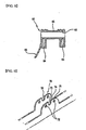
- Fig. 2 shows another coupling structure of a wiper frame 11 to a wiper arm.
- a mounting slot 12 is first formed in the wiper frame 11, and an adaptor 10 is positioned therein.
- a fastening pin 13 is then used to fasten the adaptor 10 to the frame 11.
- the structure of the wiper arm 14 for coupling to the adaptor 10 can adopt various configurations and shapes.
- the shape of the terminal coupling portion of the wiper arm 14 for coupling to the adaptor 10 can be grouped into two general categories: hooked-type and pin-type connectors.
- Fig. 3A shows a hooked-type connector at the end of a wiper arm 14 plate having a coupling slot 15 that fits over and couples with a protruding portion formed on the adaptor 10.
- Fig. 3B shows a pin-type connector having a pin 16 protruding from a side at the end of the head of the wiper arm 14, where the adaptor 10 is coupled to the pin 16.
- the coupling direction and structure of the wiper arm 14 is formed to correspond to the shape of the coupling portion at the end of the wiper arm 14.
- the wiper arm is a hooked-type arm, it inserts into the adaptor 10 from the top thereof; however, a pin-type arm inserts the pin 16 of the wiper arm 14 from the side of the wiper blade frame, as shown in Fig. 4.
- an adaptor 10 because the role of an adaptor 10 is to mount the wiper arm 14 to the frame 11, adaptors have been developed to accommodate the mounting of a variety of wiper arm 14 structures and specifications in both hooked and pin-types.
- Fig. 4 shows a wiper arm frame with two small pin holes 18 and 19 formed therein at different locations to couple with a pin 16 of a wiper arm 14 having a different diameter.
- the two smaller pin holes 18 and 19 come in only two sizes, only two sizes of wiper arm 14 pins are compatible with this type of frame 11. Also, because the central hole of the frame 11 has a fastening pin 13 inserted therein for fastening the adaptor 10 to the frame 11, this hole cannot be used. In order to couple the pin 16 of the wiper arm in the adaptor 10, the pin 16 is inserted in the pin hole 18 and 19, and the corresponding hole of the adaptor 10 must be aligned precisely for the pin 16 to pass through, so that the coupling is inconvenient.
- the adaptor 10 functions to simply support the wiper arm 14 to be able to pivot against the frame 11, and is seated and fixed to the frame 11 by only the fastening pin 13.
- the fastening pin 13 used is generally a rivet
- the riveting process permanently fixes the frame 11, so that reinforcing of the frame 11 necessitates a coupling of the adaptor 10 and a separate riveting process, increasing the number of parts and complicating the process.
- the pin 16 of the wiper arm 14 cannot be inserted into the riveted fastening pin 13, so that a small area must be used, which limits freedom of design.
- the adaptor 10 does not have a role other than fixing the wiper arm 14 to the frame 11, and is located in an area subject to much wind resistance, so that it can cause wind-induced streaking and judder.
- the present invention is directed to a vehicle wiper arm adaptor that substantially obviates one or more problems due to limitations and disadvantages of the related art.
- An object of the present invention is to provide a simplified adaptor allowing facile coupling of a wiper arm and frame without a riveting process.
- the pin on the wiper arm does not have to be manipulated for obtaining a simple coupling, and separate rivets do not have to be used, reducing the number of parts required.
- an adaptor inserted and installed on a mounting bracket of a wiper frame having a wiper blade installed thereon, the adaptor forming a pin hole for guiding and inserting a pin of a wiper arm, wherein the wiper frame forms a hole corresponding to the pin hole, the adaptor including: a pivoting portion pivotably inserted along the mounting bracket, and including an integrally formed hollow part for guiding and coupling with the pin of the wiper arm.
- a coupling structure of a wiper including: a wiper arm including a pin on an end thereof; a wiper frame including a mounting bracket that defines a guide notch; and an adaptor inserted and installed on the mounting bracket, wherein the adaptor includes: a pin hole formed therein for selectively receiving the pin; and an integrally formed pivoting portion guided and pivotably inserted in the guide notch, and having a hollow part for selectively guiding and coupling with the pin.
- Fig. 1 is a perspective view of a wiper arm coupling structure according to the related art
- Fig. 2 is a perspective view of another wiper arm coupling structure according to the related art
- Fig. 3A is a perspective view of a hooked-type wiper arm according to the related art
- Fig. 3B is a perspective view of a pin-type wiper arm according to the related art
- Fig. 4 is a perspective view showing a pin coupling structure according to the related art
- Fig. 5 is a perspective view showing a pin coupling structure according to an embodiment of the present invention.
- Fig. 6 is a plan view of a wiper arm adaptor according to an embodiment of the present invention.
- Fig. 7 is a frontal view of a wiper arm adaptor according to an embodiment of the present invention.
- Fig. 8 is a sectional view of a wiper arm adaptor according to an embodiment of the present invention.
- Fig. 9 is a perspective view showing a wiper frame structure for coupling with an adaptor according to an embodiment of the present invention.
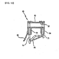
- Fig. 10 is a sectional view showing a coupled wiper adaptor according to an embodiment of the present invention.
- Fig. 5 is a perspective view showing a pin coupling structure according to an embodiment of the present invention.
- Fig. 6 is a plan view of a wiper arm adaptor according to an embodiment of the present invention.
- Fig. 7 is a frontal view of a wiper arm adaptor according to an embodiment of the present invention.
- Fig. 8 is a sectional view of a wiper arm adaptor according to an embodiment of the present invention.
- Fig. 9 is a perspective view showing a wiper frame structure for coupling with an adaptor according to an embodiment of the present invention.
- Fig. 10 is a sectional view showing a coupled wiper adaptor according to an embodiment of the present invention.
- a wiper arm adaptor 60 according to embodiments of the present invention is shown in Figs. 5 through 10.
- an adaptor 60 for a wiper arm according to the present invention is pivotably inserted and installed on a mounting bracket 71 of a wiper frame 70 having a wiper blade 80.
- the adaptor 60 forms a pin hole 61 in which a pin 91 of a wiper arm 90 inserts, and the wiper frame 70 forms a hole 72 corresponding to the pin hole 61, so that the wiper arm adaptor 60 may be installed on the wiper frame 70.
- a pivoting portion 63 is integrally formed and has a hollow part 62 to receive and couple with the pin 91 of the wiper arm 90.
- a rib 64 extends downward on the adaptor 60 to mount over the mounting bracket 71 of the wiper frame 70.
- the adaptor 60 may also include an air spoiler 65 formed thereon for directing oncoming air in an upward direction.
- the adaptor 60 in order to pivotably insert and mount the adaptor 60 on the mounting bracket 71 of the wiper frame 70 having the wiper blade 80 mounted thereon, the adaptor 60 forms the pin hole 61 for inserting the pin 91 of the wiper arm 90, and the wiper frame 70 forms a hole 72 corresponding to the pin hole 61, in order to install the adaptor 60 on the wiper arm 90.
- the adaptor 60 has a pivoting portion 63 that is integrally formed and includes a hollow part 62 to receive and couple with the pin 91 of the wiper arm 90 when the adaptor 60 is fitted onto the mounting bracket 71 of the wiper frame 70, in order to allow a pivotable mounting thereof.
- the wiper frame 70 on which the adaptor 60 is mounted, has a guide notch 73 for guiding and coupling the pivoting portion 63 of the adaptor 60.
- the guide notch 73 formed on the wiper frame 70, for guiding the pivoting portion 63 of the adaptor 60 may be formed symmetrically in both directions to balance the overall pivoting of the adaptor 60 and prevent gaps.
- the guide notch 73 formed on the wiper frame 70 may be formed on the end portion of the mounting bracket 71 of the wiper frame 70, and a sloping surface 74 may be formed at the edge of the guide notch 73 in order to facilitate the insertion of the pivoting portion 63 of the adaptor 60.
- the wiper arm adaptor 60 as shown in Figs. 5 through 10, has a coupling slot 66 formed vertically and symmetrically on both sides thereof for sliding over both portions of the mounting bracket 71 when seating the adaptor 60 over the mounting bracket 71 of the wiper frame 70.
- the wiper frame 70 includes the mounting bracket 71 for mounting the adaptor 60, so that when the adaptor 60 is pressed into the mounting bracket 71 to be assembled with the wiper frame 70, the pin hole 61 and hole 72 are mutually aligned for guiding the coupling of the pin 91 of the wiper arm 90.
- the pivoting portion 63 has a hollow part 62 for guiding the pin 91 of the wiper arm 90 - that is, the hollow part 62 is formed in the pivoting portion 63 that is installed in the mounting bracket 71 of the wiper frame 70.
- the pivoting part 63 is formed integrally on the main body of the adaptor and is coupled to the wiper frame 70 without the use of other rivets or fasteners.
- the hollow part 62 formed in the pivoting portion 63 may be used as an alternate hole to the pin hole 61 for receiving the pin 91 of the wiper arm 90.
- the rib 64 is formed downwards on the adaptor 60 to be inserted over the mounting bracket 71 of the wiper frame 70.
- the air spoiler 65 may be disposed on the adaptor to direct oncoming air upward, in order to reduce air resistance when driving.
- the adaptor 60 according to the present invention can be coupled to the wiper frame 70 without separate rivets or fasteners, to alleviate many problems associated with a wiper structure according to the related art that uses a pre-riveted frame, which is then coupled at its center to an adaptor.
- the pivoting portion 63 of the adaptor 60 is inserted along the mounting bracket 71 of the wiper frame 70.
- the integrally formed pivoting portion 63 of the adaptor 60 has a hollow part 62 that guides and couples the pin 91 of the wiper arm 90.
- the pivoting portion 63 having the hollow part 62, pivotably mounts to the mounting bracket 71 of the wiper frame 70.
- a guide notch 73 is provided at the edge portion of the mounting bracket 71 of the wiper frame 70. In this way, the adaptor 60 can be easily and firmly coupled to the wiper arm without movement of the frame 70 or gaps created.
- the guide notch 73 for guiding the pivoting portion 63 of the adaptor 60 at the edge portion of the mounting bracket 71 of the wiper frame 70, is formed symmetrically on both sides, so that when the pivoting portion 63 of the adaptor 60 is coupled thereto and pivots, an unbalanced pivoting or the formation of gaps can be prevented.
- the present invention uses the pivoting portion 63 of the adaptor 60 to fix the adaptor 60 to the frame 70, without using rivets.
- the pivoting portion 63 forms the hollow part 62 within with the adjacent pin hole 61 in order to allow a variety of pins 91 of wiper arms 90 to be easily fixed to the frame without further manipulation. That is, the aligned pin holes 61 (including the hollow part 62) allow a wide assortment of pins 91 of wiper arms 90 to be fastened thereto.
- the wiper arm adaptor and its coupling structure according to the present invention allows a simple coupling without manipulating the wiper arm pin, while eliminating the need for a rivet (that was coupled to the frame for reinforcing the frame and coupling the frame to the wiper arm in the related art).
- a rivet that was coupled to the frame for reinforcing the frame and coupling the frame to the wiper arm in the related art.
- an assortment of wiper arms may be coupled to the frame.
- judder or other problems due to movement of the adaptor or a gap formed can be prevented, providing a high-quality wiper.
Abstract
Description
- The present invention relates to an adaptor and coupling structure of a vehicular wiper arm, and more particularly, to a wiper arm adaptor with an altered pin coupling structure that is capable of coupling to a variety of wiper arms without using rivets, is easily coupled without manipulating the pin of a wiper arm, is coupled to pivot the adaptor centrally around a wiper frame, and increases the pivoting supporting strength of a wiper.
- A vehicular wiper, as shown in Figs. 1 and 2, couples a wiper arm (that moves a wiper blade) to a
frame 11 through anadaptor 10. - Fig. 1 shows a structure for coupling an
adaptor 10 to aframe 11 by permanently fixing a rivet 12a at the center of amounting slot 12. Here, the rivet 12a functions to fix theadaptor 10 and reinforce theframe 11. Because the rivet 12a needs a separate riveting process to couple to the frame 11 (increasing the manufacturing process), it also requires additional parts, which can interfere with adjacent parts and limit the degree freedom in wiper design. - Fig. 2 shows another coupling structure of a
wiper frame 11 to a wiper arm. Amounting slot 12 is first formed in thewiper frame 11, and anadaptor 10 is positioned therein. A fasteningpin 13 is then used to fasten theadaptor 10 to theframe 11. - The structure of the
wiper arm 14 for coupling to theadaptor 10 can adopt various configurations and shapes. The shape of the terminal coupling portion of thewiper arm 14 for coupling to theadaptor 10 can be grouped into two general categories: hooked-type and pin-type connectors. - Fig. 3A shows a hooked-type connector at the end of a
wiper arm 14 plate having acoupling slot 15 that fits over and couples with a protruding portion formed on theadaptor 10. - Fig. 3B shows a pin-type connector having a
pin 16 protruding from a side at the end of the head of thewiper arm 14, where theadaptor 10 is coupled to thepin 16. - The coupling direction and structure of the
wiper arm 14 is formed to correspond to the shape of the coupling portion at the end of thewiper arm 14. - That is, if the wiper arm is a hooked-type arm, it inserts into the
adaptor 10 from the top thereof; however, a pin-type arm inserts thepin 16 of thewiper arm 14 from the side of the wiper blade frame, as shown in Fig. 4. - Thus, because the role of an
adaptor 10 is to mount thewiper arm 14 to theframe 11, adaptors have been developed to accommodate the mounting of a variety ofwiper arm 14 structures and specifications in both hooked and pin-types. - Fig. 4 shows a wiper arm frame with two
small pin holes 18 and 19 formed therein at different locations to couple with apin 16 of awiper arm 14 having a different diameter. - However, because the two
smaller pin holes 18 and 19 come in only two sizes, only two sizes ofwiper arm 14 pins are compatible with this type offrame 11. Also, because the central hole of theframe 11 has a fasteningpin 13 inserted therein for fastening theadaptor 10 to theframe 11, this hole cannot be used. In order to couple thepin 16 of the wiper arm in theadaptor 10, thepin 16 is inserted in thepin hole 18 and 19, and the corresponding hole of theadaptor 10 must be aligned precisely for thepin 16 to pass through, so that the coupling is inconvenient. Theadaptor 10 functions to simply support thewiper arm 14 to be able to pivot against theframe 11, and is seated and fixed to theframe 11 by only the fasteningpin 13. Therefore, it is difficult to maintain a firm coupling, and the supporting strength weakens over time. Because the fasteningpin 13 used is generally a rivet, the riveting process permanently fixes theframe 11, so that reinforcing of theframe 11 necessitates a coupling of theadaptor 10 and a separate riveting process, increasing the number of parts and complicating the process. Thepin 16 of thewiper arm 14 cannot be inserted into the riveted fasteningpin 13, so that a small area must be used, which limits freedom of design. - Furthermore, the
adaptor 10 does not have a role other than fixing thewiper arm 14 to theframe 11, and is located in an area subject to much wind resistance, so that it can cause wind-induced streaking and judder. - Accordingly, the present invention is directed to a vehicle wiper arm adaptor that substantially obviates one or more problems due to limitations and disadvantages of the related art.
- An object of the present invention is to provide a simplified adaptor allowing facile coupling of a wiper arm and frame without a riveting process. By altering the shape and structure of the adaptor and frame, the pin on the wiper arm does not have to be manipulated for obtaining a simple coupling, and separate rivets do not have to be used, reducing the number of parts required.
- Additional advantages, objects, and features of the invention will be set forth in part in the description which follows and in part will become apparent to those having ordinary skill in the art upon examination of the following or may be learned from practice of the invention. The objectives and other advantages of the invention may be realized and attained by the structure particularly pointed out in the written description and claims hereof as well as the appended drawings.
- To achieve these objects and other advantages and in accordance with the purpose of the invention, as embodied and broadly described herein, there is provided an adaptor inserted and installed on a mounting bracket of a wiper frame having a wiper blade installed thereon, the adaptor forming a pin hole for guiding and inserting a pin of a wiper arm, wherein the wiper frame forms a hole corresponding to the pin hole, the adaptor including: a pivoting portion pivotably inserted along the mounting bracket, and including an integrally formed hollow part for guiding and coupling with the pin of the wiper arm.
- In another aspect of the present invention, there is provided a coupling structure of a wiper including: a wiper arm including a pin on an end thereof; a wiper frame including a mounting bracket that defines a guide notch; and an adaptor inserted and installed on the mounting bracket, wherein the adaptor includes: a pin hole formed therein for selectively receiving the pin; and an integrally formed pivoting portion guided and pivotably inserted in the guide notch, and having a hollow part for selectively guiding and coupling with the pin.
- It is to be understood that both the foregoing general description and the following detailed description of the present invention are exemplary and explanatory and are intended to provide further explanation of the invention as claimed.
- The accompanying drawings, which are included to provide a further understanding of the invention and are incorporated in and constitute a part of this application, illustrate embodiment(s) of the invention and together with the description serve to explain the principle of the invention. In the drawings:
- Fig. 1 is a perspective view of a wiper arm coupling structure according to the related art;
- Fig. 2 is a perspective view of another wiper arm coupling structure according to the related art;
- Fig. 3A is a perspective view of a hooked-type wiper arm according to the related art;
- Fig. 3B is a perspective view of a pin-type wiper arm according to the related art;
- Fig. 4 is a perspective view showing a pin coupling structure according to the related art;
- Fig. 5 is a perspective view showing a pin coupling structure according to an embodiment of the present invention;
- Fig. 6 is a plan view of a wiper arm adaptor according to an embodiment of the present invention;
- Fig. 7 is a frontal view of a wiper arm adaptor according to an embodiment of the present invention;
- Fig. 8 is a sectional view of a wiper arm adaptor according to an embodiment of the present invention;
- Fig. 9 is a perspective view showing a wiper frame structure for coupling with an adaptor according to an embodiment of the present invention; and
- Fig. 10 is a sectional view showing a coupled wiper adaptor according to an embodiment of the present invention.
- Reference will now be made in detail to the preferred embodiments of the present invention, examples of which are illustrated in Figs. 5 through 10. Wherever possible, the same reference numbers will be used throughout the drawings to refer to the same or like parts.
- Fig. 5 is a perspective view showing a pin coupling structure according to an embodiment of the present invention.
- Fig. 6 is a plan view of a wiper arm adaptor according to an embodiment of the present invention. Fig. 7 is a frontal view of a wiper arm adaptor according to an embodiment of the present invention. Fig. 8 is a sectional view of a wiper arm adaptor according to an embodiment of the present invention.
- Fig. 9 is a perspective view showing a wiper frame structure for coupling with an adaptor according to an embodiment of the present invention. Fig. 10 is a sectional view showing a coupled wiper adaptor according to an embodiment of the present invention.
- A
wiper arm adaptor 60 according to embodiments of the present invention is shown in Figs. 5 through 10. - Referring to Figs. 5 through 10, an
adaptor 60 for a wiper arm according to the present invention is pivotably inserted and installed on amounting bracket 71 of awiper frame 70 having awiper blade 80. - The
adaptor 60 forms apin hole 61 in which apin 91 of awiper arm 90 inserts, and thewiper frame 70 forms ahole 72 corresponding to thepin hole 61, so that thewiper arm adaptor 60 may be installed on thewiper frame 70. - In further detail, when the
adaptor 60 is fitted onto the mountingbracket 71 of thewiper frame 70, in order to allow a pivotable mounting thereof, a pivotingportion 63 is integrally formed and has ahollow part 62 to receive and couple with thepin 91 of thewiper arm 90. - A
rib 64 extends downward on theadaptor 60 to mount over the mountingbracket 71 of thewiper frame 70. - The
adaptor 60 may also include anair spoiler 65 formed thereon for directing oncoming air in an upward direction. - In the coupling structure of the wiper adaptor according to the present invention (as shown in Figs. 5, 9, and 10), in order to pivotably insert and mount the
adaptor 60 on the mountingbracket 71 of thewiper frame 70 having thewiper blade 80 mounted thereon, theadaptor 60 forms thepin hole 61 for inserting thepin 91 of thewiper arm 90, and thewiper frame 70 forms ahole 72 corresponding to thepin hole 61, in order to install theadaptor 60 on thewiper arm 90. - More specifically, the
adaptor 60 has a pivotingportion 63 that is integrally formed and includes ahollow part 62 to receive and couple with thepin 91 of thewiper arm 90 when theadaptor 60 is fitted onto the mountingbracket 71 of thewiper frame 70, in order to allow a pivotable mounting thereof. - The
wiper frame 70, on which theadaptor 60 is mounted, has aguide notch 73 for guiding and coupling the pivotingportion 63 of theadaptor 60. - Also, the
guide notch 73 formed on thewiper frame 70, for guiding the pivotingportion 63 of theadaptor 60, may be formed symmetrically in both directions to balance the overall pivoting of theadaptor 60 and prevent gaps. - The
guide notch 73 formed on thewiper frame 70 may be formed on the end portion of the mountingbracket 71 of thewiper frame 70, and asloping surface 74 may be formed at the edge of theguide notch 73 in order to facilitate the insertion of the pivotingportion 63 of theadaptor 60. - The effects of the wiper arm adaptor and its coupling structure according to the present invention are as follows.
- The
wiper arm adaptor 60 according to the present invention, as shown in Figs. 5 through 10, has acoupling slot 66 formed vertically and symmetrically on both sides thereof for sliding over both portions of the mountingbracket 71 when seating theadaptor 60 over the mountingbracket 71 of thewiper frame 70. - The
wiper frame 70 includes the mountingbracket 71 for mounting theadaptor 60, so that when theadaptor 60 is pressed into the mountingbracket 71 to be assembled with thewiper frame 70, thepin hole 61 andhole 72 are mutually aligned for guiding the coupling of thepin 91 of thewiper arm 90. - When the
adaptor 60 is inserted over the mountingbracket 71 of thewiper frame 70, it is pivotably coupled through the pivotingportion 63. The pivotingportion 63 has ahollow part 62 for guiding thepin 91 of the wiper arm 90 - that is, thehollow part 62 is formed in the pivotingportion 63 that is installed in the mountingbracket 71 of thewiper frame 70. The pivotingpart 63 is formed integrally on the main body of the adaptor and is coupled to thewiper frame 70 without the use of other rivets or fasteners. Thehollow part 62 formed in the pivotingportion 63 may be used as an alternate hole to thepin hole 61 for receiving thepin 91 of thewiper arm 90. - The
rib 64 is formed downwards on theadaptor 60 to be inserted over the mountingbracket 71 of thewiper frame 70. - Also, the
air spoiler 65 may be disposed on the adaptor to direct oncoming air upward, in order to reduce air resistance when driving. - Thus, the
adaptor 60 according to the present invention can be coupled to thewiper frame 70 without separate rivets or fasteners, to alleviate many problems associated with a wiper structure according to the related art that uses a pre-riveted frame, which is then coupled at its center to an adaptor. - As shown in Figs. 5, 9, and 10, in the wiper arm adaptor according to the present invention, the pivoting
portion 63 of theadaptor 60 is inserted along the mountingbracket 71 of thewiper frame 70. - The integrally formed pivoting
portion 63 of theadaptor 60 has ahollow part 62 that guides and couples thepin 91 of thewiper arm 90. The pivotingportion 63, having thehollow part 62, pivotably mounts to the mountingbracket 71 of thewiper frame 70. - To guide and couple the pivoting
portion 63 of theadaptor 60, aguide notch 73 is provided at the edge portion of the mountingbracket 71 of thewiper frame 70. In this way, theadaptor 60 can be easily and firmly coupled to the wiper arm without movement of theframe 70 or gaps created. - The
guide notch 73, for guiding the pivotingportion 63 of theadaptor 60 at the edge portion of the mountingbracket 71 of thewiper frame 70, is formed symmetrically on both sides, so that when the pivotingportion 63 of theadaptor 60 is coupled thereto and pivots, an unbalanced pivoting or the formation of gaps can be prevented. Theguide notch 73 formed, in the mountingbracket 71 of thewiper frame 70, forms the slopedsurface 74 to facilitate guiding and coupling of the pivotingportion 63 of theadaptor 60. - The present invention uses the pivoting
portion 63 of theadaptor 60 to fix theadaptor 60 to theframe 70, without using rivets. At the same time, the pivotingportion 63 forms thehollow part 62 within with theadjacent pin hole 61 in order to allow a variety ofpins 91 ofwiper arms 90 to be easily fixed to the frame without further manipulation. That is, the aligned pin holes 61 (including the hollow part 62) allow a wide assortment ofpins 91 ofwiper arms 90 to be fastened thereto. - The wiper arm adaptor and its coupling structure according to the present invention allows a simple coupling without manipulating the wiper arm pin, while eliminating the need for a rivet (that was coupled to the frame for reinforcing the frame and coupling the frame to the wiper arm in the related art). By not using a rivet, the number of parts, the number of manufacturing processes, and resultantly, the cost of the simplified manufacturing of the wiper are reduced. Also, an assortment of wiper arms may be coupled to the frame. Additionally, when the adaptor is coupled to the frame using the pivoting portion, judder or other problems due to movement of the adaptor or a gap formed can be prevented, providing a high-quality wiper.
- It will be apparent to those skilled in the art that various modifications and variations can be made in the present invention. Thus, it is intended that the present invention covers the modifications and variations of this invention provided they come within the scope of the appended claims and their equivalents.
Claims (6)
- An adaptor inserted and installed on a mounting bracket of a wiper frame having a wiper blade installed thereon, the adaptor forming a pin hole for guiding and inserting a pin of a wiper arm, wherein the wiper frame forms a hole corresponding to the pin hole, the adaptor comprising:a pivoting portion pivotably inserted along the mounting bracket, and including an integrally formed hollow part for guiding and coupling with the pin of the wiper arm.
- The adaptor according to claim 1, further comprising a rib mounted along the mounting bracket.
- The adaptor according to claim 1, further comprising an air spoiler for directing oncoming air in an upward direction.
- A coupling structure of a wiper comprising:a wiper arm including a pin on an end thereof;a wiper frame including a mounting bracket that defines a guide notch; andan adaptor inserted and installed on the mounting bracket,wherein the adaptor includes:a pin hole formed therein for selectively receiving the pin; andan integrally formed pivoting portion guided and pivotably inserted in the guide notch, and having a hollow part for selectively guiding and coupling with the pin.
- The coupling structure according to claim 4, wherein the guide notch is formed symmetrically in duplicate.
- The coupling structure according to claim 4, wherein the guide notch has an open end with a sloped surface for guiding the inserting of the pivoting portion.
Applications Claiming Priority (1)
| Application Number | Priority Date | Filing Date | Title |
|---|---|---|---|
| KR1020060016099A KR100666088B1 (en) | 2006-02-20 | 2006-02-20 | Wiper arm adaptor for car |
Publications (2)
| Publication Number | Publication Date |
|---|---|
| EP1820705A2 true EP1820705A2 (en) | 2007-08-22 |
| EP1820705A3 EP1820705A3 (en) | 2010-01-27 |
Family
ID=37867272
Family Applications (1)
| Application Number | Title | Priority Date | Filing Date |
|---|---|---|---|
| EP06019753A Withdrawn EP1820705A3 (en) | 2006-02-20 | 2006-09-21 | Wiper arm adaptor for car |
Country Status (4)
| Country | Link |
|---|---|
| US (1) | US7506401B2 (en) |
| EP (1) | EP1820705A3 (en) |
| KR (1) | KR100666088B1 (en) |
| CA (1) | CA2569011A1 (en) |
Cited By (2)
| Publication number | Priority date | Publication date | Assignee | Title |
|---|---|---|---|---|
| US7395577B2 (en) * | 2006-07-19 | 2008-07-08 | Fu Gang Co., Ltd. | Universal connection device for windshield wiper blade |
| EP2471693A4 (en) * | 2009-08-26 | 2017-11-08 | Cap Corporation | Multi-adapter for a vehicle wiper |
Families Citing this family (27)
| Publication number | Priority date | Publication date | Assignee | Title |
|---|---|---|---|---|
| US7921503B1 (en) * | 2009-10-30 | 2011-04-12 | Fu Gang Co., Ltd. | Structure of windshield wiper |
| US9174609B2 (en) | 2011-04-21 | 2015-11-03 | Pylon Manufacturing Corp. | Wiper blade with cover |
| US9457768B2 (en) | 2011-04-21 | 2016-10-04 | Pylon Manufacturing Corp. | Vortex damping wiper blade |
| WO2013016493A1 (en) | 2011-07-28 | 2013-01-31 | Pylon Manufacturing Corp. | Windshield wiper adapter, connector and assembly |
| MX347284B (en) * | 2011-07-29 | 2017-04-21 | Pylon Mfg Corp | Windshield wiper connector. |
| US9108595B2 (en) | 2011-07-29 | 2015-08-18 | Pylon Manufacturing Corporation | Windshield wiper connector |
| US9180839B2 (en) * | 2011-12-29 | 2015-11-10 | Federal-Mogul Corporation | Windscreen wiper device |
| US20130219649A1 (en) | 2012-02-24 | 2013-08-29 | Pylon Manufacturing Corp. | Wiper blade |
| US10723322B2 (en) | 2012-02-24 | 2020-07-28 | Pylon Manufacturing Corp. | Wiper blade with cover |
| CA2865292C (en) | 2012-02-24 | 2018-03-13 | Pylon Manufacturing Corp. | Wiper blade |
| US10829092B2 (en) | 2012-09-24 | 2020-11-10 | Pylon Manufacturing Corp. | Wiper blade with modular mounting base |
| KR101895765B1 (en) * | 2013-02-21 | 2018-09-05 | 주식회사 캐프 | A Connector of Wiper Blade |
| US10166951B2 (en) | 2013-03-15 | 2019-01-01 | Pylon Manufacturing Corp. | Windshield wiper connector |
| US9555775B2 (en) | 2013-03-15 | 2017-01-31 | Illinois Tool Works Inc. | Connectors and connector kit for attachment of a windshield wiper blade to multiple types of windshield wiper arms |
| US9511748B2 (en) | 2013-03-15 | 2016-12-06 | Illinois Tool Works Inc. | Universal connector for attachment of a windshield wiper blade with multiple types of windshield wiper arms |
| KR101474838B1 (en) | 2013-07-01 | 2014-12-22 | 주식회사 캐프 | A Wiper Blade Assembly |
| USD727238S1 (en) | 2013-12-13 | 2015-04-21 | Illinois Tool Works Inc. | Cover used for windshield wiper connectors |
| US9505380B2 (en) | 2014-03-07 | 2016-11-29 | Pylon Manufacturing Corp. | Windshield wiper connector and assembly |
| USD787308S1 (en) | 2014-10-03 | 2017-05-23 | Pylon Manufacturing Corp. | Wiper blade package |
| USD777079S1 (en) | 2014-10-03 | 2017-01-24 | Pylon Manufacturing Corp. | Wiper blade frame |
| US10363905B2 (en) | 2015-10-26 | 2019-07-30 | Pylon Manufacturing Corp. | Wiper blade |
| FR3043042B1 (en) * | 2015-11-04 | 2017-12-15 | Valeo Systemes Dessuyage | ADAPTER FOR A WINDSCREEN WIPER OF A MOTOR VEHICLE |
| EP3458315B1 (en) | 2016-05-19 | 2021-09-08 | Pylon Manufacturing Corp. | Windshield wiper blade |
| US10661759B2 (en) | 2016-05-19 | 2020-05-26 | Pylon Manufacturing Corporation | Windshield wiper connector |
| WO2017201470A1 (en) | 2016-05-19 | 2017-11-23 | Pylon Manufacturing Corp. | Windshield wiper connector |
| US11040705B2 (en) | 2016-05-19 | 2021-06-22 | Pylon Manufacturing Corp. | Windshield wiper connector |
| US10766462B2 (en) | 2016-05-19 | 2020-09-08 | Pylon Manufacturing Corporation | Windshield wiper connector |
Citations (6)
| Publication number | Priority date | Publication date | Assignee | Title |
|---|---|---|---|---|
| GB920059A (en) * | 1961-02-03 | 1963-03-06 | Bosch Gmbh Robert | Improvements in or relating to windscreen wiper assemblies |
| GB2237502A (en) * | 1989-10-19 | 1991-05-08 | China Wiper Special Rubber Co | A windscreen wiper blade assembly |
| FR2729352A1 (en) * | 1995-01-13 | 1996-07-19 | Journee Paul Sa | Motor vehicle windscreen wiper with aerodynamic shield |
| WO2003051695A2 (en) * | 2001-12-19 | 2003-06-26 | Robert Bosch Gmbh | Windscreen wiper with a wiper arm |
| FR2846617A1 (en) * | 2002-11-04 | 2004-05-07 | Valeo Systemes Dessuyage | Adaptor for standard windscreen wiper mounting comprises body with bore and transverse groove on upper face and connection to mounting |
| DE10349637A1 (en) * | 2003-10-24 | 2005-06-02 | Robert Bosch Gmbh | Articulated joint for use between wiper arm and blade, has base cap closing window between spoiler parts and closing two parallel side walls of adaptor from outside to provide closed interconnection between cap and adaptor |
Family Cites Families (8)
| Publication number | Priority date | Publication date | Assignee | Title |
|---|---|---|---|---|
| FR1581569A (en) * | 1968-06-18 | 1969-09-19 | ||
| CH611563A5 (en) * | 1977-04-04 | 1979-06-15 | Tech Handelsberatung Establish | Motor vehicle windscreen wiper with means for retaining the pin of the wiper arm |
| FR2653080B1 (en) * | 1989-10-13 | 1991-12-06 | Journee Paul Sa | CONNECTOR DEVICE FOR WINDSCREEN WIPER BLADE, PARTICULARLY FOR MOTOR VEHICLE. |
| US5383248A (en) * | 1991-03-29 | 1995-01-24 | Ho; Chang S. Y. | Structure of double-blade wind shieldwiper with arm to blade connectors |
| DE10162399A1 (en) * | 2001-12-19 | 2003-07-10 | Bosch Gmbh Robert | Wipers with a wiper arm |
| FR2846616B1 (en) * | 2002-11-04 | 2006-02-03 | Valeo Systemes Dessuyage | WIPER BLADE BRUSH FRAME WITH A FASTENING ARRANGEMENT OF AT LEAST ONE ARM |
| US20060130263A1 (en) * | 2004-12-17 | 2006-06-22 | Coughlin Timothy J | Wiper coupler and wiper assembly incorporating same |
| KR100617017B1 (en) * | 2005-04-18 | 2006-08-30 | 케이씨더블류 주식회사 | Cap for wiper connector |
-
2006
- 2006-02-20 KR KR1020060016099A patent/KR100666088B1/en not_active IP Right Cessation
- 2006-09-21 EP EP06019753A patent/EP1820705A3/en not_active Withdrawn
- 2006-11-20 CA CA002569011A patent/CA2569011A1/en not_active Abandoned
- 2006-11-22 US US11/562,723 patent/US7506401B2/en not_active Expired - Fee Related
Patent Citations (6)
| Publication number | Priority date | Publication date | Assignee | Title |
|---|---|---|---|---|
| GB920059A (en) * | 1961-02-03 | 1963-03-06 | Bosch Gmbh Robert | Improvements in or relating to windscreen wiper assemblies |
| GB2237502A (en) * | 1989-10-19 | 1991-05-08 | China Wiper Special Rubber Co | A windscreen wiper blade assembly |
| FR2729352A1 (en) * | 1995-01-13 | 1996-07-19 | Journee Paul Sa | Motor vehicle windscreen wiper with aerodynamic shield |
| WO2003051695A2 (en) * | 2001-12-19 | 2003-06-26 | Robert Bosch Gmbh | Windscreen wiper with a wiper arm |
| FR2846617A1 (en) * | 2002-11-04 | 2004-05-07 | Valeo Systemes Dessuyage | Adaptor for standard windscreen wiper mounting comprises body with bore and transverse groove on upper face and connection to mounting |
| DE10349637A1 (en) * | 2003-10-24 | 2005-06-02 | Robert Bosch Gmbh | Articulated joint for use between wiper arm and blade, has base cap closing window between spoiler parts and closing two parallel side walls of adaptor from outside to provide closed interconnection between cap and adaptor |
Cited By (2)
| Publication number | Priority date | Publication date | Assignee | Title |
|---|---|---|---|---|
| US7395577B2 (en) * | 2006-07-19 | 2008-07-08 | Fu Gang Co., Ltd. | Universal connection device for windshield wiper blade |
| EP2471693A4 (en) * | 2009-08-26 | 2017-11-08 | Cap Corporation | Multi-adapter for a vehicle wiper |
Also Published As
| Publication number | Publication date |
|---|---|
| KR100666088B1 (en) | 2007-01-10 |
| US20070192984A1 (en) | 2007-08-23 |
| CA2569011A1 (en) | 2007-08-20 |
| US7506401B2 (en) | 2009-03-24 |
| EP1820705A3 (en) | 2010-01-27 |
Similar Documents
| Publication | Publication Date | Title |
|---|---|---|
| US7506401B2 (en) | Wiper arm adaptor for car | |
| KR101245514B1 (en) | Wiper blade | |
| US8479351B2 (en) | Windshield wiper assembly | |
| JP5941101B2 (en) | Adapter and connection base for automotive wiper blade connectors | |
| CN102149581B (en) | Device for articulated connection of wiper blade to wiper arm of windshield wiper | |
| CA2617013C (en) | Wiper blade | |
| CN101311043B (en) | Wiper blade | |
| US20150251635A1 (en) | Wiper blade | |
| JP2002534311A (en) | Automotive wiper with means for connecting wiper blades | |
| PL211790B1 (en) | Joint member for wiper blade and wiper blade | |
| US9862356B2 (en) | Wiper blade | |
| US20020192017A1 (en) | Wiper blade coupler with shim | |
| US20150321646A1 (en) | Adapter for windshield wiper assembly | |
| JP2007055589A (en) | Wiper device | |
| JP4227156B2 (en) | Wiper blade | |
| JP4203069B2 (en) | Wiper blade | |
| CN218258389U (en) | Instrument panel | |
| KR20210047270A (en) | Hybrid Windshield Wiper Blade | |
| CN211765423U (en) | Dual-purpose windshield wiper convenient for dismounting decorative strip | |
| CN218258027U (en) | Wire harness fixing device and vehicle | |
| CN212389616U (en) | Connecting piece for connecting ceiling lining and skylight frame, roof structure and vehicle | |
| JP7406954B2 (en) | Installation device for vehicle interior parts | |
| KR101006845B1 (en) | Outside handle having pinless lever assembly structure for vehicle | |
| JPH09142261A (en) | Wiper blade | |
| JP4227083B2 (en) | Wiper blade |
Legal Events
| Date | Code | Title | Description |
|---|---|---|---|
| PUAI | Public reference made under article 153(3) epc to a published international application that has entered the european phase |
Free format text: ORIGINAL CODE: 0009012 |
|
| AK | Designated contracting states |
Kind code of ref document: A2 Designated state(s): AT BE BG CH CY CZ DE DK EE ES FI FR GB GR HU IE IS IT LI LT LU LV MC NL PL PT RO SE SI SK TR |
|
| AX | Request for extension of the european patent |
Extension state: AL BA HR MK YU |
|
| PUAL | Search report despatched |
Free format text: ORIGINAL CODE: 0009013 |
|
| AK | Designated contracting states |
Kind code of ref document: A3 Designated state(s): AT BE BG CH CY CZ DE DK EE ES FI FR GB GR HU IE IS IT LI LT LU LV MC NL PL PT RO SE SI SK TR |
|
| AX | Request for extension of the european patent |
Extension state: AL BA HR MK RS |
|
| STAA | Information on the status of an ep patent application or granted ep patent |
Free format text: STATUS: THE APPLICATION IS DEEMED TO BE WITHDRAWN |
|
| AKY | No designation fees paid | ||
| 18D | Application deemed to be withdrawn |
Effective date: 20100401 |
|
| REG | Reference to a national code |
Ref country code: DE Ref legal event code: 8566 |