EP1820535A1 - Atrialer Defibrillator - Google Patents
Atrialer Defibrillator Download PDFInfo
- Publication number
- EP1820535A1 EP1820535A1 EP07000831A EP07000831A EP1820535A1 EP 1820535 A1 EP1820535 A1 EP 1820535A1 EP 07000831 A EP07000831 A EP 07000831A EP 07000831 A EP07000831 A EP 07000831A EP 1820535 A1 EP1820535 A1 EP 1820535A1
- Authority
- EP
- European Patent Office
- Prior art keywords
- atrial
- wave
- ventricular
- amplitude
- sensed
- Prior art date
- Legal status (The legal status is an assumption and is not a legal conclusion. Google has not performed a legal analysis and makes no representation as to the accuracy of the status listed.)
- Granted
Links
Images


Classifications
-
- A—HUMAN NECESSITIES
- A61—MEDICAL OR VETERINARY SCIENCE; HYGIENE
- A61N—ELECTROTHERAPY; MAGNETOTHERAPY; RADIATION THERAPY; ULTRASOUND THERAPY
- A61N1/00—Electrotherapy; Circuits therefor
- A61N1/02—Details
- A61N1/04—Electrodes
- A61N1/05—Electrodes for implantation or insertion into the body, e.g. heart electrode
- A61N1/056—Transvascular endocardial electrode systems
- A61N1/0563—Transvascular endocardial electrode systems specially adapted for defibrillation or cardioversion
-
- A—HUMAN NECESSITIES
- A61—MEDICAL OR VETERINARY SCIENCE; HYGIENE
- A61N—ELECTROTHERAPY; MAGNETOTHERAPY; RADIATION THERAPY; ULTRASOUND THERAPY
- A61N1/00—Electrotherapy; Circuits therefor
- A61N1/18—Applying electric currents by contact electrodes
- A61N1/32—Applying electric currents by contact electrodes alternating or intermittent currents
- A61N1/38—Applying electric currents by contact electrodes alternating or intermittent currents for producing shock effects
- A61N1/39—Heart defibrillators
- A61N1/3956—Implantable devices for applying electric shocks to the heart, e.g. for cardioversion
- A61N1/3962—Implantable devices for applying electric shocks to the heart, e.g. for cardioversion in combination with another heart therapy
- A61N1/39622—Pacing therapy
-
- A—HUMAN NECESSITIES
- A61—MEDICAL OR VETERINARY SCIENCE; HYGIENE
- A61N—ELECTROTHERAPY; MAGNETOTHERAPY; RADIATION THERAPY; ULTRASOUND THERAPY
- A61N1/00—Electrotherapy; Circuits therefor
- A61N1/18—Applying electric currents by contact electrodes
- A61N1/32—Applying electric currents by contact electrodes alternating or intermittent currents
- A61N1/38—Applying electric currents by contact electrodes alternating or intermittent currents for producing shock effects
- A61N1/39—Heart defibrillators
- A61N1/3987—Heart defibrillators characterised by the timing or triggering of the shock
-
- A—HUMAN NECESSITIES
- A61—MEDICAL OR VETERINARY SCIENCE; HYGIENE
- A61N—ELECTROTHERAPY; MAGNETOTHERAPY; RADIATION THERAPY; ULTRASOUND THERAPY
- A61N1/00—Electrotherapy; Circuits therefor
- A61N1/18—Applying electric currents by contact electrodes
- A61N1/32—Applying electric currents by contact electrodes alternating or intermittent currents
- A61N1/38—Applying electric currents by contact electrodes alternating or intermittent currents for producing shock effects
- A61N1/39—Heart defibrillators
- A61N1/395—Heart defibrillators for treating atrial fibrillation
Definitions
- the present invention generally relates to an atrial defibrillator for delivering an atrial defibrillation shock to an atrium of a heart suffering from atrial fibrillation (AF).
- the atrial defibrillator preferably is an implantable cardioverter/defibrillator (ICD) that also provides for basic or sophisticated pacing functionality of a dual or more chamber implantable pacemaker.
- ICD implantable cardioverter/defibrillator
- the invention relates to an atrial defibrillator capable of delivering an atrial defibrillation shock synchronous to a ventricular contraction.
- the atrial defibrillator comprises at least one stimulation pulse generator to generate pacing pulses for at least a ventricle of a heart. Further, the atrial defibrillator comprises at least one sensing stage for sensing of intrinsic ventricular events, said intrinsic ventricular event being an R-wave having an amplitude with a measured magnitude.
- the atrial defibrillator further comprises an atrial shock generator to generate an atrial defibrillation shock and an atrial fibrillation detector adapted to detect an atrial fibrillation.
- a control unit connected to the stimulation pulse generator, the sensing stage, the atrial fibrillation detector and the fibrillation shock generator is adapted to trigger an atrial defibrillation shock after detection of an atrial fibrillation synchronous with a sensed or paced ventricular event.
- Fibrillation is a particular form of tachycardia that may occur as well in an atrium (atrial fibrillation) as in a ventricle (ventricular fibrillation) of a heart.
- Other forms of tachycardia are, for example, flutter.
- a tachycardia is characterized by a rapid heart rate.
- fibrillation is characterized by a very high rate of contraction of the heart chamber (atrium or ventricle) affected and of very low amplitude of the sensed electrical potential.
- VF ventricular fibrillation
- atrial fibrillation usually is lethal if not treated within minutes or seconds.
- atrial fibrillation usually is not life threatening, since the atrial contraction only contributes to a smaller part to the total pumping power of the heart that is typically expressed as an minute volume: pumped blood volume per minute.
- a typical treatment o£ a fibrillation is the delivery of a defibrillation shock to the fibrillating heart chamber.
- a defibrillation shock usually has a much higher intensity than for example a stimulation or pacing pulse.
- the intensity of a defibrillation shock shall be sufficient to render the whole myocardium of the fibrillating heart chamber refractory in order to interrupt a circulating excitation of the myocardium and thus to synchronize the contraction of the myocardium of the heart chamber in all it's parts.
- Atrial fibrillation or atrial flutter is not life threatening, there are several reasons for treating atrial fibrillation, although such treatment is painful for the patient. One reason is that the atrial fibrillation my lead to lethal ventricular fibrillation. Also, atrial fibrillation is compromising the heart's performance because of the loss of atrioventricular synchrony associate with an atrial fibrillation and can cause discomfort as for example, fatigue.
- An atrial defibrillation shock for treatment of an atria] fibrillation usually is applied by means of intraatrial shock electrodes.
- an atrial defibrillation shock is delivered at the wrong point of time during a heart cycle, the atrial defibrillation itself can cause a ventricular fibrillation.
- ventricular event may be the sensed event in case of a natural (intrinsic) contraction of the ventricle or a paced event, if the contraction of the ventricle is caused by a ventricular stimulation pulse.
- US Pat. No. 5,282,836 for example, the disclosure of which is hereby incorporated by reference herein, discloses an atrial defibrillator capable of providing pre-cardioversion pacing.
- pre-cardioversion pacing the ventricle is stimulated with a fixed pacing rate for a determined number of cardiac cycles in order to establish a stable ventricular rhythm to which the atria] defibrillation shock can be synchronized with.
- an atrial defibrillator having a control unit that is adapted to compare a sensed R-wave amplitude with a reference R-wave amplitude and synchronize an atrial defibrillation shock with either a paced ventricular event or a sensed ventricular event if said sensed ventricular event is an R-wave having an amplitude of at least 60 % of the magnitude of said reference amplitude.
- the invention is based on the insight that in some cases, the sensed signal characterizing a ventricular repotarisation - a T-wave - is misinterpreted as R-wave. If an atrial defibrillation shock is synchronized with a T-wave instead of an R-wave, there is a serious risk of inducing a ventricular fibrillation since the T-wave occurs during the vulnerable phase of the myocardium. In order to avoid such misinterpretation of a T-wave as an R-wave, a criterion for discriminating T-waves from R-waves is introduced, the criterion being an amplitude criterion.
- a pacemaker In order to monitor the heart chamber and thus to determine whether or not a natural contraction of a heart chamber has occurred, a pacemaker has a sensing stage which during operation of the pacemaker is connected to an electrode placed in a respective heart chamber. A natural contraction of a heart chamber can be detected by evaluating electrical potentials sensed by such sensing electrode. In the sensed electrical signal, the depolarization of an atrium muscle tissue is manifested by occurrence of a signal known as "P-wave". Similarly, the depolarization of ventricular muscle tissue is manifested by the occurrence of a signal known as "R-wave". A Pwave or an R-wave represent a sensed atrial event or a sensed ventricular event, respectively, in the further course of this application.
- An atrial sensing stage senses P-waves as sensed atrial events As, a ventricular sensing stage senses R-waves (sensed ventricular events Vs) and T-waves.
- the atrial sensing stage may be connected to an atrial fibrillation detector which is adapted to detect an atria( fibrillation by evaluating the atrial sense signal generated by the atrial sensing stage. Criteria for detection of atrial fibrillation are a high atrial rate (high frequency of atria] sensed events) and a low amplitude of sensed P-waves. Criteria for detection of atrial fibrillation are well known in the art.
- Sensing stages usually include bandpass-filters to pre-process the electrical signals received by an intracardiac sensing electrodes.
- the ventricular sensing stage for sensing R-waves has a bandpass-filter with a passband from 15 to 80 Hertz.
- Such bandpass-filter is suitable to reduce the T-wave amplitude as compared to the R-wave amplitude.
- the ventricular sensing stage is less susceptible to wrongly sensed T-waves as R-waves.
- the atrial defibrillation shock is delivered within 30-100 ms after detection of an R-wave having an amplitude with a magnitude of at least 60 % of the magnitude of the referent amplitude.
- a time interval of ⁇ I00 ms is considered to be short enough to avoid delivery of the atrial defibrillation shock during the vulnerable phase of the ventricle.
- the atrial defibrillator comprises a memory for storing sampled R-wave amplitudes sensed during episodes of sinus rate.
- a sinus rate is present, if no ventricular or atrial tachycardia (including flutter and fibrillation) is present.
- the control unit preferably is adapted to access the memory and to generate a mean value from R-wave amplitude values stored in said memory and to use the mean amplitude value as a reference amplitude.
- the ventricular sensing stage preferably comprises a second filter having a lower cut of frequency of 22 to 26 Hertz, i.e a bandpass-filter having a pass band between 24 and 80 Hz. This allows more specific detection of R-waves.
- the first filter having a pass band from 15 to 80 Hz and the second filter having a pass band from 24 to 80 Hz may be switched in parallel to each other so that they are permanently operational or they may be switchably connected to the control unit.
- the control unit is adapted to switch back and forth between the two filters depending on the operational state of the atrial defibrillator.
- the atrial defibrillation shock is delivered within 30-100 ms after detection of an R-wave synchronously detected by the first and second bandpass-filter and having an amplitude with a magnitude of at least 60 % of the magnitude of the referent amplitude, measured with the second bandpass-filter.
- a time interval of ⁇ 100 ms is considered to be short enough to avoid delivery of the atrial defibrillation shock during the vulnerable phase of the ventricle.
- the atrial defibrillator comprises a memory for storing sampled R-wave amplitudes sensed during episodes of sinus rate.
- a sinus rate is present, if no ventricular or atrial tachycardia (including flutter and fibrillation) is present.
- the control unit preferably is adapted to access the memory and to generate a mean value from R-wave amplitude values stored in said memory and to use the mean amplitude value as a reference amplitude.
- the ventricular signal filtered by the bandpass-filter having a pass band between 24 and 80 Hz is used for storing in said memory.
- the atrial defibrillator preferably comprises an impedance sensor connected to an impedance evaluation unit which is adapted to detect ventricular contractions by evaluating an intracardiac impedance signal. This allows for detection of mechanical contraction of the ventricle and thus a confirmation of a depolarisation of the myocardium.
- control unit is connected to the impedance evaluation unit and is adapted to evaluate an actual intracardiac impedance signal by comparing said actual intracardiac impedance signal with a stored reference intracardiac impedance signal.
- control unit is further adapted to form a difference area between an actual impedance signal and a stored reference impedance signal and to compare the difference area to a stored reference area, said stored reference area representing the area defined by the reference impedance signal.
- the control unit is preferably adapted to evaluate the intracardiac impedance signal in a time window starting with a sensed ventricular event (which should be an R-wave but also could be a T-wave wrongly sensed as R-wave) and ending after 30 to 100 ms and to suppress delivery of an atrial defibrillation shock when the difference area is larger than 10 to 20% of the reference area.
- a sensed ventricular event which should be an R-wave but also could be a T-wave wrongly sensed as R-wave
- control unit suppresses delivery of an atrial defibrillation shock when the difference area is larger than 15% of the reference area.
- a preferred implantable medical device comprises all components of an advanced dual chamber demand pacemaker. These components in particular may include atrial and ventricular sensing stages and atrial and ventricular stimulation pulse generators. Furthermore, the implantable medical device (atrial defibrillator/pacemaker) comprises an activity sensor to allow for rate adaptive pacing with a pacing rate matching the hemodynamic demand.
- intracardiac electrodes electrode suitable for placement in an heart chamber, in particular the right ventricle and the right atrium of a heart
- sensing stages sense amplifiers having a band pass filter characteristic providing some adjustable gain for amplification of sensed signals housed in an implanted pacemaker.
- Electrical activity changes of sensed electrical potentials caused by depolarization/repolarization of the myocardium
- the pacemaker assumes that a depolarization or contraction of the indicated chamber has occurred.
- a pulse generator also housed within the pacemaker housing, generates a stimulation pulse that is delivered to the indicated chamber, usually via the same lead or electrode as is used for sensing.
- Separate stimulation pulse generators are usually provided for each heart chamber (atrium or ventricle) to be stimulated.
- the control unit triggers the generation of a respective atrial or ventricular stimulation pulse according to a pre-programmed, variable timing regime in order to provide for adequate timing of the stimulation pulses.
- a stimulation pulse to the myocardium may cause a contraction of a respective heart chamber, if the myocardium of that chamber is not in a refractory state and if the stimulation pulse has an intensity above the stimulation threshold of said myocardium.
- a pacemaker Depending on the mode of operation, a pacemaker only delivers a stimulation pulse (pacing pulse) to a heart chamber (atrium or ventricle) if needed, that is, if no natural contraction of that chamber occurs.
- a stimulation pulse pacing pulse
- Such mode of operation is called an inhibited or demand mode of operation since the delivery of a stimulation pulse is inhibited if a natural contraction of the heart chamber is sensed within a predetermined time interval (usually called escape interval) so the heart chamber is only stimulated if demanded.
- the pacemaker/atrial defibrillator monitors the heart chamber to be stimulated in order to determine if a cardiac contraction (heartbeat) has naturally occurred.
- a cardiac contraction also referred to as "intrinsic” or “signs” cardiac activity
- cardiac contraction also referred to as "intrinsic” or “signs” cardiac activity
- depolarization and contraction may be considered as simultaneous events and the terns "depolarization” and “contraction” are used herein as synonyms.
- the pacemaker/atrial defibrillator monitors the heart for the occurrence of P-waves and/or R-waves. If such signals are sensed within a prescribed time period or time window, which is called atria] or ventricular escape interval, respectively, then the escape interval is reset (i.e., restarted) and generation of a stimulation pulse is inhibited and no unnecessary stimulation pulse is triggered.
- atria a prescribed time period or time window
- the escape interval is measured from the last heartbeat, i.e., from the last occurrence of an intrinsic (sensed) atrial event (P-wave, A-sense, As) if the atrium is monitored, or an intrinsic (sensed) ventricular event (R-wave, V-sense, Vs) if the ventricle is monitored, or the generation of a stimulation pulse (V-pace, Vp; A-pace, AP) if no respective intrinsic event has occurred.
- the pacemaker provides stimulation pulses "on demand,” i.e., only as needed, when intrinsic cardiac activity does not occur within the prescribed escape interval.
- the pacing modes of a pacemaker are classified by type according to a three letter code.
- the first letter identifies the chamber of the heart that is paced (i.e., that chamber where a stimulation pulse is delivered), with a "V” indicating the ventricle, an "A” indicating the atrium, and a "D” indicating both the atrium and ventricle.
- the second letter of the code identifies the chamber wherein cardiac activity is sensed, using the same letters, and wherein an "O" indicates no sensing occurs.
- the third letter of the code identifies the action or response that is taken by the pacemaker.
- an Inhibiting ("I") response wherein a stimulation pulse is delivered to the designated chamber at the conclusion of the appropriate escape interval unless cardiac activity is sensed during the escape interval, in which case the stimulation pulse is inhibited
- a Trigger ("T") response wherein a stimulation pulse to a prescribed chamber of the heart a prescribed period of time after a sensed event
- a Dual (“D") response wherein both the Inhibiting mode and Trigger mode may be evoked, e.g., with the "inhibiting" occurring in one chamber of the heart and the "triggering" in the other.
- a fourth letter “R” may be added to designate a rate-responsive pacemaker and/or whether the rate-responsive features of such a rate-responsive pacemaker are enabled ("O" typically being used to designate that rate-responsive operation has been disabled).
- a rate-responsive pacemaker is one wherein a specified parameter or combination of parameters, such as physical activity, the amount of oxygen in the blood, the temperature of the blood, etc., is sensed with an appropriate sensor and is used as a physiological indicator of what the pacing rate should be. When enabled, such rate-responsive pacemaker thus provides stimulation pulses that best meet the physiological demands of the patient.
- Multiple-mode, demand-type, cardiac pacemakers shall allow a sequence of contractions of the heart's chamber which equals as far as possible a natural behavior of the healthy heart for damaged or diseased hearts that are unable to do so on their own.
- SA node sinoatrial node
- AV node atrioventricular node
- the ventricle contracts, forcing the blood out of the ventricle to body tissue.
- a typical time interval between contraction of the atrium and contraction of the ventricle might be 60 ms; a typical time interval between contraction of the ventricle and the next contraction of the atrium might be 800 ms.
- a dual-chamber pacemaker defines a basic atrial escape interval (AEI) that sets the time interval between a ventricular event and an atrial event; as well as a basic AV delay (AVD) or ventricular escape interval (VEI) that sets the time interval or delay between an atrial event and a ventricular event.
- a "ventricular event” may refer either to a natural ventricular contraction (intrinsic ventricular event) which is sensed as an R-wave or to a ventricular stimulation pulse (V-pulse, VP).
- an atrial event shall refer to both, a P-wave or an atrial stimulation pulse (A-pulse, A P ).
- the AEI and AVID thus a length of a heart cycle which is reciprocal to the pacing rate at which stimulation pulses are generated and delivered to a patient's heart in the absence of sensed natural cardiac activity.
- these electrodes are coupled through intravenous and/or epicardial leads to sense amplifiers housed in an implanted pacemaker. Electrical activity occurring in these chambers can thus be sensed. When electrical activity is sensed, the pacemaker assumes that a depolarization or contraction of the indicated chamber has occurred.
- a pulse generator also housed within the pacemaker housing, generates a stimulation pulse that is delivered to the indicated chamber, usually via the same lead or electrode as is used for sensing.
- the atrial defibrillator is part of an implantable medical device that is adapted to also provide the pacing modes disclosed above since pacing of the ventricle may be necessary to stabilize the ventricular rhythm in order reliably synchronize the atrial defibrillation shock with a ventricular contraction.
- the implantable medical device including the atrial defibrillator may comprise means for ventricular defibrillation and/or means for left ventricular stimulation in addition to right ventricular stimulation.
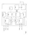
- a dual chamber pacemaker/atria) defibrillator (implantable medical device, IMD) 10 connected to pacing/sensing leads placed in a heart 12 is illustrated.
- the IMD 10 is coupled to a heart 12 by way of leads 14 and 16, the lead 14 having a pair of right atrial electrodes 18 and 20 that are in contact with the right atrium 28 of the heart 12, and the lead 16 having a pair of electrodes 22 and 24 that are in contact with the right ventricle 30 of heart 12.
- Lead 16 furthermore carries an atrial shock electrode 26 placed in the right atrium.
- Electrodes 18 and 22 are tip-electrodes at the very distal end of leads 14 and 15, respectively.
- Electrode 18 is a right atrial tip electrode RA-Tip and electrode 22 is a right ventricular tip electrode 22.
- Electrodes 20 and 24 are designed as ring electrode in close proximity but electrically isolated from the respective tip electrodes 18 and 22.
- Electrode 20 forms a right atrial tip electrode RA-Ring and electrode 24 forms a right ventricular ring electrode RV-Ring.
- Atrial shock electrode 26 is a coil electrode having a large surface compared to Tip- and Ring-electrodes 18 to 24.
- leads 14 and 16 are connected to respective output/input terminals of IMD 10 as indicated in Fig. 1 and carry stimulating pulses to the tip electrodes 18 and 22 from an atrial stimulation pulse generator A-STIM and a ventricular pulse generator V-STIM, respectively, or atrial defibrillation shocks from an atrial defibrillation shock generator ASHOCK to coil 26.
- electrical signals from the atria are carried from the electrode pair 18 and 20, through the lead 14, to the input terminal of an atrial channel sense amplifier A-SENS; and electrical signals from the ventricles are carried from the electrode pair 22 and 24, through the lead 16, to the input terminal of a ventricular sense channel amplifier V-SENS.
- the ventricular sense channel amplifier V-SENS forms a sensing stage for sensing of R-waves.
- Ventricular sense channel amplifier VSENS comprises a bandpass-filter with a pass band between 15 and 80 Hertz.
- the ventricular sense channel amplifier V-SENS may comprise further highpass-filter or a second bandpassfilter having a lower cut off frequency of 24 Hertz or a pass band from 24 to 80 Hz respectively.
- the output signal of the second band pass filter is used for the amplitude criterion to synchronize the atrial defibrillation shock with an R-wave.
- those R-wave amplitude values coming from both band pass filters are stored in a memory MEM of IMD 10 for generating two mean amplitude values from said stored R-wave amplitude values.
- a control unit CTRL is adapted to only store those R-wave amplitude values in memory MEM which occur during a normal sinus rate.
- Control unit CTRL is further adapted to generate a mean amplitude value from said amplitude values stored in memory MEM and to store said mean amplitude value for further use as reference amplitude for discrimination of R-waves from T-waves for the purpose of synchronizing an atrial defibrillation shock with an R-wave.
- a right ventricular impedance measuring unit RV-IMD is capable to determine mechanical contractions of the right ventricle via impedance plethysmography.
- control unit CTRL can verify ventricular contractions via impedance measuring RV-IMP.
- Control unit CTRL is adapted to evaluate an actual intracardiac impedance signal by comparing said actual intracardiac impedance signal with a stored reference intracardiac impedance signal by calculating a difference area between an actual impedance signal and a stored reference impedance signal and to compare the difference area to a stored reference area, said stored reference area representing the area defined by the reference impedance signal.
- the reference impedance signal represents an average impedance signal sensed during an intrinsic ventricular contraction. Further reference impedance signals may stored representing an average impedance signal after ventricular stimulation.
- control unit CTRL is adapted to evaluate the intracardiac impedance signal in a time window starting with a sensed or stimulated ventricular event (which in case of a sensed ventricular event should be an R-wave but also could be a T-wave wrongly sensed as R-wave) and ending after 30 ms (immediately prior to delivery of the atrial defibrillation shock) and to suppress delivery of an atrial defibrillation shock when the difference area is larger than 15% of the reference area.
- a sensed or stimulated ventricular event which in case of a sensed ventricular event should be an R-wave but also could be a T-wave wrongly sensed as R-wave
- 30 ms immediateately prior to delivery of the atrial defibrillation shock
- Control unit CTRL is further connected to the sense amplifiers A-SENS and V-SENS and to the stimulation pulse generators A-STIM and VSTIM. Control unit CTRL receives the output signals from the atria] sense amplifier A-SENS and from the ventricular sense amplifier V-SENS. The output signals of sense amplifiers A-SENSE and V-SENSE are generated each time that a P-wave or an R-wave, respectively, is sensed within the heart 12.
- Control unit CTRL comprises an fibrillation detector connected to the atrial sense amplifier A-SENS.
- the atrial fibrillation detector responds to a very high rate of atrial sensed events As having a small amplitude. If control unit CTRL by means of said atrial fibrillation detector determines the presence of an atria] fibrillation, control unit CTRL will observe the ventricular rate in order to determine whether the ventricular rate meets a preset rate stability criterion or not. If the ventricular rate is sufficiently stable, control unit CTRL will trigger an atrial defibrillation shock within 30 ms after the next sensed R-wave having an amplitude with a magnitude exceeding 60 of the magnitude of a referent amplitude.
- control unit CTRL the generate trigger signals that are sent to the ventricular stimulation pulse generator V-STIM in order to achieve a stimulated contraction of the ventricle to which an atrial defibrillation shock can be synchronized.
- control unit CTRL In the absence of an atrial fibrillation, control unit CTRL generates trigger signals that are sent to the atrial stimulation pulse generator A-STIM and the ventricular stimulation pulse generator V-STIM, respectively, for regular dual chamber pacing. These trigger signals are generated each time that a stimulation pulse is to be generated by the respective pulse generator A-STIM or V-STIM.
- the atrial trigger signal is referred to simply as the "A-pulse”
- the ventricular trigger signal is referred to as the "V-pulse”.
- the corresponding sense amplifier, A-SENS and/or R-SENS is typically disabled by way of a blanking signal presented to these amplifiers from the control unit CTRL, respectively.
- This blanking action prevents the sense amplifiers ASENS and V-SENS from becoming saturated from the relatively large stimulation pulses that are present at their input terminals during this time.
- This blanking action also helps prevent residual electrical signals present in the muscle tissue as a result of the pacer stimulation from being interpreted as P-waves or R-waves.
- memory circuit MEM of IMD 10 that is coupled to the control unit CTRL over a suitable data/address bus ADR allows certain control parameters, used by the control unit CTRL in controlling the operation of the pacemaker 10, to be programmably stored and modified, as required, in order to customize the pacemaker's operation to suit the needs of a particular patient.
- data includes the basic timing intervals used during operation of the pacemaker.
- data sensed during the operation of the pacer may be stored in the memory MEM for later retrieval and analysis.
- a telemetry circuit TEL is further included in IMD 10. This telemetry circuit TEL is connected to the control unit CTRL by way of a suitable command/data bus. Telemetry circuit TEL allows for wireless data exchange between the IMD 10 and some remote programming or analyzing device which can be part of a centralized service center serving multiple pacemakers.
- IMD 10 in FIG. 1 is referred to as an atrial defibrillator/dual chamber pacemaker because it interfaces with both the right atrium 26 and the right ventricle 28 of the heart 10.
- Those portions of the pacemaker 10 that interface with the right atrium, e.g., the lead 14, the P-wave sense amplifier ASENS, the atrial stimulation pulse generator A-STIM and corresponding portions of the control unit CTRL, are commonly referred to as the atrial channel.
- those portions of the pacemaker 10 that interface with the right ventricle 28, e.g., the lead 16, the R-wave sense amplifier V-SENS, the ventricular stimulation pulse generator V-STIM, and corresponding portions of the control unit CTRL are commonly referred to as the ventricular channel.
- IMD 10 further includes a physiological sensor ACT that is connected to the control unit CTRL of IMD 10. While this sensor ACT is illustrated in FIG. 2 as being included within IMD 10, it is to be understood that the sensor may also be external to IMD 10, yet still be implanted within or carried by the patient.
- a common type of sensor is an activity sensor, such as a piezoelectric crystal, mounted to the case of the pacemaker.
- Other types of physiologic sensors are also known, such as sensors that sense the oxygen content of blood, respiration rate, pH of blood, body motion, and the like.
- the type of sensor used is not critical to the present invention. Any sensor capable of sensing some physiological parameter relatable to the rate at which the heart should be beating can be used. Such sensors are commonly used with "rate-responsive" pacemakers in order to adjust the rate of the pacemaker in a manner that tracks the physiological needs of the patient.
- Fig. 3 illustrates a full featured implantable medical device IMD 10' being a dual chamber, biventricular pacemaker and an atrial and ventricular defibrillator.
- a ventricular shock coil 30 is placed on ventricular electrode lead 16.
- a third electrode lead being a left ventricular electrode lead 32 is provided having a left ventricular tip electrode 34 at its distal end.
Applications Claiming Priority (1)
| Application Number | Priority Date | Filing Date | Title |
|---|---|---|---|
| US11/354,713 US7532928B2 (en) | 2006-02-15 | 2006-02-15 | Atrial defibrillator |
Publications (2)
| Publication Number | Publication Date |
|---|---|
| EP1820535A1 true EP1820535A1 (de) | 2007-08-22 |
| EP1820535B1 EP1820535B1 (de) | 2009-12-09 |
Family
ID=37908264
Family Applications (1)
| Application Number | Title | Priority Date | Filing Date |
|---|---|---|---|
| EP07000831A Not-in-force EP1820535B1 (de) | 2006-02-15 | 2007-01-17 | Atrialer Defibrillator |
Country Status (4)
| Country | Link |
|---|---|
| US (1) | US7532928B2 (de) |
| EP (1) | EP1820535B1 (de) |
| AT (1) | ATE451143T1 (de) |
| DE (1) | DE602007003619D1 (de) |
Cited By (2)
| Publication number | Priority date | Publication date | Assignee | Title |
|---|---|---|---|---|
| EP2014228A1 (de) * | 2007-07-11 | 2009-01-14 | Pacesetter, Inc. | System zur Anwendung mehrerer Filter zur Erkennung der T-Wellen-Übertastung und Verbesserung der tachiarrhythmischen Erkennung in einer implantierbaren medizinischen Vorrichtung |
| WO2022076704A1 (en) * | 2020-10-08 | 2022-04-14 | Cardiac Pacemakers, Inc. | Cardiac beat classification to avoid delivering shock during ventricular repolarization |
Families Citing this family (40)
| Publication number | Priority date | Publication date | Assignee | Title |
|---|---|---|---|---|
| US9283051B2 (en) | 2008-04-29 | 2016-03-15 | Virginia Tech Intellectual Properties, Inc. | System and method for estimating a treatment volume for administering electrical-energy based therapies |
| US10272178B2 (en) | 2008-04-29 | 2019-04-30 | Virginia Tech Intellectual Properties Inc. | Methods for blood-brain barrier disruption using electrical energy |
| US9198733B2 (en) | 2008-04-29 | 2015-12-01 | Virginia Tech Intellectual Properties, Inc. | Treatment planning for electroporation-based therapies |
| US10238447B2 (en) | 2008-04-29 | 2019-03-26 | Virginia Tech Intellectual Properties, Inc. | System and method for ablating a tissue site by electroporation with real-time monitoring of treatment progress |
| US11254926B2 (en) | 2008-04-29 | 2022-02-22 | Virginia Tech Intellectual Properties, Inc. | Devices and methods for high frequency electroporation |
| US9867652B2 (en) | 2008-04-29 | 2018-01-16 | Virginia Tech Intellectual Properties, Inc. | Irreversible electroporation using tissue vasculature to treat aberrant cell masses or create tissue scaffolds |
| US10117707B2 (en) | 2008-04-29 | 2018-11-06 | Virginia Tech Intellectual Properties, Inc. | System and method for estimating tissue heating of a target ablation zone for electrical-energy based therapies |
| US8992517B2 (en) | 2008-04-29 | 2015-03-31 | Virginia Tech Intellectual Properties Inc. | Irreversible electroporation to treat aberrant cell masses |
| US10245098B2 (en) | 2008-04-29 | 2019-04-02 | Virginia Tech Intellectual Properties, Inc. | Acute blood-brain barrier disruption using electrical energy based therapy |
| US11272979B2 (en) | 2008-04-29 | 2022-03-15 | Virginia Tech Intellectual Properties, Inc. | System and method for estimating tissue heating of a target ablation zone for electrical-energy based therapies |
| WO2009134876A1 (en) | 2008-04-29 | 2009-11-05 | Virginia Tech Intellectual Properties, Inc. | Irreversible electroporation to create tissue scaffolds |
| US10702326B2 (en) | 2011-07-15 | 2020-07-07 | Virginia Tech Intellectual Properties, Inc. | Device and method for electroporation based treatment of stenosis of a tubular body part |
| US11638603B2 (en) | 2009-04-09 | 2023-05-02 | Virginia Tech Intellectual Properties, Inc. | Selective modulation of intracellular effects of cells using pulsed electric fields |
| US11382681B2 (en) | 2009-04-09 | 2022-07-12 | Virginia Tech Intellectual Properties, Inc. | Device and methods for delivery of high frequency electrical pulses for non-thermal ablation |
| US8903488B2 (en) | 2009-05-28 | 2014-12-02 | Angiodynamics, Inc. | System and method for synchronizing energy delivery to the cardiac rhythm |
| US9895189B2 (en) | 2009-06-19 | 2018-02-20 | Angiodynamics, Inc. | Methods of sterilization and treating infection using irreversible electroporation |
| WO2012051433A2 (en) | 2010-10-13 | 2012-04-19 | Angiodynamics, Inc. | System and method for electrically ablating tissue of a patient |
| WO2012088149A2 (en) | 2010-12-20 | 2012-06-28 | Virginia Tech Intellectual Properties, Inc. | High-frequency electroporation for cancer therapy |
| US8452396B2 (en) | 2010-12-30 | 2013-05-28 | Medtronic, Inc. | Synchronization of electrical stimulation therapy to treat cardiac arrhythmias |
| US9078665B2 (en) | 2011-09-28 | 2015-07-14 | Angiodynamics, Inc. | Multiple treatment zone ablation probe |
| US9888956B2 (en) | 2013-01-22 | 2018-02-13 | Angiodynamics, Inc. | Integrated pump and generator device and method of use |
| WO2014199257A1 (en) | 2013-06-11 | 2014-12-18 | Koninklijke Philips N.V. | Automatic defibrillation operation for a defibrillator |
| CN112807074A (zh) | 2014-05-12 | 2021-05-18 | 弗吉尼亚暨州立大学知识产权公司 | 电穿孔系统 |
| US10219718B2 (en) | 2014-10-22 | 2019-03-05 | Medtronic, Inc. | Atrial arrhythmia episode detection in a cardiac medical device |
| US9717437B2 (en) | 2014-10-22 | 2017-08-01 | Medtronic, Inc. | Atrial arrhythmia detection during intermittent instances of ventricular pacing in a cardiac medical device |
| US10694972B2 (en) | 2014-12-15 | 2020-06-30 | Virginia Tech Intellectual Properties, Inc. | Devices, systems, and methods for real-time monitoring of electrophysical effects during tissue treatment |
| CN107205657B (zh) | 2015-01-23 | 2021-06-01 | 美敦力公司 | 心脏医疗设备中的房性心律失常发作检测 |
| US10213125B2 (en) | 2015-01-23 | 2019-02-26 | Medtronic, Inc. | Atrial arrhythmia episode detection in a cardiac medical device |
| US10004418B2 (en) | 2015-01-23 | 2018-06-26 | Medtronic, Inc. | Atrial arrhythmia episode detection in a cardiac medical device |
| US9603543B2 (en) | 2015-02-18 | 2017-03-28 | Medtronic, Inc. | Method and apparatus for atrial arrhythmia episode detection |
| US9901276B2 (en) | 2015-02-18 | 2018-02-27 | Medtronic, Inc. | Method and apparatus for identifying sick sinus syndrome in an implantable cardiac monitoring device |
| US10045710B2 (en) | 2016-03-30 | 2018-08-14 | Medtronic, Inc. | Atrial arrhythmia episode detection in a cardiac medical device |
| US10039469B2 (en) | 2016-03-30 | 2018-08-07 | Medtronic, Inc. | Atrial arrhythmia episode detection in a cardiac medical device |
| US10905492B2 (en) | 2016-11-17 | 2021-02-02 | Angiodynamics, Inc. | Techniques for irreversible electroporation using a single-pole tine-style internal device communicating with an external surface electrode |
| US11607537B2 (en) | 2017-12-05 | 2023-03-21 | Virginia Tech Intellectual Properties, Inc. | Method for treating neurological disorders, including tumors, with electroporation |
| US11311329B2 (en) | 2018-03-13 | 2022-04-26 | Virginia Tech Intellectual Properties, Inc. | Treatment planning for immunotherapy based treatments using non-thermal ablation techniques |
| US11925405B2 (en) | 2018-03-13 | 2024-03-12 | Virginia Tech Intellectual Properties, Inc. | Treatment planning system for immunotherapy enhancement via non-thermal ablation |
| US11950835B2 (en) | 2019-06-28 | 2024-04-09 | Virginia Tech Intellectual Properties, Inc. | Cycled pulsing to mitigate thermal damage for multi-electrode irreversible electroporation therapy |
| CN110755748B (zh) * | 2019-11-07 | 2023-06-23 | 王兴炬 | 一种人造房颤心脏复苏装置及系统 |
| CN115957445A (zh) * | 2021-08-05 | 2023-04-14 | 合源医疗器械(上海)有限公司 | 脉冲刺激装置、方法及医疗设备 |
Citations (8)
| Publication number | Priority date | Publication date | Assignee | Title |
|---|---|---|---|---|
| US5282836A (en) | 1992-10-23 | 1994-02-01 | Incontrol, Inc. | Atrial defibrillator and method for providing pre-cardioversion pacing |
| US5282837A (en) | 1991-04-12 | 1994-02-01 | Incontrol, Inc. | Atrial defibrillator and method |
| US5350402A (en) * | 1993-05-26 | 1994-09-27 | Incontrol, Inc. | Atrial defibrillator and method for providing T wave detection and interval timing prior to cardioversion |
| US5411524A (en) * | 1993-11-02 | 1995-05-02 | Medtronic, Inc. | Method and apparatus for synchronization of atrial defibrillation pulses |
| EP0715866A2 (de) | 1994-12-06 | 1996-06-12 | Pacesetter, Inc. | Verfahren und System zur periodischen Überprüfung der Integrität der Leitungen für implantierbare Herzschrittmacher |
| EP0908196A1 (de) * | 1997-10-07 | 1999-04-14 | ELA MEDICAL (Société anonyme) | Herzschrittmacher / Defibrillator mit Detektor für spontane Myokardiumdepolarizationen und deren Entstehungszeit |
| US20030009200A1 (en) * | 2001-07-09 | 2003-01-09 | St. Jude Medical Ab | Method and apparatus for verifying evoked response in the atrium |
| US6512951B1 (en) | 2000-09-14 | 2003-01-28 | Cardiac Pacemakers, Inc. | Delivery of atrial defibrillation shock based on estimated QT interval |
Family Cites Families (4)
| Publication number | Priority date | Publication date | Assignee | Title |
|---|---|---|---|---|
| US5828837A (en) | 1996-04-15 | 1998-10-27 | Digilog As | Computer network system and method for efficient information transfer |
| US6754528B2 (en) * | 2001-11-21 | 2004-06-22 | Cameraon Health, Inc. | Apparatus and method of arrhythmia detection in a subcutaneous implantable cardioverter/defibrillator |
| US6629931B1 (en) * | 2000-11-06 | 2003-10-07 | Medtronic, Inc. | Method and system for measuring a source impedance of at least one cardiac electrical signal in a mammalian heart |
| US7986994B2 (en) * | 2002-12-04 | 2011-07-26 | Medtronic, Inc. | Method and apparatus for detecting change in intrathoracic electrical impedance |
-
2006
- 2006-02-15 US US11/354,713 patent/US7532928B2/en not_active Expired - Fee Related
-
2007
- 2007-01-17 DE DE602007003619T patent/DE602007003619D1/de active Active
- 2007-01-17 AT AT07000831T patent/ATE451143T1/de not_active IP Right Cessation
- 2007-01-17 EP EP07000831A patent/EP1820535B1/de not_active Not-in-force
Patent Citations (8)
| Publication number | Priority date | Publication date | Assignee | Title |
|---|---|---|---|---|
| US5282837A (en) | 1991-04-12 | 1994-02-01 | Incontrol, Inc. | Atrial defibrillator and method |
| US5282836A (en) | 1992-10-23 | 1994-02-01 | Incontrol, Inc. | Atrial defibrillator and method for providing pre-cardioversion pacing |
| US5350402A (en) * | 1993-05-26 | 1994-09-27 | Incontrol, Inc. | Atrial defibrillator and method for providing T wave detection and interval timing prior to cardioversion |
| US5411524A (en) * | 1993-11-02 | 1995-05-02 | Medtronic, Inc. | Method and apparatus for synchronization of atrial defibrillation pulses |
| EP0715866A2 (de) | 1994-12-06 | 1996-06-12 | Pacesetter, Inc. | Verfahren und System zur periodischen Überprüfung der Integrität der Leitungen für implantierbare Herzschrittmacher |
| EP0908196A1 (de) * | 1997-10-07 | 1999-04-14 | ELA MEDICAL (Société anonyme) | Herzschrittmacher / Defibrillator mit Detektor für spontane Myokardiumdepolarizationen und deren Entstehungszeit |
| US6512951B1 (en) | 2000-09-14 | 2003-01-28 | Cardiac Pacemakers, Inc. | Delivery of atrial defibrillation shock based on estimated QT interval |
| US20030009200A1 (en) * | 2001-07-09 | 2003-01-09 | St. Jude Medical Ab | Method and apparatus for verifying evoked response in the atrium |
Non-Patent Citations (1)
| Title |
|---|
| AYERS G M ET AL: "Ventricular proarrhythmic effects of ventricular cycle length and shock strength in a sheep model of transvenous atrial defibrillation.", CIRCULATION JAN 1994, vol. 89, no. 1, January 1994 (1994-01-01), pages 413 - 422, XP002431820, ISSN: 0009-7322 * |
Cited By (2)
| Publication number | Priority date | Publication date | Assignee | Title |
|---|---|---|---|---|
| EP2014228A1 (de) * | 2007-07-11 | 2009-01-14 | Pacesetter, Inc. | System zur Anwendung mehrerer Filter zur Erkennung der T-Wellen-Übertastung und Verbesserung der tachiarrhythmischen Erkennung in einer implantierbaren medizinischen Vorrichtung |
| WO2022076704A1 (en) * | 2020-10-08 | 2022-04-14 | Cardiac Pacemakers, Inc. | Cardiac beat classification to avoid delivering shock during ventricular repolarization |
Also Published As
| Publication number | Publication date |
|---|---|
| DE602007003619D1 (de) | 2010-01-21 |
| US20070191889A1 (en) | 2007-08-16 |
| US7532928B2 (en) | 2009-05-12 |
| EP1820535B1 (de) | 2009-12-09 |
| ATE451143T1 (de) | 2009-12-15 |
Similar Documents
| Publication | Publication Date | Title |
|---|---|---|
| EP1820535B1 (de) | Atrialer Defibrillator | |
| US10512781B2 (en) | Reduction or elimination of pace polarization effects | |
| US8718751B2 (en) | Monitoring system for sleep disordered breathing | |
| EP1684852B1 (de) | Herzschrittmachermodalität mit verbesserten blanking-, timing- und therapieabgabemethoden für die extrasystolische stimulationsschrittmachertherapie | |
| US6654639B1 (en) | Method and device for multi-chamber cardiac pacing in response to a tachycardia | |
| EP3326690B1 (de) | Biventrikuläre implantierbare medizinische vorrichtung | |
| US6832112B1 (en) | Method of adjusting an AV and/or PV delay to improve hemodynamics and corresponding implantable stimulation device | |
| US6498950B1 (en) | Implantable cardiac stimulation device having optimized AV/PV delays for improved atrial kick during automatic capture and threshold determinations | |
| US8321020B1 (en) | System and method for detecting and correcting atrial undersensing | |
| US7079896B1 (en) | Methods of automatically optimizing AV delay by way of monitoring the heart sound | |
| US20080154318A1 (en) | Implantable medical device | |
| WO2005110534A1 (en) | Cardiac activity sensing during pacing in implantable devices | |
| EP1647301A1 (de) | Verfaren und Vorrichtung zur Herzstimulation mit Modusumschaltung | |
| US8150512B2 (en) | Use of impedance to assess electrode locations | |
| EP1923097B1 (de) | Herzstimulator | |
| EP1923098B1 (de) | Herzstimulator | |
| US8175708B1 (en) | System and method for adjusting automatic sensitivity control parameters based on intracardiac electrogram signals | |
| US7983749B2 (en) | Cardiac rhythm management system with time-dependent frequency response | |
| US7756570B1 (en) | Methods and arrangements for reducing oversensing and/or providing diagnostic information in implantable medical devices | |
| US7697983B1 (en) | Implantable cardiac device and method of optimizing storage of electrophysiological data | |
| US9295852B1 (en) | System and method for confirming heart arrhythmia | |
| US7693575B2 (en) | Heart stimulator with override for stimulation exceeding a maximum rate | |
| US8818510B2 (en) | Systems and methods for paired/coupled pacing | |
| US20140236032A1 (en) | Implantable heart monitoring device | |
| US8135464B1 (en) | Painless ventricular rate control during supraventricular tachycardia |
Legal Events
| Date | Code | Title | Description |
|---|---|---|---|
| PUAI | Public reference made under article 153(3) epc to a published international application that has entered the european phase |
Free format text: ORIGINAL CODE: 0009012 |
|
| AK | Designated contracting states |
Kind code of ref document: A1 Designated state(s): AT BE BG CH CY CZ DE DK EE ES FI FR GB GR HU IE IS IT LI LT LU LV MC NL PL PT RO SE SI SK TR |
|
| AX | Request for extension of the european patent |
Extension state: AL BA HR MK YU |
|
| 17P | Request for examination filed |
Effective date: 20080123 |
|
| 17Q | First examination report despatched |
Effective date: 20080225 |
|
| AKX | Designation fees paid |
Designated state(s): AT BE BG CH CY CZ DE DK EE ES FI FR GB GR HU IE IS IT LI LT LU LV MC NL PL PT RO SE SI SK TR |
|
| GRAP | Despatch of communication of intention to grant a patent |
Free format text: ORIGINAL CODE: EPIDOSNIGR1 |
|
| GRAS | Grant fee paid |
Free format text: ORIGINAL CODE: EPIDOSNIGR3 |
|
| GRAA | (expected) grant |
Free format text: ORIGINAL CODE: 0009210 |
|
| AK | Designated contracting states |
Kind code of ref document: B1 Designated state(s): AT BE BG CH CY CZ DE DK EE ES FI FR GB GR HU IE IS IT LI LT LU LV MC NL PL PT RO SE SI SK TR |
|
| REG | Reference to a national code |
Ref country code: GB Ref legal event code: FG4D |
|
| REG | Reference to a national code |
Ref country code: CH Ref legal event code: EP |
|
| REG | Reference to a national code |
Ref country code: IE Ref legal event code: FG4D |
|
| REF | Corresponds to: |
Ref document number: 602007003619 Country of ref document: DE Date of ref document: 20100121 Kind code of ref document: P |
|
| REG | Reference to a national code |
Ref country code: SE Ref legal event code: TRGR |
|
| REG | Reference to a national code |
Ref country code: NL Ref legal event code: VDEP Effective date: 20091209 |
|
| PG25 | Lapsed in a contracting state [announced via postgrant information from national office to epo] |
Ref country code: LT Free format text: LAPSE BECAUSE OF FAILURE TO SUBMIT A TRANSLATION OF THE DESCRIPTION OR TO PAY THE FEE WITHIN THE PRESCRIBED TIME-LIMIT Effective date: 20091209 Ref country code: FI Free format text: LAPSE BECAUSE OF FAILURE TO SUBMIT A TRANSLATION OF THE DESCRIPTION OR TO PAY THE FEE WITHIN THE PRESCRIBED TIME-LIMIT Effective date: 20091209 |
|
| LTIE | Lt: invalidation of european patent or patent extension |
Effective date: 20091209 |
|
| PG25 | Lapsed in a contracting state [announced via postgrant information from national office to epo] |
Ref country code: LV Free format text: LAPSE BECAUSE OF FAILURE TO SUBMIT A TRANSLATION OF THE DESCRIPTION OR TO PAY THE FEE WITHIN THE PRESCRIBED TIME-LIMIT Effective date: 20091209 Ref country code: SI Free format text: LAPSE BECAUSE OF FAILURE TO SUBMIT A TRANSLATION OF THE DESCRIPTION OR TO PAY THE FEE WITHIN THE PRESCRIBED TIME-LIMIT Effective date: 20091209 Ref country code: PL Free format text: LAPSE BECAUSE OF FAILURE TO SUBMIT A TRANSLATION OF THE DESCRIPTION OR TO PAY THE FEE WITHIN THE PRESCRIBED TIME-LIMIT Effective date: 20091209 |
|
| PG25 | Lapsed in a contracting state [announced via postgrant information from national office to epo] |
Ref country code: AT Free format text: LAPSE BECAUSE OF FAILURE TO SUBMIT A TRANSLATION OF THE DESCRIPTION OR TO PAY THE FEE WITHIN THE PRESCRIBED TIME-LIMIT Effective date: 20091209 |
|
| PG25 | Lapsed in a contracting state [announced via postgrant information from national office to epo] |
Ref country code: BG Free format text: LAPSE BECAUSE OF FAILURE TO SUBMIT A TRANSLATION OF THE DESCRIPTION OR TO PAY THE FEE WITHIN THE PRESCRIBED TIME-LIMIT Effective date: 20100309 Ref country code: ES Free format text: LAPSE BECAUSE OF FAILURE TO SUBMIT A TRANSLATION OF THE DESCRIPTION OR TO PAY THE FEE WITHIN THE PRESCRIBED TIME-LIMIT Effective date: 20100320 Ref country code: EE Free format text: LAPSE BECAUSE OF FAILURE TO SUBMIT A TRANSLATION OF THE DESCRIPTION OR TO PAY THE FEE WITHIN THE PRESCRIBED TIME-LIMIT Effective date: 20091209 Ref country code: RO Free format text: LAPSE BECAUSE OF FAILURE TO SUBMIT A TRANSLATION OF THE DESCRIPTION OR TO PAY THE FEE WITHIN THE PRESCRIBED TIME-LIMIT Effective date: 20091209 Ref country code: PT Free format text: LAPSE BECAUSE OF FAILURE TO SUBMIT A TRANSLATION OF THE DESCRIPTION OR TO PAY THE FEE WITHIN THE PRESCRIBED TIME-LIMIT Effective date: 20100409 Ref country code: NL Free format text: LAPSE BECAUSE OF FAILURE TO SUBMIT A TRANSLATION OF THE DESCRIPTION OR TO PAY THE FEE WITHIN THE PRESCRIBED TIME-LIMIT Effective date: 20091209 Ref country code: IS Free format text: LAPSE BECAUSE OF FAILURE TO SUBMIT A TRANSLATION OF THE DESCRIPTION OR TO PAY THE FEE WITHIN THE PRESCRIBED TIME-LIMIT Effective date: 20100409 |
|
| PG25 | Lapsed in a contracting state [announced via postgrant information from national office to epo] |
Ref country code: SK Free format text: LAPSE BECAUSE OF FAILURE TO SUBMIT A TRANSLATION OF THE DESCRIPTION OR TO PAY THE FEE WITHIN THE PRESCRIBED TIME-LIMIT Effective date: 20091209 Ref country code: BE Free format text: LAPSE BECAUSE OF FAILURE TO SUBMIT A TRANSLATION OF THE DESCRIPTION OR TO PAY THE FEE WITHIN THE PRESCRIBED TIME-LIMIT Effective date: 20091209 Ref country code: CZ Free format text: LAPSE BECAUSE OF FAILURE TO SUBMIT A TRANSLATION OF THE DESCRIPTION OR TO PAY THE FEE WITHIN THE PRESCRIBED TIME-LIMIT Effective date: 20091209 Ref country code: MC Free format text: LAPSE BECAUSE OF NON-PAYMENT OF DUE FEES Effective date: 20100131 |
|
| PLBE | No opposition filed within time limit |
Free format text: ORIGINAL CODE: 0009261 |
|
| STAA | Information on the status of an ep patent application or granted ep patent |
Free format text: STATUS: NO OPPOSITION FILED WITHIN TIME LIMIT |
|
| PG25 | Lapsed in a contracting state [announced via postgrant information from national office to epo] |
Ref country code: CY Free format text: LAPSE BECAUSE OF FAILURE TO SUBMIT A TRANSLATION OF THE DESCRIPTION OR TO PAY THE FEE WITHIN THE PRESCRIBED TIME-LIMIT Effective date: 20091209 Ref country code: GR Free format text: LAPSE BECAUSE OF FAILURE TO SUBMIT A TRANSLATION OF THE DESCRIPTION OR TO PAY THE FEE WITHIN THE PRESCRIBED TIME-LIMIT Effective date: 20100310 |
|
| 26N | No opposition filed |
Effective date: 20100910 |
|
| PG25 | Lapsed in a contracting state [announced via postgrant information from national office to epo] |
Ref country code: DK Free format text: LAPSE BECAUSE OF FAILURE TO SUBMIT A TRANSLATION OF THE DESCRIPTION OR TO PAY THE FEE WITHIN THE PRESCRIBED TIME-LIMIT Effective date: 20091209 |
|
| PG25 | Lapsed in a contracting state [announced via postgrant information from national office to epo] |
Ref country code: IT Free format text: LAPSE BECAUSE OF FAILURE TO SUBMIT A TRANSLATION OF THE DESCRIPTION OR TO PAY THE FEE WITHIN THE PRESCRIBED TIME-LIMIT Effective date: 20091209 |
|
| PG25 | Lapsed in a contracting state [announced via postgrant information from national office to epo] |
Ref country code: HU Free format text: LAPSE BECAUSE OF FAILURE TO SUBMIT A TRANSLATION OF THE DESCRIPTION OR TO PAY THE FEE WITHIN THE PRESCRIBED TIME-LIMIT Effective date: 20100610 Ref country code: LU Free format text: LAPSE BECAUSE OF NON-PAYMENT OF DUE FEES Effective date: 20100117 |
|
| PG25 | Lapsed in a contracting state [announced via postgrant information from national office to epo] |
Ref country code: TR Free format text: LAPSE BECAUSE OF FAILURE TO SUBMIT A TRANSLATION OF THE DESCRIPTION OR TO PAY THE FEE WITHIN THE PRESCRIBED TIME-LIMIT Effective date: 20091209 |
|
| PGFP | Annual fee paid to national office [announced via postgrant information from national office to epo] |
Ref country code: GB Payment date: 20130122 Year of fee payment: 7 Ref country code: SE Payment date: 20130122 Year of fee payment: 7 |
|
| REG | Reference to a national code |
Ref country code: SE Ref legal event code: EUG |
|
| GBPC | Gb: european patent ceased through non-payment of renewal fee |
Effective date: 20140117 |
|
| PG25 | Lapsed in a contracting state [announced via postgrant information from national office to epo] |
Ref country code: GB Free format text: LAPSE BECAUSE OF NON-PAYMENT OF DUE FEES Effective date: 20140117 Ref country code: SE Free format text: LAPSE BECAUSE OF NON-PAYMENT OF DUE FEES Effective date: 20140118 |
|
| REG | Reference to a national code |
Ref country code: DE Ref legal event code: R082 Ref document number: 602007003619 Country of ref document: DE Representative=s name: RANDOLL, SOEREN, DIPL.-CHEM. UNIV. DR. RER. NA, DE |
|
| REG | Reference to a national code |
Ref country code: FR Ref legal event code: PLFP Year of fee payment: 10 |
|
| PGFP | Annual fee paid to national office [announced via postgrant information from national office to epo] |
Ref country code: FR Payment date: 20160121 Year of fee payment: 10 |
|
| PGFP | Annual fee paid to national office [announced via postgrant information from national office to epo] |
Ref country code: DE Payment date: 20170116 Year of fee payment: 11 Ref country code: CH Payment date: 20170125 Year of fee payment: 11 |
|
| PGFP | Annual fee paid to national office [announced via postgrant information from national office to epo] |
Ref country code: IE Payment date: 20170123 Year of fee payment: 11 |
|
| REG | Reference to a national code |
Ref country code: FR Ref legal event code: ST Effective date: 20170929 |
|
| PG25 | Lapsed in a contracting state [announced via postgrant information from national office to epo] |
Ref country code: FR Free format text: LAPSE BECAUSE OF NON-PAYMENT OF DUE FEES Effective date: 20170131 |
|
| REG | Reference to a national code |
Ref country code: DE Ref legal event code: R082 Ref document number: 602007003619 Country of ref document: DE Ref country code: DE Ref legal event code: R081 Ref document number: 602007003619 Country of ref document: DE Owner name: BIOTRONIK SE & CO. KG, DE Free format text: FORMER OWNER: BIOTRONIK CRM PATENT AG, BAAR, CH |
|
| REG | Reference to a national code |
Ref country code: DE Ref legal event code: R119 Ref document number: 602007003619 Country of ref document: DE |
|
| REG | Reference to a national code |
Ref country code: CH Ref legal event code: PL |
|
| PG25 | Lapsed in a contracting state [announced via postgrant information from national office to epo] |
Ref country code: DE Free format text: LAPSE BECAUSE OF NON-PAYMENT OF DUE FEES Effective date: 20180801 |
|
| REG | Reference to a national code |
Ref country code: IE Ref legal event code: MM4A |
|
| PG25 | Lapsed in a contracting state [announced via postgrant information from national office to epo] |
Ref country code: CH Free format text: LAPSE BECAUSE OF NON-PAYMENT OF DUE FEES Effective date: 20180131 Ref country code: LI Free format text: LAPSE BECAUSE OF NON-PAYMENT OF DUE FEES Effective date: 20180131 |
|
| PG25 | Lapsed in a contracting state [announced via postgrant information from national office to epo] |
Ref country code: IE Free format text: LAPSE BECAUSE OF NON-PAYMENT OF DUE FEES Effective date: 20180117 |