EP1820443A1 - Pulse measuring apparatus - Google Patents
Pulse measuring apparatus Download PDFInfo
- Publication number
- EP1820443A1 EP1820443A1 EP07250612A EP07250612A EP1820443A1 EP 1820443 A1 EP1820443 A1 EP 1820443A1 EP 07250612 A EP07250612 A EP 07250612A EP 07250612 A EP07250612 A EP 07250612A EP 1820443 A1 EP1820443 A1 EP 1820443A1
- Authority
- EP
- European Patent Office
- Prior art keywords
- pulse
- sensor unit
- measuring apparatus
- pulse sensor
- band
- Prior art date
- Legal status (The legal status is an assumption and is not a legal conclusion. Google has not performed a legal analysis and makes no representation as to the accuracy of the status listed.)
- Withdrawn
Links
Images





Classifications
-
- A—HUMAN NECESSITIES
- A61—MEDICAL OR VETERINARY SCIENCE; HYGIENE
- A61B—DIAGNOSIS; SURGERY; IDENTIFICATION
- A61B5/00—Measuring for diagnostic purposes; Identification of persons
- A61B5/0002—Remote monitoring of patients using telemetry, e.g. transmission of vital signals via a communication network
-
- A—HUMAN NECESSITIES
- A61—MEDICAL OR VETERINARY SCIENCE; HYGIENE
- A61B—DIAGNOSIS; SURGERY; IDENTIFICATION
- A61B5/00—Measuring for diagnostic purposes; Identification of persons
- A61B5/02—Detecting, measuring or recording for evaluating the cardiovascular system, e.g. pulse, heart rate, blood pressure or blood flow
- A61B5/024—Measuring pulse rate or heart rate
- A61B5/02438—Measuring pulse rate or heart rate with portable devices, e.g. worn by the patient
-
- A—HUMAN NECESSITIES
- A61—MEDICAL OR VETERINARY SCIENCE; HYGIENE
- A61B—DIAGNOSIS; SURGERY; IDENTIFICATION
- A61B5/00—Measuring for diagnostic purposes; Identification of persons
- A61B5/68—Arrangements of detecting, measuring or recording means, e.g. sensors, in relation to patient
- A61B5/6801—Arrangements of detecting, measuring or recording means, e.g. sensors, in relation to patient specially adapted to be attached to or worn on the body surface
- A61B5/6802—Sensor mounted on worn items
- A61B5/681—Wristwatch-type devices
-
- G—PHYSICS
- G04—HOROLOGY
- G04G—ELECTRONIC TIME-PIECES
- G04G21/00—Input or output devices integrated in time-pieces
- G04G21/02—Detectors of external physical values, e.g. temperature
- G04G21/025—Detectors of external physical values, e.g. temperature for measuring physiological data
Definitions
- the present invention relates to a pulse measuring apparatus, a so-called wristwatch type pulse measuring apparatus, which comprises a pulse sensor having been accommodated in a sensor housing, a pulse measuring instrument in which a display section processing a detection signal of the pulse sensor to thereby display a pulse number has been accommodated in a measuring instrument case, and an arm wearing band which has been fixed to a measuring instrument case and to which the unit case has been attached so as to be adjustable in a longitudinal direction.
- a conventional wristwatch type pulse measuring apparatus is constituted by a pulse measuring instrument 1, a pulse sensor unit 2, an arm wearing band 3A, 3B, and a signal line 7.
- the pulse measuring instrument 1 is constituted by a control section 11, a clocking section 12, a storage section 13, a display section 16, a setting switch 14, a function switch 15, a power source section 19, and a measuring instrument case 10 accommodating these constitutional elements.
- the pulse sensor unit 2 is constituted by a pulse sensor 25, and a sensor housing 20 accommodating the pulse sensor 25.
- the arm wearing band 3 comprises one pair of band pieces 3A and 3B.
- One end of one band piece 3A is fixed to one band attaching part of the measuring instrument case 10, and one end of the other band piece 3B to the other band attaching part of the measuring instrument case 10, respectively.
- the pulse sensor unit 2 is attached to the band piece 3B so as to be adjustable in the longitudinal direction.
- a position adjusting function having been made so as to be capable of adjusting an attaching position of the pulse sensor unit 2 on the band is one provided while corresponding to the fact that a thickness of wrist and a position of artery of a user respectively differ, and it is a function indispensable for the wristwatch type pulse measuring apparatus.
- the pulse sensor unit 2 since the pulse sensor unit 2 is attached onto the band piece 3B while separating by about 10 cm from the pulse measuring instrument 1, in order to transmit a detection signal of the pulse sensor 25 of the pulse sensor unit 2 to the pulse measuring instrument 1 and input it to the control section 11, a signal transmission means is necessary.
- the signal transmission means is shown by the signal line 7 connecting the pulse sensor unit 2 and the pulse measuring instrument 1.
- a 1st conventional wristwatch type pulse measuring apparatus is one which has a band attached to a wristwatch case and extending from both ends of the case, an attaching long hole formed in the band and extending in a band longitudinal direction, and apulsesensor, and which comprises a sensor housing compressible and having been slidably attached to the attaching long hole, and a signal conduction means electrically connecting the pulse sensor to a signal processing circuit in the wristwatch case.
- this 1st conventional wristwatch type pulse measuring apparatus is one bringing about an advantage that the pulse sensor that is a pulse detecting section is adjusted for an individual user to his/her optimum position, since it is a structure in which the pulse sensor is connected to a processor section in the wristwatch case through the signal conduction means, such as metal line, having been exposed in a band side face, there is a fear that the pulse measuring apparatus malfunctions while undergoing an influence of static electricity.
- a 2nd conventional wristwatch type pulse measuring apparatus is one characterized in that --in a wristwatch with a pulse number measuring device having possessed a pulse sensor, a band fixing this pulse sensor to a wrist, and a processor section having been accommodated in a timepiece case-- the pulse sensor has been attached to an inner side of the band so as to be slidable along a longitudinal direction of the band, and the pulse sensor and the processor section have been connected by a signal cable.
- This 2nd conventional wristwatch type pulse measuring apparatus is also one bringing about the advantage that the pulse sensor that is the pulse detecting section is adjusted for an individual user to his/her optimum position. Further, since the signal cable connecting the pulse sensor and a signal processing circuit in the timepiece case are not exposed, there is also no problem of the destruction of the semiconductor integrated circuit and the like by the static electricity, which occurs in the above 1st conventional wristwatch type pulse measuring apparatus. However, if the pulse sensor is moved to a position having approached a timepiece case side, the signal cable generates slack. Thereupon, there occurs the fact that this signal cable having slack is caught by something, so that there has existed such a problem that the signal cable is impaired or a socket of the signal cable is detached from the timepiece case. In short, there has existed a problem that such a situation occurs that the signal transmission means undergoes a physical force, so that the signal from the pulse sensor becomes not transmitted to the processor section.
- a problem that the present invention ought to solve is to make such that, in a pulse measuring apparatus comprising a pulse sensor unit in which a pulse sensor has been accommodated in a sensor housing, a pulse measuring instrument possessing a display section displaying a pulse number, and an arm wearing band which has been fixed to the pulse measuring instrument and to which the pulse sensor unit has been attached so as to be adjustable in a longitudinal direction, a signal is certainly transmitted to the pulse measuring instrument without a signal transmission means from the pulse sensor unit to the pulse measuring instrument being subjected to a physical adverse effect, and without a detection signal of the pulse sensor unit being subjected to an electrostatic effect.
- a pulse measuring apparatus comprising a pulse sensor unit in which a pulse sensor has been accommodated in a sensor housing, a pulse measuring instrument at least possessing a display section displaying a pulse number, and an arm wearing band which has been fixed to the pulse measuring instrument and to which the pulse sensor unit has been attached so as to be capable of adjusting its position in a longitudinal direction, a radio transmission section has been possessed in the pulse sensor unit and a radio reception section in the measuring instrument, respectively, and a data is radio-transmitted from the pulse sensor unit to the measuring instrument.
- the data to be radio-transmitted is a pulse detection signal of the pulse sensor of the pulse sensor unit, or the pulse number having been obtained by calculation-processing the pulse detection signal by a signal processing section of the pulse sensor unit.
- a wristwatch type pulse measuring apparatus in a wristwatch with a pulse number measuring function, which has a pulse sensor unit in which a pulse sensor has been accommodated in a sensor housing, and a timepiece case which has built in a calculation processing section calculating a pulse number by processing a signal of the pulse sensor and which has been attached to the band, a radio transmission section is possessed by the pulse sensor unit, a radio reception section is possessed by the timepiece case, and the signal of the pulse sensor of the pulse sensor unit is transmitted through the radio transmission section and the radio reception section, thereby inputting it to the calculation processing section.
- a sectional view, of Fig. 2 of a timepiece head having been cut along a band longitudinal direction
- a sectional view, of Fig. 3 of the wristwatch type pulse measuring apparatus having been shown while being cut along the band longitudinal direction under a state having been worn to a wrist 8
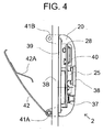
- an enlarged sectional view, of Fig. 4 of a pulse sensor unit having been shown while being cut along the band longitudinal direction
- a block circuit diagram of Fig.
- an embodiment 1 of the present invention is the wristwatch type pulse measuring apparatus having been constituted by the pulse sensor unit 2 in which the pulse sensor 25 has been accommodated in the sensor housing 20, the timepiece head 1 at least possessing the display section 16 displaying the pulse number, and a band comprising one pair of band pieces 3A and 3B, and the pulse sensor unit 2 is one having built in a power source.
- the wristwatch type pulse measuring apparatus of the embodiment 1 is one characterized in that, in the wristwatch type pulse measuring apparatus having been constituted by the pulse sensor unit 2 in which the pulse sensor 25 has been accommodated in the sensor housing 20, the timepiece head 1 at least possessing the display section 16 displaying the pulse number, and the band comprising one pair of band pieces 3A and 3B, a radio transmission section 27 is possessed in the pulse sensor unit 2 and a radio reception section 17 in the timepiece head 1, respectively, and the pulse sensor unit 2 builds in the power source.
- the pulse sensor 25 is a sensor including a light emitting element and a light receiving element. Differing from an embodiment 2 explained later, the sensor housing 20 is disposed in a back side of the band piece 3B.
- one end of the band piece 3A is attached to one band attaching part of a timepiece case 10 by a spring rod 51A
- one end of the band piece 3B is attached to one band attaching part of the timepiece case 10 by a spring rod 51B.
- the wristwatch type pulse measuring apparatus of the embodiment 1 is one having been constituted by the timepiece head 1 functioning as the pulse measuring instrument, the pulse sensor unit 2 having built in the power source, and one pair of band pieces 3A and 3B.
- the timepiece head 1 is one in which the control section 11, the clocking section 12, the storage section 13, the setting switch 14 performing a time setting, the function switch 15 performing a mode switching and the like, the display section 16, a radio reception section 17, a reception antenna 18 and a power source section 19 have been accommodated in the timepiece case 10. Further, as shown in Fig.
- the pulse sensor unit 2 is one in which a control section 21, a clocking section 22, a storage section 23, an input switch 24, the pulse sensor 25 including the light emitting element and the light receiving element, the radio transmission section 27, a transmission antenna 28 and a power source section 29 have been accommodated in the sensor housing 20.
- the timepiece case 10 of the timepiece head 1 there are accommodated a circuit block 34 having been attached to a panel frame, the liquid crystal display panel 16 and the reception antenna 18, and a battery 36 having been held by a battery frame 35 is also accommodated. And, the timepiece case 10 is sealed in its front side opening by a cover glass 31, and sealed in its back side opening by a case back 32.
- the sensor housing 20 of the pulse sensor unit 2 there are accommodated a circuit block 40 and the transmission antenna 28, which have been attached to a panel frame, the pulse sensor 25 including the light emitting element and the light receiving element, and a battery 37 having been held by a battery frame.
- the pulse sensor 25 including the light emitting element and the light receiving element, and a battery 37 having been held by a battery frame.
- an opening part having been sealed by a transparent head cover 38, and the pulse sensor 25 is disposed in a position, in the sensor housing 20, having corresponded to the above opening part.
- the pulse sensor unit 2 contacts in the head cover 38 of its pulse sensor 25 with an artery position of the wrist 8 of the user, i.e., a surface suitable for the pulse detection, and is attached while being made adjustable in the longitudinal direction.
- the sensor housing 20 of the pulse sensor unit 2 is formed in its case back 39 side with a band insertion part having possessed a 1st protrusion 41A, a 2nd protrusion 41B and a fastener 42.
- the fastener 42 is a spring member whose one end has been rotatably attached to the 1st protrusion 41A, and is one having possessed an auxiliary spring member 42A in its band piece side.
- the sensor housing 20 of the pulse sensor unit 2 is inserted into the band insertion part at a predetermined position of the band piece 3B, and the other end of the fastener 42 is locked to the 2nd protrusion 41B. Thereupon, the pulse sensor unit 2 is properly fixed to the back side of the band piece 3B and to a predetermined pulse detection position while a spring action of the auxiliary spring member 42A acts as well.
- the control section 21 calculation-processes the pulse detection signal in compliance with a program stored in the storage section 23 to thereby output the number of pulses. Subsequently, the control section 21 causes the radio transmission section 27 to operate, thereby radio-transmitting the pulse number data from the antenna 28. In the timepiece head 1, the radio reception section 17 receives the pulse number data through the antenna 18, and inputs it to the control section 11. Thereupon, the control section 11 causes the display section 16 to operate, thereby displaying the pulse number. If the user pushes again the input switch 24 of the pulse sensor unit 2, the pulse measuring mode finishes.
- the wristwatch type pulse measuring apparatus of the embodiment 1 there has been constituted such that the pulse sensor unit 2 calculation-processes the pulse detection signal of the pulse sensor 25 to the pulse number by its control section 21 to thereby transmit the pulse number from the radio transmission section 27, and the timepiece head 1 that is the pulse measuring instrument receives the pulse number by the radio reception section 17 to thereby display it by the display section 16.
- the pulse sensor unit 2 transmits the pulse detection signal of the pulse sensor 25 from the radio transmission section 27, and the timepiece head 1 that is the pulse measuring instrument receives the pulse detection signal by the radio reception section 17, thereby calculation-processing it to the pulse number and displaying the pulse number by the display section 16.
- the radio reception section 17 of the timepiece head 1 as a radio transmission/reception section
- the radio transmission section 27 of the pulse sensor unit 2 as a radio transmission section
- a switching order of the pulse measuring mode is inputted by an operation of the function switch 15 of the timepiece head, and a switching signal data of the pulse measuring mode is transmitted from the control section 11 through its transmission/reception section.
- a transmission/reception section of the pulse sensor unit 2 receives the switching signal data of the pulse measuring mode, thereby causing each constitutional element, such as the control section 21 and the pulse sensor 25, to operate.
- a sectional view, of Fig. 6, of a timepiece head having been cut along a band longitudinal direction As shown in a plan view, of Fig. 5, of a main portion of a wristwatch type pulse measuring apparatus, a sectional view, of Fig. 6, of a timepiece head having been cut along a band longitudinal direction, a sectional view, of Fig. 7, of the wristwatch type pulse measuring apparatus having been shown while being cut along the band longitudinal direction under a state having been worn to the wrist 8, enlarged sectional views, of Fig. 8 and Fig. 9, of a pulse sensor unit having been shown while being cut along the band longitudinal direction, and a block circuit diagram, of Fig.
- an embodiment 2 of the present invention is the wristwatch type pulse measuring apparatus having been constituted by the pulse sensor unit 2 in which the pulse sensor 25 has been accommodated in the sensor housing 20, the timepiece head 1 at least possessing the display section 16 displaying the pulse number, and the band comprising one pair of band pieces 3A and 3B, and the pulse sensor unit 2 is one to which an electricity is supplied from the timepiece head 1.
- the wristwatch type pulse measuring apparatus of the embodiment 2 is one characterized in that, in the wristwatch type pulse measuring apparatus having been constituted by the pulse sensor unit 2 in which the pulse sensor 25 has been accommodated in the sensor housing 20, a pulse measuring instrument, i.e., the timepiece head 1, at least possessing the liquid crystal display panel 16 displaying the pulse number, and the band comprising one pair of band pieces 3A and 3B, the radio transmission section 27 has been possessed in the pulse sensor unit 2 and the radio reception section 17 in the timepiece head 1, respectively, and a wiring 4 for power source, which supplies the electricity to the pulse sensor unit 2 from the power source section of the timepiece head 1, has been possessed in the band 3B.
- the pulse sensor 25 is the sensor including the light emitting element and the light receiving element. There is constituted such that, differing from the embodiment 1, the sensor housing 20 is disposed in a front side of the band 3B, and only a sensor face of the pulse sensor unit 2 is exposed to the back side of the band 3B.
- one end of the band piece 3A is attached to one band attaching part of the timepiece case 10 by the spring rod 51A
- one end of the band piece 3B is attached to one band attaching part of the timepiece case 10 by the spring rod 51B.
- the wristwatch type pulse measuring apparatus of the embodiment 2 is one having been constituted by the timepiece head 1 functioning as the pulse measuring instrument, the pulse sensor unit 2, one pair of band pieces 3A and 3B, and the wiring 4 for power source.
- the wiring 4 for power source is connected to the timepiece head 1 by a fixation connection part 5 and to the pulse sensor unit 2 by a position variable connection part 6, respectively.
- the timepiece head 1 is one in which the control section 11, the clocking section 12, the storage section 13, the setting switch 14 performing the time setting, the function switch 15 performing the mode switching and the like, the display section 16, the radio reception section 17, the reception antenna 18, and the power source section 19 have been accommodated in the timepiece case 10.
- the pulse sensor unit 2 is one in which the pulse sensor 25 including the light emitting element and the light receiving element, the radio transmission section 27, and the transmission antenna 28 have been accommodated in the sensor housing 20.
- the timepiece case 10 of the timepiece head 1 there are accommodated the circuit block 34 having been attached to the panel frame, a liquid crystal display panel 16 and the reception antenna 18, and the battery 36 having been held by the battery frame 35 is also accommodated. And, the timepiece case 10 is sealed in its front side opening by the cover glass 31, and sealed in its back side opening by the case back 32.
- the sensor housing 20 of the pulse sensor unit 2 is constituted by a front case 20A becoming a main body part, and a back case 20B having in its center a cylindrical protrusion part.
- the circuit block 40 having been attached to the panel frame and the transmission antenna 28
- the pulse sensor 25 including the light emitting element and the light receiving element.
- An opening part of the protrusion part of the back case 20B is sealed by the transparent head cover 38.
- the front case 20A of the sensor housing 20 is disposed in a front side of the band piece 3B , the protrusion part of the back case 20B of the sensor housing 20 is penetrated through a slit 48 of the band piece 3B, and the transparent head cover 38 is attached to the band piece 3B so as to slightly protrude from a back face of the band piece 3B.
- the slit 48 is a through-hole for exposing a front face, i.e. , sensor face, of the protrusion part of the back case 20B, that is an accommodation part of the pulse sensor 25, to a back side of the band.
- the slit 48 extends to the band piece 3B in the longitudinal direction and is formed as a rectangular through-hole. Accordingly, the pulse sensor unit 2 becomes such that an attaching position to the band piece 3B is adjustable in a range of a length of the slit 48 in the longitudinal direction.
- plural small concave parts 49 are formed at an equal interval in the longitudinal direction.
- a diameter of the concave part 49 is slightly larger than a diameter of an electrically conductive connection pin 46, and the intervals between the adjoining concave parts 49 are respectively selected to the intervals suitable for an attaching position adjustment to the band piece 3B of the pulse sensor unit 2.
- the wiring 4 for power source which supplies the drive electricity to the pulse sensor unit 2 from the electric source section 19 of the timepiece head 1, is attached to the band piece 3B while extending from end to end of the slit 48 from the fixation connection part of the timepiece head 1 that is the pulse measuring instrument.
- the wiring 4 for power source is completely embedded in the band piece 3B from the fixation connection part till one end of the slit 48, and embedded in the band piece 3B so as to be partially exposed from one end till the other end of the slit 48.
- a connection between the wiring 4 for power source and a printed circuit of the circuit block 34 of the timepiece head 1 is performed by a connection pin 44 and a conduction spring 45.
- a connection part by the connection pin 44 and the conduction spring 45 constitutes the fixation connection part 5 of Fig. 11. Incidentally, the electricity is supplied to the printed circuit of the circuit block 34 from the power source 19.
- An attachment of the wiring 4 for power source to the band piece 3B, which accompanies the partial exposure from one end to the other end of the slit 48, is performed by exposing the wiring 4 for power source to bottom faces of the concave parts 49 for position adjustment, which are formed at the equal interval in the longitudinal direction in both sides of the slit 48.
- a connection between a printed wiring of the circuit block 40 of the pulse sensor unit 2 and the wiring 4 for power source is performed by using one pair of electrically conductive connection pins 46 and one pair of electrically conductive pressurized springs 47, which have been disposed in the sensor housing 20. That is, as shown in Fig. 9, the electrically conductive connection pins 46 having been inserted into one pair of guide holes having been provided in the sensor housing 20 are connected in their rear end parts to the circuit block 40 through the electrically conductive pressurized springs 47, and are contacted in their tip parts with the wiring 4 for power source, which is exposed to a lower face of the concave part 49 while being pressurized from the electrically conductive pressurized spring 47.
- the one pair of guide holes are formed in positions adjoining both sides of the cylindrical protrusion part in the center of the back case 20B of the sensor housing 20, i.e., positions corresponding to the plural small concave parts 49 formed in both sides of the slit 48 in the front face of the band piece 3B.
- the position variable connection part (the position variable connection part 6 of Fig. 11) connecting the wiring 4 for power source to the pulse sensor unit 2 is constituted by the exposed part of the wiring 4 for power source, which has been formed in the bottom face of the concave part 49 for position adjustment, which is formed at the equal interval in the longitudinal direction in both side of the slit 48, and the one pair of electrically conductive connection pins 46 and the one pair of electrically conductive pressurized springs 47, which have been disposed in the sensor housing 20.
- a tip part of the protrusion part of the back case 20B that is a pulse sensor accommodation part of the sensor housing 20 there is formed an eaves part 52 for holding, which extends along a side face of the slit 48 in the longitudinal direction. Accordingly, the band piece 3B is nipped between the back face of the sensor housing 20 and the eaves part 52 for holding. By this, the sensor unit 2 is held by the band piece 3B, and fixed to that position. And, the connection pin 46 electrically connecting the wiring 4 for power source and the circuit block 40 of the pulse sensor unit 2 is accommodated at its tip part by the concave part 49, and contacts with its lower face while being pressurized from the exposed electrically conductive pressurized spring 47.
- the attaching position of the band piece 3B of the sensor unit 2 in the longitudinal direction becomes adjustable for every disposition interval of the concave part 49 in the range of the length of the slit 48 in the longitudinal direction.
- the pulse sensor unit 2 is made such that the transparent head cover 38 of its pulse sensor 25 contacts with the artery position of the user's wrist, i.e., the surface suitable for the pulse detection, and attached while being made adjustable in the longitudinal direction.
- a contact area between the band and the wrist 8 becomes wide, so that there is an advantage that a natural wear feeling is obtained.
- the control section 21 causes the radio transmission section 27 to operate, thereby radio-transmitting the pulse detection signal data from the antenna 28.
- the radio reception section 17 receives the pulse detection signal data through the antenna 18, thereby inputting it to the control section 11.
- the control section 11 calculation-processes the pulse detection signal data in compliance with the program stored in the storage section 13, thereby outputting the pulse number. Subsequently, the control section 11 causes the display section 16 to operate, thereby displaying the pulse number. If the user pushes again the input switch (not shown in the drawing) of the pulse sensor unit 2, the pulse measuring mode finishes.
- the pulse sensor unit 2 transmits the pulse detection signal of the pulse sensor 25 from the radio transmission section 27, and the timepiece head 1 that is the pulse measuring instrument receives the pulse detection signal by the radio reception section 17, thereby calculation-processing it to the pulse number by the control section and displaying the pulse number by the display section 16.
- the pulse sensor unit 2 calculation-processes the pulse detection signal of the pulse sensor 25 to the pulse number, thereby transmitting the pulse number from the radio transmission section 27, and to constitute such that the timepiece head 1 that is the pulse measuring instrument receives the pulse number by the radio reception section 17, thereby displaying it by the display section 16.
- the wristwatch type pulse measuring apparatus of the embodiment 2 by operating the function switch 15 of the timepiece head, it is also possible so as to perform the switching of the pulse measuring mode.
- the control section 11 controls an ON/OFF of the electronic switch by an input of the function switch 15.
- a pulse measuring apparatus comprising a pulse sensor unit in which a pulse sensor has been accommodated in a sensor housing, a pulse measuring instrument at least possessing a display section displaying a pulse number, and an arm wearing band which has been fixed to the pulse measuring instrument and to which the pulse sensor unit has been attached so as to be adjustable in a longitudinal direction, a signal of the pulse sensor unit is certainly transmitted to the pulse measuring instrument without being subjected to the electrostatic effect and without the signal transmission means being subjected to the physical adverse effect.
- a wristwatch type pulse measuring apparatus which is not subjected to the effects with respect to external environments such as static electricity and humidity, whose reliability is high, and whose portability is good as well.
Landscapes
- Health & Medical Sciences (AREA)
- Life Sciences & Earth Sciences (AREA)
- Engineering & Computer Science (AREA)
- Biophysics (AREA)
- General Health & Medical Sciences (AREA)
- Physics & Mathematics (AREA)
- Heart & Thoracic Surgery (AREA)
- Veterinary Medicine (AREA)
- Pathology (AREA)
- Biomedical Technology (AREA)
- Public Health (AREA)
- Medical Informatics (AREA)
- Molecular Biology (AREA)
- Surgery (AREA)
- Animal Behavior & Ethology (AREA)
- Cardiology (AREA)
- Physiology (AREA)
- Computer Networks & Wireless Communication (AREA)
- General Physics & Mathematics (AREA)
- Measuring Pulse, Heart Rate, Blood Pressure Or Blood Flow (AREA)
- Electric Clocks (AREA)
Abstract
Description
- The present invention relates to a pulse measuring apparatus, a so-called wristwatch type pulse measuring apparatus, which comprises a pulse sensor having been accommodated in a sensor housing, a pulse measuring instrument in which a display section processing a detection signal of the pulse sensor to thereby display a pulse number has been accommodated in a measuring instrument case, and an arm wearing band which has been fixed to a measuring instrument case and to which the unit case has been attached so as to be adjustable in a longitudinal direction.
- In order to always measure the pulse number during a motion and the like to there by make it an aim of a momentum, the wristwatch type pulse measuring apparatus has been developed. As shown in a block constitution diagram of Fig. 12, a conventional wristwatch type pulse measuring apparatus is constituted by a
pulse measuring instrument 1, apulse sensor unit 2, anarm wearing band signal line 7. Thepulse measuring instrument 1 is constituted by acontrol section 11, aclocking section 12, astorage section 13, adisplay section 16, asetting switch 14, afunction switch 15, apower source section 19, and ameasuring instrument case 10 accommodating these constitutional elements. - The
pulse sensor unit 2 is constituted by apulse sensor 25, and asensor housing 20 accommodating thepulse sensor 25. - The arm wearing band 3 comprises one pair of
band pieces band piece 3A is fixed to one band attaching part of themeasuring instrument case 10, and one end of theother band piece 3B to the other band attaching part of themeasuring instrument case 10, respectively. And, thepulse sensor unit 2 is attached to theband piece 3B so as to be adjustable in the longitudinal direction. A position adjusting function having been made so as to be capable of adjusting an attaching position of thepulse sensor unit 2 on the band is one provided while corresponding to the fact that a thickness of wrist and a position of artery of a user respectively differ, and it is a function indispensable for the wristwatch type pulse measuring apparatus. - Further, as mentioned above, in the wristwatch type pulse measuring apparatus, since the
pulse sensor unit 2 is attached onto theband piece 3B while separating by about 10 cm from thepulse measuring instrument 1, in order to transmit a detection signal of thepulse sensor 25 of thepulse sensor unit 2 to thepulse measuring instrument 1 and input it to thecontrol section 11, a signal transmission means is necessary. In Fig. 12, the signal transmission means is shown by thesignal line 7 connecting thepulse sensor unit 2 and thepulse measuring instrument 1. Hereunder, there is explained about a concrete structure of the conventional wristwatch type pulse measuring apparatus. - As disclosed in
JP-A-2002-143107 - Although this 1st conventional wristwatch type pulse measuring apparatus is one bringing about an advantage that the pulse sensor that is a pulse detecting section is adjusted for an individual user to his/her optimum position, since it is a structure in which the pulse sensor is connected to a processor section in the wristwatch case through the signal conduction means, such as metal line, having been exposed in a band side face, there is a fear that the pulse measuring apparatus malfunctions while undergoing an influence of static electricity. That is, this is because, in a case where the sensor housing has been moved along the longitudinal direction of the band, the static electricity generated by a friction between a sensor unit or the band and a clothing of the user is transmitted to a semiconductor integrated circuit constituting the pulse sensor and the processor section through the signal conduction means, such as metal line, having been exposed in the band side face, so that there is the fact that these are destroyed.
- As disclosed in
JP-A-2005-40259 - This 2nd conventional wristwatch type pulse measuring apparatus is also one bringing about the advantage that the pulse sensor that is the pulse detecting section is adjusted for an individual user to his/her optimum position. Further, since the signal cable connecting the pulse sensor and a signal processing circuit in the timepiece case are not exposed, there is also no problem of the destruction of the semiconductor integrated circuit and the like by the static electricity, which occurs in the above 1st conventional wristwatch type pulse measuring apparatus. However, if the pulse sensor is moved to a position having approached a timepiece case side, the signal cable generates slack. Thereupon, there occurs the fact that this signal cable having slack is caught by something, so that there has existed such a problem that the signal cable is impaired or a socket of the signal cable is detached from the timepiece case. In short, there has existed a problem that such a situation occurs that the signal transmission means undergoes a physical force, so that the signal from the pulse sensor becomes not transmitted to the processor section.
- A problem that the present invention ought to solve is to make such that, in a pulse measuring apparatus comprising a pulse sensor unit in which a pulse sensor has been accommodated in a sensor housing, a pulse measuring instrument possessing a display section displaying a pulse number, and an arm wearing band which has been fixed to the pulse measuring instrument and to which the pulse sensor unit has been attached so as to be adjustable in a longitudinal direction, a signal is certainly transmitted to the pulse measuring instrument without a signal transmission means from the pulse sensor unit to the pulse measuring instrument being subjected to a physical adverse effect, and without a detection signal of the pulse sensor unit being subjected to an electrostatic effect.
- In order to solve the above problem, there has been made such that, in a pulse measuring apparatus comprising a pulse sensor unit in which a pulse sensor has been accommodated in a sensor housing, a pulse measuring instrument at least possessing a display section displaying a pulse number, and an arm wearing band which has been fixed to the pulse measuring instrument and to which the pulse sensor unit has been attached so as to be capable of adjusting its position in a longitudinal direction, a radio transmission section has been possessed in the pulse sensor unit and a radio reception section in the measuring instrument, respectively, and a data is radio-transmitted from the pulse sensor unit to the measuring instrument. The data to be radio-transmitted is a pulse detection signal of the pulse sensor of the pulse sensor unit, or the pulse number having been obtained by calculation-processing the pulse detection signal by a signal processing section of the pulse sensor unit.
- Embodiments of the present invention will now be described by way of further example only and with reference to the accompanying drawings, in which:
- Fig. 1 is a plan view of a main portion of a wristwatch type pulse measuring apparatus of an
embodiment 1, where a left side half of the drawing is shown under a state in which a cover glass of a timepiece head has been removed; - Fig. 2 is a sectional view of the timepiece head constituting the wristwatch type pulse measuring apparatus of the
embodiment 1 along a band longitudinal direction; - Fig. 3 is a sectional view of the wristwatch type pulse measuring apparatus of the
embodiment 1 under a state having been worn to anarm 8 along the band longitudinal direction; - Fig. 4 is an enlarged sectional view of a pulse sensor unit constituting the wristwatch type pulse measuring apparatus of the
embodiment 1 along the band longitudinal direction; - Fig. 5 is a plan view of a main portion of a wristwatch type pulse measuring apparatus of an
embodiment 2, where a left side half of the drawing is shown under the state in which the cover glass of the timepiece head has been removed; - Fig. 6 is a sectional view of the timepiece head constituting the wristwatch type pulse measuring apparatus of the
embodiment 2 along the band longitudinal direction; - Fig. 7 is a sectional view of the wristwatch type pulse measuring apparatus of the
embodiment 2 under the state having been worn to thearm 8 along the band longitudinal direction; - Fig. 8 is an enlarged sectional view of the pulse sensor unit constituting the wristwatch type pulse measuring apparatus of the
embodiment 2 along the band longitudinal direction; - Fig. 9 is an enlarged sectional view of the pulse sensor unit constituting the wristwatch type pulse measuring apparatus of the
embodiment 2 under a state having been attached to a band, which is a sectional view along a direction perpendicular to the band longitudinal direction; - Fig. 10 is a constitution diagram of the wristwatch type pulse measuring apparatus of the
embodiment 1, in which a timepiece head as a pulse measuring instrument and the pulse sensor unit have been shown respectively by block circuits; - Fig. 11 is a constitution diagram of the wristwatch type pulse measuring apparatus of the
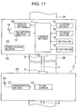
embodiment 2, in which the timepiece head as the pulse measuring instrument and the pulse sensor unit have been shown respectively by block circuits; and - Fig. 12 is a constitution diagram of a conventional wristwatch type pulse measuring apparatus, in which the timepiece head as the pulse measuring instrument and the pulse sensor unit have been shown respectively by block circuits.
- In an embodiment of a wristwatch type pulse measuring apparatus concerned with the present invention, in a wristwatch with a pulse number measuring function, which has a pulse sensor unit in which a pulse sensor has been accommodated in a sensor housing, and a timepiece case which has built in a calculation processing section calculating a pulse number by processing a signal of the pulse sensor and which has been attached to the band, a radio transmission section is possessed by the pulse sensor unit, a radio reception section is possessed by the timepiece case, and the signal of the pulse sensor of the pulse sensor unit is transmitted through the radio transmission section and the radio reception section, thereby inputting it to the calculation processing section.
- As shown in a plan view, of Fig. 1, of a main portion of a wristwatch type pulse measuring apparatus, a sectional view, of Fig. 2, of a timepiece head having been cut along a band longitudinal direction, a sectional view, of Fig. 3, of the wristwatch type pulse measuring apparatus having been shown while being cut along the band longitudinal direction under a state having been worn to a
wrist 8, an enlarged sectional view, of Fig. 4, of a pulse sensor unit having been shown while being cut along the band longitudinal direction, and a block circuit diagram, of Fig. 10, of the wristwatch type pulse measuring apparatus, anembodiment 1 of the present invention is the wristwatch type pulse measuring apparatus having been constituted by thepulse sensor unit 2 in which thepulse sensor 25 has been accommodated in thesensor housing 20, thetimepiece head 1 at least possessing thedisplay section 16 displaying the pulse number, and a band comprising one pair ofband pieces pulse sensor unit 2 is one having built in a power source. - That is, the wristwatch type pulse measuring apparatus of the
embodiment 1 is one characterized in that, in the wristwatch type pulse measuring apparatus having been constituted by thepulse sensor unit 2 in which thepulse sensor 25 has been accommodated in thesensor housing 20, thetimepiece head 1 at least possessing thedisplay section 16 displaying the pulse number, and the band comprising one pair ofband pieces radio transmission section 27 is possessed in thepulse sensor unit 2 and aradio reception section 17 in thetimepiece head 1, respectively, and thepulse sensor unit 2 builds in the power source. Thepulse sensor 25 is a sensor including a light emitting element and a light receiving element. Differing from anembodiment 2 explained later, thesensor housing 20 is disposed in a back side of theband piece 3B. - As to the band comprising one pair of
band pieces band piece 3A is attached to one band attaching part of atimepiece case 10 by aspring rod 51A, and one end of theband piece 3B is attached to one band attaching part of thetimepiece case 10 by aspring rod 51B. - If shown by a block circuit, like Fig. 10, the wristwatch type pulse measuring apparatus of the
embodiment 1 is one having been constituted by thetimepiece head 1 functioning as the pulse measuring instrument, thepulse sensor unit 2 having built in the power source, and one pair ofband pieces timepiece head 1 is one in which thecontrol section 11, theclocking section 12, thestorage section 13, thesetting switch 14 performing a time setting, thefunction switch 15 performing a mode switching and the like, thedisplay section 16, aradio reception section 17, areception antenna 18 and apower source section 19 have been accommodated in thetimepiece case 10. Further, as shown in Fig. 10, thepulse sensor unit 2 is one in which acontrol section 21, aclocking section 22, astorage section 23, aninput switch 24, thepulse sensor 25 including the light emitting element and the light receiving element, theradio transmission section 27, atransmission antenna 28 and apower source section 29 have been accommodated in thesensor housing 20. - As shown in Fig. 1 and Fig. 2, in the
timepiece case 10 of thetimepiece head 1, there are accommodated acircuit block 34 having been attached to a panel frame, the liquidcrystal display panel 16 and thereception antenna 18, and abattery 36 having been held by abattery frame 35 is also accommodated. And, thetimepiece case 10 is sealed in its front side opening by acover glass 31, and sealed in its back side opening by a case back 32. - As shown in Fig. 3 and Fig. 4, in the
sensor housing 20 of thepulse sensor unit 2, there are accommodated acircuit block 40 and thetransmission antenna 28, which have been attached to a panel frame, thepulse sensor 25 including the light emitting element and the light receiving element, and abattery 37 having been held by a battery frame. In a central part of thesensor housing 20, there is formed an opening part having been sealed by atransparent head cover 38, and thepulse sensor 25 is disposed in a position, in thesensor housing 20, having corresponded to the above opening part. - As shown in Fig. 1 and Fig. 3, in the wristwatch type pulse measuring apparatus of the
embodiment 1, thepulse sensor unit 2 contacts in thehead cover 38 of itspulse sensor 25 with an artery position of thewrist 8 of the user, i.e., a surface suitable for the pulse detection, and is attached while being made adjustable in the longitudinal direction. - As shown in Fig. 3 and Fig. 4, the sensor housing 20 of the
pulse sensor unit 2 is formed in itscase back 39 side with a band insertion part having possessed a1st protrusion 41A, a2nd protrusion 41B and afastener 42. Thefastener 42 is a spring member whose one end has been rotatably attached to the1st protrusion 41A, and is one having possessed anauxiliary spring member 42A in its band piece side. The sensor housing 20 of thepulse sensor unit 2 is inserted into the band insertion part at a predetermined position of theband piece 3B, and the other end of thefastener 42 is locked to the2nd protrusion 41B. Thereupon, thepulse sensor unit 2 is properly fixed to the back side of theband piece 3B and to a predetermined pulse detection position while a spring action of theauxiliary spring member 42A acts as well. - If the user who has worn the wristwatch type pulse measuring apparatus of the
embodiment 1 on the arm pushes theinput switch 24 of thepulse sensor unit 2, it enters to a pulse measuring mode. That is, thepulse sensor unit 25 outputs a pulse detection signal to thereby input it to thecontrol section 21. Thereupon, thecontrol section 21 calculation-processes the pulse detection signal in compliance with a program stored in thestorage section 23 to thereby output the number of pulses. Subsequently, thecontrol section 21 causes theradio transmission section 27 to operate, thereby radio-transmitting the pulse number data from theantenna 28. In thetimepiece head 1, theradio reception section 17 receives the pulse number data through theantenna 18, and inputs it to thecontrol section 11. Thereupon, thecontrol section 11 causes thedisplay section 16 to operate, thereby displaying the pulse number. If the user pushes again theinput switch 24 of thepulse sensor unit 2, the pulse measuring mode finishes. - As mentioned above, in the wristwatch type pulse measuring apparatus of the
embodiment 1, there has been constituted such that thepulse sensor unit 2 calculation-processes the pulse detection signal of thepulse sensor 25 to the pulse number by itscontrol section 21 to thereby transmit the pulse number from theradio transmission section 27, and thetimepiece head 1 that is the pulse measuring instrument receives the pulse number by theradio reception section 17 to thereby display it by thedisplay section 16. - However, in the wristwatch type pulse measuring apparatus of the
embodiment 1, it is also possible to constitute such that thepulse sensor unit 2 transmits the pulse detection signal of thepulse sensor 25 from theradio transmission section 27, and thetimepiece head 1 that is the pulse measuring instrument receives the pulse detection signal by theradio reception section 17, thereby calculation-processing it to the pulse number and displaying the pulse number by thedisplay section 16. - By the way, by constituting the
radio reception section 17 of thetimepiece head 1 as a radio transmission/reception section, and constituting theradio transmission section 27 of thepulse sensor unit 2 as a radio transmission section, there can be also realized a switching of the pulse measuring mode having been made so as to control a starting of thepulse sensor unit 2 from thetimepiece head 1. In this case, a switching order of the pulse measuring mode is inputted by an operation of thefunction switch 15 of the timepiece head, and a switching signal data of the pulse measuring mode is transmitted from thecontrol section 11 through its transmission/reception section. And, it follows that a transmission/reception section of thepulse sensor unit 2 receives the switching signal data of the pulse measuring mode, thereby causing each constitutional element, such as thecontrol section 21 and thepulse sensor 25, to operate. - As shown in a plan view, of Fig. 5, of a main portion of a wristwatch type pulse measuring apparatus, a sectional view, of Fig. 6, of a timepiece head having been cut along a band longitudinal direction, a sectional view, of Fig. 7, of the wristwatch type pulse measuring apparatus having been shown while being cut along the band longitudinal direction under a state having been worn to the
wrist 8, enlarged sectional views, of Fig. 8 and Fig. 9, of a pulse sensor unit having been shown while being cut along the band longitudinal direction, and a block circuit diagram, of Fig. 11, of the wristwatch type pulse measuring apparatus, anembodiment 2 of the present invention is the wristwatch type pulse measuring apparatus having been constituted by thepulse sensor unit 2 in which thepulse sensor 25 has been accommodated in thesensor housing 20, thetimepiece head 1 at least possessing thedisplay section 16 displaying the pulse number, and the band comprising one pair ofband pieces pulse sensor unit 2 is one to which an electricity is supplied from thetimepiece head 1. - That is, the wristwatch type pulse measuring apparatus of the
embodiment 2 is one characterized in that, in the wristwatch type pulse measuring apparatus having been constituted by thepulse sensor unit 2 in which thepulse sensor 25 has been accommodated in thesensor housing 20, a pulse measuring instrument, i.e., thetimepiece head 1, at least possessing the liquidcrystal display panel 16 displaying the pulse number, and the band comprising one pair ofband pieces radio transmission section 27 has been possessed in thepulse sensor unit 2 and theradio reception section 17 in thetimepiece head 1, respectively, and awiring 4 for power source, which supplies the electricity to thepulse sensor unit 2 from the power source section of thetimepiece head 1, has been possessed in theband 3B. Thepulse sensor 25 is the sensor including the light emitting element and the light receiving element. There is constituted such that, differing from theembodiment 1, thesensor housing 20 is disposed in a front side of theband 3B, and only a sensor face of thepulse sensor unit 2 is exposed to the back side of theband 3B. - As to the band comprising one pair of
band pieces band piece 3A is attached to one band attaching part of thetimepiece case 10 by thespring rod 51A, and one end of theband piece 3B is attached to one band attaching part of thetimepiece case 10 by thespring rod 51B. - As shown by a block circuit, like Fig. 11, the wristwatch type pulse measuring apparatus of the
embodiment 2 is one having been constituted by thetimepiece head 1 functioning as the pulse measuring instrument, thepulse sensor unit 2, one pair ofband pieces wiring 4 for power source. Thewiring 4 for power source is connected to thetimepiece head 1 by afixation connection part 5 and to thepulse sensor unit 2 by a positionvariable connection part 6, respectively. Thetimepiece head 1 is one in which thecontrol section 11, theclocking section 12, thestorage section 13, the settingswitch 14 performing the time setting, thefunction switch 15 performing the mode switching and the like, thedisplay section 16, theradio reception section 17, thereception antenna 18, and thepower source section 19 have been accommodated in thetimepiece case 10. Further, thepulse sensor unit 2 is one in which thepulse sensor 25 including the light emitting element and the light receiving element, theradio transmission section 27, and thetransmission antenna 28 have been accommodated in thesensor housing 20. - As shown in Fig. 5 and Fig. 6, in the
timepiece case 10 of thetimepiece head 1, there are accommodated thecircuit block 34 having been attached to the panel frame, a liquidcrystal display panel 16 and thereception antenna 18, and thebattery 36 having been held by thebattery frame 35 is also accommodated. And, thetimepiece case 10 is sealed in its front side opening by thecover glass 31, and sealed in its back side opening by the case back 32. - As shown in Fig. 7 to Fig. 9, the
sensor housing 20 of thepulse sensor unit 2 is constituted by afront case 20A becoming a main body part, and aback case 20B having in its center a cylindrical protrusion part. In thefront case 20A, there are accommodated thecircuit block 40 having been attached to the panel frame and thetransmission antenna 28 and, in theback case 20B, there is accommodated thepulse sensor 25 including the light emitting element and the light receiving element. An opening part of the protrusion part of theback case 20B is sealed by thetransparent head cover 38. - As to the
sensor housing 20, thefront case 20A of thesensor housing 20 is disposed in a front side of theband piece 3B , the protrusion part of theback case 20B of thesensor housing 20 is penetrated through aslit 48 of theband piece 3B, and thetransparent head cover 38 is attached to theband piece 3B so as to slightly protrude from a back face of theband piece 3B. Theslit 48 is a through-hole for exposing a front face, i.e. , sensor face, of the protrusion part of theback case 20B, that is an accommodation part of thepulse sensor 25, to a back side of the band. - The
slit 48 extends to theband piece 3B in the longitudinal direction and is formed as a rectangular through-hole. Accordingly, thepulse sensor unit 2 becomes such that an attaching position to theband piece 3B is adjustable in a range of a length of theslit 48 in the longitudinal direction. - In both sides of the
slit 48 in a front face of theband piece 3B, plural smallconcave parts 49 are formed at an equal interval in the longitudinal direction. A diameter of theconcave part 49 is slightly larger than a diameter of an electricallyconductive connection pin 46, and the intervals between the adjoiningconcave parts 49 are respectively selected to the intervals suitable for an attaching position adjustment to theband piece 3B of thepulse sensor unit 2. - The
wiring 4 for power source, which supplies the drive electricity to thepulse sensor unit 2 from theelectric source section 19 of thetimepiece head 1, is attached to theband piece 3B while extending from end to end of theslit 48 from the fixation connection part of thetimepiece head 1 that is the pulse measuring instrument. Thewiring 4 for power source is completely embedded in theband piece 3B from the fixation connection part till one end of theslit 48, and embedded in theband piece 3B so as to be partially exposed from one end till the other end of theslit 48. A connection between thewiring 4 for power source and a printed circuit of thecircuit block 34 of thetimepiece head 1 is performed by aconnection pin 44 and aconduction spring 45. A connection part by theconnection pin 44 and theconduction spring 45 constitutes thefixation connection part 5 of Fig. 11. Incidentally, the electricity is supplied to the printed circuit of thecircuit block 34 from thepower source 19. - An attachment of the
wiring 4 for power source to theband piece 3B, which accompanies the partial exposure from one end to the other end of theslit 48, is performed by exposing thewiring 4 for power source to bottom faces of theconcave parts 49 for position adjustment, which are formed at the equal interval in the longitudinal direction in both sides of theslit 48. - A connection between a printed wiring of the
circuit block 40 of thepulse sensor unit 2 and thewiring 4 for power source is performed by using one pair of electrically conductive connection pins 46 and one pair of electrically conductivepressurized springs 47, which have been disposed in thesensor housing 20. That is, as shown in Fig. 9, the electrically conductive connection pins 46 having been inserted into one pair of guide holes having been provided in thesensor housing 20 are connected in their rear end parts to thecircuit block 40 through the electrically conductivepressurized springs 47, and are contacted in their tip parts with thewiring 4 for power source, which is exposed to a lower face of theconcave part 49 while being pressurized from the electrically conductivepressurized spring 47. The one pair of guide holes are formed in positions adjoining both sides of the cylindrical protrusion part in the center of theback case 20B of thesensor housing 20, i.e., positions corresponding to the plural smallconcave parts 49 formed in both sides of theslit 48 in the front face of theband piece 3B. - In short, the position variable connection part (the position
variable connection part 6 of Fig. 11) connecting thewiring 4 for power source to thepulse sensor unit 2 is constituted by the exposed part of thewiring 4 for power source, which has been formed in the bottom face of theconcave part 49 for position adjustment, which is formed at the equal interval in the longitudinal direction in both side of theslit 48, and the one pair of electrically conductive connection pins 46 and the one pair of electrically conductivepressurized springs 47, which have been disposed in thesensor housing 20. - In a tip part of the protrusion part of the
back case 20B that is a pulse sensor accommodation part of thesensor housing 20, there is formed an eaves part 52 for holding, which extends along a side face of theslit 48 in the longitudinal direction. Accordingly, theband piece 3B is nipped between the back face of thesensor housing 20 and the eaves part 52 for holding. By this, thesensor unit 2 is held by theband piece 3B, and fixed to that position. And, theconnection pin 46 electrically connecting thewiring 4 for power source and thecircuit block 40 of thepulse sensor unit 2 is accommodated at its tip part by theconcave part 49, and contacts with its lower face while being pressurized from the exposed electrically conductivepressurized spring 47. In this manner, while holding the connection between thewiring 4 for power source and thecircuit block 40 of thepulse sensor unit 2, the attaching position of theband piece 3B of thesensor unit 2 in the longitudinal direction becomes adjustable for every disposition interval of theconcave part 49 in the range of the length of theslit 48 in the longitudinal direction. - In the wristwatch type pulse measuring apparatus of the
embodiment 2, thepulse sensor unit 2 is made such that thetransparent head cover 38 of itspulse sensor 25 contacts with the artery position of the user's wrist, i.e., the surface suitable for the pulse detection, and attached while being made adjustable in the longitudinal direction. In comparison with theembodiment 1, in the wristwatch type pulse measuring apparatus of theembodiment 2, a contact area between the band and thewrist 8 becomes wide, so that there is an advantage that a natural wear feeling is obtained. - In one variation, if the user who has worn the wristwatch type pulse measuring apparatus of the
embodiment 2 to the arm pushes an input switch (not shown in the drawing) of thepulse sensor unit 2, it enters into the pulse measuring mode. That is, thepulse sensor 25 outputs the pulse detection signal, thereby inputting it to thecontrol section 21. Thereupon, thecontrol section 21 causes theradio transmission section 27 to operate, thereby radio-transmitting the pulse detection signal data from theantenna 28. In thetimepiece head 1, theradio reception section 17 receives the pulse detection signal data through theantenna 18, thereby inputting it to thecontrol section 11. Thereupon, thecontrol section 11 calculation-processes the pulse detection signal data in compliance with the program stored in thestorage section 13, thereby outputting the pulse number. Subsequently, thecontrol section 11 causes thedisplay section 16 to operate, thereby displaying the pulse number. If the user pushes again the input switch (not shown in the drawing) of thepulse sensor unit 2, the pulse measuring mode finishes. - As mentioned above, in the wristwatch type pulse measuring apparatus of the
embodiment 2, there has been constituted such that thepulse sensor unit 2 transmits the pulse detection signal of thepulse sensor 25 from theradio transmission section 27, and thetimepiece head 1 that is the pulse measuring instrument receives the pulse detection signal by theradio reception section 17, thereby calculation-processing it to the pulse number by the control section and displaying the pulse number by thedisplay section 16. - However, in the wristwatch type pulse measuring apparatus of the
embodiment 2, it is also possible to make such that thepulse sensor unit 2 calculation-processes the pulse detection signal of thepulse sensor 25 to the pulse number, thereby transmitting the pulse number from theradio transmission section 27, and to constitute such that thetimepiece head 1 that is the pulse measuring instrument receives the pulse number by theradio reception section 17, thereby displaying it by thedisplay section 16. - By the way, in the wristwatch type pulse measuring apparatus of the
embodiment 2, by operating thefunction switch 15 of the timepiece head, it is also possible so as to perform the switching of the pulse measuring mode. For example, by inserting an electronic switch into thewiring 4 for power source, there can be realized by constituting such that thecontrol section 11 controls an ON/OFF of the electronic switch by an input of thefunction switch 15. - By the present invention, there has been made possible such that, in a pulse measuring apparatus comprising a pulse sensor unit in which a pulse sensor has been accommodated in a sensor housing, a pulse measuring instrument at least possessing a display section displaying a pulse number, and an arm wearing band which has been fixed to the pulse measuring instrument and to which the pulse sensor unit has been attached so as to be adjustable in a longitudinal direction, a signal of the pulse sensor unit is certainly transmitted to the pulse measuring instrument without being subjected to the electrostatic effect and without the signal transmission means being subjected to the physical adverse effect. Accordingly, by the present invention, there has been provided a wristwatch type pulse measuring apparatus which is not subjected to the effects with respect to external environments such as static electricity and humidity, whose reliability is high, and whose portability is good as well.
- It should be noted that the term "wristwatch" in the foregoing description neither precludes nor requires a time-keeping or displaying function.
- The aforegoing description has been given by way of example only and it will be appreciated by a person skilled in the art that modifications can be made without departing from the scope of the present invention.
Claims (9)
- A pulse measuring apparatus comprising:a pulse sensor unit in which a pulse sensor has been accommodated in a sensor housing;a pulse measuring instrument at least possessing a display section displaying a pulse number; andan arm wearing band which has been fixed to the pulse measuring instrument and to which the pulse sensor unit has been attached so as to be capable of adjusting its position in a longitudinal direction characterized in that a radio transmission section has been possessed in the pulse sensor unit and a radio reception section in the pulse measuring instrument, respectively.
- A pulse measuring apparatus according to claim 1; wherein the pulse sensor unit is one which transmits a pulse detection signal of the pulse sensor, and the pulse measuring instrument is one which receives the pulse detection signal by the radio reception section and calculation-processes it to a pulse number by its signal processing section, thereby displaying the pulse number by the display section.
- A pulse measuring apparatus according to claim 1;
wherein the pulse sensor unit is one which calculation-processes a pulse detection signal of the pulse sensor to a pulse number by its signal processing section to thereby transmit the pulse number from the radio transmission section, and the pulse measuring instrument is one which receives the pulse number by the radio reception section, thereby displaying it by the display section. - A pulse measuring apparatus according to any one of the preceding claims, wherein a power source of the pulse sensor unit is a battery having been accommodated in the sensor housing.
- A pulse measuring apparatus according to any one of claims 1 to 3,wherein a drive voltage is supplied to the pulse sensor by a wiring for power source, which has been provided in the band, from a battery accommodated in a measuring instrument case.
- A pulse measuring apparatus according to claim 5, wherein the wiring for power source comprises a pair of embedded lines having exposure parts which have been partially exposed in an attaching position of the pulse sensor unit, and movable power source terminals of the pulse sensor unit are disposed so as to electrically contact with the exposure parts of the wiring for power source.
- A pulse measuring apparatus according to claim 6, wherein the attaching position of the pulse sensor unit is a slit having been formed in the band, and the wiring for power source has the exposure parts in bottom faces of concave parts for position adjustment, which are formed in both sides of the slit in a longitudinal direction.
- A pulse measuring apparatus according to claim 6 or claim 7
wherein the movable power source terminals of the pulse sensor unit comprise a pair of electrically conductive connection pins and a pair of electrically conductive pressurized springs, which have been disposed in the sensor housing. - A pulse measuring apparatus according to any one of the preceding claims, wherein there has been provided an input means which instructs a starting and a stopping of a pulse detection to the pulse sensor unit.
Applications Claiming Priority (1)
| Application Number | Priority Date | Filing Date | Title |
|---|---|---|---|
| JP2006039477A JP4813919B2 (en) | 2006-02-16 | 2006-02-16 | Pulse measuring device |
Publications (1)
| Publication Number | Publication Date |
|---|---|
| EP1820443A1 true EP1820443A1 (en) | 2007-08-22 |
Family
ID=38007320
Family Applications (1)
| Application Number | Title | Priority Date | Filing Date |
|---|---|---|---|
| EP07250612A Withdrawn EP1820443A1 (en) | 2006-02-16 | 2007-02-15 | Pulse measuring apparatus |
Country Status (3)
| Country | Link |
|---|---|
| US (1) | US20070191718A1 (en) |
| EP (1) | EP1820443A1 (en) |
| JP (1) | JP4813919B2 (en) |
Cited By (1)
| Publication number | Priority date | Publication date | Assignee | Title |
|---|---|---|---|---|
| NL1041276A (en) * | 2015-04-16 | 2016-10-19 | Scint B V | Method and device for measuring a health status and physiological parameters of an user at rest and under movement |
Families Citing this family (32)
| Publication number | Priority date | Publication date | Assignee | Title |
|---|---|---|---|---|
| US8652040B2 (en) | 2006-12-19 | 2014-02-18 | Valencell, Inc. | Telemetric apparatus for health and environmental monitoring |
| US8157730B2 (en) | 2006-12-19 | 2012-04-17 | Valencell, Inc. | Physiological and environmental monitoring systems and methods |
| WO2008078719A1 (en) | 2006-12-27 | 2008-07-03 | Bridgestone Corporation | Pipe fitting and hose |
| US8251903B2 (en) | 2007-10-25 | 2012-08-28 | Valencell, Inc. | Noninvasive physiological analysis using excitation-sensor modules and related devices and methods |
| JP4820961B2 (en) * | 2008-05-16 | 2011-11-24 | 株式会社最新松本技研 | Pulse abnormality detection device |
| US9750462B2 (en) | 2009-02-25 | 2017-09-05 | Valencell, Inc. | Monitoring apparatus and methods for measuring physiological and/or environmental conditions |
| US8700111B2 (en) | 2009-02-25 | 2014-04-15 | Valencell, Inc. | Light-guiding devices and monitoring devices incorporating same |
| US8788002B2 (en) | 2009-02-25 | 2014-07-22 | Valencell, Inc. | Light-guiding devices and monitoring devices incorporating same |
| US8888701B2 (en) | 2011-01-27 | 2014-11-18 | Valencell, Inc. | Apparatus and methods for monitoring physiological data during environmental interference |
| EP2687998B1 (en) | 2011-03-14 | 2015-12-09 | Nikon Corporation | Information terminal, information providing server, and control program |
| US9427191B2 (en) | 2011-07-25 | 2016-08-30 | Valencell, Inc. | Apparatus and methods for estimating time-state physiological parameters |
| EP3222210B1 (en) | 2011-08-02 | 2024-09-25 | Yukka Magic LLC | Systems and methods for variable filter adjustment by heart rate metric feedback |
| US12156744B2 (en) | 2011-11-29 | 2024-12-03 | Koninklijke Philips N.V. | Tailorable sensor device for physiological parameter sensing |
| CN107041735B (en) * | 2012-07-17 | 2020-05-19 | 北京超思电子技术有限责任公司 | Wrist strap formula physiological information monitoring devices |
| EP2747198A1 (en) * | 2012-12-21 | 2014-06-25 | The Swatch Group Research and Development Ltd. | Antenna assembly for a time-piece |
| WO2014116942A2 (en) | 2013-01-28 | 2014-07-31 | Valencell, Inc. | Physiological monitoring devices having sensing elements decoupled from body motion |
| US9465365B2 (en) * | 2013-10-25 | 2016-10-11 | Mark Nichol | Electronic device capable of being coupled to a wristwatch |
| US9488964B2 (en) * | 2014-06-27 | 2016-11-08 | Apple Inc. | Methods for maintaining accurate timing information on portable electronic devices |
| US20160029898A1 (en) | 2014-07-30 | 2016-02-04 | Valencell, Inc. | Physiological Monitoring Devices and Methods Using Optical Sensors |
| US10536768B2 (en) | 2014-08-06 | 2020-01-14 | Valencell, Inc. | Optical physiological sensor modules with reduced signal noise |
| US9575466B1 (en) | 2014-09-03 | 2017-02-21 | Fossil Group, Inc. | Sensor-enabled fashion timepiece |
| US9794653B2 (en) | 2014-09-27 | 2017-10-17 | Valencell, Inc. | Methods and apparatus for improving signal quality in wearable biometric monitoring devices |
| KR102547796B1 (en) * | 2014-10-15 | 2023-06-26 | 삼성전자주식회사 | Detachable living body signal complex sensor and method for detecting information of the living body using the same |
| US10076252B2 (en) * | 2015-04-02 | 2018-09-18 | Microsoft Technology Licensing, Llc | Sizable wrist-worn pressure sensing device |
| EP3304217A4 (en) * | 2015-06-05 | 2019-01-02 | Strebe, Matthew | Multiple device wrist band |
| US10945618B2 (en) | 2015-10-23 | 2021-03-16 | Valencell, Inc. | Physiological monitoring devices and methods for noise reduction in physiological signals based on subject activity type |
| EP3344127A4 (en) | 2015-10-23 | 2018-07-25 | Valencell, Inc. | Physiological monitoring devices and methods that identify subject activity type |
| US10966662B2 (en) | 2016-07-08 | 2021-04-06 | Valencell, Inc. | Motion-dependent averaging for physiological metric estimating systems and methods |
| CN111867449B (en) * | 2018-03-09 | 2022-03-29 | 华为技术有限公司 | Method and terminal device for measuring human physiological parameters |
| EP4009120B1 (en) * | 2020-12-03 | 2026-02-25 | Casio Computer Co., Ltd. | Detection device and body-worn device |
| CN114721247B (en) * | 2020-12-22 | 2024-04-30 | Oppo广东移动通信有限公司 | Wearable device |
| US20240324956A1 (en) * | 2023-03-29 | 2024-10-03 | Oxti Pte Ltd | Detachable detection device |
Citations (4)
| Publication number | Priority date | Publication date | Assignee | Title |
|---|---|---|---|---|
| US3362350A (en) * | 1965-04-05 | 1968-01-09 | Marx & Co Louis | Racing toy |
| US5310355A (en) * | 1993-03-09 | 1994-05-10 | Irmgard Dannatt | Strip lighting assembly |
| US5810736A (en) * | 1995-08-22 | 1998-09-22 | Pail; Opher | Wrist pulse monitor |
| US20040138568A1 (en) * | 2003-01-15 | 2004-07-15 | Salutron, Inc. | Ultrasonic monitor for measuring heart rate and blood flow rate |
Family Cites Families (15)
| Publication number | Priority date | Publication date | Assignee | Title |
|---|---|---|---|---|
| US4086916A (en) * | 1975-09-19 | 1978-05-02 | Joseph J. Cayre | Cardiac monitor wristwatch |
| JPS5877494A (en) * | 1981-10-26 | 1983-05-10 | 日本電気株式会社 | Tape cutter |
| JPS6265595A (en) * | 1985-09-17 | 1987-03-24 | Furuno Electric Co Ltd | Electrode division type vibrator using ceramic piezoelectric element |
| JPS6446004A (en) * | 1987-08-12 | 1989-02-20 | Toshiba Corp | Hydraulic fluid monitor |
| CA2031759A1 (en) * | 1989-12-29 | 1991-06-30 | Ronald P. Willett | Sensor applicator |
| JP3041401B2 (en) * | 1990-09-19 | 2000-05-15 | セイコーインスツルメンツ株式会社 | Pulse wave measurement equipment |
| JP2000316858A (en) * | 1999-03-11 | 2000-11-21 | Seiko Instruments Inc | Pulse wave detection device, manufacturing method thereof, and wrist portable device |
| JP3626625B2 (en) * | 1999-04-21 | 2005-03-09 | セイコーインスツル株式会社 | Pulse wave detector |
| JP2001292971A (en) * | 2000-04-13 | 2001-10-23 | Nippon Seimitsu Sokki Kk | Pulse rate meter |
| TW524671B (en) * | 2000-06-14 | 2003-03-21 | Koninkl Philips Electronics Nv | Device for monitoring a vital sign |
| JP3722203B2 (en) * | 2000-06-14 | 2005-11-30 | 株式会社デンソー | Pulse wave sensor |
| JP2003079588A (en) * | 2001-09-10 | 2003-03-18 | Tsugio Nagai | Sleep cycle alarm clock |
| JP4363157B2 (en) * | 2002-11-29 | 2009-11-11 | オムロンヘルスケア株式会社 | Pulse wave measuring device |
| US7526327B2 (en) * | 2003-06-04 | 2009-04-28 | Eta Sa Manufacture Horlogère Suisse | Instrument having optical device measuring a physiological quantity and means for transmitting and/or receiving data |
| JP2005040259A (en) * | 2003-07-25 | 2005-02-17 | Waatekkusu:Kk | Pulse wave detector and pulse rate detector |
-
2006
- 2006-02-16 JP JP2006039477A patent/JP4813919B2/en not_active Expired - Fee Related
-
2007
- 2007-02-06 US US11/703,012 patent/US20070191718A1/en not_active Abandoned
- 2007-02-15 EP EP07250612A patent/EP1820443A1/en not_active Withdrawn
Patent Citations (4)
| Publication number | Priority date | Publication date | Assignee | Title |
|---|---|---|---|---|
| US3362350A (en) * | 1965-04-05 | 1968-01-09 | Marx & Co Louis | Racing toy |
| US5310355A (en) * | 1993-03-09 | 1994-05-10 | Irmgard Dannatt | Strip lighting assembly |
| US5810736A (en) * | 1995-08-22 | 1998-09-22 | Pail; Opher | Wrist pulse monitor |
| US20040138568A1 (en) * | 2003-01-15 | 2004-07-15 | Salutron, Inc. | Ultrasonic monitor for measuring heart rate and blood flow rate |
Cited By (1)
| Publication number | Priority date | Publication date | Assignee | Title |
|---|---|---|---|---|
| NL1041276A (en) * | 2015-04-16 | 2016-10-19 | Scint B V | Method and device for measuring a health status and physiological parameters of an user at rest and under movement |
Also Published As
| Publication number | Publication date |
|---|---|
| JP4813919B2 (en) | 2011-11-09 |
| JP2007215749A (en) | 2007-08-30 |
| US20070191718A1 (en) | 2007-08-16 |
Similar Documents
| Publication | Publication Date | Title |
|---|---|---|
| US20070191718A1 (en) | Pulse measuring apparatus | |
| EP0653182B1 (en) | Portable measuring apparatus | |
| KR100330351B1 (en) | Wrist instrument and electronic apparatus | |
| US4586827A (en) | Information system | |
| US10039186B2 (en) | Stretchable and flexible electrical substrate interconnections | |
| JP2001167651A (en) | Electronic information equipment | |
| US20180020786A1 (en) | Connected bracelet | |
| JPH10155753A (en) | Structure of heart rate measuring apparatus | |
| GB2298581A (en) | A socket for an anti-static strap | |
| KR100283647B1 (en) | Detection device, manufacturing method of this detection device and electronic equipment using the detection device | |
| JP2013031597A (en) | Biological information measuring device, and method for measuring biological information | |
| US11497444B2 (en) | Biological information measurement device | |
| CN114721247B (en) | Wearable device | |
| US7865329B2 (en) | Electronic pedometer | |
| US7799978B2 (en) | Tuner mounting device | |
| US20170340275A1 (en) | Wearable device | |
| JP2009099521A (en) | Tilted vibration sensor and portable apparatus using the same, and crime prevention system | |
| KR100525871B1 (en) | Clip connector | |
| KR20180027299A (en) | Health band terminal | |
| JP7824795B2 (en) | Bone conduction earphone unit and bone conduction testing device | |
| CN224235393U (en) | Wearable device and wearable device system | |
| JP2003159223A (en) | Living body signal detection device | |
| JP3535916B2 (en) | Wrist-mounted pulse wave measuring device | |
| JP2001057965A (en) | Portable pulse wave measuring device | |
| JPH09113569A (en) | Failure detection method between terminals in connector part |
Legal Events
| Date | Code | Title | Description |
|---|---|---|---|
| PUAI | Public reference made under article 153(3) epc to a published international application that has entered the european phase |
Free format text: ORIGINAL CODE: 0009012 |
|
| AK | Designated contracting states |
Kind code of ref document: A1 Designated state(s): AT BE BG CH CY CZ DE DK EE ES FI FR GB GR HU IE IS IT LI LT LU LV MC NL PL PT RO SE SI SK TR |
|
| AX | Request for extension of the european patent |
Extension state: AL BA HR MK YU |
|
| 17P | Request for examination filed |
Effective date: 20080222 |
|
| 17Q | First examination report despatched |
Effective date: 20080326 |
|
| AKX | Designation fees paid |
Designated state(s): DE FR GB |
|
| D17P | Request for examination filed (deleted) | ||
| REG | Reference to a national code |
Ref country code: DE Ref legal event code: 8566 |
|
| STAA | Information on the status of an ep patent application or granted ep patent |
Free format text: STATUS: THE APPLICATION IS DEEMED TO BE WITHDRAWN |
|
| 18D | Application deemed to be withdrawn |
Effective date: 20080223 |