EP1820420A1 - Built-in cupboard elements for storage - Google Patents
Built-in cupboard elements for storage Download PDFInfo
- Publication number
- EP1820420A1 EP1820420A1 EP06110065A EP06110065A EP1820420A1 EP 1820420 A1 EP1820420 A1 EP 1820420A1 EP 06110065 A EP06110065 A EP 06110065A EP 06110065 A EP06110065 A EP 06110065A EP 1820420 A1 EP1820420 A1 EP 1820420A1
- Authority
- EP
- European Patent Office
- Prior art keywords
- cabinet
- pivot
- mounting part
- lever
- bearing
- Prior art date
- Legal status (The legal status is an assumption and is not a legal conclusion. Google has not performed a legal analysis and makes no representation as to the accuracy of the status listed.)
- Granted
Links
Images


Classifications
-
- A—HUMAN NECESSITIES
- A47—FURNITURE; DOMESTIC ARTICLES OR APPLIANCES; COFFEE MILLS; SPICE MILLS; SUCTION CLEANERS IN GENERAL
- A47B—TABLES; DESKS; OFFICE FURNITURE; CABINETS; DRAWERS; GENERAL DETAILS OF FURNITURE
- A47B51/00—Cabinets with means for moving compartments up and down
-
- A—HUMAN NECESSITIES
- A47—FURNITURE; DOMESTIC ARTICLES OR APPLIANCES; COFFEE MILLS; SPICE MILLS; SUCTION CLEANERS IN GENERAL
- A47B—TABLES; DESKS; OFFICE FURNITURE; CABINETS; DRAWERS; GENERAL DETAILS OF FURNITURE
- A47B46/00—Cabinets, racks or shelf units, having one or more surfaces adapted to be brought into position for use by extending or pivoting
- A47B46/005—Cabinets, racks or shelf units, having one or more surfaces adapted to be brought into position for use by extending or pivoting by displacement in a vertical plane; by rotating about a horizontal axis
Abstract
Description
Die vorliegende Erfindung bezieht sich auf ein Schrankeinbauteil mit Ablagefach, welches in einen Oberschrank einsetzbar ist und von einer oberen, in den Oberschrank eingefahrenen Position in eine aus dem Oberschrank ausgefahrene und nach unten versetzte Position ausschwenkbar ist, wobei beidseits des Schrankeinbauteils zwei parallel ausgerichtete Schwenkhebel angebracht sind, die einerseits über erste Schwenklager am Oberschrank anlenkbar sind und andererseits über zweite Schwenklager am Schrankeinbauteil angelenkt sind, und mindestens ein Federelement angebracht ist, das einerseits an einem der Schwenkhebel in einem Anlenkpunkt angelenkt und andererseits am Oberschrank gehalten ist.The present invention relates to a cabinet component with storage compartment, which can be inserted into a wall unit and can be swung out of an upper, retracted into the upper cabinet position in an extended from the upper cabinet and down offset position, mounted on both sides of the cabinet insert part two parallel pivot lever are, on the one hand via the first pivot bearing on the wall unit are articulated and on the other hand articulated via second pivot bearing on the cabinet component, and at least one spring element is mounted, which is articulated on the one hand to one of the pivot lever in a pivot point and the other hand held on the top cabinet.
Derartige Schrankeinbauteile sind bekannt. Sie werden insbesondere in Oberschränken von Küchen eingesetzt, die oftmals praktisch bis zur Decke reichen, so dass die Zugänglichkeit dieser oberen Bereiche der Oberschränke für eine eine Normalgrösse aufweisende Person ohne Steighilfen nicht möglich ist. Mit diesen Schrankeinbauteilen hat man die Möglichkeit, die darin gehaltenen Ablagefächer durch Herunterschwenken in eine tiefere Lage zu bringen, so dass die Zugänglichkeit wesentlich verbessert wird.Such cabinet installation parts are known. They are used in particular in upper cabinets of kitchens, which often reach practically to the ceiling, so that the accessibility of these upper areas of the wall cabinets for a normal size person without climbing aids is not possible. With these cabinet installation parts you have the ability to bring the storage compartments held therein by pivoting down to a lower position, so that the accessibility is significantly improved.
Für den Ausgleich des Gewichtes derartig herunterschwenkbarer Schrankeinbauteile sind Federelemente vorgesehen. Diese Federelemente sind aber nur auf ein bestimmtes Gewicht eingestellt, bei geringer Beladung dieser Schrankeinbauteile muss die Bedienerperson beim Herunterschwenken eine gewisse Zugkraft aufbringen, bei grosser Beladung dieser Schrankeinbauteile muss die Bedienerperson beim Herunterschwenken das von der Feder nicht aufgenommene Übergewicht aufnehmen. Dies wird bei derartig herunterschwenkbaren Schrankeinbauteilen als Nachteil empfunden.For the compensation of the weight of such swing-down cabinet installation parts spring elements are provided. However, these spring elements are set only to a certain weight, with low loading of these cabinet components, the operator must apply a certain tensile force when swinging down, with large loads of these cabinet components, the operator must take down the not recorded by the spring overweight when swinging down. This is perceived as disadvantage in such swing-down cabinet installation parts.
Die Aufgabe der vorliegenden Erfindung besteht nun darin, den Schrankeinbauteil so auszurüsten, dass das über das Federelement aufzunehmende Gewicht an die entsprechende Ladung anpassbar ist.The object of the present invention is now to equip the cabinet mounting part so that the weight to be absorbed via the spring element can be adapted to the corresponding load.
Erfindungsgemäss erfolgt die Lösung dieser Aufgabe dadurch, dass der Anlenkpunkt des Federelementes im Schwenkhebel verschiebbar angeordnet ist und dass zum Verschieben und Arretieren des Anlenkpunktes Verschiebemittel angebracht sind.According to the invention, the solution of this object is achieved in that the articulation point of the spring element is slidably disposed in the pivot lever and that for moving and locking the articulation point displacement means are mounted.
Durch die Möglichkeit des Verschiebens des Anlenkpunktes des Federelementes im Schwenkhebel kann der Abstand dieses Anlenkpunktes zum ersten Schwenklager verändert werden. Dadurch ändern sich die Hebelverhältnisse, wodurch sich die auf den Schrankeinbauteil wirkende Kraft zum Ausgleich des Gewichtes angepasst werden kann. Wenn das Schrankeinbauteil mit Utensilien beladen ist, welche ein grosses Gewicht aufweisen, kann der Abstand zwischen erstem Schwenklager und Anlenkpunkt des Federelementes am Schwenkhebel vergrössert werden, wenn nur wenig oder leichtere Utensilien im Schrankeinbauteil untergebracht sind, kann der Abstand verkleinert werden, die wirksame Kraft auf den Schrankeinbauteil zum Herunterschwenken wird reduziert. Durch diese Anpassung wird die Bedienung dieses Schrankeinbauteils für eine entsprechende Person einfacher und angenehmer, da kein zusätzlicher Kraftaufwand betrieben werden muss.Due to the possibility of moving the articulation point of the spring element in the pivot lever, the distance of this articulation point can be changed to the first pivot bearing. As a result, the lever ratios change, whereby the force acting on the cabinet mounting part force can be adjusted to compensate for the weight. If the cabinet installation part is loaded with utensils which have a large weight, the distance between the first pivot bearing and articulation point of the spring element can be increased on the pivot lever, if only little or lighter utensils are housed in the cabinet component, the distance can be reduced, the effective force the cabinet insert for swinging down is reduced. By this adjustment, the operation of this cabinet installation part for a corresponding person is easier and more pleasant because no additional effort needs to be operated.
In vorteilhafter Weise ist der Anlenkpunkt an einem Schlitten angebracht, welcher Schlitten entlang Führungen verfahrbar ist, welche am Schwenkhebel angeordnet sind. Dadurch ergibt sich eine einfacher Aufbau und eine einfache Bedienung.Advantageously, the articulation point is mounted on a carriage, which carriage can be moved along guides, which are arranged on the pivot lever. This results in a simple structure and easy operation.
In vorteilhafter Weise sind die Verschiebemittel aus einem Umlenkhebel gebildet, der am Schwenkhebel angebracht ist, und welcher Umlenkhebel über Lenkhebel mit dem Schlitten verbunden ist. Durch diesen Umlenkhebel lässt sich der Schlitten in einfacher Weise verschieben.Advantageously, the displacement means are formed of a reversing lever, which is mounted on the pivot lever, and which lever is connected via steering levers with the carriage. By this lever, the carriage can be easily move.
Eine weitere vorteilhafte Ausgestaltung der Erfindung besteht darin, dass der Schwenkhebel, an welchem der Anlenkpunkt angelenkt ist, eine über das erste Schwenklager hinausreichende Verlängerung aufweist, und dass die Führungen für den Schlitten mit dem Anlenkpunkt in dieser Verlängerung angebracht sind. Durch diese Ausgestaltung wird erreicht, dass sowohl Führungen für den Schlitten als auch die Verschiebemittel im Schwenkhebel untergebracht werden können, was den Aufbau vereinfacht.A further advantageous embodiment of the invention is that the pivot lever, to which the articulation point is articulated, having an extension extending beyond the first pivot bearing extension, and that the guides are mounted for the carriage with the articulation point in this extension. By this configuration is achieved that both guides for the carriage as well as the displacement means can be accommodated in the pivot lever, which simplifies the structure.
In vorteilhafter Weise ist beidseits des Schrankeinbauteils jeweils ein Federelement angebracht, und sind diese Federelemente Gasdruckfedern. Durch die symmetrische Anordnung dieser Gasdruckfedern ergibt sich eine gleichmässigere Krafteinwirkung auf den Schrankeinbauteil.In an advantageous manner, a spring element is attached to both sides of the cabinet mounting part, and these spring elements are gas pressure springs. The symmetrical arrangement of these gas springs results in a more uniform force on the cabinet component.
In vorteilhafter Weise sind die Anlenkpunkte jeweils an den oberen Schwenkhebeln angebracht. Dadurch wird Platz geschaffen für die Unterbringung der Federelemente beziehungsweise Gasdruckfedern.Advantageously, the articulation points are each attached to the upper pivot levers. This creates space for accommodating the spring elements or gas springs.
Eine weitere vorteilhafte Ausgestaltung der Erfindung besteht darin, dass die zweiten Schwenklager jeweils einen Lagerzapfen aufweisen, die an einem plattenförmigen Element befestigt sind, auf welche das an den Schwenkhebeln befestigte Lagerelement aufsetzbar ist, und dass das plattenförmige Element am Schrankeinbauteil befestigbar ist. Dadurch lassen sich diese Elemente vormontieren, das Befestigen am Schrankeinbauteil vor Ort wird vereinfacht.A further advantageous embodiment of the invention is that the second pivot bearings each have a bearing pin which are fastened to a plate-shaped element, on which the mounted on the pivot levers bearing element can be placed, and that the plate-shaped element can be fastened to the cabinet mounting part. As a result, these elements can be preassembled, the attachment to the cabinet component on site is simplified.
Ebenfalls in vorteilhafter Weise weisen die ersten Schwenklager jeweils einen Lagerzapfen auf, die an einem weiteren plattenförmigen Element befestigt sind, auf welche das an den Schwenkhebeln befestigte Lagerelement aufsetzbar ist und ist das weitere plattenförmige Element am Oberschrank befestigbar. Auch hierdurch ergeben sich Vereinfachungen bei der Montage vor Ort dieses Schrankeinbauteils.Also advantageously, the first pivot bearings each have a bearing pin, which are fastened to a further plate-shaped element on which the mounted on the pivot levers bearing element can be placed and is the further plate-shaped element fastened to the wall unit. This also results in simplifications in the installation site of this cabinet installation part.
Eine weitere vorteilhafte Ausgestaltung der Erfindung besteht darin, dass am weiteren plattenförmigen Element auch die Halterung für das Federelement angebracht ist. Somit lassen sich alle Elemente dieses Hebelsystems vormontieren, diese können dann als ein Bauteil vor Ort in einfacher Weise am Oberschrank befestigen, wonach das Schrankeinbauteil eingesetzt wird, was die Montage wesentlich vereinfacht.A further advantageous embodiment of the invention is that the holder for the spring element is attached to the further plate-shaped element. Thus, all elements of this lever system can be preassembled, these can then attach as a component on site in a simple manner on the wall unit, after which the cabinet installation part is used, which greatly simplifies installation.
Eine Ausführungsform der Erfindung wird nachfolgend anhand der beiliegenden Zeichnung beispielhaft näher erläutert.An embodiment of the invention will be explained in more detail by way of example with reference to the accompanying drawings.
Es zeigt
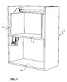
- Fig. 1 in räumlicher schematischer Darstellung ein Schrankeinbauteil mit Ablagefach im in den Oberschrank eingefahrenen oberen Position;
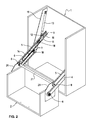
- Fig. 2 in vereinfachter räumlicher Darstellung das Schrankeinbauteil mit Ablagefach in der aus dem Oberschrank ausgefahrenen nach unten versetzten Position;
- Fig. 3 in räumlicher schematischer Darstellung den ausgefahrenen Schrankeinbauteil, bei welchem der Anlenkpunkt durch die Verschiebemittel verstellt wird;
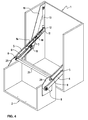
- Fig. 4 in räumlicher schematischer Darstellung den ausgefahrenen Schrankeinbauteil mit Ablagefach, bei welchem der Anlenkpunkt in die hintere Position verschoben ist;
- Fig. 5 in schematischer Darstellung eine Seitenansicht im Schnitt auf die Verschiebemittel, wobei sich der Anlenkpunkt in der vorderen Position befindet;
- Fig. 6 in schematischer Darstellung eine Seitenansicht im Schnitt auf die Verschiebemittel, wobei sich der Anlenkpunkt in der hintern Position befindet;
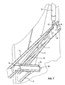
- Fig. 7 in räumlicher Darstellung eine vergrösserte Ansicht der Verschiebemittel.
- Figure 1 in a spatial schematic representation of a cabinet installation part with storage compartment in the upper cabinet retracted upper position.
- 2 in a simplified spatial representation of the cabinet installation part with storage compartment in the extended from the upper cabinet down position offset;
- 3 shows in a spatial schematic illustration the extended cabinet mounting part, in which the articulation point is adjusted by the displacement means;
- 4 shows in a spatial schematic representation of the extended cabinet insert with storage compartment, wherein the pivot point is moved to the rear position.
- Figure 5 is a schematic side view in section of the displacement means, wherein the articulation point is in the forward position.
- Figure 6 is a schematic representation of a side view in section of the displacement means, wherein the articulation point is in the rearward position.
- Fig. 7 in a three-dimensional view an enlarged view of the displacement means.
Aus Fig. 1 ist in schematischer Darstellung ein Oberschrank 1 ersichtlich, bei welchem aus Übersichtlichkeitsgründen die Türe, mit welcher der Oberschrank 1 verschlossen werden kann, sowie die obere Abdeckung weggelassen sind. In diesem Oberschrank 1 befindet sich der Schrankeinbauteil 2 mit einem Ablageflach 3. Selbstverständlich wäre es denkbar, hier noch weitere Ablagefächer anzubringen. Der Schrankeinbauteil 2 befindet sich in einer oberen, in den Oberschrank eingefahrenen Position, in welcher die Türen des Oberschrankes geschlossen werden könnten. Im unteren Teil des Oberschrankes 1 könnten neben dem Boden 4 ebenfalls noch weitere Ablagefächer für die Aufnahme von Utensilien eingesetzt werden.From Fig. 1 is a schematic representation of a wall unit 1 can be seen, in which for reasons of clarity, the door with which the upper cabinet 1 can be closed, and the upper cover are omitted. In this upper cabinet 1, the
Wie aus Fig. 2 ersichtlich ist, lässt sich der Schrankeinbauteil 2 bezüglich des Oberschrankes 1 in eine nach unten versetzte Position ausschwenken. Hierzu ist der Schrankeinbauteil 2 beidseitig durch zwei Schwenkhebel 5 und 6 gehalten. Jeder Schwenkhebel 5 und 6 ist jeweils über ein erstes Schwenklager 7 am Oberschrank 1 angelenkt. Jeder Schwenkhebel 5 und 6 ist jeweils über ein zweites Schwenklager 8 am Schrankeinbauteil 2 angelenkt. Die beiden Schwenkhebel 5 und 6 sind jeweils parallel ausgerichtet, die ersten Schwenklager 7 und die zweiten Schwenklager 8 bilden die Eckpunkte eines Parallelogramms, wodurch der Schrankeinbauteil 2 von der oberen in den Oberschrank eingefahrenen Position, wie dies in Fig. 1 dargestellt ist, parallel in die nach unten versetzte Position ausgeschwenkt werden kann, wie dies in Fig. 2 dargestellt ist.As can be seen from FIG. 2, the
Der jeweils obere Schwenkhebel 5 ist mit einer über das erste Schwenklager 7 hinausreichenden Verlängerung 9 versehen. In dieser Verlängerung 9 sind Führungen 10 angebracht, in welchen ein Schlitten 11 gleitbar gelagert ist und entlang dieser Führungen 10 verfahren werden kann.The respective
An diesen Schlitten 11 ist in einem Anlenkpunkt 12 das eine Ende eines Federelementes 13 in Form einer Gasdruckfeder angelenkt. Der andere Endbereich dieser Gasdruckfeder 13 ist am Oberschrank 1 gelenkig befestigt. Über Verschiebemittel 14, die später noch im Detail beschrieben werden, lässt sich nun der Schlitten 11 entlang der Führungen 10 in Längsrichtung des Schwenkhebels 5 verschieben. Dadurch lässt sich der Abstand des Anlenkpunktes 12, mit welchem die Gasdruckfeder 13 mit dem Schlitten 11 verbunden ist, zum ersten Schwenklager 7 verstellen. In der Position, wie sie in Fig. 2 dargestellt ist, befindet sich der Anlenkpunkt 12 in einer vorderen Position, dies heisst, dass der Abstand des Anlenkpunktes 12 zum ersten Schwenklager 7 am kleinsten ist. Dies bedeutet auch, dass in Folge der Hebelwirkung die Federkraft der Gasdruckfeder 13, mit welcher das Gewicht des beispielsweise mit Utensilien versehenen Schrankeinbauteils 2 kompensiert werden soll, am kleinsten ist. Diese Einstellung wird verwendet, wenn die Utensilien, die im Schrankeinbauteil 2 untergebracht sind, ein geringes Gewicht aufweisen.At this
In Fig. 3 ist der Verstellvorgang dargestellt, mit welchem der Abstand des Anlenkpunktes 12 zum ersten Schwenklager 7 vergrössert werden kann. Über die Verschiebemittel 14 wird der Schlitten 11 von der Position, wie sie in Fig. 2 dargestellt ist, entlang des Schwenkhebels 5 in eine hintere Position verschoben, der Abstand zwischen Anlenkpunkt 12 und erstem Schwenklager 7 wird hierbei vergrössert.In Fig. 3, the adjustment is shown, with which the distance of the
In Fig. 4 ist dargestellt, wenn der Schlitten und damit der Anlenkpunkt 12 sich in der hinteren Position befinden, das heisst in einer Position, wo der Abstand zwischen dem Anlenkpunkt 12 und dem ersten Schwenklager 7 am grössten ist. In diesem Zustand wirkt die grösste Kraft, mit welcher dem Gewicht des Schrankeinbauteils 2 und den sich darauf befindenden Utensilien entgegengewirkt wird. Diese Einstellung wird somit dann vorgenommen, wenn sich ein grosses Gewicht aufweisende Utensilien im Schrankeinbauteil 2 befinden.In Fig. 4 is shown when the carriage and thus the
Aus der Seitenansicht gemäss Fig. 5 ist ersichtlich, dass sich der Schlitten 11 in der vorderen Position befindet, der Abstand zwischen dem Anlenkpunkt 12 und dem ersten Schwenklager 7 ist am geringsten, so dass die auf das Schrankeinbauteil 2 durch die Gasdruckfeder 13 übertragene Kraft gering ist. Die hier dargestellte Position entspricht derjenigen, wie sie in Fig. 2 ersichtlich ist.From the side view of FIG. 5 it can be seen that the
In der Seitenansicht gemäss Fig. 6 befindet sich der Schlitten 11 in der hinteren Position, dies bedeutet, dass der Anlenkpunkt 12 vom ersten Schwenklager 7 einen grossen Abstand hat. Dadurch wird erreicht, dass die auf das Schrankeinbauteil 2 wirkende Kraft am grössten ist, das Gewicht der Utensilien, die im Schrankeinbauteil 2 untergebracht sind, kann gross sein, dieses wird durch die Gasdruckfeder im Wesentlichen kompensiert. Diese hier dargestellte Lage entspricht derjenigen, wie sie in Fig. 4 dargestellt ist.In the side view according to FIG. 6, the
Zum Verstellen beziehungsweise zum Verschieben des Schlittens 11 von einer Position in die andere wird der Schrankeinbauteil 2 vorteilhafterweise auf eine Höhe gebracht, dass der Hebel 5 im Wesentlichen senkrecht zu der Gasdruckfeder 13 steht. In dieser Position, welche durch die Bedienerperson durch Halten des Schrankeinbauteils 2 erreicht wird, kann eine Verschiebung des Schlittens 11 vorgenommen werden, ohne dass eine wesentliche Federkraft der Gasdruckfeder 13 überwunden werden muss.For adjusting or for displacing the
Aus Fig. 7 ist der Schlitten 11 ersichtlich, welcher entlang der Führungen 10, die im Schwenkhebel 5 angebracht sind, verschiebbar ist. An diesem Schlitten angebracht ist der Anlenkpunkt 12, mit welchem die Gasdruckfeder 13 mit dem Schlitten 11 gelenkig verbunden ist. Die Verschiebemittel 14 für den Schlitten 11 umfassen einen Umlenkhebel 15, welcher schwenkbar in einem Lagerbock 16 gehalten ist, welcher am Schwenkhebel 5 befestigt ist. Am Umlenkhebel 15 angelenkt sind zwei Lenkhebel 17. Diese beiden Lenkhebel 17 sind mit dem Schlitten 11 gelenkig verbunden. Durch das Umlenken des Umlenkhebels 15 von einer vorderen Position, dargestellt in den Fig. 2 und 5, in eine hintere Position, dargestellt in den Fig. 4 und 6, wird das Verschieben des Schlittens 11 von einer vorderen Position (Fig. 2 und Fig. 5) in eine hintere Position (Fig. 4 und Fig. 6) erhalten. Der Umlenkhebel 15 kann in den beiden Positionen beispielsweise reibschlüssig im Hebel 5, der U-förmig ausgebildet ist, gehalten werden, wodurch ein selbständiges Verstellen verhindert wird. Für die bessere Bedienbarkeit kann der Umlenkhebel 15 noch mit einem Handgriff 18 versehen sein.From Fig. 7, the
Wie beispielsweise den Fig. 2 bis 4 entnommen werden kann, weisen die ersten Schwenklager 7 jeweils einen Lagerzapfen 18 auf, welche an einem weiteren plattenförmigen Element 19 befestigt sind, auf welche das an den Schwenkhebeln 5 und 6 befestigte Lagerelement aufsetzbar ist. Dieses weitere plattenförmige Element 19 ist am Oberschrank 1 befestigt, beispielsweise durch Verschraubung. An diesem weiteren plattenförmigen Element 19 ist auch die Halterung für die Gasdruckfeder 13 angebracht.As can be seen for example in FIGS. 2 to 4, the
In gleicher Weise sind die Lagerzapfen der zweiten Schwenklager 8 an einem plattenförmigen Element 20 befestigt, auf welche das an den zweiten Schwenkhebeln 5 und 6 befestigte Lagerelement aufsetzbar ist. Dieses plattenförmige Element 20 ist beispielsweise ebenfalls durch Verschraubung am Schrankeinbauteil 2 befestigt. Durch diese Anordnung kann der ganze Mechanismus zum Verschwenken des Schrankeinbauteils 2 fertig vormontiert werden, die so gebildeten Baugruppen können dann in relativ einfacher Weise und mit geringem Aufwand vor Ort in einen bestehenden Oberschrank 1 eingebaut werden.In the same way, the bearing journals of the second pivot bearing 8 are fastened to a plate-shaped
Im hier dargestellten Ausführungsbeispiel sind auf beiden Seiten des Schrankeinbauteils 2 Gasdruckfedern 13 eingesetzt. Üblicherweise werden die Schlitten 11, an welche diese Gasdruckfedern 13 angelenkt sind, beim Einstellen in die jeweils gleiche Position gebracht. Dadurch erhält man zwei Einstellungen, die eine für ein geringes Gewicht, die andere für ein grösseres Gewicht. Es ist aber auch denkbar, dass man den einen Schlitten 11 in der vorderen Position belässt, während der gegenüberliegende Schlitten 11 in die hintere Position eingestellt wird. Dadurch erhält man eine Kraft der Gasdruckfedern, die für ein mittleres Gewicht des Schrankeinbauteils 2 mit den darin enthalten Utensilien geeignet ist. Dies bedingt, dass die Lagerung des Schrankeinbauteils relativ stabil ist, so dass kein Verkanten entsteht, hierzu kann beispielsweise in den beiden zweiten Schwenklagern 8 für die oberen Schwenkhebel 5 eine Verbindungsstange 21 zur Stabilisierung eingesetzt werden, wie dies in den Fig. 2 bis 4 ersichtlich ist.In the embodiment shown here 2 gas pressure springs 13 are used on both sides of the cabinet insert part. Usually, the
Mit dieser erfindungsgemässen Anordnung kann ein Schrankeinbauteil für einen Oberschrank von einer oberen in den Oberschrank eingefahrenen Position in eine aus dem Oberschrank ausgefahrene und nach unten versetzte Position gebracht werden, wobei die dem Gewicht entgegenwirkende Federkraft eingestellt werden kann, was die Bedienung vereinfacht und für die Bedienerperson angenehmer macht.With this arrangement according to the invention, a cabinet installation part for a wall unit can be moved from an upper retracted into the upper cabinet position in a displaced from the upper cabinet and down offset position, the weight counteracting spring force can be adjusted, which simplifies the operation and for the operator makes it more pleasant.
Claims (9)
Priority Applications (2)
| Application Number | Priority Date | Filing Date | Title |
|---|---|---|---|
| DE200650001737 DE502006001737D1 (en) | 2006-02-16 | 2006-02-16 | Cabinet installation part with storage compartment |
| EP20060110065 EP1820420B1 (en) | 2006-02-16 | 2006-02-16 | Built-in cupboard elements for storage |
Applications Claiming Priority (1)
| Application Number | Priority Date | Filing Date | Title |
|---|---|---|---|
| EP20060110065 EP1820420B1 (en) | 2006-02-16 | 2006-02-16 | Built-in cupboard elements for storage |
Publications (2)
| Publication Number | Publication Date |
|---|---|
| EP1820420A1 true EP1820420A1 (en) | 2007-08-22 |
| EP1820420B1 EP1820420B1 (en) | 2008-10-08 |
Family
ID=36128542
Family Applications (1)
| Application Number | Title | Priority Date | Filing Date |
|---|---|---|---|
| EP20060110065 Expired - Fee Related EP1820420B1 (en) | 2006-02-16 | 2006-02-16 | Built-in cupboard elements for storage |
Country Status (2)
| Country | Link |
|---|---|
| EP (1) | EP1820420B1 (en) |
| DE (1) | DE502006001737D1 (en) |
Cited By (10)
| Publication number | Priority date | Publication date | Assignee | Title |
|---|---|---|---|---|
| CN103976571A (en) * | 2014-05-29 | 2014-08-13 | 于维恕 | Storage frame sleeve centering clutch stressing mechanism |
| DE102013018498A1 (en) * | 2013-11-06 | 2015-05-07 | Kesseböhmer Holding e.K. | Pivoting tray for a piece of furniture |
| WO2017129733A1 (en) | 2016-01-29 | 2017-08-03 | Poussuet Pascal | System for optimizing the accessibility of a storage compartment |
| US9737139B1 (en) * | 2010-11-23 | 2017-08-22 | Drawers In Motion, LLC | Rack and drawer systems |
| AT518545A4 (en) * | 2016-10-17 | 2017-11-15 | Blum Gmbh Julius | furniture drive |
| US10376057B2 (en) | 2010-11-23 | 2019-08-13 | Drawers In Motion, LLC | Rack and drawer systems |
| EP3738466A1 (en) | 2019-05-16 | 2020-11-18 | Vauth-Sagel Holding GmbH & Co. KG | Pivoting bracket for mounting a swinging component and cabinet with such a pivoting bracket |
| CN112716157A (en) * | 2020-12-23 | 2021-04-30 | 杭州电子科技大学 | Foldable lifting kitchen hanging cabinet and using method thereof |
| US11723457B2 (en) | 2017-01-27 | 2023-08-15 | 143046 Canada Inc. | Overhead storage unit |
| US11864648B2 (en) | 2019-10-04 | 2024-01-09 | 143046 Canada Inc. | Overhead storage unit with pivoting storage containers |
Families Citing this family (1)
| Publication number | Priority date | Publication date | Assignee | Title |
|---|---|---|---|---|
| US11684155B2 (en) | 2017-01-27 | 2023-06-27 | 143046 Canada Inc. | Pivotable overhead storage unit |
Citations (2)
| Publication number | Priority date | Publication date | Assignee | Title |
|---|---|---|---|---|
| DE20100823U1 (en) * | 2001-01-17 | 2001-11-15 | Mauser Office Gmbh | furniture |
| DE10340749A1 (en) * | 2003-08-27 | 2005-06-09 | GfP (Gesellschaft für Produktivitätsplanung und Produktentwicklung) mbH | Wall unit for kitchens or laboratories comprises cupboard which can swivel forwards and downwards and is mounted on pairs of parallel levers whose upper ends are attached by pivots to wall or upper carcass, into which cupboard fits |
-
2006
- 2006-02-16 EP EP20060110065 patent/EP1820420B1/en not_active Expired - Fee Related
- 2006-02-16 DE DE200650001737 patent/DE502006001737D1/en active Active
Patent Citations (2)
| Publication number | Priority date | Publication date | Assignee | Title |
|---|---|---|---|---|
| DE20100823U1 (en) * | 2001-01-17 | 2001-11-15 | Mauser Office Gmbh | furniture |
| DE10340749A1 (en) * | 2003-08-27 | 2005-06-09 | GfP (Gesellschaft für Produktivitätsplanung und Produktentwicklung) mbH | Wall unit for kitchens or laboratories comprises cupboard which can swivel forwards and downwards and is mounted on pairs of parallel levers whose upper ends are attached by pivots to wall or upper carcass, into which cupboard fits |
Cited By (19)
| Publication number | Priority date | Publication date | Assignee | Title |
|---|---|---|---|---|
| US9737139B1 (en) * | 2010-11-23 | 2017-08-22 | Drawers In Motion, LLC | Rack and drawer systems |
| US10376057B2 (en) | 2010-11-23 | 2019-08-13 | Drawers In Motion, LLC | Rack and drawer systems |
| CN104706043A (en) * | 2013-11-06 | 2015-06-17 | 克塞伯默尔控股公司 | Pull-down shelf for furniture |
| US9055813B2 (en) | 2013-11-06 | 2015-06-16 | Kesseböhmer Holding e.K. | Pull-down shelf for furniture |
| DE102013018498B4 (en) * | 2013-11-06 | 2016-01-07 | Kesseböhmer Holding e.K. | Pivoting tray for a piece of furniture |
| EP2870895A1 (en) * | 2013-11-06 | 2015-05-13 | Kesseböhmer Holding e.K. | Pivoting shelf for a piece of furniture |
| DE102013018498A1 (en) * | 2013-11-06 | 2015-05-07 | Kesseböhmer Holding e.K. | Pivoting tray for a piece of furniture |
| CN103976571A (en) * | 2014-05-29 | 2014-08-13 | 于维恕 | Storage frame sleeve centering clutch stressing mechanism |
| CN103976571B (en) * | 2014-05-29 | 2017-04-19 | 于维恕 | Storage frame sleeve centering clutch stressing mechanism |
| WO2017129733A1 (en) | 2016-01-29 | 2017-08-03 | Poussuet Pascal | System for optimizing the accessibility of a storage compartment |
| WO2018071930A1 (en) * | 2016-10-17 | 2018-04-26 | Julius Blum Gmbh | Furniture drive |
| AT518545B1 (en) * | 2016-10-17 | 2017-11-15 | Blum Gmbh Julius | furniture drive |
| CN109843118A (en) * | 2016-10-17 | 2019-06-04 | 优利思百隆有限公司 | Furniture drive |
| AT518545A4 (en) * | 2016-10-17 | 2017-11-15 | Blum Gmbh Julius | furniture drive |
| JP2019534760A (en) * | 2016-10-17 | 2019-12-05 | ユリウス ブルーム ゲー・エム・ベー・ハーJulius Blum GmbH | Furniture drive |
| US11723457B2 (en) | 2017-01-27 | 2023-08-15 | 143046 Canada Inc. | Overhead storage unit |
| EP3738466A1 (en) | 2019-05-16 | 2020-11-18 | Vauth-Sagel Holding GmbH & Co. KG | Pivoting bracket for mounting a swinging component and cabinet with such a pivoting bracket |
| US11864648B2 (en) | 2019-10-04 | 2024-01-09 | 143046 Canada Inc. | Overhead storage unit with pivoting storage containers |
| CN112716157A (en) * | 2020-12-23 | 2021-04-30 | 杭州电子科技大学 | Foldable lifting kitchen hanging cabinet and using method thereof |
Also Published As
| Publication number | Publication date |
|---|---|
| DE502006001737D1 (en) | 2008-11-20 |
| EP1820420B1 (en) | 2008-10-08 |
Similar Documents
| Publication | Publication Date | Title |
|---|---|---|
| EP1820420B1 (en) | Built-in cupboard elements for storage | |
| DE19603911C2 (en) | Folding backrest for vehicle seats, in particular motor vehicle seats | |
| DE19510618A1 (en) | Vehicle seat, which can be moved longitudinally if backrest is folded | |
| EP3181396A1 (en) | Vehicle vibration device | |
| EP0184620A2 (en) | Storing device in the linings of motor vehicles | |
| DE19902467B4 (en) | Armchair with stand-up aid | |
| DE202010017933U1 (en) | Fitting for corner cabinets | |
| DE102005055138B4 (en) | Two-sided opening container | |
| DE19717782C2 (en) | Seat device in a combat vehicle, in particular an observation or spy vehicle | |
| WO2018077822A1 (en) | Headrest arrangement comprising a first and a second pivotable lifting element for adjusting a headrest body | |
| EP0230257A2 (en) | Steering column supporting a steering wheel and at least one control lever | |
| DE102004019785A1 (en) | Flap fitting e.g. for furniture flap, positioned between safe in cabinet body locking vertical closing position and open position upward adjustable with setting lever and in operation position axle | |
| EP2064971A1 (en) | Fitting for a corner cupboard | |
| DE102007013081B4 (en) | Armrest, in particular for motor vehicles | |
| DE102009037162A1 (en) | Seat furniture item | |
| DE10333912B4 (en) | Table unit for vehicle seats | |
| DE102007013080A1 (en) | Arm rest for vehicle, has actuating element formed by individually movable handle, which is adjustable in two switching positions, where each switching position of handle is assigned to position of locking device | |
| DE102015121765A1 (en) | Vehicle vibration device | |
| EP2191745B1 (en) | Fitting for a corner cupboard | |
| DE10318718A1 (en) | Adjustable motor vehicle seat, esp. for third and fourth seat rows has adjusting mechanism with locks to permit seat sliding, backrest tilting, and seat tipping movements | |
| DE102012004149B4 (en) | Longitudinally adjustable vehicle seat | |
| AT523271A4 (en) | Guide arrangement for guiding at least one movable furniture part | |
| DE7620918U1 (en) | LIFTING AND LOWERING SUPPORT | |
| DE3935108A1 (en) | Folding pushchair for child - incorporates locking catch for both erected setting and collapsed setting | |
| DE102012112524B4 (en) | commercial vehicle seat |
Legal Events
| Date | Code | Title | Description |
|---|---|---|---|
| PUAI | Public reference made under article 153(3) epc to a published international application that has entered the european phase |
Free format text: ORIGINAL CODE: 0009012 |
|
| AK | Designated contracting states |
Kind code of ref document: A1 Designated state(s): AT BE BG CH CY CZ DE DK EE ES FI FR GB GR HU IE IS IT LI LT LU LV MC NL PL PT RO SE SI SK TR |
|
| AX | Request for extension of the european patent |
Extension state: AL BA HR MK YU |
|
| 17P | Request for examination filed |
Effective date: 20071215 |
|
| GRAP | Despatch of communication of intention to grant a patent |
Free format text: ORIGINAL CODE: EPIDOSNIGR1 |
|
| AKX | Designation fees paid |
Designated state(s): DE IT |
|
| GRAS | Grant fee paid |
Free format text: ORIGINAL CODE: EPIDOSNIGR3 |
|
| GRAA | (expected) grant |
Free format text: ORIGINAL CODE: 0009210 |
|
| AK | Designated contracting states |
Kind code of ref document: B1 Designated state(s): DE IT |
|
| REF | Corresponds to: |
Ref document number: 502006001737 Country of ref document: DE Date of ref document: 20081120 Kind code of ref document: P |
|
| PLBE | No opposition filed within time limit |
Free format text: ORIGINAL CODE: 0009261 |
|
| STAA | Information on the status of an ep patent application or granted ep patent |
Free format text: STATUS: NO OPPOSITION FILED WITHIN TIME LIMIT |
|
| 26N | No opposition filed |
Effective date: 20090709 |
|
| PGFP | Annual fee paid to national office [announced via postgrant information from national office to epo] |
Ref country code: DE Payment date: 20110218 Year of fee payment: 6 Ref country code: IT Payment date: 20110225 Year of fee payment: 6 |
|
| PG25 | Lapsed in a contracting state [announced via postgrant information from national office to epo] |
Ref country code: IT Free format text: LAPSE BECAUSE OF NON-PAYMENT OF DUE FEES Effective date: 20120216 |
|
| REG | Reference to a national code |
Ref country code: DE Ref legal event code: R119 Ref document number: 502006001737 Country of ref document: DE Effective date: 20120901 |
|
| PG25 | Lapsed in a contracting state [announced via postgrant information from national office to epo] |
Ref country code: DE Free format text: LAPSE BECAUSE OF NON-PAYMENT OF DUE FEES Effective date: 20120901 |