EP1819927B1 - Hermetic compressor - Google Patents
Hermetic compressor Download PDFInfo
- Publication number
- EP1819927B1 EP1819927B1 EP05814395.9A EP05814395A EP1819927B1 EP 1819927 B1 EP1819927 B1 EP 1819927B1 EP 05814395 A EP05814395 A EP 05814395A EP 1819927 B1 EP1819927 B1 EP 1819927B1
- Authority
- EP
- European Patent Office
- Prior art keywords
- sound deadening
- deadening space
- oil
- muffler
- face
- Prior art date
- Legal status (The legal status is an assumption and is not a legal conclusion. Google has not performed a legal analysis and makes no representation as to the accuracy of the status listed.)
- Ceased
Links
- 239000003507 refrigerant Substances 0.000 claims description 48
- 239000003921 oil Substances 0.000 description 95
- XEEYBQQBJWHFJM-UHFFFAOYSA-N Iron Chemical group [Fe] XEEYBQQBJWHFJM-UHFFFAOYSA-N 0.000 description 14
- 230000008878 coupling Effects 0.000 description 8
- 238000010168 coupling process Methods 0.000 description 8
- 238000005859 coupling reaction Methods 0.000 description 8
- 230000007423 decrease Effects 0.000 description 7
- 239000007788 liquid Substances 0.000 description 6
- 238000007906 compression Methods 0.000 description 5
- 229910000831 Steel Inorganic materials 0.000 description 4
- 230000006835 compression Effects 0.000 description 4
- 230000007246 mechanism Effects 0.000 description 4
- 239000010959 steel Substances 0.000 description 4
- WSQZNZLOZXSBHA-UHFFFAOYSA-N 3,8-dioxabicyclo[8.2.2]tetradeca-1(12),10,13-triene-2,9-dione Chemical compound O=C1OCCCCOC(=O)C2=CC=C1C=C2 WSQZNZLOZXSBHA-UHFFFAOYSA-N 0.000 description 3
- 229910052742 iron Inorganic materials 0.000 description 3
- 238000000034 method Methods 0.000 description 3
- 230000008569 process Effects 0.000 description 3
- 229920005989 resin Polymers 0.000 description 3
- 239000011347 resin Substances 0.000 description 3
- 230000005484 gravity Effects 0.000 description 2
- 238000005461 lubrication Methods 0.000 description 2
- 239000000463 material Substances 0.000 description 2
- 229910052761 rare earth metal Inorganic materials 0.000 description 2
- 150000002910 rare earth metals Chemical class 0.000 description 2
- 239000000725 suspension Substances 0.000 description 2
- 238000004804 winding Methods 0.000 description 2
- 239000004215 Carbon black (E152) Substances 0.000 description 1
- 229910000976 Electrical steel Inorganic materials 0.000 description 1
- 229910052779 Neodymium Inorganic materials 0.000 description 1
- 230000002159 abnormal effect Effects 0.000 description 1
- 238000013459 approach Methods 0.000 description 1
- 230000008901 benefit Effects 0.000 description 1
- 238000001816 cooling Methods 0.000 description 1
- 229920006038 crystalline resin Polymers 0.000 description 1
- 230000001351 cycling effect Effects 0.000 description 1
- 230000001419 dependent effect Effects 0.000 description 1
- 239000006185 dispersion Substances 0.000 description 1
- 230000007613 environmental effect Effects 0.000 description 1
- 239000003365 glass fiber Substances 0.000 description 1
- 238000010438 heat treatment Methods 0.000 description 1
- 229930195733 hydrocarbon Natural products 0.000 description 1
- 150000002430 hydrocarbons Chemical class 0.000 description 1
- 230000006698 induction Effects 0.000 description 1
- 239000011810 insulating material Substances 0.000 description 1
- WABPQHHGFIMREM-UHFFFAOYSA-N lead(0) Chemical compound [Pb] WABPQHHGFIMREM-UHFFFAOYSA-N 0.000 description 1
- 229910052751 metal Inorganic materials 0.000 description 1
- 239000002184 metal Substances 0.000 description 1
- QEFYFXOXNSNQGX-UHFFFAOYSA-N neodymium atom Chemical compound [Nd] QEFYFXOXNSNQGX-UHFFFAOYSA-N 0.000 description 1
- 230000000717 retained effect Effects 0.000 description 1
- 229920003002 synthetic resin Polymers 0.000 description 1
- 239000000057 synthetic resin Substances 0.000 description 1
- 238000010792 warming Methods 0.000 description 1
Images





Classifications
-
- F—MECHANICAL ENGINEERING; LIGHTING; HEATING; WEAPONS; BLASTING
- F04—POSITIVE - DISPLACEMENT MACHINES FOR LIQUIDS; PUMPS FOR LIQUIDS OR ELASTIC FLUIDS
- F04B—POSITIVE-DISPLACEMENT MACHINES FOR LIQUIDS; PUMPS
- F04B39/00—Component parts, details, or accessories, of pumps or pumping systems specially adapted for elastic fluids, not otherwise provided for in, or of interest apart from, groups F04B25/00 - F04B37/00
- F04B39/0027—Pulsation and noise damping means
- F04B39/0055—Pulsation and noise damping means with a special shape of fluid passage, e.g. bends, throttles, diameter changes, pipes
- F04B39/0061—Pulsation and noise damping means with a special shape of fluid passage, e.g. bends, throttles, diameter changes, pipes using muffler volumes
-
- Y—GENERAL TAGGING OF NEW TECHNOLOGICAL DEVELOPMENTS; GENERAL TAGGING OF CROSS-SECTIONAL TECHNOLOGIES SPANNING OVER SEVERAL SECTIONS OF THE IPC; TECHNICAL SUBJECTS COVERED BY FORMER USPC CROSS-REFERENCE ART COLLECTIONS [XRACs] AND DIGESTS
- Y10—TECHNICAL SUBJECTS COVERED BY FORMER USPC
- Y10S—TECHNICAL SUBJECTS COVERED BY FORMER USPC CROSS-REFERENCE ART COLLECTIONS [XRACs] AND DIGESTS
- Y10S181/00—Acoustics
- Y10S181/403—Refrigerator compresssor muffler
Definitions
- the present invention relates to a hermetic compressor used in a refrigerating cycle of an electric refrigerator for household and professional uses, and the like.
- hermetic compressor utilized in the refrigerator, the refrigerating cycle apparatus and the like, there is used a resin-made suction muffler.
- These conventional hermetic compressors are disclosed in, for example, Japanese Patent Unexamined Publication No. H05-195953 and the like.
- Fig. 9 shows a longitudinal sectional view of the conventional hermetic compressor.
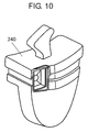
- Fig. 10 shows a perspective view of a suction muffler used in the conventional hermetic compressor.
- oil 202 is stored in a bottom part of hermetic container 201 (hereafter referred to as "container 201").
- Compressing member 204 (hereafter referred to as “member 204") is supported elastically with respect to container 201 by suspension spring 206.
- Member 204 is constituted by motor element 210, and compressing element 220 disposed above motor element 210.
- Motor element 210 is constituted by stator 212 and rotor 214.
- Compressing element 220 has crank shaft 221 (hereafter referred to as "shaft 221").
- Shaft 221 is constituted by main shaft 222 and eccentric shaft 224.
- Main shaft 222 is supported rotatably with respect to bearing 227 provided in block 226.
- Rotor 214 is fixed to main shaft 222.
- shaft 221 has oil supplying mechanism 225.
- piston 228 is inserted so as to be capable of reciprocating with respect to cylinder 230 monolithically formed in block 226.
- Cylinder 230 forms, together with valve plate 232 (hereafter referred to as "plate 232"), compressing chamber 234.
- a piston pin (not shown in the drawing) attached to piston 228 is inserted rotatably with respect to coupling part 236 that is coupling means.
- Eccentric shaft 224 is inserted rotatably with respect to coupling part 236.
- Cylinder head 238 lids plate 232.
- Suction muffler 240 (hereafter referred to as “muffler 240”) is retained by cylinder head 238 and plate 232 while being nipped. Muffler 240 is molded and formed by a resin such as poly-butylene terephthalate. Inside muffler 240, there is provided sound deadening space 242 whose inside face has been formed approximately like a circular cone. In a lower end of muffler 240, there is provided oil discharged opening 246 (hereafter referred to as “opening 246"). By doing like this, hermetic compressor 200 (hereafter referred to as “compressor 200”) is constituted.
- stator 212 When an electric current is applied to motor element 210, stator 212 generates a rotating magnetic field. By this rotating magnetic field, rotor 214 rotates together with main shaft 222. By the rotation of main shaft 222, eccentric shaft 224 eccentrically moves. An eccentric motion of eccentric shaft 224 is transmitted to piston 228 through coupling part 236. As a result, piston 228 reciprocates in cylinder 230.
- a refrigerant gas (not shown in the drawing) having returned from a refrigerating cycle (not shown in the drawing) outside container 201 is introduced into compressing chamber 234 through muffler 240. The refrigerant gas introduced into compressing chamber 234 is compressed in compressing chamber 234 by piston 228. The compressed refrigerant gas is sent again to the refrigerating cycle outside container 201.
- Muffler 240 bears a function of reducing the generated noise. Additionally, by the fact that muffler 240 is formed by the resin whose heat transfer is small, a heating of the refrigerant gas is prevented. By this fact, a decrease in performance of compressor 200 is prevented.
- oil supplying mechanism 225 supplies oil 202 stored in the bottom part of container 201 to upper compressing element 220.
- Oil 202 supplied to compressing element 220 lubricates some sliding portions of bearing 227 and the like. Thereafter, oil 202 is dispersed from an upper end of shaft 221 to the environment by the centrifugal force of main shaft 222. Dispersed oil 202 lubricates constitutional members such as piston 228 and cylinder 230. Additionally, oil 202 adheres to inside wall surface 250 of container 201, and flows down to the bottom part of container 201 along inside wall surface 250.
- oil 202 having dispersed from the upper end of shaft 221 is sucked also into muffler 240 with a flow of the refrigerant gas.
- the flow of the refrigerant gas is released into sound deadening space 242 in muffler 240, and its velocity decreases.
- Oil 202 having dropped into sound deadening space 242 flows down along inside wall surface 252 of sound deadening space 242.
- Oil 202 having flowed down collects to a lower end of sound deadening space 242. Thereafter, oil 202 having collected to the lower end of sound deadening space 242 is discharged from opening 246 to the outside of muffler 240.
- sound deadening space 242 necessitates a spatial volume (width or depth of sound deadening space 242) larger than a certain value.
- sound deadening space 242 is the shape like the circular cone having an angle of certain degree. Thereupon, for muffler 240, a height of certain degree becomes necessary, so that opening 246 approaches a liquid level of oil 202 stored in the bottom part of container 201.
- the liquid level of oil 202 stored in the bottom part of container 201 changes by an operating state of compressor 200. Especially, at a starting time of compressor 200, a refrigerant gas having dissolved in oil 202 bubbles out by a pressure drop in container 201. For this reason, the liquid level of oil 202 ascends, so that opening 246 is immersed in oil 202. Additionally, an average pressure in sound deadening space 242 is low in comparison with that in container 201. As a result, a large quantity of oil 202 enters from opening 246 to sound deadening space 242, so that oil 202 is liable to remain in muffler 240.
- opening 246 while being separated from oil 202 in the bottom part of container 201 by reducing an incline of inner wall surface 252 to thereby suppress a height of muffler 240 to a low level.
- a dropping velocity of oil 202 flowing down along inner wall surface 252 becomes slow, so the oil 202 is not discharged sufficiently from sound deadening space 242.
- oil 202 is liable to remain in muffler 240.
- a hermetic compressor comprising a suction muffler having an inlet pipe and an outlet pipe arranged in a sound deadening space of the suction muffler.
- Said inlet pipe and said outlet pipe are tubular and extend parallel to each other.
- Said pipes are disposed such, that an opening of said inlet pipe and of said outlet pipe are opposed to a cover covering the sound deadening space.
- Said outlet pipe is placed substantially at a center portion of said sound deadening space, whereas said inlet pipe is disposed at a side of the sound deadening space.
- the sound deadening space has substantially a similar thickness in these regions.
- the opening of the inlet pipe and the outlet pipe are provided in an upper part of the sound deadening space to provide sufficient space below them for collecting oil flowing into the sound deadening space through the inlet pipe with the gas while a compression process of the hermetic compressor is performed.
- JP 2004-293464 relates to a hermetic compressor comprising a suction muffler having a sound deadening space, wherein an inlet pipe is provided in said sound deadening space. Furthermore, said suction muffler has an outlet pipe provided below the suction muffler and comprises a seat and a flange to which a cylinder head with a resonance chamber and a discharged chamber is adapted to. In operation, the sound deadening space contains a gas which is sucked through the outlet pipe to a compression chamber of the hermetic compressor via said resonance chamber and said discharge chamber.
- US 2004/179955 A1 discloses a suction muffler having a gas inlet and a gas outlet communicating with the gas inlet via a gas flowing space.
- Said gas inlet is connected to a suction pipe extending outward of a hermetic compressor to guide a refrigerant gas from an outside into a compressing chamber.
- Adjacent to said gas flowing space is provided a sound deadening space separated from said gas flowing space by a wall having an opening for connecting said gas flowing space with said sound deadening space. Through said opening, a small amount of refrigerant gas flows into said sound deadening space in operation of the suction muffler.
- JP 2000-130147 refers particularly to a suction muffler comprising a gas inlet pipe and a gas outlet pipe, wherein an opening of the inlet pipe and an opening of the outlet pipe are provided in a sound deadening space such, that the opening of the outlet pipe faces said opening of said inlet pipe with a small distance therebetween.
- US 6 206 135 B1 relates to a suction muffler for a hermetic compressor, wherein said suction muffler has two sound deadening spaces each having an opening communicating with a gas flow passage separating said two sound deadening spaces from each other.
- Said gas flow passage is connected at one end with a gas inlet and at the other end to a gas outlet. Near to said gas inlet and said gas outlet is provided an oil discharge opening connecting the sound deadening spaces with the gas inlet and the gas outlet, respectively.
- JP 2002-349436 discloses a suction muffler comprising an inlet pipe and an outlet pipe having an L-shaped form, wherein an opening of said outlet pipe in a sound deadening space of said suction muffler is opposed to an opening of said outlet pipe with a small distance there between.
- a hermetic compressor having the features as defined in claim 1.
- the hermetic compressor in which the oil is more difficult to remain in the suction muffler, whose noise is lower, and whose performance is stabilized. Further preferred embodiments of hermetic compressors are defined in the dependent claims.
- Fig. 1 is a longitudinal sectional view of a hermetic compressor in an embodiment of the present invention.
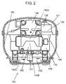
- Fig. 2 is a sectional view at a 2 - 2 line of the hermetic compressor shown in Fig. 1 .
- Fig. 3 is a sectional view of a suction muffler used in the hermetic compressor shown in Fig. 1 .
- Fig. 4 is a perspective view of the suction muffler shown in Fig. 3 .
- oil 102 is stored in a bottom part inside hermetic container 101 (hereafter referred to as "container 101"). Additionally, there is accommodated compressing member 104 (hereafter referred to as “member 104") inside container 101. Member 104 is constituted by motor element 110 and compressing element 120 driven by motor element 110. Member 104 is supported elastically with respect to container 101 by suspension spring 106. Further, inside container 101, there is filled a hydrocarbon refrigerant gas, such as R600a for instance, whose global warming potential is low. Further, power source terminal 108 for supplying a power source to motor element 110 is attached to container 101. By doing like this, hermetic compressor 100 (hereafter referred to as "compressor 100”) is constituted.
- compressor 100 hermetic compressor 100
- Motor element 110 forms a salient pole concentrated winding-typed DC brushless motor.
- Motor element 110 has stator 112 and rotor 114.
- Motor element 110 is connected to an inverter drive circuit (not shown in the drawing) by lead wire 109 through power source terminal 108.
- Stator 112 is formed with a winding being wound around magnetic pole teeth of an iron core of stator 112 through an insulating material.
- the iron core of stator 112 is formed by a so-called flat-rolled electromagnetic steel sheets and strip (silicon steel plate), such as non-oriented magnetic sheets and strip (JIS C2552) for instance, whose iron loss is little.
- JIS C2552 non-oriented magnetic sheets and strip
- the iron core of stator 112 it is desirable to use the flat-rolled magnetic steel sheets and strip whose thickness is 0.35 mm, and whose iron loss is as very little as 0.4 W/kg or less.
- Rotor 114 is disposed inside stator 112.
- Rotor 114 is constituted by an iron core of rotor 114, and a permanent magnet disposed inside the iron core of rotor 114.
- the permanent magnet there is used rare earth such as neodymium for instance.
- rotor 114 is fixed to main shaft 122 constituting crank shaft 121 (hereafter referred to as "shaft 121").
- the iron core of rotor 114 is also formed with the flat-rolled electromagnetic steel sheets and strip, such as non-oriented electromagnetic sheets and strip (JIS C2552), being laminated.
- motor element 110 is operated in various frequencies between 15 r/sec (revolutions per second) and 75 r/sec by an inverter drive.
- Compressing element 120 is disposed above motor element 110.
- Shaft 121 constituting compressing element 120 has main shaft 122 and eccentric shaft 124. A lower end part of main shaft 122 is immersed in oil 102 stored in the bottom part of container 101.
- oil supplying mechanism 125 which communicates from the lower end part of main shaft 122 to an upper end part of eccentric shaft 124 and which is for supplying oil 102 to an upper part of compressing element 120.
- bearing 127 and cylinder 130 there are provided bearing 127 and cylinder 130. Bearing 127 rotatably supports main shaft 122.
- Piston 128 is fitted to and inserted into cylinder 130 under a state capable of reciprocating.
- Valve plate 132 (hereafter referred to as "plate 132") is disposed in an end face cylinder 130.
- Compressing chamber 134 is formed by cylinder 130 and plate 132.
- Piston 128 and eccentric shaft 124 are connected by coupling part 136 that is coupling means.
- Muffler 140 Suction muffler 140 (hereafter referred to as "muffler 140") is fixed by the fact that it is supported while being nipped by plate 132 and cylinder head 138.
- Muffler 140 is formed by a synthetic resin, such as poly-butylene terephthalate, that is a crystalline resin to which glass fibers have been mainly added.
- sound deadening space 142 is formed inside muffler 140.
- Muffler 140 has inlet pipe 150 and outlet pipe 152.
- Inlet pipe 150 opens in its one end to sound deadening space 142, and opens in its other end into container 101.
- Outlet pipe 152 opens in its one end to sound deadening space 142, and opens in its other end to compressing chamber 134.
- a back face side of muffler 140 adjoins stator 112 and block 126.
- Muffler 140 has an external shape extending along stator 112 and block 126.
- lower portion 140B in a front face side of muffler 140 is thinner in its thickness than upper portion 140A in order to secure a distance from power source terminal 108.
- Lower portion 140B is a shape whose thickness is thin in its center part in comparison with its left and right.
- lower surface 140C of muffler 140 is formed by a substantially horizontal face. Lower surface 140C has a certain distance from oil 102 stored in the bottom part of container 101.
- outlet pipe 152 extends in an approximately horizontal direction along a wall surface in an upper end of sound deadening space 142.
- a tip of outlet pipe 152 opens in the vicinity of the wall surface in the upper end of sound deadening space 142.
- the refrigerant gas flows out along gas flows 152A, 152B which are indicated by arrows of alternate long and short dash lines while passing through outlet pipe 152 from sound deadening space 142.
- annular gas flow 143 is generated in a clockwise direction along an outer periphery in sound deadening space 142.
- gas flow forming part 144 forming gas flow 143 is formed by outlet pipe 152.
- a tip of inlet pipe 150 opens in a horizontal direction in an approximate center inside sound deadening space 142.
- Inlet pipe 150 is constituted such that there is formed gas flow 150A in which the refrigerant gas flows in a direction from right to left.
- outlet pipe 152 is disposed in a front side of an upper end part of sound deadening space 142.
- Outlet pipe 152 is constituted such that there is formed gas flow 152A in which the refrigerant gas flows in a direction from left to right.
- sound deadening space 142 has a space in a back face side of outlet pipe 152. Further, also below inlet pipe 150, sound deadening space 142 has a space whose depth is small. Further, at a height approximately the same as inlet pipe 150, sound deadening space 142 has a space extending in front sides of left and right. These spaces of four places in upper end, lower end, left end and right end respectively communicate each other.
- inlet pipe 150 is formed monolithically with a wall surface in its back face side. Still further, in the vicinity of an opening part of inlet pipe 150 with respect to sound deadening space 142, an interstice scarcely exists between inlet pipe 150 and the wall surface in front side. Accordingly, an internal structure of sound deadening space 142 becomes a doughnut-like space in which the above-mentioned upper, lower, left and right spaces have communicated so as to surround the opening part of inlet pipe 150. Accordingly, sound deadening space 142 forms in its inside annular gas passage 148.
- sound deadening space 142 has a shape whose lateral width is wide in comparison with its height. Further, lower surface 140C of sound deadening space 142 is constituted by the approximately horizontal face. In the vicinity of a bottom part of muffler 140, in other words, in a lower part of sound deadening space 142 and in a side face in a downstream side of gas flow 143, there is provided oil discharged opening 146 (hereafter referred to as "opening 146").
- hermetic compressor 100 constituted like the above, its operations and actions are explained below.
- the refrigerant gas in container 101 is intermittently sucked into compressing chamber 134 through muffler 140. After compressed, the sucked refrigerant gas is sent to the refrigerating cycle (not shown in the drawing) provided outside container 101 through a discharge piping (not shown in the drawing) and the like.
- Muffler 140 constitutes an expansion type muffler by inlet pipe 150, outlet pipe 152 and sound deadening space 142.
- Muller 140 has a function of reducing the noise which occurs by the intermittent suction of the refrigerant gas.
- muffler 140 is formed by poly-butylene terephthalate resin etc. whose heat transfer is extremely small in comparison with a metal and the like.
- Oil supplying mechanism 125 carries oil 102 stored in the bottom part of container 101 to the upper part of compressing element 120 by utilizing the centrifugal force obtained by a rotation of shaft 121, a viscous, frictional force occurring in a sliding part, and the like.
- Oil 102 carried to compressing element 120 performs a lubrication of each of the sliding parts of main shaft 122 and eccentric shaft 124. Additionally, it is dispersed into container 101 from an upper end part of shaft 121. Dispersed oil 102 showers down on each of the sliding parts of piston 128 and cylinder 130, thereby performing the lubrication. Oil 102 having lubricated the sliding part rises in its temperature by influences of a frictional heat of the sliding part, and the like.
- Oil 102 having risen in its temperature adheres to inside wall surface 160 of container 101.
- Oil 102 having adhered to inside wall surface 160 flows down to a lower part of container 101 along inside wall surface 160.
- a thermal energy that oil 102 holds is radiated to the outside of container 101 through container 101, in other words, with container 101 as a heat transfer material.
- container 101 as a heat transfer material.
- oil 102 having dispersed into container 101 is sucked into muffler 140 from inlet pipe 150 opened into container 101.
- Oil 102 having entered into muffler 140 is sucked to sound deadening space 142 through inlet pipe 150.
- oil 102 drops to the bottom part of sound deadening space by gravity.
- gas flow 143B is a gas flow which flows, in a right side of sound deadening space 142, from above to below in front side of inlet pipe 150.
- gas flow 143C is a gas flow which flows, in a lower end of sound deadening space 142, from right to left.
- gas flow 143D is a gas flow which flows, in a left side of sound deadening space 142, from below to above.
- Oil 102 having dropped to the bottom part of sound deadening space 142 is conveyed to a vicinity of opening 146 by gas flow 143C.
- Oil 102 conveyed to the vicinity of opening 146 becomes oil pool 102A which seals opening 146.
- a liquid level of oil pool 102A becomes an oblique slanting face by gas flow 143C.
- a negative pressure and a positive pressure alternately occur with respect to a pressure in container 101.
- muffler 140 is respiring.
- opening 146 there are alternately repeated a process in which oil 102 is discharged from muffler 140 to container 101 and a process in which the refrigerant gas is sucked from container 101 into muffler 140.
- oil 102 having collected to the vicinity of opening 146 is intermittently discharged into container 101.
- oil 102 is difficult to remain in muffler 140, so that there is no fact that a large quantity of oil 102 remains in muffler 140.
- the large quantity of oil 102 is prevented from being sucked to compressing chamber 134.
- the refrigerant gas in sound deadening space 142 is energized by gas flow 152A of the refrigerant gas flowing out through outlet pipe 152, so that annular gas flow 143 is formed in the inner circumference of sound deadening space 142.
- gas flow forming part 144 forming gas flow 143 is constituted by outlet pipe 152 which opens in the approximately horizontal direction along the wall surface in the upper end of sound deadening space 142. Accordingly, there is no necessity to add such a particular component as to provide, e.g., a special fan for generating gas flow 143C. In other words, gas flow forming part 144 is constituted without accompanying an increase in cost.
- compressor 100 it may occur that a non-gasified liquid-like refrigerant flows into compressor 100 from the refrigerating cycle. Further, it may also occur that the pressure in container 101 abruptly decreases and thus the refrigerant gas having dissolved in oil 102 bubbles out. By these facts, it may occur that oil 102 and the liquid-like refrigerant flow into muffler 140, drop into sound deadening space 142 by gravity, and remain in the bottom part of sound deadening space 142.
- outlet pipe 152 is provided near an upper end face of sound deadening space 142 and sufficiently separated from lower surface 140C. For this reason, even if certain quantities of oil 102 and the liquid-like refrigerant are accumulated in the bottom part of sound deadening space 142, oil 102 and the liquid-like refrigerant are prevented from being sucked in large quantities to compressing chamber 134 through outlet pipe 152. As a result, there are prevented an occurrence of the noise from compressor 100, and breakages of components of compressor 100, such as a valve (not shown in the drawing).
- lower surface 140C of sound deadening space 142 is constituted by the approximately horizontal face. Additionally, opening 146 is disposed near an end part in a downstream side of gas flow 143C in the vicinity of lower surface 140C.
- the pressure in container 101 abruptly decreases at the starting time of compressor 100, and the refrigerant gas having dissolved in oil 102 bubbles out, so that the liquid level of oil 102 may be raised. Even if the liquid level of oil 102 has raised, it is prevented that oil 102 and the liquid-like refrigerant flow into muffler 140 from inlet pipe 150 and opening 146. For this reason, oil 102 and the liquid-like refrigerant are prevented from being sucked in the large quantity to compressing chamber 134. By this fact, the occurrence of the noise is prevented and, at the same time, a performance of compressor 100 is stabilized.
- motor element 110 is the salient pole concentrated winding-typed DC brushless motor, and is smaller in its dimension in the height direction than a distributed winding induction motor. Accordingly, the dimension in the height direction is suppressed to a small value while a certain content volume of muffler 140 being secured. Additionally, oil 102 is prevented from remaining inside muffler 140. By this fact, the noise of compressor 100 is reduced, and the performance of compressor 100 is stabilized. Together with it, the miniaturization of compressor 100 is achieved.
- compressor 100 in which the dimension in the height direction is additionally suppressed to a small value. Accordingly, even if the height of muffler 140 is low, there remarkable appears an advantage that a residence of oil 102 in muffler 140 is prevented. As a result, the height of compressor 100 is additionally suppressed to the small value.
- centrifugal force acts on annular gas flow 143 formed in sound deadening space 142.
- oil 102 contained in the refrigerant gas is centrifugally separated.
- Oil 102 centrifugally separated adheres to inside wall surface 162 of sound deadening space 142 and flows down to the bottom part of sound deadening space 142 along inside wall surface 162. For this reason, an inflow of oil 102 to compressing chamber 134 is additionally suppressed. As a result, the noise is additionally reduced, and the performance of compressor 100 becomes additionally stable.
- annular gas flow 143 is formed in sound deadening space 142.
- gas flow 143C is difficult to be disturbed, and stable, strong gas flow 143C in a constant direction is formed.
- Stable and strong gas flow 143C in the constant direction additionally ensures the flow of oil 102 discharged from muffler 140 through opening 146.
- a visor 156 protruding like an eaves, in an upper side of opening 146. If a large quantity of oil 102 adheres to an outer surface of muffler 140 near opening 146, it is easy that oil 102 is sucked into muffler 140 from opening 146. By this fact, there is a possibility that a large quantity of oil 102 accumulates in muffler 140. However, by the fact that visor 156 is provided, oil 102 flowing down along the outer surface of muffler 140 is prevented from accumulating around opening 146. As a result, there is avoided the suction of oil 102 from an outside to an inside of muffler 140 through opening 146.
- compressor 100 is operated in a number of revolutions of a wide range with an inverter control used. For this reason, a quantity of the dispersion of oil 102 from shaft 121 greatly changes by the number of revolutions.
- gas flows 143, 143C in sound deadening space 142 become strong as well. For this reason, oil 102 having accumulated in the bottom part of sound deadening space 142 is liable to collect to a vicinity of opening 146.
- a discharge of oil 102 from muffler 140 through opening 146 is expedited, so that there is prevented an abnormal increase of oil pool 102A in muffler 140.
- compressor 100 is operated in a wide operation range, there is prevented the suction of oil 102 to compressing chamber 134. As a result, the performance of compressor 100 is stabilized.
- opening 146 is provided in a side face of muffler 140.
- opening 146 is provided in the bottom part or lower surface 140C of muffler 140.
- gas flow forming part 144 is formed by outlet pipe 152 which is opened while being extended in the approximately horizontal direction along the wall surface in the upper end of sound deadening space 142.
- the gas flow forming part 144 is not necessarily limited to outlet pipe 152 which is opened while being extended in the approximately horizontal direction along the wall surface in the upper end of sound deadening space 142.
- gas flow forming part 144 may be constituted by inlet pipe 150 which is opened while being extended in the approximately horizontal direction along the wall surface in a lower end of sound deadening space 142.
- gas flow forming part 144 may be constituted by outlet pipe 152 which is opened while being, extended in the approximately horizontal direction along the wall surface in the lower end of sound deadening space 142. Further, gas flow forming part 144 may be constituted by inlet pipe 150 which is opened while being extended in the approximately horizontal direction along the wall surface in the upper end of sound deadening space 142.
- gas flow forming part 144 may be constituted by outlet pipe 152 which is opened while being extended in an approximately vertical direction along the wall surface in a left end of sound deadening space 142. Further, gas flow forming part 144 may be constituted by inlet pipe 150 which is opened while being extended in the approximately vertical direction along the wall surface in a right end of sound deadening space 142.
- gas flow forming part 144 may be constituted by outlet pipe 152 which is opened while being extended in the approximately vertical direction along the wall surface in the right end of sound deadening space 142. Further, gas flow forming part 144 may be constituted by inlet pipe 150 which is opened while being extended in the approximately vertical direction along the wall surface in the left end of sound deadening space 142.
- gas flow forming part 144 is constituted by any one or both of outlet pipe 152 and inlet pipe 150, the inflow of oil 102 to compressing chamber 134 is suppressed without additionally providing a special member. As a result, there is provided compressor 100 whose noise is low and which realizes a stable operation.
- outlet pipe 152 and inlet pipe 150 may be provided while being respectively extended along any end face of the upper end face, the lower end face, the left end face and the right end face of sound deadening space 142.
- compressor 100 oil 102 is certainly discharged from muffler 140, and thus prevented from being sucked to compressing chamber 134. As a result, the performance of compressor 100 becomes stable, and the occurrence of the noise is suppressed as well.
- hermetic compressor since the performance of the compressor is stable and the noise is reduced, there is widely applied to an air conditioner, a vending machine, other refrigerating apparatus and the like, not limited to the electric refrigerator for household.
Landscapes
- Engineering & Computer Science (AREA)
- Mechanical Engineering (AREA)
- General Engineering & Computer Science (AREA)
- Compressor (AREA)
Description
- The present invention relates to a hermetic compressor used in a refrigerating cycle of an electric refrigerator for household and professional uses, and the like.
- In recent years, a demand for global environmental protection becomes increasingly strong. For this reason, in the refrigerator, other refrigerating cycle apparatus and the like, it is strongly desired to increase especially efficiency.
- Hitherto, in the hermetic compressor utilized in the refrigerator, the refrigerating cycle apparatus and the like, there is used a resin-made suction muffler. These conventional hermetic compressors are disclosed in, for example, Japanese Patent Unexamined Publication No.
H05-195953 - Hereunder, there is explained about the conventional hermetic compressor while referring to the drawings.
-
Fig. 9 shows a longitudinal sectional view of the conventional hermetic compressor.Fig. 10 shows a perspective view of a suction muffler used in the conventional hermetic compressor. - In
Fig. 9 andFig. 10 ,oil 202 is stored in a bottom part of hermetic container 201 (hereafter referred to as "container 201"). Compressing member 204 (hereafter referred to as "member 204") is supported elastically with respect tocontainer 201 bysuspension spring 206. -
Member 204 is constituted bymotor element 210, andcompressing element 220 disposed abovemotor element 210.Motor element 210 is constituted bystator 212 androtor 214. - Compressing
element 220 has crank shaft 221 (hereafter referred to as "shaft 221"). Shaft 221 is constituted bymain shaft 222 andeccentric shaft 224.Main shaft 222 is supported rotatably with respect to bearing 227 provided inblock 226.Rotor 214 is fixed tomain shaft 222. Additionally,shaft 221 hasoil supplying mechanism 225. - Further,
piston 228 is inserted so as to be capable of reciprocating with respect tocylinder 230 monolithically formed inblock 226.Cylinder 230 forms, together with valve plate 232 (hereafter referred to as "plate 232"),compressing chamber 234. - A piston pin (not shown in the drawing) attached to
piston 228 is inserted rotatably with respect tocoupling part 236 that is coupling means.Eccentric shaft 224 is inserted rotatably with respect tocoupling part 236. By these constitutions,coupling part 236 coupleseccentric shaft 224 andpiston 228. -
Cylinder head 238lids plate 232. Suction muffler 240 (hereafter referred to as "muffler 240") is retained bycylinder head 238 andplate 232 while being nipped. Muffler 240 is molded and formed by a resin such as poly-butylene terephthalate. Insidemuffler 240, there is provided sounddeadening space 242 whose inside face has been formed approximately like a circular cone. In a lower end ofmuffler 240, there is provided oil discharged opening 246 (hereafter referred to as "opening 246"). By doing like this, hermetic compressor 200 (hereafter referred to as "compressor 200") is constituted. - Next, there is explained about an operation of
compressor 200. - When an electric current is applied to
motor element 210,stator 212 generates a rotating magnetic field. By this rotating magnetic field,rotor 214 rotates together withmain shaft 222. By the rotation ofmain shaft 222,eccentric shaft 224 eccentrically moves. An eccentric motion ofeccentric shaft 224 is transmitted topiston 228 throughcoupling part 236. As a result,piston 228 reciprocates incylinder 230. A refrigerant gas (not shown in the drawing) having returned from a refrigerating cycle (not shown in the drawing) outsidecontainer 201 is introduced intocompressing chamber 234 throughmuffler 240. The refrigerant gas introduced intocompressing chamber 234 is compressed in compressingchamber 234 bypiston 228. The compressed refrigerant gas is sent again to the refrigerating cycle outsidecontainer 201. - On the occasion of this refrigerant compression, a noise is generated by an intermittent suction of the refrigerant gas. Muffler 240 bears a function of reducing the generated noise. Additionally, by the fact that
muffler 240 is formed by the resin whose heat transfer is small, a heating of the refrigerant gas is prevented. By this fact, a decrease in performance ofcompressor 200 is prevented. - Additionally, by utilizing actions of a centrifugal force generated by the rotation of
shaft 221, and the like,oil supplying mechanism 225 suppliesoil 202 stored in the bottom part ofcontainer 201 to uppercompressing element 220.Oil 202 supplied to compressingelement 220 lubricates some sliding portions ofbearing 227 and the like. Thereafter,oil 202 is dispersed from an upper end ofshaft 221 to the environment by the centrifugal force ofmain shaft 222. Dispersedoil 202 lubricates constitutional members such aspiston 228 andcylinder 230. Additionally,oil 202 adheres to insidewall surface 250 ofcontainer 201, and flows down to the bottom part ofcontainer 201 along insidewall surface 250. Duringoil 202 flows down along insidewall surface 250, a heat is conducted fromoil 202 tocontainer 201. The heat conducted tocontainer 201 is radiated to the outside ofhermetic compressor 200 through a wall surface material ofcontainer 201. By this fact, a cooling ofcompressor 200 is performed. - Further,
oil 202 having dispersed from the upper end ofshaft 221 is sucked also intomuffler 240 with a flow of the refrigerant gas. The flow of the refrigerant gas is released into sounddeadening space 242 inmuffler 240, and its velocity decreases. When the flow velocity of the refrigerant gas decreases,oil 202 drops to a lower part ofsound deadening space 242.Oil 202 having dropped intosound deadening space 242 flows down along insidewall surface 252 ofsound deadening space 242.Oil 202 having flowed down collects to a lower end ofsound deadening space 242. Thereafter,oil 202 having collected to the lower end of sounddeadening space 242 is discharged from opening 246 to the outside ofmuffler 240. - However, in the above constitution of
conventional compressor 200, it is difficult to contrive a miniaturization of muffler 40 with an inside shape ofsound deadening space 242 maintained in a shape like the circular cone. This fact hinders the miniaturization ofcompressor 200. - That is, in order that
muffler 240 achieves a sound deadening function, sound deadeningspace 242 necessitates a spatial volume (width or depth of sound deadening space 242) larger than a certain value. Further, in order thatoil 202 flows to opening 246 along insidewall surface 252, sounddeadening space 242 is the shape like the circular cone having an angle of certain degree. Thereupon, formuffler 240, a height of certain degree becomes necessary, so that opening 246 approaches a liquid level ofoil 202 stored in the bottom part ofcontainer 201. - However, the liquid level of
oil 202 stored in the bottom part ofcontainer 201 changes by an operating state ofcompressor 200. Especially, at a starting time ofcompressor 200, a refrigerant gas having dissolved inoil 202 bubbles out by a pressure drop incontainer 201. For this reason, the liquid level ofoil 202 ascends, so that opening 246 is immersed inoil 202. Additionally, an average pressure insound deadening space 242 is low in comparison with that incontainer 201. As a result, a large quantity ofoil 202 enters from opening 246 to sound deadeningspace 242, so thatoil 202 is liable to remain inmuffler 240. - Further, it is considered to dispose opening 246 while being separated from
oil 202 in the bottom part ofcontainer 201 by reducing an incline ofinner wall surface 252 to thereby suppress a height ofmuffler 240 to a low level. However, a dropping velocity ofoil 202 flowing down alonginner wall surface 252 becomes slow, so theoil 202 is not discharged sufficiently fromsound deadening space 242. As a result, similarly,oil 202 is liable to remain inmuffler 240. - Like this, if the large quantity of
oil 202 remains inmuffler 240, when the refrigerant gas is sucked to compressingchamber 234,oil 202 is raised, so that the large quantity ofoil 202 is sucked to compressingchamber 234. - If the
large quantity oil 202 flows into compressingchamber 234, a load at a compressing time becomes large. As a result, an input energy ofcompressor 200 increases. Or, the refrigerant gas is not compressed sufficiently, so that a refrigerating ability ofcompressor 200 decreases. Further, by the fact that a compressing load and the like abruptly fluctuate, the noise of thecompressor 200 becomes larger. Additionally, by the fact that the large quantity ofoil 202 is discharged to the refrigerating cycle, a performance of a heat exchanger undergoes an influence. A further hermetic compressor is for instance described inEP 1 338 795 A1 . Said document discloses a hermetic compressor comprising a suction muffler having an inlet pipe and an outlet pipe arranged in a sound deadening space of the suction muffler. Said inlet pipe and said outlet pipe are tubular and extend parallel to each other. Said pipes are disposed such, that an opening of said inlet pipe and of said outlet pipe are opposed to a cover covering the sound deadening space. Said outlet pipe is placed substantially at a center portion of said sound deadening space, whereas said inlet pipe is disposed at a side of the sound deadening space. The sound deadening space has substantially a similar thickness in these regions. Furthermore, the opening of the inlet pipe and the outlet pipe are provided in an upper part of the sound deadening space to provide sufficient space below them for collecting oil flowing into the sound deadening space through the inlet pipe with the gas while a compression process of the hermetic compressor is performed. - A further hermetic compressor is also described in
JP 2004-293464 JP 2004-293464 -
US 2004/179955 A1 discloses a suction muffler having a gas inlet and a gas outlet communicating with the gas inlet via a gas flowing space. Said gas inlet is connected to a suction pipe extending outward of a hermetic compressor to guide a refrigerant gas from an outside into a compressing chamber. Adjacent to said gas flowing space is provided a sound deadening space separated from said gas flowing space by a wall having an opening for connecting said gas flowing space with said sound deadening space. Through said opening, a small amount of refrigerant gas flows into said sound deadening space in operation of the suction muffler. -
JP 2000-130147 -
US 6 206 135 B1 relates to a suction muffler for a hermetic compressor, wherein said suction muffler has two sound deadening spaces each having an opening communicating with a gas flow passage separating said two sound deadening spaces from each other. Said gas flow passage is connected at one end with a gas inlet and at the other end to a gas outlet. Near to said gas inlet and said gas outlet is provided an oil discharge opening connecting the sound deadening spaces with the gas inlet and the gas outlet, respectively. -
JP 2002-349436 - In view of the plurality of hermetic compressors which are known in the prior art, in particular in view of the hermetic compressor from
US 2004/179955 A1 , it is an object of the present invention to provide a hermetic compressor with a suction muffler in which oil is difficult to remain and thereby providing a compressor having smaller dimensions. - In order to solve the afore-mentioned problem, a hermetic compressor is provided having the features as defined in claim 1. By this constitution, there is realized the hermetic compressor in which the oil is more difficult to remain in the suction muffler, whose noise is lower, and whose performance is stabilized. Further preferred embodiments of hermetic compressors are defined in the dependent claims.
-
-
Fig. 1 is a longitudinal sectional view of a hermetic compressor in an embodiment of the present invention. -
Fig. 2 is a sectional view by a 2 - 2 line of the hermetic compressor shown inFig. 1 . -
Fig. 3 is a sectional view of a suction muffler used in the hermetic compressor shown inFig. 1 . -
Fig. 4 is a perspective view of the suction muffler shown inFig. 3 . -
Fig. 5 is a sectional view of a suction muffler used in the hermetic compressor shown inFig. 1 . -
Fig. 6 is a sectional view of a suction muffler used in the hermetic compressor shown inFig. 1 . -
Fig. 7 is a sectional view of a suction muffler used in the hermetic compressor shown inFig. 1 . -
Fig. 8 is a sectional view of a suction muffler used in the hermetic compressor shown inFig. 1 . -
Fig. 9 is a longitudinal sectional view of a conventional hermetic compressor. -
Fig. 10 is a perspective view of a suction muffler used in the conventional hermetic compressor. - Hereunder, there is explained about an embodiment of the present invention while referring to the drawings.
-
Fig. 1 is a longitudinal sectional view of a hermetic compressor in an embodiment of the present invention.Fig. 2 is a sectional view at a 2 - 2 line of the hermetic compressor shown inFig. 1 .Fig. 3 is a sectional view of a suction muffler used in the hermetic compressor shown inFig. 1 .Fig. 4 is a perspective view of the suction muffler shown inFig. 3 . - In
Fig. 1 to Fig. 4 ,oil 102 is stored in a bottom part inside hermetic container 101 (hereafter referred to as "container 101"). Additionally, there is accommodated compressing member 104 (hereafter referred to as "member 104") insidecontainer 101.Member 104 is constituted bymotor element 110 and compressingelement 120 driven bymotor element 110.Member 104 is supported elastically with respect tocontainer 101 bysuspension spring 106. Further, insidecontainer 101, there is filled a hydrocarbon refrigerant gas, such as R600a for instance, whose global warming potential is low. Further,power source terminal 108 for supplying a power source tomotor element 110 is attached tocontainer 101. By doing like this, hermetic compressor 100 (hereafter referred to as "compressor 100") is constituted. - First, there is explained about
motor element 110. -
Motor element 110 forms a salient pole concentrated winding-typed DC brushless motor.Motor element 110 hasstator 112 androtor 114.Motor element 110 is connected to an inverter drive circuit (not shown in the drawing) bylead wire 109 throughpower source terminal 108. -
Stator 112 is formed with a winding being wound around magnetic pole teeth of an iron core ofstator 112 through an insulating material. The iron core ofstator 112 is formed by a so-called flat-rolled electromagnetic steel sheets and strip (silicon steel plate), such as non-oriented magnetic sheets and strip (JIS C2552) for instance, whose iron loss is little. For the iron core ofstator 112, it is desirable to use the flat-rolled electromagnetic steel sheets and strip whose thickness is 0.7 mm or less, and whose iron loss is 7 W/kg or less. Additionally, for the iron core ofstator 112, it is desirable to use the flat-rolled magnetic steel sheets and strip whose thickness is 0.35 mm, and whose iron loss is as very little as 0.4 W/kg or less. -
Rotor 114 is disposed insidestator 112.Rotor 114 is constituted by an iron core ofrotor 114, and a permanent magnet disposed inside the iron core ofrotor 114. As the permanent magnet, there is used rare earth such as neodymium for instance. Further,rotor 114 is fixed tomain shaft 122 constituting crank shaft 121 (hereafter referred to as "shaft 121"). Similarly to the iron core ofstator 112, the iron core ofrotor 114 is also formed with the flat-rolled electromagnetic steel sheets and strip, such as non-oriented electromagnetic sheets and strip (JIS C2552), being laminated. - Further,
motor element 110 is operated in various frequencies between 15 r/sec (revolutions per second) and 75 r/sec by an inverter drive. - Next, there is explained about details of compressing
element 120. Compressingelement 120 is disposed abovemotor element 110. -
Shaft 121constituting compressing element 120 hasmain shaft 122 andeccentric shaft 124. A lower end part ofmain shaft 122 is immersed inoil 102 stored in the bottom part ofcontainer 101. Inshaft 121, there is providedoil supplying mechanism 125 which communicates from the lower end part ofmain shaft 122 to an upper end part ofeccentric shaft 124 and which is for supplyingoil 102 to an upper part of compressingelement 120. Inblock 126, there are provided bearing 127 andcylinder 130. Bearing 127 rotatably supportsmain shaft 122. -
Piston 128 is fitted to and inserted intocylinder 130 under a state capable of reciprocating. Valve plate 132 (hereafter referred to as "plate 132") is disposed in anend face cylinder 130. Compressingchamber 134 is formed bycylinder 130 andplate 132.Piston 128 andeccentric shaft 124 are connected by couplingpart 136 that is coupling means. - Suction muffler 140 (hereafter referred to as "
muffler 140") is fixed by the fact that it is supported while being nipped byplate 132 andcylinder head 138.Muffler 140 is formed by a synthetic resin, such as poly-butylene terephthalate, that is a crystalline resin to which glass fibers have been mainly added. - Additionally,
sound deadening space 142 is formed insidemuffler 140.Muffler 140 hasinlet pipe 150 andoutlet pipe 152.Inlet pipe 150 opens in its one end to sound deadeningspace 142, and opens in its other end intocontainer 101.Outlet pipe 152 opens in its one end to sound deadeningspace 142, and opens in its other end to compressingchamber 134. - A back face side of
muffler 140 adjoinsstator 112 and block 126.Muffler 140 has an external shape extending alongstator 112 and block 126. - Further, as shown in
Fig. 1 andFig. 4 ,lower portion 140B in a front face side ofmuffler 140 is thinner in its thickness thanupper portion 140A in order to secure a distance frompower source terminal 108.Lower portion 140B is a shape whose thickness is thin in its center part in comparison with its left and right. Additionally,lower surface 140C ofmuffler 140 is formed by a substantially horizontal face.Lower surface 140C has a certain distance fromoil 102 stored in the bottom part ofcontainer 101. - As shown in
Fig. 3 and Fig. 4 , insound deadening space 142,outlet pipe 152 extends in an approximately horizontal direction along a wall surface in an upper end ofsound deadening space 142. A tip ofoutlet pipe 152 opens in the vicinity of the wall surface in the upper end ofsound deadening space 142. - The refrigerant gas flows out along gas flows 152A, 152B which are indicated by arrows of alternate long and short dash lines while passing through
outlet pipe 152 fromsound deadening space 142. By the flow of the flowing-out refrigerant gas,annular gas flow 143 is generated in a clockwise direction along an outer periphery insound deadening space 142. In other words, gasflow forming part 144 forminggas flow 143 is formed byoutlet pipe 152. - Here, by using
Fig. 4 , there is detailedly explained aboutannular gas flow 143 formed insidesound deadening space 142. - In
Fig. 4 , a tip ofinlet pipe 150 opens in a horizontal direction in an approximate center insidesound deadening space 142.Inlet pipe 150 is constituted such that there is formedgas flow 150A in which the refrigerant gas flows in a direction from right to left. Further,outlet pipe 152 is disposed in a front side of an upper end part ofsound deadening space 142.Outlet pipe 152 is constituted such that there is formedgas flow 152A in which the refrigerant gas flows in a direction from left to right. - Above
inlet pipe 150,sound deadening space 142 has a space in a back face side ofoutlet pipe 152. Further, also belowinlet pipe 150,sound deadening space 142 has a space whose depth is small. Further, at a height approximately the same asinlet pipe 150,sound deadening space 142 has a space extending in front sides of left and right. These spaces of four places in upper end, lower end, left end and right end respectively communicate each other. - Further,
inlet pipe 150 is formed monolithically with a wall surface in its back face side. Still further, in the vicinity of an opening part ofinlet pipe 150 with respect to sound deadeningspace 142, an interstice scarcely exists betweeninlet pipe 150 and the wall surface in front side. Accordingly, an internal structure ofsound deadening space 142 becomes a doughnut-like space in which the above-mentioned upper, lower, left and right spaces have communicated so as to surround the opening part ofinlet pipe 150. Accordingly,sound deadening space 142 forms in its insideannular gas passage 148. - Additionally,
sound deadening space 142 has a shape whose lateral width is wide in comparison with its height. Further,lower surface 140C ofsound deadening space 142 is constituted by the approximately horizontal face. In the vicinity of a bottom part ofmuffler 140, in other words, in a lower part ofsound deadening space 142 and in a side face in a downstream side ofgas flow 143, there is provided oil discharged opening 146 (hereafter referred to as "opening 146"). - About
hermetic compressor 100 constituted like the above, its operations and actions are explained below. - When the electric current is applied to
motor element 110 by the inverter drive circuit,rotor 114 rotates together withmain shaft 122 by a magnetic field occurring instator 112. With a rotation ofmain shaft 122,eccentric shaft 124 eccentrically rotates. An eccentric motion ofeccentric shaft 124 is converted into a reciprocating motion throughcoupling part 136. By this fact,piston 128 reciprocates incylinder 130. By the fact thatpiston 128 reciprocates incylinder 130, the refrigerant gas incontainer 101 is sucked into compressingchamber 134. Additionally, the refrigerant gas is compressed in compressingchamber 134. In other words, a suction operation and a compression operation of the refrigerant gas are performed. - In a suction process of the refrigerant gas with the compression operation, the refrigerant gas in
container 101 is intermittently sucked into compressingchamber 134 throughmuffler 140. After compressed, the sucked refrigerant gas is sent to the refrigerating cycle (not shown in the drawing) provided outsidecontainer 101 through a discharge piping (not shown in the drawing) and the like. -
Muffler 140 constitutes an expansion type muffler byinlet pipe 150,outlet pipe 152 and sounddeadening space 142.Muller 140 has a function of reducing the noise which occurs by the intermittent suction of the refrigerant gas. Further,muffler 140 is formed by poly-butylene terephthalate resin etc. whose heat transfer is extremely small in comparison with a metal and the like. By this fact, there is prevented a temperature rise of the refrigerant gas which returns to compressingchamber 134 from the refrigerating cycle throughmuffler 140. The refrigerant gas which returns to compressingchamber 134 from the refrigerating cycle throughmuffler 140 has comparatively low in its temperature, so that the refrigerant gas keeps a low temperature. As a result, a decrease in performance ofcompressor 100 is prevented. -
Oil supplying mechanism 125 carriesoil 102 stored in the bottom part ofcontainer 101 to the upper part of compressingelement 120 by utilizing the centrifugal force obtained by a rotation ofshaft 121, a viscous, frictional force occurring in a sliding part, and the like.Oil 102 carried to compressingelement 120 performs a lubrication of each of the sliding parts ofmain shaft 122 andeccentric shaft 124. Additionally, it is dispersed intocontainer 101 from an upper end part ofshaft 121. Dispersedoil 102 showers down on each of the sliding parts ofpiston 128 andcylinder 130, thereby performing the lubrication.Oil 102 having lubricated the sliding part rises in its temperature by influences of a frictional heat of the sliding part, and the like.Oil 102 having risen in its temperature adheres toinside wall surface 160 ofcontainer 101.Oil 102 having adhered toinside wall surface 160 flows down to a lower part ofcontainer 101 along insidewall surface 160. Duringoil 102 flows down to the lower part ofcontainer 101, a thermal energy thatoil 102 holds is radiated to the outside ofcontainer 101 throughcontainer 101, in other words, withcontainer 101 as a heat transfer material. By this fact, an inside ofcompressor 100 is cooled. - Additionally, one part of
oil 102 having dispersed intocontainer 101 is sucked intomuffler 140 frominlet pipe 150 opened intocontainer 101.Oil 102 having entered intomuffler 140 is sucked to sound deadeningspace 142 throughinlet pipe 150. When the refrigerant gas is sucked to sound deadeningspace 142 and its pressure is released,oil 102 drops to the bottom part of sound deadening space by gravity. - As shown in
Fig. 3 and Fig. 4 , by the velocity of the refrigerant gas flowing tooutlet pipe 152, the refrigerant gas insound deadening space 142 is energized and, in the back face side ofoutlet pipe 152,gas flow 143A flowing from left to right occurs. Further,annular gas passage 148 is formed insound deadening space 142. By these facts, there occurgas flow 143B,gas flow 143C andgas flow 143D, so thatannular gas flow 143 cycling insound deadening space 142 is formed.Gas flow 143B is a gas flow which flows, in a right side ofsound deadening space 142, from above to below in front side ofinlet pipe 150. Further,gas flow 143C is a gas flow which flows, in a lower end ofsound deadening space 142, from right to left. Additionally,gas flow 143D is a gas flow which flows, in a left side ofsound deadening space 142, from below to above. -
Oil 102 having dropped to the bottom part ofsound deadening space 142 is conveyed to a vicinity of opening 146 bygas flow 143C.Oil 102 conveyed to the vicinity of opening 146 becomesoil pool 102A which sealsopening 146. As shown bybroken line 146A inFig. 3 , a liquid level ofoil pool 102A becomes an oblique slanting face bygas flow 143C. - As to a pressure in
muffler 140, a negative pressure and a positive pressure alternately occur with respect to a pressure incontainer 101. In other words,muffler 140 is respiring. For this reason, throughopening 146, there are alternately repeated a process in whichoil 102 is discharged frommuffler 140 tocontainer 101 and a process in which the refrigerant gas is sucked fromcontainer 101 intomuffler 140. By this fact,oil 102 having collected to the vicinity of opening 146 is intermittently discharged intocontainer 101. - As a result,
oil 102 is difficult to remain inmuffler 140, so that there is no fact that a large quantity ofoil 102 remains inmuffler 140. The large quantity ofoil 102 is prevented from being sucked to compressingchamber 134. - The refrigerant gas in
sound deadening space 142 is energized bygas flow 152A of the refrigerant gas flowing out throughoutlet pipe 152, so thatannular gas flow 143 is formed in the inner circumference ofsound deadening space 142. In other words, gasflow forming part 144 forminggas flow 143 is constituted byoutlet pipe 152 which opens in the approximately horizontal direction along the wall surface in the upper end ofsound deadening space 142. Accordingly, there is no necessity to add such a particular component as to provide, e.g., a special fan for generatinggas flow 143C. In other words, gasflow forming part 144 is constituted without accompanying an increase in cost. - Further, at the starting time of
compressor 100, it may occur that a non-gasified liquid-like refrigerant flows intocompressor 100 from the refrigerating cycle. Further, it may also occur that the pressure incontainer 101 abruptly decreases and thus the refrigerant gas having dissolved inoil 102 bubbles out. By these facts, it may occur thatoil 102 and the liquid-like refrigerant flow intomuffler 140, drop intosound deadening space 142 by gravity, and remain in the bottom part ofsound deadening space 142. - However,
outlet pipe 152 is provided near an upper end face ofsound deadening space 142 and sufficiently separated fromlower surface 140C. For this reason, even if certain quantities ofoil 102 and the liquid-like refrigerant are accumulated in the bottom part ofsound deadening space 142,oil 102 and the liquid-like refrigerant are prevented from being sucked in large quantities to compressingchamber 134 throughoutlet pipe 152. As a result, there are prevented an occurrence of the noise fromcompressor 100, and breakages of components ofcompressor 100, such as a valve (not shown in the drawing). - Further,
lower surface 140C ofsound deadening space 142 is constituted by the approximately horizontal face. Additionally, opening 146 is disposed near an end part in a downstream side ofgas flow 143C in the vicinity oflower surface 140C. By these facts, a dimension in a height direction is suppressed to a small value and, also inmuffler 140, a volume ofsound deadening space 142 is secured and a certain distance is secured betweenopening 146 andoil 102 stored in the bottom part ofcontainer 101. - The pressure in
container 101 abruptly decreases at the starting time ofcompressor 100, and the refrigerant gas having dissolved inoil 102 bubbles out, so that the liquid level ofoil 102 may be raised. Even if the liquid level ofoil 102 has raised, it is prevented thatoil 102 and the liquid-like refrigerant flow intomuffler 140 frominlet pipe 150 andopening 146. For this reason,oil 102 and the liquid-like refrigerant are prevented from being sucked in the large quantity to compressingchamber 134. By this fact, the occurrence of the noise is prevented and, at the same time, a performance ofcompressor 100 is stabilized. - Further,
motor element 110 is the salient pole concentrated winding-typed DC brushless motor, and is smaller in its dimension in the height direction than a distributed winding induction motor. Accordingly, the dimension in the height direction is suppressed to a small value while a certain content volume ofmuffler 140 being secured. Additionally,oil 102 is prevented from remaining insidemuffler 140. By this fact, the noise ofcompressor 100 is reduced, and the performance ofcompressor 100 is stabilized. Together with it, the miniaturization ofcompressor 100 is achieved. - Especially, with
motor element 110 in which a rare earth magnet capable of obtaining a strong magnetic force is used, there is realizedcompressor 100 in which the dimension in the height direction is additionally suppressed to a small value. Accordingly, even if the height ofmuffler 140 is low, there remarkable appears an advantage that a residence ofoil 102 inmuffler 140 is prevented. As a result, the height ofcompressor 100 is additionally suppressed to the small value. - Further, the centrifugal force acts on
annular gas flow 143 formed insound deadening space 142. By this fact,oil 102 contained in the refrigerant gas is centrifugally separated.Oil 102 centrifugally separated adheres toinside wall surface 162 ofsound deadening space 142 and flows down to the bottom part ofsound deadening space 142 along insidewall surface 162. For this reason, an inflow ofoil 102 to compressingchamber 134 is additionally suppressed. As a result, the noise is additionally reduced, and the performance ofcompressor 100 becomes additionally stable. - Further,
annular gas flow 143 is formed insound deadening space 142. By this fact,gas flow 143C is difficult to be disturbed, and stable,strong gas flow 143C in a constant direction is formed. Stable andstrong gas flow 143C in the constant direction additionally ensures the flow ofoil 102 discharged frommuffler 140 throughopening 146. - There is provided a
visor 156 protruding like an eaves, in an upper side ofopening 146. If a large quantity ofoil 102 adheres to an outer surface ofmuffler 140near opening 146, it is easy thatoil 102 is sucked intomuffler 140 from opening 146. By this fact, there is a possibility that a large quantity ofoil 102 accumulates inmuffler 140. However, by the fact thatvisor 156 is provided,oil 102 flowing down along the outer surface ofmuffler 140 is prevented from accumulating aroundopening 146. As a result, there is avoided the suction ofoil 102 from an outside to an inside ofmuffler 140 throughopening 146. - Additionally,
compressor 100 is operated in a number of revolutions of a wide range with an inverter control used. For this reason, a quantity of the dispersion ofoil 102 fromshaft 121 greatly changes by the number of revolutions. However, in a high rotation operation in which the large quantity ofoil 102 disperses andoil 102 is liable to be sucked tomuffler 140, gas flows 143, 143C insound deadening space 142 become strong as well. For this reason,oil 102 having accumulated in the bottom part ofsound deadening space 142 is liable to collect to a vicinity ofopening 146. As a result, a discharge ofoil 102 frommuffler 140 throughopening 146 is expedited, so that there is prevented an abnormal increase ofoil pool 102A inmuffler 140. - Additionally, by the fact that a flow velocity of
annular gas flow 143 increases, the centrifugal force applied to the refrigerant gas insound deadening space 142 increases. As a result, a centrifugally separating ability with respect tooil 102 contained in the refrigerant gas additionally increases as well. - Accordingly, even if
compressor 100 is operated in a wide operation range, there is prevented the suction ofoil 102 to compressingchamber 134. As a result, the performance ofcompressor 100 is stabilized. - There is explained about a constitution in which
opening 146 is provided in a side face ofmuffler 140. However, there may be a constitution in which it is provided in the bottom part orlower surface 140C ofmuffler 140. - In the above explanation, there has been explained about the constitution in which gas
flow forming part 144 is formed byoutlet pipe 152 which is opened while being extended in the approximately horizontal direction along the wall surface in the upper end ofsound deadening space 142. However, the gasflow forming part 144 is not necessarily limited tooutlet pipe 152 which is opened while being extended in the approximately horizontal direction along the wall surface in the upper end ofsound deadening space 142. - For example, as shown in
Fig. 5 , gasflow forming part 144 may be constituted byinlet pipe 150 which is opened while being extended in the approximately horizontal direction along the wall surface in a lower end ofsound deadening space 142. - Further, as shown in
Fig. 6 , gasflow forming part 144 may be constituted byoutlet pipe 152 which is opened while being, extended in the approximately horizontal direction along the wall surface in the lower end ofsound deadening space 142. Further, gasflow forming part 144 may be constituted byinlet pipe 150 which is opened while being extended in the approximately horizontal direction along the wall surface in the upper end ofsound deadening space 142. - Additionally, as shown in
Fig. 7 , gasflow forming part 144 may be constituted byoutlet pipe 152 which is opened while being extended in an approximately vertical direction along the wall surface in a left end ofsound deadening space 142. Further, gasflow forming part 144 may be constituted byinlet pipe 150 which is opened while being extended in the approximately vertical direction along the wall surface in a right end ofsound deadening space 142. - Furthermore, as shown in
Fig. 8 , gasflow forming part 144 may be constituted byoutlet pipe 152 which is opened while being extended in the approximately vertical direction along the wall surface in the right end ofsound deadening space 142. Further, gasflow forming part 144 may be constituted byinlet pipe 150 which is opened while being extended in the approximately vertical direction along the wall surface in the left end ofsound deadening space 142. - In other words, by the fact that gas
flow forming part 144 is constituted by any one or both ofoutlet pipe 152 andinlet pipe 150, the inflow ofoil 102 to compressingchamber 134 is suppressed without additionally providing a special member. As a result, there is providedcompressor 100 whose noise is low and which realizes a stable operation. - Further,
outlet pipe 152 andinlet pipe 150 may be provided while being respectively extended along any end face of the upper end face, the lower end face, the left end face and the right end face ofsound deadening space 142. In other words, it suffices if it is a constitution in which, in order to formannular gas flow 143 insound deadening space 142, an energizing force for forminggas flow 143 is given to the refrigerant gas insound deadening space 142. - Like the above, in
compressor 100,oil 102 is certainly discharged frommuffler 140, and thus prevented from being sucked to compressingchamber 134. As a result, the performance ofcompressor 100 becomes stable, and the occurrence of the noise is suppressed as well. - Like the above, in the hermetic compressor, since the performance of the compressor is stable and the noise is reduced, there is widely applied to an air conditioner, a vending machine, other refrigerating apparatus and the like, not limited to the electric refrigerator for household.
Claims (7)
- A hermetic compressor (100) comprising:a hermetic container (101) storing an oil (102), anda compressing element (120) accommodated in the hermetic container (101) and compressing a refrigerant gas,wherein the compressing element (120) has:a compressing chamber (134),a cylinder (130) forming the compressing chamber (134),a piston (128) inserted into the cylinder (130) and reciprocating, anda suction muffler (140) whose one end communicates with the compressing chamber (134), andthe suction muffler (140) has:a sound deadening space (142),a gas flow forming part (144) forming an annular gas flow (143) flowing in a constant direction along an outer periphery in the sound deadening space (142), andan oil discharged opening (146) provided in a downstream side of the gas flow (143) in a lower part of the sound deadening space (142).
- The hermetic compressor (100) of Claim 1, characterized in that it further comprises:an inlet pipe (150) whose one end opens to the sound deadening space (142) andwhose other end opens to the hermetic container (101),wherein the inlet pipe (150) opens while being extended to any one of an upper end face, a lower end face, a left end face and a right end face of the sound deadening space, thereby constituting the gas flow forming part (144).
- The hermetic compressor (100) of Claim 1, characterized in that it further comprises:an outlet pipe (152) whose one end opens to the sound deadening space (142) and whose other end opens to the compressing chamber (134),wherein the outlet pipe (152) opens while being extended to any one of an upper end face, a lower end face, a left end face and a right end face of the sound deadening space, thereby constituting the gas flow forming part (144).
- The hermetic compressor (100) of Claim 3, characterized in
that the outlet pipe (152) is extended along an upper end face of the sound deadening space (142). - The hermetic compressor (100) of any one of Claim 1 to Claim 4, characterized in
that a lower face of the sound deadening space is constituted by a substantially horizontal face, and the oil discharged opening (146) is provided at an end part of the lower face of the sound deadening space (142). - The hermetic compressor of any one of Claim 1 to Claim 5, characterized in that it further comprises:a visor (156) protruding like an eaves, at an upper side of the oil discharged opening (146).
- The hermetic compressor (100) of any one of Claim 1 to Claim 6, characterized in
that a thin part of the sound deadening space is provided at a lower portion of a central part of the sound deadening space, and
that the opening of the inlet pipe (150) is provided in the vicinity of the central part of the sound deadening space.
Applications Claiming Priority (2)
| Application Number | Priority Date | Filing Date | Title |
|---|---|---|---|
| JP2004352446A JP4752255B2 (en) | 2004-12-06 | 2004-12-06 | Hermetic compressor |
| PCT/JP2005/022725 WO2006062223A1 (en) | 2004-12-06 | 2005-12-06 | Hermetic compressor |
Publications (2)
| Publication Number | Publication Date |
|---|---|
| EP1819927A1 EP1819927A1 (en) | 2007-08-22 |
| EP1819927B1 true EP1819927B1 (en) | 2016-11-23 |
Family
ID=35651147
Family Applications (1)
| Application Number | Title | Priority Date | Filing Date |
|---|---|---|---|
| EP05814395.9A Ceased EP1819927B1 (en) | 2004-12-06 | 2005-12-06 | Hermetic compressor |
Country Status (5)
| Country | Link |
|---|---|
| US (1) | US8118568B2 (en) |
| EP (1) | EP1819927B1 (en) |
| JP (1) | JP4752255B2 (en) |
| CN (1) | CN1878959B (en) |
| WO (1) | WO2006062223A1 (en) |
Families Citing this family (15)
| Publication number | Priority date | Publication date | Assignee | Title |
|---|---|---|---|---|
| CN101341337B (en) * | 2006-09-13 | 2010-06-02 | 松下电器产业株式会社 | Compressor |
| KR100830235B1 (en) | 2007-01-09 | 2008-05-16 | 엘지전자 주식회사 | Suction Muffler of Hermetic Compressor |
| JP5463275B2 (en) * | 2010-12-15 | 2014-04-09 | 日立アプライアンス株式会社 | Hermetic compressor and refrigerator equipped with the same |
| AU2012216658B2 (en) | 2011-09-13 | 2016-09-15 | Black & Decker Inc | Method of reducing air compressor noise |
| US8899378B2 (en) | 2011-09-13 | 2014-12-02 | Black & Decker Inc. | Compressor intake muffler and filter |
| JP6028211B2 (en) * | 2011-10-12 | 2016-11-16 | パナソニックIpマネジメント株式会社 | Hermetic compressor and refrigeration apparatus provided with the same |
| KR20140107608A (en) * | 2011-12-26 | 2014-09-04 | 파나소닉 주식회사 | Hermetic compressor and refrigerator with same |
| BR102013019311B1 (en) * | 2013-07-30 | 2021-10-13 | Embraco Indústria De Compressores E Soluções Em Refrigeração Ltda | ACOUSTIC ATTENUATOR DEVICE FOR COMPRESSORS |
| WO2015188972A1 (en) * | 2014-06-12 | 2015-12-17 | Arcelik Anonim Sirketi | A compressor comprising a muffler |
| US11111913B2 (en) | 2015-10-07 | 2021-09-07 | Black & Decker Inc. | Oil lubricated compressor |
| CN108626098A (en) * | 2018-06-28 | 2018-10-09 | 安徽美芝制冷设备有限公司 | Muffler and compressor |
| JP2022529231A (en) * | 2019-03-29 | 2022-06-20 | パナソニック・アプライアンシーズ・リフリジャレーション・デバイシーズ・シンガポール | Suction muffler for reciprocating compressor |
| KR102324772B1 (en) * | 2019-08-19 | 2021-11-09 | 엘지전자 주식회사 | A compressor |
| CN119825678A (en) * | 2019-12-09 | 2025-04-15 | 安徽美芝制冷设备有限公司 | Muffler, compressor and refrigeration equipment |
| CN118167584A (en) * | 2024-03-26 | 2024-06-11 | 广州工控万宝压缩机有限公司 | A compressor and refrigeration equipment |
Family Cites Families (14)
| Publication number | Priority date | Publication date | Assignee | Title |
|---|---|---|---|---|
| DE1801721B1 (en) * | 1968-10-08 | 1970-10-01 | Danfoss As | Silencer for encapsulated refrigerant compressors |
| JPS578521B2 (en) * | 1973-11-06 | 1982-02-17 | ||
| BR8602173A (en) * | 1986-05-02 | 1987-12-22 | Brasil Compressores Sa | IMPROVEMENT IN A HERMETIC COOLING COMPRESSOR SUCTION SYSTEM |
| BR9102288A (en) | 1991-05-28 | 1993-01-05 | Brasileira S A Embraco Empresa | SUCTION DIFFERENT SET FOR HERMETIC COMPRESSOR |
| JPH0569381A (en) | 1991-09-17 | 1993-03-23 | Mitsubishi Electric Corp | Revolving cable bear device |
| KR940003845Y1 (en) | 1991-12-28 | 1994-06-15 | 주식회사 금성사 | Compressor |
| US5804777A (en) * | 1995-11-02 | 1998-09-08 | Lg Electronics Inc. | Suction noise muffler for hermetic compressor |
| JP4232235B2 (en) | 1998-10-23 | 2009-03-04 | パナソニック株式会社 | Scarf |
| JP2000297754A (en) * | 1999-04-15 | 2000-10-24 | Matsushita Refrig Co Ltd | Hermetic electric compressor |
| KR100378803B1 (en) | 2000-06-12 | 2003-04-07 | 엘지전자 주식회사 | Muffler for compressor |
| JP3677447B2 (en) * | 2000-11-27 | 2005-08-03 | 松下冷機株式会社 | Hermetic compressor |
| JP4682447B2 (en) * | 2001-05-25 | 2011-05-11 | パナソニック株式会社 | Hermetic electric compressor |
| KR100504983B1 (en) * | 2003-03-12 | 2005-08-01 | 삼성광주전자 주식회사 | A suction muffler for compressor, A compressor and A apparatus having refrigerant cycle circuit |
| JP4492032B2 (en) * | 2003-03-27 | 2010-06-30 | パナソニック株式会社 | Hermetic compressor |
-
2004
- 2004-12-06 JP JP2004352446A patent/JP4752255B2/en not_active Expired - Fee Related
-
2005
- 2005-12-06 WO PCT/JP2005/022725 patent/WO2006062223A1/en not_active Ceased
- 2005-12-06 US US10/575,454 patent/US8118568B2/en not_active Expired - Fee Related
- 2005-12-06 CN CN2005800012008A patent/CN1878959B/en not_active Expired - Fee Related
- 2005-12-06 EP EP05814395.9A patent/EP1819927B1/en not_active Ceased
Also Published As
| Publication number | Publication date |
|---|---|
| US20080247886A1 (en) | 2008-10-09 |
| CN1878959A (en) | 2006-12-13 |
| JP4752255B2 (en) | 2011-08-17 |
| WO2006062223A1 (en) | 2006-06-15 |
| EP1819927A1 (en) | 2007-08-22 |
| US8118568B2 (en) | 2012-02-21 |
| JP2006161628A (en) | 2006-06-22 |
| CN1878959B (en) | 2010-07-28 |
Similar Documents
| Publication | Publication Date | Title |
|---|---|---|
| US8118568B2 (en) | Hermetic compressor | |
| CN101520046B (en) | Closed compressor and refrigerating circulation device | |
| EP3141753B1 (en) | Scroll compressor | |
| RU2600206C1 (en) | Scroll compressor | |
| CN102105692B (en) | Oil recovery component and motor mechanism and compressor using the same | |
| JP6028211B2 (en) | Hermetic compressor and refrigeration apparatus provided with the same | |
| US7484945B2 (en) | Compressor for refrigerator-freezer having a porous member | |
| US11746767B2 (en) | Linear compressor | |
| EP4345311B1 (en) | Linear compressor | |
| US9518574B2 (en) | Suction muffler for compressor | |
| EP4345308B1 (en) | Linear compressor | |
| WO2005028869A1 (en) | Rotational motor and electric compressor | |
| KR100831720B1 (en) | Hermetic Compressor | |
| EP3971416B1 (en) | Linear compressor | |
| JP4682745B2 (en) | Hermetic compressor | |
| JP2007154658A (en) | Compressor | |
| EP4455484B1 (en) | Rotary compressor and air conditioner | |
| JP2009167834A (en) | Gas compressor | |
| JP2008128035A (en) | Sealed compressor | |
| KR102413933B1 (en) | Linear compressor | |
| JPH09182376A (en) | Electric motor for fully enclosed compressor | |
| JP6091575B2 (en) | Hermetic compressor and refrigeration cycle apparatus provided with the hermetic compressor | |
| JP2023000256A (en) | Compressor with oil recovery device | |
| JP2016205279A (en) | Electric compressor | |
| JP2011247095A (en) | Scroll compressor |
Legal Events
| Date | Code | Title | Description |
|---|---|---|---|
| PUAI | Public reference made under article 153(3) epc to a published international application that has entered the european phase |
Free format text: ORIGINAL CODE: 0009012 |
|
| 17P | Request for examination filed |
Effective date: 20061213 |
|
| AK | Designated contracting states |
Kind code of ref document: A1 Designated state(s): DE IT |
|
| 17Q | First examination report despatched |
Effective date: 20070914 |
|
| DAX | Request for extension of the european patent (deleted) | ||
| RBV | Designated contracting states (corrected) |
Designated state(s): DE IT |
|
| RAP1 | Party data changed (applicant data changed or rights of an application transferred) |
Owner name: PANASONIC CORPORATION |
|
| GRAP | Despatch of communication of intention to grant a patent |
Free format text: ORIGINAL CODE: EPIDOSNIGR1 |
|
| INTG | Intention to grant announced |
Effective date: 20160621 |
|
| GRAS | Grant fee paid |
Free format text: ORIGINAL CODE: EPIDOSNIGR3 |
|
| GRAA | (expected) grant |
Free format text: ORIGINAL CODE: 0009210 |
|
| AK | Designated contracting states |
Kind code of ref document: B1 Designated state(s): DE IT |
|
| REG | Reference to a national code |
Ref country code: DE Ref legal event code: R081 Ref document number: 602005050772 Country of ref document: DE Owner name: PANASONIC APPLIANCES REFRIGERATION DEVICES SIN, SG Free format text: FORMER OWNER: MATSUSHITA ELECTRIC INDUSTRIAL CO., LTD., KADOMA-SHI, OSAKA, JP |
|
| REG | Reference to a national code |
Ref country code: DE Ref legal event code: R096 Ref document number: 602005050772 Country of ref document: DE |
|
| REG | Reference to a national code |
Ref country code: DE Ref legal event code: R097 Ref document number: 602005050772 Country of ref document: DE |
|
| PG25 | Lapsed in a contracting state [announced via postgrant information from national office to epo] |
Ref country code: IT Free format text: LAPSE BECAUSE OF FAILURE TO SUBMIT A TRANSLATION OF THE DESCRIPTION OR TO PAY THE FEE WITHIN THE PRESCRIBED TIME-LIMIT Effective date: 20161123 |
|
| PLBE | No opposition filed within time limit |
Free format text: ORIGINAL CODE: 0009261 |
|
| STAA | Information on the status of an ep patent application or granted ep patent |
Free format text: STATUS: NO OPPOSITION FILED WITHIN TIME LIMIT |
|
| 26N | No opposition filed |
Effective date: 20170824 |
|
| REG | Reference to a national code |
Ref country code: DE Ref legal event code: R081 Ref document number: 602005050772 Country of ref document: DE Owner name: PANASONIC APPLIANCES REFRIGERATION DEVICES SIN, SG Free format text: FORMER OWNER: PANASONIC CORP., KADOMA-SHI, OSAKA, JP |
|
| PGFP | Annual fee paid to national office [announced via postgrant information from national office to epo] |
Ref country code: DE Payment date: 20211210 Year of fee payment: 17 |
|
| REG | Reference to a national code |
Ref country code: DE Ref legal event code: R119 Ref document number: 602005050772 Country of ref document: DE |
|
| PG25 | Lapsed in a contracting state [announced via postgrant information from national office to epo] |
Ref country code: DE Free format text: LAPSE BECAUSE OF NON-PAYMENT OF DUE FEES Effective date: 20230701 |