EP1819303B1 - Implantable fixation assembly for removably securing a medical device - Google Patents
Implantable fixation assembly for removably securing a medical device Download PDFInfo
- Publication number
- EP1819303B1 EP1819303B1 EP05810605A EP05810605A EP1819303B1 EP 1819303 B1 EP1819303 B1 EP 1819303B1 EP 05810605 A EP05810605 A EP 05810605A EP 05810605 A EP05810605 A EP 05810605A EP 1819303 B1 EP1819303 B1 EP 1819303B1
- Authority
- EP
- European Patent Office
- Prior art keywords
- legs
- assembly
- clamp
- clamp portion
- screw
- Prior art date
- Legal status (The legal status is an assumption and is not a legal conclusion. Google has not performed a legal analysis and makes no representation as to the accuracy of the status listed.)
- Expired - Lifetime
Links
Images


Classifications
-
- A—HUMAN NECESSITIES
- A61—MEDICAL OR VETERINARY SCIENCE; HYGIENE
- A61F—FILTERS IMPLANTABLE INTO BLOOD VESSELS; PROSTHESES; DEVICES PROVIDING PATENCY TO, OR PREVENTING COLLAPSING OF, TUBULAR STRUCTURES OF THE BODY, e.g. STENTS; ORTHOPAEDIC, NURSING OR CONTRACEPTIVE DEVICES; FOMENTATION; TREATMENT OR PROTECTION OF EYES OR EARS; BANDAGES, DRESSINGS OR ABSORBENT PADS; FIRST-AID KITS
- A61F2/00—Filters implantable into blood vessels; Prostheses, i.e. artificial substitutes or replacements for parts of the body; Appliances for connecting them with the body; Devices providing patency to, or preventing collapsing of, tubular structures of the body, e.g. stents
-
- A—HUMAN NECESSITIES
- A61—MEDICAL OR VETERINARY SCIENCE; HYGIENE
- A61B—DIAGNOSIS; SURGERY; IDENTIFICATION
- A61B17/00—Surgical instruments, devices or methods
- A61B17/56—Surgical instruments or methods for treatment of bones or joints; Devices specially adapted therefor
- A61B17/58—Surgical instruments or methods for treatment of bones or joints; Devices specially adapted therefor for osteosynthesis, e.g. bone plates, screws or setting implements
- A61B17/68—Internal fixation devices, including fasteners and spinal fixators, even if a part thereof projects from the skin
- A61B17/80—Cortical plates, i.e. bone plates; Instruments for holding or positioning cortical plates, or for compressing bones attached to cortical plates
-
- A—HUMAN NECESSITIES
- A61—MEDICAL OR VETERINARY SCIENCE; HYGIENE
- A61B—DIAGNOSIS; SURGERY; IDENTIFICATION
- A61B17/00—Surgical instruments, devices or methods
- A61B17/56—Surgical instruments or methods for treatment of bones or joints; Devices specially adapted therefor
- A61B17/58—Surgical instruments or methods for treatment of bones or joints; Devices specially adapted therefor for osteosynthesis, e.g. bone plates, screws or setting implements
- A61B17/68—Internal fixation devices, including fasteners and spinal fixators, even if a part thereof projects from the skin
- A61B17/80—Cortical plates, i.e. bone plates; Instruments for holding or positioning cortical plates, or for compressing bones attached to cortical plates
- A61B17/8061—Cortical plates, i.e. bone plates; Instruments for holding or positioning cortical plates, or for compressing bones attached to cortical plates specially adapted for particular bones
-
- H—ELECTRICITY
- H04—ELECTRIC COMMUNICATION TECHNIQUE
- H04R—LOUDSPEAKERS, MICROPHONES, GRAMOPHONE PICK-UPS OR LIKE ACOUSTIC ELECTROMECHANICAL TRANSDUCERS; ELECTRIC HEARING AIDS; PUBLIC ADDRESS SYSTEMS
- H04R2225/00—Details of deaf aids covered by H04R25/00, not provided for in any of its subgroups
- H04R2225/67—Implantable hearing aids or parts thereof not covered by H04R25/606
-
- Y—GENERAL TAGGING OF NEW TECHNOLOGICAL DEVELOPMENTS; GENERAL TAGGING OF CROSS-SECTIONAL TECHNOLOGIES SPANNING OVER SEVERAL SECTIONS OF THE IPC; TECHNICAL SUBJECTS COVERED BY FORMER USPC CROSS-REFERENCE ART COLLECTIONS [XRACs] AND DIGESTS
- Y10—TECHNICAL SUBJECTS COVERED BY FORMER USPC
- Y10S—TECHNICAL SUBJECTS COVERED BY FORMER USPC CROSS-REFERENCE ART COLLECTIONS [XRACs] AND DIGESTS
- Y10S411/00—Expanded, threaded, driven, headed, tool-deformed, or locked-threaded fastener
- Y10S411/924—Coupled nut and bolt
- Y10S411/948—Longitudinal key
Definitions
- the present invention relates to the fixation of implantable medical devices within or onto a human.
- an implantable fixation assembly for removably securing a medical device in a human body as defined in claim 1.
- the band has a first end attached towards or at the distal ends of a first of the legs and a second end attached towards or at the distal ends of a second of the legs.
- the screw has a head, the head shaped to receive a driver, whereby a surgeon can selectively grip and release the device using the driver.
- the assembly further comprises a safety catch, the catch operable to reversibly lock the clamp with respect to the device.
- the anchor portion is bendable to allow a surgeon to conform the anchor portion to a particular anatomy of a patient.
- Embodiments of the present invention illustrated in the Figures are generally directed to an implantable fixation assembly for securing an implanted device such as a medical device in a patient.
- Implantable medical devices may include sensors, actuators and the like.
- Certain embodiments of the present invention comprise a bone plate having one or more extensions each having one or more holes to screw or otherwise attach the extension to an adjacent bone.
- the implantable fixation assembly also includes a lockable reversible clamping mechanism operable to detachably secure the medical device to the bone plate, thereby reversibly attaching the medical device to a desired bony structure in the patient's body.
- embodiments of the implantable fixation assembly of the present invention provide a surgeon with the capability to place a medical device at any desired location in a patient's body without having to make an incision much larger than the medical device and to easily access the clamping mechanism which may be activated near the body surface.
- the clamping mechanism is reversible; that is, it detachably secures the medical device to the patient.
- a medical device that may need to be replaced for example, due to an upgrade, recall, damage or other reason, can simply be exchanged by detaching the implanted medical device and securing the replacement medical device, while keeping the fixation assembly in place.
- the assembly 30 includes an anchor portion 1 in the form of a bone plate that is securable to a bone, a body 20 attached to the anchor portion 1 and a clamp portion 2.
- the body 20 has a pair of spaced apart legs 15 which are more clearly shown in Fig 5 .
- the legs 15 are flexible and each has a distal end 15a.
- the clamp portion 2 is attached to the distal ends 15a of the legs 15.
- a clamp actuating mechanism including a driving member in the form of a nut 4 is shown most clearly in Fig 5 .
- the nut abuts the distal ends 15a of the legs at a plane that is inclined so as to produce a wedging action that induces a lateral force that pulls the legs together as the nut is driven longitudinally with respect to the legs 15.
- the nut 4 is driven longitudinally by the action of the screw 3 having a thread 16.
- Bone plate 1 is configured to attach the fixation assembly to one or more selected bones of the patient.
- Bone plate 1 has one or more extensions 19 configured to attach directly to a bone of the patient.
- Each extension 19 comprises one or more screw holes 6 which provide a degree of freedom to choose the number and the location of bone screws (not shown) according to the individual needs.
- the dimensions of screw holes 6 are suitable for the dimensions of the selected screw which, in turn, is dependent upon a variety of factors including, but not limited to, the size of the bone, the functions performed by the medical device, the mass of the medical device, etc.
- one or more of the extensions 19 can be modified such as by bending, shortening, etc., by a surgeon in order to be adapted to the individual anatomy of the patient.
- bone plate 1 can be manufactured with a quantity of extensions 19 each having dimensions suitable for a particular application.
- Bone plate 1 further comprises an arm portion 18 that joins extensions 19.
- arm portion 18 and extensions 19 are portions of a unitary bone plate 1. In alternative embodiments, however, arm portion 18 may be separately manufactured and attached to one or more extensions 19 to form bone plate 1.
- Arm portion 18 is configured to support a clamping mechanism 23 for detachably securing a medical device to bone plate 1. Clamping mechanism 23 is described in detail below.
- arm portion 18 is straight, although it need not be straight in all embodiments. In one embodiment, arm portion 18 can be bent by, for example, up to 90°, in order to place clamp 2 in its final desired location to receive a medical device.
- FIG. 3 is a perspective view of one embodiment of clamping mechanism 23 of the anchoring assembly shown in Fig 1 .
- Fig 4 is a perspective view of one embodiment of a safety catch 5 which is configured to be inserted in clamping mechanism 23 to clampingly secure the inserted medical device.
- Fig 5 is a cross-sectional view of the clamping mechanism 23 taken along a plane through an axis of screw 3 in Fig 1 .
- Fig 6 is a detailed view of one embodiment of nut 4 mounted in clamping mechanism 23.
- clamping mechanism 23 comprises a clamp portion 2 formed, in this embodiment, by a thin part-cylindrical band that has the same internal shape as the exterior surface of the medical device which is to be anchored to the patient.
- the shape of clamp portion 2 is cylindrical to provide a rotational degree of freedom for a medical device having a cylindrical exterior housing.
- the cross-sectional shape of the clamping portion 2 of clamp mechanism 23 may be other than circular.
- clamp portion 2 has a non-symmetric cross-sectional shape such as an oval or square to prevent rotation of the installed medical device.
- the screw is a screw drivable by a conventional screwdriver.
- Other embodiments of the invention may include a screw or bolt having an allen key head or any other drivable head.
- screw encompasses bolts and other cylindrical members with a helical ridge type thread.
- screw 3 is engaged with nut 4.
- screw 3 As screw 3 is rotated clockwise, it draws nut 4 towards screw head 7.
- projection 13 that travels in a channel 12 in bone plate 1.
- the longitudinal force is transformed into a lateral force that tightens clamp 2.
- this embodiment of safety catch 5 comprises a tab 21 with two opposing flexible legs 10 each with a small retention portion 11 located at their distal ends.
- the screw 3 includes a threaded male portion 16 that mates with a female threaded portion within the body 20.
- a bulbous portion 4' that engages the ends 15a of the legs 15.
- Fig 8 a third embodiment of the invention will now be described.
- the third embodiment of the invention is very similar to that of the second embodiment, however the bulbous portion 4' is replaced a wedge shaped portion 4". It will be appreciated that various types of screws 3 could be used other than those of the types shown in Figs 5a and b , 7 and 8 .
- embodiments of the implantable fixation assembly detachably anchor an implanted medical device to one or more bones of a patient.
- bone plate 1 can be modified as desired to achieve the most therapeutic position and orientation of a desired implantable medical device.
- the fixation assembly is preferably sufficiently small to permit the implantation of a medical device via a narrow incision, reducing the invasiveness of the implantation procedure. It is anticipated that only minimal manipulation of the fixation assembly will be required, further reducing the likelihood that a larger incision would be necessary.
- the implantable fixation assembly of the present invention may be implemented with any completely- or partially-implantable medical device now or later developed.
- embodiments of the implantable fixation assembly may be used to temporarily secure stimulators, transducers, sensors, drug-delivery devices, etc. in any location in the body, including the cranium, thorax, spinal column, etc., for any therapeutic application such as neurological, cardiac, gasbrointestinal, sensory, etc.
- One exemplary application is to secure an embodiment of an actuator described in commonly-owned US Provisional Application entitled “implantable Actuator For Hearing Applications,” US application No 60/613,512 , and International Patent Application (PCT application) filed concurrently herewith entilted “IMPLANTABLE ACTUATOR FOR HEARING AID APPLICATION” which claims priority from said US Application No 60/613,512 .
Landscapes
- Health & Medical Sciences (AREA)
- Cardiology (AREA)
- Oral & Maxillofacial Surgery (AREA)
- Transplantation (AREA)
- Engineering & Computer Science (AREA)
- Biomedical Technology (AREA)
- Heart & Thoracic Surgery (AREA)
- Vascular Medicine (AREA)
- Life Sciences & Earth Sciences (AREA)
- Animal Behavior & Ethology (AREA)
- General Health & Medical Sciences (AREA)
- Public Health (AREA)
- Veterinary Medicine (AREA)
- Surgical Instruments (AREA)
Abstract
Description
- The present invention relates to the fixation of implantable medical devices within or onto a human.
- A continuing trend in the health care industry is the increasing quantity of devices permanently or temporarily implanted in the human body for therapeutic and monitoring purposes. To be able to optimally perform their functions, such implantable medical devices have to be placed in a proper location and remain in that location for the duration of the treatment. Thus there is a growing need for reliable anchoring assemblies that are simple to apply with standard surgical instruments and that provide enough flexibility to cover most of the individual patient anatomies. It may be desirable to remove and/or exchange the implanted medical device with a replacement device in the same location when, for example, the original medical device malfunctions.
- An implantable fixation assembly according to the preamble of
claim 1 is known fromEP 1354563 A2 . - According to the invention there is provided an implantable fixation assembly for removably securing a medical device in a human body as defined in
claim 1. - Preferably the band has a first end attached towards or at the distal ends of a first of the legs and a second end attached towards or at the distal ends of a second of the legs.
- Preferably the screw has a head, the head shaped to receive a driver, whereby a surgeon can selectively grip and release the device using the driver.
- Preferably the assembly further comprises a safety catch, the catch operable to reversibly lock the clamp with respect to the device.
- Preferably the head defines a plurality of longitudinally extending slits for receiving a screw locking portion of the safety catch.
- Preferably the catch comprises a screw locking portion selectively engagable with the slits of the screw head.
- Preferably the catch further comprises flexible fingers, each finger having a retention portion that snaps into a recess within the legs or the body so as to reversibly secure the safety catch to the legs or body.
- Preferably the anchor portion defines a plurality of holes, the holes facilitating attachment of the anchor portion to the bone with screws.
- Preferably the anchor portion, is bendable to allow a surgeon to conform the anchor portion to a particular anatomy of a patient.
- Preferably the assembly further comprises the device, the device having a grippable outer surface, the device and the clamp mutually shaped to allow sliding and rotational movement of the device with respect to the clamp,
wherein a surgeon can adjust the position of the device with respect to the clamp before releaseably locking the device to the clamp. - Specific embodiments of the invention will now be described in some further detail with reference to and as illustrated in the accompanying figures. These embodiments are illustrative, and are not meant to be restrictive of the scope of the invention.
- Referred embodiments of the invention are illustrated in the accompanying representations in which:
-
Fig 1 is a perspective view of a first embodiment of an implantable fixation assembly according to the present invention; -
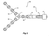
Fig 2 is a top view of the assembly shown inFig 1 ; -
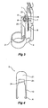
Fig 3 is a detailed view of a portion of the assembly shown inFig 1 ; -
Fig 4 is a detailed view of one embodiment of a safety catch utilized in embodiments of the anchoring system of the present invention; -
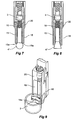
Fig 5a and 5b are cross-sectional views of the clamping and locking mechanism shown in the above Figures, taken along a planes through an axis of the screws; -
Fig 6 is a detailed perspective view of one embodiment of the nut mounted in the clamping mechanism shown in the above Figures; -
Fig 7 is a cross-sectional view of the clamping and locking mechanism of an implantable fixation assembly according to a second embodiment of the present invention; -
Fig 8 is a cross-sectional view of the clamping and locking mechanism of an implantable fixation assembly according to the third embodiment of the invention; and -
Fig 9 is a detailed perspective view of the second embodiment of the invention. - Embodiments of the present invention illustrated in the Figures are generally directed to an implantable fixation assembly for securing an implanted device such as a medical device in a patient. Implantable medical devices may include sensors, actuators and the like. Certain embodiments of the present invention comprise a bone plate having one or more extensions each having one or more holes to screw or otherwise attach the extension to an adjacent bone. The implantable fixation assembly also includes a lockable reversible clamping mechanism operable to detachably secure the medical device to the bone plate, thereby reversibly attaching the medical device to a desired bony structure in the patient's body.
- Advantageously, embodiments of the implantable fixation assembly of the present invention provide a surgeon with the capability to place a medical device at any desired location in a patient's body without having to make an incision much larger than the medical device and to easily access the clamping mechanism which may be activated near the body surface. Advantageously, the clamping mechanism is reversible; that is, it detachably secures the medical device to the patient. As such, a medical device that may need to be replaced, for example, due to an upgrade, recall, damage or other reason, can simply be exchanged by detaching the implanted medical device and securing the replacement medical device, while keeping the fixation assembly in place.
- Referring to
Fig 1 animplantable fixation assembly 30 for removably securing a device in or on a human body is shown. Theassembly 30 includes ananchor portion 1 in the form of a bone plate that is securable to a bone, abody 20 attached to theanchor portion 1 and aclamp portion 2. Thebody 20 has a pair of spacedapart legs 15 which are more clearly shown inFig 5 . Thelegs 15 are flexible and each has adistal end 15a. Theclamp portion 2 is attached to thedistal ends 15a of thelegs 15. - A clamp actuating mechanism including a driving member in the form of a
nut 4 is shown most clearly inFig 5 . The nut abuts thedistal ends 15a of the legs at a plane that is inclined so as to produce a wedging action that induces a lateral force that pulls the legs together as the nut is driven longitudinally with respect to thelegs 15. Thenut 4 is driven longitudinally by the action of thescrew 3 having athread 16. -
Bone plate 1 is configured to attach the fixation assembly to one or more selected bones of the patient.Bone plate 1 has one ormore extensions 19 configured to attach directly to a bone of the patient. Eachextension 19 comprises one ormore screw holes 6 which provide a degree of freedom to choose the number and the location of bone screws (not shown) according to the individual needs. As one of ordinary skill in the art would appreciate, the dimensions ofscrew holes 6 are suitable for the dimensions of the selected screw which, in turn, is dependent upon a variety of factors including, but not limited to, the size of the bone, the functions performed by the medical device, the mass of the medical device, etc. - Preferably, one or more of the
extensions 19 can be modified such as by bending, shortening, etc., by a surgeon in order to be adapted to the individual anatomy of the patient. Alternatively,bone plate 1 can be manufactured with a quantity ofextensions 19 each having dimensions suitable for a particular application. -
Bone plate 1 further comprises anarm portion 18 that joinsextensions 19. In the embodiment shown inFigs 1 and2 ,arm portion 18 andextensions 19 are portions of aunitary bone plate 1. In alternative embodiments, however,arm portion 18 may be separately manufactured and attached to one ormore extensions 19 to formbone plate 1.Arm portion 18 is configured to support aclamping mechanism 23 for detachably securing a medical device tobone plate 1.Clamping mechanism 23 is described in detail below. - In the embodiment shown in
Figs 1 and2 ,arm portion 18 also hasscrew holes 6 to attach a portion ofarm portion 18 to a bone. It should be appreciated, however, that in alternativeembodiments arm portion 18 does not have anyscrew holes 6. - In the embodiment shown in
Figs 1 and2 ,arm portion 18 is straight, although it need not be straight in all embodiments. In one embodiment,arm portion 18 can be bent by, for example, up to 90°, in order to placeclamp 2 in its final desired location to receive a medical device. - The clamping and locking features of
clamping mechanism 23 will now be described with reference toFigs 1-6 .Figs 1-2 have been introduced above.Fig 3 is a perspective view of one embodiment of clampingmechanism 23 of the anchoring assembly shown inFig 1 .Fig 4 is a perspective view of one embodiment of asafety catch 5 which is configured to be inserted in clampingmechanism 23 to clampingly secure the inserted medical device.Fig 5 is a cross-sectional view of theclamping mechanism 23 taken along a plane through an axis ofscrew 3 inFig 1 .Fig 6 is a detailed view of one embodiment ofnut 4 mounted in clampingmechanism 23. - Referring to
Figs 1-6 ,clamping mechanism 23 comprises aclamp portion 2 formed, in this embodiment, by a thin part-cylindrical band that has the same internal shape as the exterior surface of the medical device which is to be anchored to the patient. In the embodiment shown inFig 3 , the shape ofclamp portion 2 is cylindrical to provide a rotational degree of freedom for a medical device having a cylindrical exterior housing. As one of ordinary skill in the art would appreciate, the cross-sectional shape of the clampingportion 2 ofclamp mechanism 23 may be other than circular. For example, in alternative embodiments,clamp portion 2 has a non-symmetric cross-sectional shape such as an oval or square to prevent rotation of the installed medical device. - To anchor a medical device to the bone, the medical device is simply slid into
clamp portion 2 until a desired insertion depth is attained. Then, the medical device is secured to clampingmechanism 23 by fasteningscrew 3. In the illustrative embodiment,screw 3 has ascrew head 7 comprisingmultiple slits 8.Screw head 7 has, in this embodiment,conventional slots 25 to operably receive a screwdriver head of a surgical instrument (not shown). - With the embodiment described above, the screw is a screw drivable by a conventional screwdriver. Other embodiments of the invention may include a screw or bolt having an allen key head or any other drivable head. It should be understood that, in the context of this application and its claims, the term "screw" encompasses bolts and other cylindrical members with a helical ridge type thread.
- As best shown in
Fig 5 ,screw 3 is engaged withnut 4. Asscrew 3 is rotated clockwise, it drawsnut 4 towardsscrew head 7. To preventnut 4 from being removed by unfasteningscrew 3, its movement is limited byprojection 13 that travels in achannel 12 inbone plate 1. Through theinclined plane 17 between the cup shaped inner surface 4a ofnut 4 andlegs 15 ofclamping mechanism 23, the longitudinal force is transformed into a lateral force that tightensclamp 2. - To prevent
screw 3 from rotating, slits 8 ofscrew head 7 are to be aligned with opposinggrooves 9 inclamp mechanism 23, andsafety catch 5 is inserted intoclamping mechanism 23, as shown inFig 1 . As best shown inFigs 1 and4 , this embodiment ofsafety catch 5 comprises atab 21 with two opposingflexible legs 10 each with asmall retention portion 11 located at their distal ends. - When
safety catch 5 is inserted intogroove 9 ofclamping mechanism 2,arms 10 are positioned inslits 8 ofscrew head 7 andgrooves 9 ofclamping mechanism 2. Also, ascrew locking portion 24 oftab 21 is positioned withinslits 8 ofscrew head 7. Thus, the insertion ofsafety catch 5 locks screw 3 and secures the anchored medical device inclamp 2. As shown inFig 5 , whensafety catch 5 is in its final position,retention portions 11 ofsafety catch 5 snap in the correspondingopenings 14 inclamp mechanism 2. - By pulling on
tab 21,safety catch 5 can be removed due to the slightly inclined upper edge ofretention portions 11. As one of ordinary skill in the art would appreciate, the reversible nature ofclamping mechanism 2 may be prevented with the application of an adhesive or cement to groove 9. - In alternative embodiments of the invention illustrated in
Figs 7, 8 and 9 , a separate nut is not required. - Referring to
Figs 7 and 9 , components of a second embodiment of the invention will now be described. Thescrew 3 includes a threadedmale portion 16 that mates with a female threaded portion within thebody 20. At the end of thescrew 3 is abulbous portion 4' that engages theends 15a of thelegs 15. With this arrangement, as thescrew 3 is tightened drawing thebulbous portion 4' inwards, thelegs 15 are splayed apart causing theclamp portion 2 to close up. In this way, a medical device can be secured to the implantable fixation assembly. - Turning to
Fig 8 , a third embodiment of the invention will now be described. The third embodiment of the invention is very similar to that of the second embodiment, however thebulbous portion 4' is replaced a wedge shapedportion 4". It will be appreciated that various types ofscrews 3 could be used other than those of the types shown inFigs 5a and b ,7 and 8 . - Advantageously, embodiments of the implantable fixation assembly detachably anchor an implanted medical device to one or more bones of a patient. In addition, in those embodiments in which the
extensions 19 and anchoringarm 18 can be bent, andextensions 19 can be severed,bone plate 1 can be modified as desired to achieve the most therapeutic position and orientation of a desired implantable medical device. Furthermore, the fixation assembly is preferably sufficiently small to permit the implantation of a medical device via a narrow incision, reducing the invasiveness of the implantation procedure. It is anticipated that only minimal manipulation of the fixation assembly will be required, further reducing the likelihood that a larger incision would be necessary. - As one of ordinary skill in the art would appreciate, the implantable fixation assembly of the present invention may be implemented with any completely- or partially-implantable medical device now or later developed. For example, embodiments of the implantable fixation assembly may be used to temporarily secure stimulators, transducers, sensors, drug-delivery devices, etc. in any location in the body, including the cranium, thorax, spinal column, etc., for any therapeutic application such as neurological, cardiac, gasbrointestinal, sensory, etc. One exemplary application is to secure an embodiment of an actuator described in commonly-owned US Provisional Application entitled "implantable Actuator For Hearing Applications,"
US application No 60/613,512 US Application No 60/613,512 - It will be understood that the term "comprises" and any of its derivatives (eg. comprises, comprising) as used in this specification and its claims is to be taken to be inclusive of features to which it refers, and is not meant to exclude the presence of any additional features unless otherwise stated or implied. While the present invention has been described in terms of preferred embodiments in order to facilitate a better understanding of the invention, it should be appreciated that various modifications can be made without departing from the principles of the invention. Therefore, the invention should be understood to include all such modifications within the scope.
Claims (10)
- An implantable fixation assembly for removably securing a medical device in a human body, the assembly comprising: an anchor portion (I) securable to bone; a body (20) attached to the anchor portion, the body having a pair of spaced apart legs (15), al least one leg being flexible, each leg having a distal end (15a); a clamp portion (2) attached to the distal ends of the legs; a clamp actuating mechanism (23) comprising a driving member (3, 4, 16) that abuts the legs so as to produce a wedging action that induces a lateral force that pulls the legs together or pushes the legs apart as the driving member is driven longitudinally with respect to the legs thereby actuating the clamp portion to secure the device, wherein the actuating is reversible for selectively gripping and releasing the device, and wherein the at least one flexible leg is resiliently flexible, characterized in that the clamp portion comprises a part-cylindrical band, the band having an internal diameter that reduces as the clamp portion is actuated to grip the device.
- An assembly as claimed in claim 1 wherein the band (2) bats a first end attached towards or at the distal end (15a) of a first of the legs (15) and a second end attached towards or at the distal end (15a) of a second of the legs (15).
- An assembly as claimed in claim 2. further comprising a screw (3) having a head (7), the head shaped to receive a driver, whereby a surgeon can selectively grip and release the device using the driver.
- An assembly as claimed in claim 3 further comprising a safety catch (5), the catch operable to reversibly lock the clamp portion (2) with respect to the device.
- An assembly as claimed in claim 4 wherein the head (7) defines a plurality of longitudinally extending slits (25) for receiving a screw locking portion (21) of the safety catch.
- An assembly as claimed in claim 5 wherein the catch (5) comprises a screw locking portion (21) selectively engagable with the slits (25) of the screw head (7).
- An assembly as claimed in claim 6 wherein the catch (5) further comprises flexible fingers (10), each finger having a retention portion (4) that snaps into a recess within the legs (15) or the body (20) so as to reversibly secure the safety catch to the legs or body.
- An assembly as claimed in claim 7 wherein the anchor portion (1) defines a plurality of holes (6), the holes facilitating attachment of the anchor portion to the bone with screws.
- An assembly as claimed in claim 8 wherein the anchor portion (1) is bendable to allow a surgeon to conform the anchor portion to a particular anatomy of a patient.
- An assembly as claimed in claim 1 further comprising the device, the device having a grippable outer surface, the device and the clamp portion (2) mutually shaped to allow sliding and rotational movement of the device with respect to the clamp portion wherein a surgeon can adjust the position of the device with respect to the clamp portion before releaseably locking the device to the clamp portion.
Applications Claiming Priority (3)
| Application Number | Priority Date | Filing Date | Title |
|---|---|---|---|
| US63151204P | 2004-11-30 | 2004-11-30 | |
| US63150804P | 2004-11-30 | 2004-11-30 | |
| PCT/AU2005/001800 WO2006058367A1 (en) | 2004-11-30 | 2005-11-30 | Implantable fixation assembly for removably securing a medical device |
Publications (3)
| Publication Number | Publication Date |
|---|---|
| EP1819303A1 EP1819303A1 (en) | 2007-08-22 |
| EP1819303A4 EP1819303A4 (en) | 2011-04-27 |
| EP1819303B1 true EP1819303B1 (en) | 2012-06-27 |
Family
ID=36564669
Family Applications (1)
| Application Number | Title | Priority Date | Filing Date |
|---|---|---|---|
| EP05810605A Expired - Lifetime EP1819303B1 (en) | 2004-11-30 | 2005-11-30 | Implantable fixation assembly for removably securing a medical device |
Country Status (3)
| Country | Link |
|---|---|
| US (1) | US8235886B2 (en) |
| EP (1) | EP1819303B1 (en) |
| WO (1) | WO2006058367A1 (en) |
Cited By (1)
| Publication number | Priority date | Publication date | Assignee | Title |
|---|---|---|---|---|
| US9421387B2 (en) | 2012-09-20 | 2016-08-23 | Advanced Bionics Ag | Implantable body with a lead and with an engagement wing |
Families Citing this family (3)
| Publication number | Priority date | Publication date | Assignee | Title |
|---|---|---|---|---|
| WO2013023693A1 (en) | 2011-08-17 | 2013-02-21 | Advanced Bionics Ag | Implantable hearing instrument actuator fixation system |
| EP4424030A4 (en) | 2021-10-27 | 2026-01-07 | Cochlear Ltd | SELF-LOCKING FASTENING SYSTEM FOR A MEDICAL IMPLANT |
| CN120826255A (en) * | 2023-03-10 | 2025-10-21 | 科利耳有限公司 | Adhesive receptacle for medical implants |
Family Cites Families (18)
| Publication number | Priority date | Publication date | Assignee | Title |
|---|---|---|---|---|
| US705985A (en) * | 1900-12-19 | 1902-07-29 | Southern Rice Polishing Machine Company | Machine for cleaning rice, &c. |
| US2355901A (en) * | 1940-12-06 | 1944-08-15 | Pantex Pressing Machine Inc | Backlash resisting locking setscrew |
| US3164114A (en) * | 1962-06-12 | 1965-01-05 | Foster Wheeler Corp | Clamp for spacing and holding tube ends in a butt welding operation with means for positioning backing rings depending from the clamp |
| SU952244A1 (en) | 1980-01-14 | 1982-08-23 | Иркутский Государственный Медицинский Институт | Clamp |
| US4478546A (en) * | 1981-12-21 | 1984-10-23 | Mercer Mark J | Quick insertion and release bolt system |
| FR2633345A1 (en) | 1988-06-23 | 1989-12-29 | Ducharme Raymond | Assembly pin which is self-locking by means of expansion, and adjustable pulling-together loads, for surgical or other consolidation |
| US4896663A (en) * | 1988-10-14 | 1990-01-30 | Boehringer Mannheim Corporation | Self centering femoral drill jig |
| DE19532388C1 (en) * | 1995-09-01 | 1996-12-19 | Voith Sulzer Papiermasch Gmbh | Appts for coating moving paper or cardboard web |
| DE19618964C2 (en) * | 1996-05-10 | 1999-12-16 | Implex Hear Tech Ag | Implantable positioning and fixing system for actuator and sensory implants |
| DE19915684B4 (en) * | 1999-04-07 | 2005-12-01 | Phonak Ag | Implantable positioning and fixation system for actuator and sensory implants |
| DE19935029C2 (en) * | 1999-07-26 | 2003-02-13 | Phonak Ag Staefa | Implantable arrangement for mechanically coupling a driver part to a coupling point |
| USD433928S (en) * | 1999-11-23 | 2000-11-21 | Alcone Jerry M | Header bolt assembly |
| DE10047388C1 (en) * | 2000-09-25 | 2002-01-10 | Implex Hear Tech Ag | Implantable hearing system, includes a detachable coupling for securing and locating a transducer and a micro-manipulator |
| DE60127920T2 (en) * | 2000-11-13 | 2007-08-02 | Benoist Girard Sas | Target device for transfemoral osteotomy |
| US6585736B2 (en) * | 2001-09-19 | 2003-07-01 | Mohammed A. Hajianpour | Device for external fixation of a fractured radius with simultaneous clamping of multiple pins and with a fixture for applying extension to distal bone fragments |
| US6705985B2 (en) * | 2001-09-28 | 2004-03-16 | Otologics Llc | Apparatus and method for ossicular fixation of implantable hearing aid actuator |
| US6709433B1 (en) * | 2001-12-20 | 2004-03-23 | Biomet, Inc. | Bridging/non-bridging external bone fixator |
| US6740086B2 (en) * | 2002-04-18 | 2004-05-25 | Spinal Innovations, Llc | Screw and rod fixation assembly and device |
-
2005
- 2005-11-30 EP EP05810605A patent/EP1819303B1/en not_active Expired - Lifetime
- 2005-11-30 US US11/719,689 patent/US8235886B2/en not_active Expired - Fee Related
- 2005-11-30 WO PCT/AU2005/001800 patent/WO2006058367A1/en not_active Ceased
Cited By (1)
| Publication number | Priority date | Publication date | Assignee | Title |
|---|---|---|---|---|
| US9421387B2 (en) | 2012-09-20 | 2016-08-23 | Advanced Bionics Ag | Implantable body with a lead and with an engagement wing |
Also Published As
| Publication number | Publication date |
|---|---|
| EP1819303A4 (en) | 2011-04-27 |
| US8235886B2 (en) | 2012-08-07 |
| WO2006058367A1 (en) | 2006-06-08 |
| EP1819303A1 (en) | 2007-08-22 |
| US20080300596A1 (en) | 2008-12-04 |
Similar Documents
| Publication | Publication Date | Title |
|---|---|---|
| US6755834B2 (en) | Cranial flap fixation device | |
| KR100604453B1 (en) | Orthopedic System with Detachable Bone Anchors | |
| AU753521B2 (en) | Bone plate and bone screw guide mechanism | |
| JP4536118B2 (en) | Spine implant with a wide range of multiaxial fastener assemblies | |
| CN100594845C (en) | Percutaneous Access Device and Bone Anchor Assembly | |
| US7736380B2 (en) | Cervical plate system | |
| JP5628675B2 (en) | Nail / plate combination | |
| ES2383509T3 (en) | Polyaxial bone screw with spike joint pressure insert and method | |
| US5976142A (en) | Apparatus and method for distraction osteogenesis of small alveolar bone | |
| US20040106924A1 (en) | Longitudinal plate assembly having an adjustable length | |
| EP2948072B1 (en) | Caps for implants and implant assemblies | |
| WO2007136452A2 (en) | Rotolock cervical plate locking mechanism | |
| JPS62159647A (en) | Apparatus for fixing fractured femule | |
| JPH07255739A (en) | Screw for spine of which angle can be changed | |
| US20040210232A1 (en) | Guide device and plate inserter | |
| US9597122B2 (en) | Occipital fixation assembly, system and method for attaching the same | |
| EP3082631B1 (en) | Intramedullary device for mid-shaft clavicle fractures | |
| AU2018250340B2 (en) | Transverse connector | |
| CZ2003936A3 (en) | Orthopedic system | |
| US8235886B2 (en) | Implantable fixation assembly for removably securing medical device | |
| JP3130560B2 (en) | Bracing system | |
| WO2021130730A1 (en) | Bone anchor for fracture fixation |
Legal Events
| Date | Code | Title | Description |
|---|---|---|---|
| PUAI | Public reference made under article 153(3) epc to a published international application that has entered the european phase |
Free format text: ORIGINAL CODE: 0009012 |
|
| 17P | Request for examination filed |
Effective date: 20070620 |
|
| AK | Designated contracting states |
Kind code of ref document: A1 Designated state(s): AT BE BG CH CY CZ DE DK EE ES FI FR GB GR HU IE IS IT LI LT LU LV MC NL PL PT RO SE SI SK TR |
|
| RAP1 | Party data changed (applicant data changed or rights of an application transferred) |
Owner name: COCHLEAR ACOUSTICS LTD |
|
| DAX | Request for extension of the european patent (deleted) | ||
| RAP1 | Party data changed (applicant data changed or rights of an application transferred) |
Owner name: ADVANCED BIONICS AG |
|
| A4 | Supplementary search report drawn up and despatched |
Effective date: 20110324 |
|
| GRAP | Despatch of communication of intention to grant a patent |
Free format text: ORIGINAL CODE: EPIDOSNIGR1 |
|
| GRAS | Grant fee paid |
Free format text: ORIGINAL CODE: EPIDOSNIGR3 |
|
| GRAA | (expected) grant |
Free format text: ORIGINAL CODE: 0009210 |
|
| AK | Designated contracting states |
Kind code of ref document: B1 Designated state(s): AT BE BG CH CY CZ DE DK EE ES FI FR GB GR HU IE IS IT LI LT LU LV MC NL PL PT RO SE SI SK TR |
|
| REG | Reference to a national code |
Ref country code: GB Ref legal event code: FG4D |
|
| REG | Reference to a national code |
Ref country code: CH Ref legal event code: EP |
|
| REG | Reference to a national code |
Ref country code: AT Ref legal event code: REF Ref document number: 563720 Country of ref document: AT Kind code of ref document: T Effective date: 20120715 |
|
| REG | Reference to a national code |
Ref country code: IE Ref legal event code: FG4D |
|
| REG | Reference to a national code |
Ref country code: DE Ref legal event code: R096 Ref document number: 602005034969 Country of ref document: DE Effective date: 20120823 |
|
| PG25 | Lapsed in a contracting state [announced via postgrant information from national office to epo] |
Ref country code: SE Free format text: LAPSE BECAUSE OF FAILURE TO SUBMIT A TRANSLATION OF THE DESCRIPTION OR TO PAY THE FEE WITHIN THE PRESCRIBED TIME-LIMIT Effective date: 20120627 Ref country code: FI Free format text: LAPSE BECAUSE OF FAILURE TO SUBMIT A TRANSLATION OF THE DESCRIPTION OR TO PAY THE FEE WITHIN THE PRESCRIBED TIME-LIMIT Effective date: 20120627 Ref country code: LT Free format text: LAPSE BECAUSE OF FAILURE TO SUBMIT A TRANSLATION OF THE DESCRIPTION OR TO PAY THE FEE WITHIN THE PRESCRIBED TIME-LIMIT Effective date: 20120627 |
|
| REG | Reference to a national code |
Ref country code: NL Ref legal event code: VDEP Effective date: 20120627 |
|
| REG | Reference to a national code |
Ref country code: AT Ref legal event code: MK05 Ref document number: 563720 Country of ref document: AT Kind code of ref document: T Effective date: 20120627 |
|
| REG | Reference to a national code |
Ref country code: LT Ref legal event code: MG4D Effective date: 20120627 |
|
| PG25 | Lapsed in a contracting state [announced via postgrant information from national office to epo] |
Ref country code: GR Free format text: LAPSE BECAUSE OF FAILURE TO SUBMIT A TRANSLATION OF THE DESCRIPTION OR TO PAY THE FEE WITHIN THE PRESCRIBED TIME-LIMIT Effective date: 20120928 Ref country code: LV Free format text: LAPSE BECAUSE OF FAILURE TO SUBMIT A TRANSLATION OF THE DESCRIPTION OR TO PAY THE FEE WITHIN THE PRESCRIBED TIME-LIMIT Effective date: 20120627 Ref country code: SI Free format text: LAPSE BECAUSE OF FAILURE TO SUBMIT A TRANSLATION OF THE DESCRIPTION OR TO PAY THE FEE WITHIN THE PRESCRIBED TIME-LIMIT Effective date: 20120627 |
|
| PG25 | Lapsed in a contracting state [announced via postgrant information from national office to epo] |
Ref country code: CY Free format text: LAPSE BECAUSE OF FAILURE TO SUBMIT A TRANSLATION OF THE DESCRIPTION OR TO PAY THE FEE WITHIN THE PRESCRIBED TIME-LIMIT Effective date: 20120627 Ref country code: BE Free format text: LAPSE BECAUSE OF FAILURE TO SUBMIT A TRANSLATION OF THE DESCRIPTION OR TO PAY THE FEE WITHIN THE PRESCRIBED TIME-LIMIT Effective date: 20120627 Ref country code: SK Free format text: LAPSE BECAUSE OF FAILURE TO SUBMIT A TRANSLATION OF THE DESCRIPTION OR TO PAY THE FEE WITHIN THE PRESCRIBED TIME-LIMIT Effective date: 20120627 Ref country code: IS Free format text: LAPSE BECAUSE OF FAILURE TO SUBMIT A TRANSLATION OF THE DESCRIPTION OR TO PAY THE FEE WITHIN THE PRESCRIBED TIME-LIMIT Effective date: 20121027 Ref country code: EE Free format text: LAPSE BECAUSE OF FAILURE TO SUBMIT A TRANSLATION OF THE DESCRIPTION OR TO PAY THE FEE WITHIN THE PRESCRIBED TIME-LIMIT Effective date: 20120627 Ref country code: RO Free format text: LAPSE BECAUSE OF FAILURE TO SUBMIT A TRANSLATION OF THE DESCRIPTION OR TO PAY THE FEE WITHIN THE PRESCRIBED TIME-LIMIT Effective date: 20120627 Ref country code: CZ Free format text: LAPSE BECAUSE OF FAILURE TO SUBMIT A TRANSLATION OF THE DESCRIPTION OR TO PAY THE FEE WITHIN THE PRESCRIBED TIME-LIMIT Effective date: 20120627 Ref country code: AT Free format text: LAPSE BECAUSE OF FAILURE TO SUBMIT A TRANSLATION OF THE DESCRIPTION OR TO PAY THE FEE WITHIN THE PRESCRIBED TIME-LIMIT Effective date: 20120627 |
|
| PG25 | Lapsed in a contracting state [announced via postgrant information from national office to epo] |
Ref country code: PL Free format text: LAPSE BECAUSE OF FAILURE TO SUBMIT A TRANSLATION OF THE DESCRIPTION OR TO PAY THE FEE WITHIN THE PRESCRIBED TIME-LIMIT Effective date: 20120627 Ref country code: PT Free format text: LAPSE BECAUSE OF FAILURE TO SUBMIT A TRANSLATION OF THE DESCRIPTION OR TO PAY THE FEE WITHIN THE PRESCRIBED TIME-LIMIT Effective date: 20121029 Ref country code: IT Free format text: LAPSE BECAUSE OF FAILURE TO SUBMIT A TRANSLATION OF THE DESCRIPTION OR TO PAY THE FEE WITHIN THE PRESCRIBED TIME-LIMIT Effective date: 20120627 |
|
| PGFP | Annual fee paid to national office [announced via postgrant information from national office to epo] |
Ref country code: GB Payment date: 20121116 Year of fee payment: 8 |
|
| PG25 | Lapsed in a contracting state [announced via postgrant information from national office to epo] |
Ref country code: NL Free format text: LAPSE BECAUSE OF FAILURE TO SUBMIT A TRANSLATION OF THE DESCRIPTION OR TO PAY THE FEE WITHIN THE PRESCRIBED TIME-LIMIT Effective date: 20120627 |
|
| PG25 | Lapsed in a contracting state [announced via postgrant information from national office to epo] |
Ref country code: DK Free format text: LAPSE BECAUSE OF FAILURE TO SUBMIT A TRANSLATION OF THE DESCRIPTION OR TO PAY THE FEE WITHIN THE PRESCRIBED TIME-LIMIT Effective date: 20120627 Ref country code: ES Free format text: LAPSE BECAUSE OF FAILURE TO SUBMIT A TRANSLATION OF THE DESCRIPTION OR TO PAY THE FEE WITHIN THE PRESCRIBED TIME-LIMIT Effective date: 20121008 |
|
| PLBE | No opposition filed within time limit |
Free format text: ORIGINAL CODE: 0009261 |
|
| STAA | Information on the status of an ep patent application or granted ep patent |
Free format text: STATUS: NO OPPOSITION FILED WITHIN TIME LIMIT |
|
| 26N | No opposition filed |
Effective date: 20130328 |
|
| REG | Reference to a national code |
Ref country code: CH Ref legal event code: PL |
|
| REG | Reference to a national code |
Ref country code: DE Ref legal event code: R097 Ref document number: 602005034969 Country of ref document: DE Effective date: 20130328 |
|
| PG25 | Lapsed in a contracting state [announced via postgrant information from national office to epo] |
Ref country code: BG Free format text: LAPSE BECAUSE OF FAILURE TO SUBMIT A TRANSLATION OF THE DESCRIPTION OR TO PAY THE FEE WITHIN THE PRESCRIBED TIME-LIMIT Effective date: 20120927 Ref country code: LI Free format text: LAPSE BECAUSE OF NON-PAYMENT OF DUE FEES Effective date: 20121130 Ref country code: CH Free format text: LAPSE BECAUSE OF NON-PAYMENT OF DUE FEES Effective date: 20121130 |
|
| REG | Reference to a national code |
Ref country code: IE Ref legal event code: MM4A |
|
| PG25 | Lapsed in a contracting state [announced via postgrant information from national office to epo] |
Ref country code: IE Free format text: LAPSE BECAUSE OF NON-PAYMENT OF DUE FEES Effective date: 20121130 |
|
| PG25 | Lapsed in a contracting state [announced via postgrant information from national office to epo] |
Ref country code: TR Free format text: LAPSE BECAUSE OF FAILURE TO SUBMIT A TRANSLATION OF THE DESCRIPTION OR TO PAY THE FEE WITHIN THE PRESCRIBED TIME-LIMIT Effective date: 20120627 Ref country code: MC Free format text: LAPSE BECAUSE OF NON-PAYMENT OF DUE FEES Effective date: 20121130 |
|
| PG25 | Lapsed in a contracting state [announced via postgrant information from national office to epo] |
Ref country code: LU Free format text: LAPSE BECAUSE OF NON-PAYMENT OF DUE FEES Effective date: 20121130 |
|
| GBPC | Gb: european patent ceased through non-payment of renewal fee |
Effective date: 20131130 |
|
| PG25 | Lapsed in a contracting state [announced via postgrant information from national office to epo] |
Ref country code: HU Free format text: LAPSE BECAUSE OF FAILURE TO SUBMIT A TRANSLATION OF THE DESCRIPTION OR TO PAY THE FEE WITHIN THE PRESCRIBED TIME-LIMIT Effective date: 20051130 |
|
| PG25 | Lapsed in a contracting state [announced via postgrant information from national office to epo] |
Ref country code: GB Free format text: LAPSE BECAUSE OF NON-PAYMENT OF DUE FEES Effective date: 20131130 |
|
| REG | Reference to a national code |
Ref country code: FR Ref legal event code: PLFP Year of fee payment: 11 |
|
| PGFP | Annual fee paid to national office [announced via postgrant information from national office to epo] |
Ref country code: DE Payment date: 20151125 Year of fee payment: 11 |
|
| PGFP | Annual fee paid to national office [announced via postgrant information from national office to epo] |
Ref country code: FR Payment date: 20151023 Year of fee payment: 11 |
|
| REG | Reference to a national code |
Ref country code: DE Ref legal event code: R119 Ref document number: 602005034969 Country of ref document: DE |
|
| REG | Reference to a national code |
Ref country code: FR Ref legal event code: ST Effective date: 20170731 |
|
| PG25 | Lapsed in a contracting state [announced via postgrant information from national office to epo] |
Ref country code: FR Free format text: LAPSE BECAUSE OF NON-PAYMENT OF DUE FEES Effective date: 20161130 |
|
| PG25 | Lapsed in a contracting state [announced via postgrant information from national office to epo] |
Ref country code: DE Free format text: LAPSE BECAUSE OF NON-PAYMENT OF DUE FEES Effective date: 20170601 |