EP1819035A2 - Energiewandlungssystem mit einstellbarer Luftspaltdistanz und entsprechendes Verfahren - Google Patents
Energiewandlungssystem mit einstellbarer Luftspaltdistanz und entsprechendes Verfahren Download PDFInfo
- Publication number
- EP1819035A2 EP1819035A2 EP07101866A EP07101866A EP1819035A2 EP 1819035 A2 EP1819035 A2 EP 1819035A2 EP 07101866 A EP07101866 A EP 07101866A EP 07101866 A EP07101866 A EP 07101866A EP 1819035 A2 EP1819035 A2 EP 1819035A2
- Authority
- EP
- European Patent Office
- Prior art keywords
- electrode
- gap distance
- energy
- amplitude
- distance
- Prior art date
- Legal status (The legal status is an assumption and is not a legal conclusion. Google has not performed a legal analysis and makes no representation as to the accuracy of the status listed.)
- Withdrawn
Links
Images




Classifications
-
- H—ELECTRICITY
- H02—GENERATION; CONVERSION OR DISTRIBUTION OF ELECTRIC POWER
- H02N—ELECTRIC MACHINES NOT OTHERWISE PROVIDED FOR
- H02N1/00—Electrostatic generators or motors using a solid moving electrostatic charge carrier
- H02N1/06—Influence generators
- H02N1/08—Influence generators with conductive charge carrier, i.e. capacitor machines
Definitions
- the present invention relates to a system capable of recovering mechanical energy from the movements of the environment (vibrations, shocks, flows, etc.) to convert it into electrical energy, using the principle of electrostatic conversion. .
- the known mechanical vibration energy recovery systems generally comprise a base fixed rigidly to a moving support, a movable part performing, because of its inertia, a relative displacement with respect to this fixed part, a flexible connection allowing a relative displacement between the fixed and mobile parts and a converter for transforming the mechanical energy of the moving part to recover it in a different form (electrical for example).
- the distance separating at rest the fixed electrode and the moving electrode is called the gap distance. This distance is fixed for each of the systems described above.
- the amplitude of displacement of the moving electrode relative to the moving electrode is invariable, it is determined during the manufacture of the system.
- Maximum allowable vibration amplitude corresponds, in each case, to the value of the air gap at rest between the fixed part and the moving part.
- the structures of known energy conversion systems are designed to be perfectly adapted to a well-defined environment in terms of amplitude, vibration and deformation. In fact, these structures become less effective or even unusable for environments where these parameters are caused to vary over time.
- the electrical energy recovered during the displacement of the moving part depends on the capacity variation appearing during this movement.
- This energy is directly proportional to the voltages under which one injects and recovers the charge on the capacitor, as well as to the variation of capacity obtained during this movement.
- the laws giving the value of the capacitance as a function of the relative position X of the mobile part and of the fixed part are of the type 1 / (X- ⁇ ) or 1 / (X- ⁇ ) 2 , where ⁇ is the value of the distance gap at rest.
- the capacity is therefore minimal at rest when X is zero, and maximum when the amplitude of the movement approaches the value of the gap distance.
- the fixed and mobile electrodes are as close as possible to one another, which maximizes the maximum capacitance C max and therefore the final variation in capacitance C max -C min .
- FIGS. 6A and 6B show the evolution of the variable capacitance as a function of sinusoidal excitation of decreasing amplitude, for a conversion structure of known type in the plane. It can be seen that the value of the maximum capacity C max decreases extremely rapidly with the amplitude of vibration: a vibration amplitude variation of a few microns, for example when going from an amplitude of 25 ⁇ m to an amplitude of 18. ⁇ m, translates into a total capacity variation from 170 pF to 70 pF. The recoverable energy is then almost divided by a factor of 3.
- a system for converting vibratory mechanical energy into electrical energy by electrostatic or capacitive conversion comprising at least one variable capacity capacitor formed by a fixed electrode and a moving electrode, and means for modifying the distance at rest between the two electrodes, so as to adapt the system to the characteristics, in particular to the amplitude of the vibrations of the external environment, and consequently to the amplitude of the vibrations of the moving electrode relative to the fixed electrode .
- the object of the invention makes it possible to limit the influence of the variation of the vibration amplitude on the energy that can ultimately be recovered by making the air gap of the conversion structure adaptable to its environment.
- the main subject of the present invention is therefore a system for converting mechanical energy into electrical energy by electrostatic or capacitive conversion, comprising at least one fixed electrode and at least one mobile electrode capable of being vibrated by mechanical energy.
- said fixed and movable electrodes being separated at rest by an airgap distance, said system comprising means for modifying the gap distance as a function of the variation of the vibration amplitude of the moving electrode.
- the adjustment means allow adjustment before an energy conversion step.
- the adjustment means may then be formed by a set of calibrated spacers intended to be arranged between the fixed electrode and the movable electrode, one or more spacers may be used.
- the passive adjustment means may also be interposed between the fixed electrode and the moving electrode, and be able to be controlled to modify the gap distance. They are then of the rack and pinion type or slide and worm.
- the present invention also relates to a method of manufacturing a system according to the present invention, by electroerosion and laser cutting
- the adjustment means allow a modification of the gap distance during an energy conversion step.
- the adjustment means may then comprise an actuator interposed between the fixed electrode and the moving electrode and a control of said actuator.
- the actuator may be a motor, a jack, piezoelectric and / or magnetostrictive elements.
- the command is manual.
- control is autonomous and activates the actuator automatically to adapt the gap distance to the variation of the vibration amplitude.
- Manual control can also be provided, in addition to the automatic control.
- the adjustment means may comprise sensors detecting the amplitude variation of the vibrations, and in which the control comprises an electronic unit comprising concordance maps between gap distance values and gap intervals. displacement amplitude of the moving part allowing optimal energy recovery.
- the sensors are, for example accelerometer type or amplitude variation detection stop.
- the present invention also relates to a method of manufacturing a system according to the invention, wherein the actuator is integrated on silicon.
- the actuator may be formed by piezoelectric elements deposited by cathodic sputtering.
- the system may, for example, comprise a plurality of finger-shaped mobile electrodes, and wherein the fixed electrode has fingers, the fingers of the fixed electrode and the movable fingers being interdigitated.
- the movable fingers move either in their largest dimension or perpendicular to their largest dimension.
- the fingers may advantageously have a trapezoidal shape.
- FIG. 1 shows a block diagram of a system according to the present invention, comprising a fixed electrode 2 and a movable electrode 4 integral in motion with a mobile mass 6.
- the moving mass 6, and consequently the moving electrode 4 are suspended by a flexible connection means 10 to the fixed base 8.
- the fixed electrode 2 is fixedly mounted on a fixed base 8.
- the system is capable of being subjected to external mechanical excitation E, causing the displacement of the moving mass 6 and the electrode mobile 4 relative to the fixed electrode 2 in a direction F or in a direction F '.
- the fixed electrode 2 and the moving electrode 4 are separated by a distance z, the distance z can vary according to the mechanical excitation E.
- the fixed electrode 2 and the mobile electrode 4 thus form a capacitor with variable capacitance.
- the system also comprises, according to the present invention, means 12 for adjusting the airgap distance ⁇ , able to separate or bring the two electrodes 2, 4 together to increase or reduce the gap distance ⁇ respectively.
- the means 12 may be of the passive type, that is to say that they are able to set a distance ⁇ before a recovery phase of energy as a function of a planned amplitude of the mechanical excitation, or of the active type, the adjustment means can, in this case, modify the distance ⁇ during the energy recovery phase as a function of the evolution of the amplitude of the energy excitation.
- the mobile mass 6, because of its inertia, is set in relative motion with respect to the fixed base 8.
- the distance between the fixed and mobile electrodes 2 varies, causing a variation of the electrical capacity of the system.
- the energy of this movement is transformed and recovered thanks to the electric damping generated by the electrostatic forces exerted between the electrodes 2, 4 of the capacitor.
- the distance ⁇ is adapted to optimize the conversion of mechanical energy into electrical energy as a function of the amplitude of the excitation energy.
- the capacity variation of the capacitor is thus maximized throughout the operation, thus ensuring optimum energy recovery.
- FIGS. 2A and 2B show a first exemplary embodiment of a system according to the present invention, comprising a fixed part 102 connected to a source of mechanical energy, a mobile part 104, and flexible connection means 116. between the fixed part 102 and the mobile part 104.
- the movable portion 104 is able to move perpendicularly to its largest dimension in the directions F and F ', under the action of the mechanical energy to be recovered.
- the source of mechanical energy is formed by the movements of the external environment, such as vibrations, shocks, flows, etc.
- the fixed and movable portions 102 are formed by electrodes and are facing each other, thus forming a capacitor with variable capacitance.
- the two electrodes 102, 104 are separated by a variable distance z. At rest this distance z is called gap distance ⁇ .
- the system according to the present invention also comprises means 112 for modifying the gap distance ⁇ .
- the electrodes 102, 104 may be separated by an air gap distance ⁇ as a function of the adjustment imposed by the means 112.
- the mobile electrode 104 is suspended from two studs 114 fixed by the flexible connection means 116.
- a means 112 for adjusting the distance ⁇ , two in number, are interposed between the studs 114 and the fixed electrode 102. It is provided, as shown in FIG. 2, to symmetrically modify the two means 112, by adding a shim of the same thickness to maintain the fixed electrode 102 and the moving electrode 104 parallel.
- the gap distance ⁇ is modified.
- the means 112 may be formed by calipers or calibrated mechanical spacers.
- the displacement amplitude of the moving electrode 104 relative to the fixed electrode is adapted to the amplitude of the vibrations converted by the energy conversion system.
- the adjustment shims 112 used are then thicker than those set in FIG. to adjust the configuration shown in Figure 2B.
- the gap distance ⁇ 1 is then greater than the gap distance ⁇ 2 .
- the means 112 may be of the slide and worm system, or rack-and-pinion type.
- the mechanical system is interposed between the mobile part 104 and the fixed part 102.
- the pinion may be integral with the fixed part 102 and the rack integral with the movable part 104.
- the pinion meshes with the rack and causes a approximation or relative distance of the movable portion 104 and the fixed portion 102 according to its direction of rotation.
- the expected maximum amplitude of displacement can be evaluated as follows: the value of the excitation is first determined by means of an accelerometer. Then, knowing the mechanical stiffness of the system, we can deduce the displacement amplitude.
- the passive adjustment means are particularly suitable for macroscopic conversion, for example of volume of one or more cm 3 .
- This type of system can be achieved by conventional precision engineering techniques, such as EDM and laser cutting.
- EDM electrospray deposition
- the elements involved in the adjustment of the gap distance ⁇ can be made with an accuracy of the order of ⁇ m; for the adjustment of the distance, one will also find a precision of the order of the ⁇ m.
- the passive adjustment means make it possible to increase the efficiency of energy conversion, however these do not offer the possibility of modifying the value of the gap distance ⁇ during energy recovery, if the amplitude vibration was unexpectedly changing.
- FIGS. 3A and 3B show a second embodiment of a conversion system according to the present invention, comprising a fixed part 202 and a mobile part 204.
- the fixed portion 202 and the movable portion 204 respectively comprise interdigitated fingers 208, 210 forming electrodes opposite.
- each pair of faces of fingers 208, 210 facing each other forms a capacitor with variable capacitance.
- the movable portion 204 can move in a direction orthogonal to the axis of the fingers 208, 210, in a direction F or in a direction F '.
- the fingers 208, 210 advantageously have a trapezoidal profile so as to facilitate the adjustment of the gap distance ⁇ .
- the displacement of the mobile electrode by contribution to the fixed electrode that is to say that it is along the axis of the fingers or orthogonal to it
- Any finger shape may be suitable, for example rectangular or rounded fingers.
- the system also comprises means 212 for modifying the gap distance ⁇ .
- means 212 for modifying the gap distance ⁇ can be formed by mechanical calli or spacers calibrated depending on the application, or by more complex mechanical devices as described above.
- This type of means allows a passive adjustment of the system, as described in connection with FIG.
- the spacer in the configuration of FIG. 3A has a thickness d 1 greater than the thickness d 2 of the spacer of FIG. 3B, thus the gap distance ⁇ 1 is greater than the gap distance ⁇ 2 .
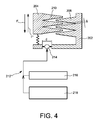
- FIG. 4 schematically shows a system for converting energy comprising active control means.
- the adjustment means 212 comprise an actuator 214 for adjusting the air gap distance ⁇ disposed between the mobile part 204 and the fixed part 202.
- This actuator 214 can be of any type, such as for example a motor, a jack, piezoelectric elements and / or magnetostrictive elements.
- the actuator 214 is disposed between the movable portion 204 and the fixed portion 202, so that, when the actuator 214 is activated, cause the approximation or removal of the fixed and movable parts.
- the adjustment means 212 also comprise an automatic control 218 and an optional external manual control 216.
- Automatic control 218 uses a built-in feedback in the system.
- the manual control can, for example, be used to make a first rough preset.
- the adjustment means comprise sensors (not shown) capable of measuring in real time, or at times defined in advance by a user, the evolution of the amplitudes of vibrations to which the system is subjected.
- the sensors may be of the accelerometer or vibration amplitude detection stop type mounted on the mobile part 204, and measure the variations of the displacement amplitude of the mobile part 204 relative to the fixed part 202.
- an electronic unit (not shown), which comprises in memory a database, in which is associated with ranges of amplitude values of movement of the moving part, a value ⁇ gap distance, allowing optimal energy recovery.
- the mobile 204 and fixed 202 parts are separated by a distance d.
- this distance is not equal to the gap distance ⁇ . It is then also provided a map of correspondence between the value of d and the value of ⁇ .
- the gap distance ⁇ is adjusted so that it is adapted to the range of motion of the moving part.
- the present invention makes it possible to adapt the gap distance ⁇ accordingly, to maintain a significant variation in the variable capacitance whatever the amplitude of the relative displacement between the fixed and mobile electrodes 202 204.
- the active adjustment means can be implemented in macroscopic conversion systems, for which there will also be a gap adjustment accuracy of a few microns as for the passive systems described above.
- the operation of the conversion system is then autonomous and self-adaptive.
- the active adjustment means in particular the actuator (s), can also be realized using microelectronic technologies; this makes it possible to integrate both the conversion structure and the actuators, of the microactuator type for the adjustment of the air gap, in conversion systems smaller than a few mm.
- the conversion structure may, for example be integrated on silicon by methods similar to those used to produce microacchariro suggestions.
- the micro-actuators may be made, for example with piezoelectric elements, for example AlN or PZT, deposited by sputtering.
- piezoelectric elements for example AlN or PZT
- sputtering One could also consider making the microactuators from magnetostrictive thin films.
- the electronic unit which manages the active means of adjustment, can be performed independently in a discrete manner and / or integrated, to minimize the overall size of the energy recovery system.
- the active adjustment means are also adapted to allow passive type adjustment of the conversion system. To do this, simply program the electronic unit, so that it activates the actuator so that it adjusts the gap distance to a given value before an energy conversion phase, and at that to maintain it throughout the conversion phase.
- the setting means may be adapted to set the interface distance to a fixed value at rest, so at each start of a recovery step the system is in a predetermined configuration. It can also be provided that the adjustment distance remains equal to the distance set at the end of the previous energy recovery step.
- FIG. 5 a flow diagram of the operation of the system of FIG. 4 can be seen.
- step 300 the system checks whether it detects the application of an external force, by moving the moving part relative to the fixed part.
- step 310 during which the energy recovery starts.
- the mobile electrode or electrodes move towards and away from the fixed part alternately.
- step 310 the sensors measure the amplitude of displacement of the moving part.
- step 320 the electronic unit compares the value of the amplitude with the pre-recorded values, and determines a distance value d, and therefore an optimum gap distance value.
- step 330 is performed in which the electronic unit instructs the actuator to increase or decrease the distance d, which consequently modifies the gap distance according to the conclusions of the comparison.
Landscapes
- Engineering & Computer Science (AREA)
- Power Engineering (AREA)
- Micromachines (AREA)
- General Electrical Machinery Utilizing Piezoelectricity, Electrostriction Or Magnetostriction (AREA)
- Apparatuses For Generation Of Mechanical Vibrations (AREA)
Applications Claiming Priority (1)
| Application Number | Priority Date | Filing Date | Title |
|---|---|---|---|
| FR0650511A FR2897486B1 (fr) | 2006-02-13 | 2006-02-13 | Systeme de conversion d'energie a distance d'entrefer variable et procede de recuperation d'energie |
Publications (2)
| Publication Number | Publication Date |
|---|---|
| EP1819035A2 true EP1819035A2 (de) | 2007-08-15 |
| EP1819035A3 EP1819035A3 (de) | 2007-09-05 |
Family
ID=37056754
Family Applications (1)
| Application Number | Title | Priority Date | Filing Date |
|---|---|---|---|
| EP07101866A Withdrawn EP1819035A3 (de) | 2006-02-13 | 2007-02-07 | Energiewandlungssystem mit einstellbarer Luftspaltdistanz und entsprechendes Verfahren |
Country Status (4)
| Country | Link |
|---|---|
| US (1) | US7781935B2 (de) |
| EP (1) | EP1819035A3 (de) |
| JP (1) | JP5230110B2 (de) |
| FR (1) | FR2897486B1 (de) |
Cited By (3)
| Publication number | Priority date | Publication date | Assignee | Title |
|---|---|---|---|---|
| WO2011042041A1 (de) * | 2009-10-05 | 2011-04-14 | Siemens Aktiengesellschaft | Mikroelektromechanischer sensor mit differentialkondensatorprinzip |
| CN102804565A (zh) * | 2009-06-23 | 2012-11-28 | 法国原子能源和替代能源委员会 | 用于放大振动运动的微机械装置 |
| WO2017060250A1 (en) * | 2015-10-05 | 2017-04-13 | Koninklijke Philips N.V. | Energy conversion system and method |
Families Citing this family (19)
| Publication number | Priority date | Publication date | Assignee | Title |
|---|---|---|---|---|
| FR2888394A1 (fr) * | 2005-07-08 | 2007-01-12 | Commissariat Energie Atomique | Dispositif capacitif a volume capacitif optimise |
| FR2897486B1 (fr) * | 2006-02-13 | 2011-07-22 | Commissariat Energie Atomique | Systeme de conversion d'energie a distance d'entrefer variable et procede de recuperation d'energie |
| FR2925792B1 (fr) * | 2007-12-21 | 2012-12-07 | Commissariat Energie Atomique | Dispositif de recuperation d'energie a electrode liquide |
| DE102008040854A1 (de) | 2008-07-30 | 2010-02-04 | Robert Bosch Gmbh | Mikromechanische Struktur sowie Verfahren zum Einstellen der Arbeitsspaltbreite einer mikromechanischen Struktur |
| US8030786B2 (en) * | 2008-08-22 | 2011-10-04 | Willowview Systems, Inc. | System for generating electrical energy from ambient energy |
| FR2936351B1 (fr) * | 2008-09-25 | 2010-10-15 | Commissariat Energie Atomique | Systeme a capacite variable a dielectrique souple. |
| CN101834545B (zh) * | 2009-03-10 | 2012-08-08 | 冯连阶 | 三相震动式陶瓷发电机 |
| FR2945835B1 (fr) | 2009-05-25 | 2016-01-22 | Commissariat Energie Atomique | Microsystemes de transformation de pressions et de compression, capteur, roue, puce, micromoteur, pile incorporant ce microsysteme et procede de fabrication de ce microsysteme |
| US8350394B2 (en) * | 2009-09-30 | 2013-01-08 | Alcatel Lucent | Energy harvester apparatus having improved efficiency |
| FR2967713B1 (fr) | 2010-11-22 | 2012-12-21 | Commissariat Energie Atomique | Microsystemes de compression ou de transformation d'une difference de pressions en deplacement |
| RU2454783C1 (ru) * | 2011-01-28 | 2012-06-27 | Владимир Андреевич Степанец | Способ генерации электроэнергии и емкостной электрополевой генератор на основе этого способа |
| KR20160006336A (ko) * | 2014-07-08 | 2016-01-19 | 삼성디스플레이 주식회사 | 트랜스듀서 및 이를 포함하는 전자 기기 |
| US9786832B2 (en) | 2015-01-05 | 2017-10-10 | Samsung Electronics Co., Ltd. | Energy harvester |
| US20160315562A1 (en) * | 2015-04-22 | 2016-10-27 | Everywhere Energy Inc. | Energy harvesting systems, apparatus, and methods |
| US10504656B2 (en) * | 2015-04-29 | 2019-12-10 | General Electric Company | Electrodes for linear switched capacitive devices |
| US9806639B2 (en) | 2015-04-29 | 2017-10-31 | General Electric Company | Dielectric fluids for linear switched capacitive devices |
| US9748867B2 (en) | 2015-08-03 | 2017-08-29 | General Electric Company | Control system for linear switched capacitive devices |
| US10815961B2 (en) * | 2018-10-01 | 2020-10-27 | Abu Dhabi Polytechnic | Ocean wave power generator with artificially intelligent controller |
| US11961684B1 (en) * | 2023-08-02 | 2024-04-16 | King Faisal University | Energy storage in a minimized variable capacitance system using capacitor with distance-movable plates |
Family Cites Families (20)
| Publication number | Priority date | Publication date | Assignee | Title |
|---|---|---|---|---|
| US2036084A (en) * | 1933-12-20 | 1936-03-31 | Gen Electric | Coupling |
| GB553353A (en) * | 1942-01-01 | 1943-05-18 | Philips Nv | Improvements in or relating to the manufacture of condenser electrodes |
| US2968031A (en) * | 1955-02-24 | 1961-01-10 | North American Aviation Inc | Electronic micrometer |
| KR100363247B1 (ko) * | 1995-10-28 | 2003-02-14 | 삼성전자 주식회사 | 진동구조물및그것의고유진동수제어방법 |
| GB2311171A (en) | 1996-03-15 | 1997-09-17 | Keystone Elec Co Ltd | Device for generating electricity from vibrations |
| JPH1198868A (ja) * | 1997-09-12 | 1999-04-09 | Terumo Corp | 静電型発電装置 |
| EP1240708A2 (de) * | 1999-11-29 | 2002-09-18 | Iolon, Inc. | Ausgeglichen mikrovorrichtung und rotierender elektrostatischer betätiger der diese verwendet |
| JP2002040045A (ja) * | 2000-07-21 | 2002-02-06 | Denso Corp | 力学量センサ |
| JP4329275B2 (ja) * | 2001-04-03 | 2009-09-09 | 株式会社デンソー | 力学量センサ |
| US6508126B2 (en) * | 2000-07-21 | 2003-01-21 | Denso Corporation | Dynamic quantity sensor having movable and fixed electrodes with high rigidity |
| US6593666B1 (en) * | 2001-06-20 | 2003-07-15 | Ambient Systems, Inc. | Energy conversion systems using nanometer scale assemblies and methods for using same |
| JP2003199313A (ja) * | 2001-12-26 | 2003-07-11 | Hiroshi Hosaka | 振動発電機 |
| DE10318733A1 (de) * | 2003-04-25 | 2004-11-11 | Robert Bosch Gmbh | Verfahren und Vorrichtung zur Energieversorgung von Sensoren |
| JP2005130624A (ja) * | 2003-10-24 | 2005-05-19 | Hitachi Ltd | 発電装置および発電方法 |
| JP2005137071A (ja) * | 2003-10-29 | 2005-05-26 | Hitachi Ltd | 振動発電装置 |
| JP2006042005A (ja) * | 2004-07-28 | 2006-02-09 | Matsushita Electric Ind Co Ltd | 電気機械共振器 |
| EP1803170B1 (de) * | 2004-10-21 | 2011-06-22 | Société de Technologie Michelin | Energiesammelvorrichtung mit einstellbarer resonanzfrequenz |
| KR100639918B1 (ko) * | 2004-12-16 | 2006-11-01 | 한국전자통신연구원 | Mems 액츄에이터 |
| FR2897486B1 (fr) * | 2006-02-13 | 2011-07-22 | Commissariat Energie Atomique | Systeme de conversion d'energie a distance d'entrefer variable et procede de recuperation d'energie |
| US7345372B2 (en) * | 2006-03-08 | 2008-03-18 | Perpetuum Ltd. | Electromechanical generator for, and method of, converting mechanical vibrational energy into electrical energy |
-
2006
- 2006-02-13 FR FR0650511A patent/FR2897486B1/fr not_active Expired - Fee Related
-
2007
- 2007-02-07 EP EP07101866A patent/EP1819035A3/de not_active Withdrawn
- 2007-02-09 JP JP2007030811A patent/JP5230110B2/ja not_active Expired - Fee Related
- 2007-02-12 US US11/705,859 patent/US7781935B2/en not_active Expired - Fee Related
Cited By (5)
| Publication number | Priority date | Publication date | Assignee | Title |
|---|---|---|---|---|
| CN102804565A (zh) * | 2009-06-23 | 2012-11-28 | 法国原子能源和替代能源委员会 | 用于放大振动运动的微机械装置 |
| CN102804565B (zh) * | 2009-06-23 | 2014-11-05 | 法国原子能源和替代能源委员会 | 用于放大振动运动的微机械装置 |
| WO2011042041A1 (de) * | 2009-10-05 | 2011-04-14 | Siemens Aktiengesellschaft | Mikroelektromechanischer sensor mit differentialkondensatorprinzip |
| WO2017060250A1 (en) * | 2015-10-05 | 2017-04-13 | Koninklijke Philips N.V. | Energy conversion system and method |
| US10958192B2 (en) | 2015-10-05 | 2021-03-23 | Koninklijke Philips N.V. | Energy conversion system and method |
Also Published As
| Publication number | Publication date |
|---|---|
| US20070188153A1 (en) | 2007-08-16 |
| FR2897486B1 (fr) | 2011-07-22 |
| JP2007221991A (ja) | 2007-08-30 |
| FR2897486A1 (fr) | 2007-08-17 |
| JP5230110B2 (ja) | 2013-07-10 |
| US7781935B2 (en) | 2010-08-24 |
| EP1819035A3 (de) | 2007-09-05 |
Similar Documents
| Publication | Publication Date | Title |
|---|---|---|
| EP1819035A2 (de) | Energiewandlungssystem mit einstellbarer Luftspaltdistanz und entsprechendes Verfahren | |
| EP2668716B1 (de) | Schaltung zur optimierung der wiederherstellung einer vibrationsenergie durch einen mechanisch-elektrischen wandler | |
| EP0017554B1 (de) | Elastische Wellen verwendender Beschleunigungsmesser | |
| EP2796884B1 (de) | Mikroelektromechanische und/oder nanoelektromechanische Struktur mit einstellbarer Qualitätsfaktor | |
| EP2647120B1 (de) | Vorrichtung zur umwandlung von mechanischer schwingungsenergie in elektrische energie | |
| WO2018127651A1 (fr) | Interface tactile comportant un capteur de force | |
| JP5816903B2 (ja) | Memsアクチュエータ付きカメラモジュール及びその駆動方法 | |
| FR2792722A1 (fr) | Capteur gyroscopique et appareil de mesure de rotation en comportant application | |
| FR2858853A1 (fr) | Accelerometre a vibrations parasites reduites par forme des electrodes amelioree | |
| WO2007080259A1 (fr) | Systeme micro-electromecanique comprenant une partie deformable et un detecteur de contrainte | |
| FR2977676A1 (fr) | Micro-systeme vibrant a boucle de controle automatique de gain, a controle integre du facteur de qualite | |
| FR2924422A1 (fr) | Dispositif a detection par jauge de contrainte piezoresistive suspendue comportant une cellule d'amplification de contrainte. | |
| EP2949621B1 (de) | Kapazitive mikro- und/ oder nanoelektronische Vorrichtung mit erhöhter Kompaktheit | |
| FR2849183A1 (fr) | Gyrometre vibrant avec asservissement de la frequence de detection sur la frequence d'excitation | |
| EP0375570B1 (de) | Vorrichtung zur Schwingungensabsorption mit einem piezoelektrischen Element | |
| FR2858854A1 (fr) | Accelerometre a vibrations parasites reduites par rappel ameliore | |
| EP3071932B1 (de) | Trägheitssensor mit verschachtelten seismischen massen und verfahren zur herstellung eines derartigen sensors | |
| FR2776065A1 (fr) | Capteur de force resonnant a elements piezo-electriques | |
| EP2504676B1 (de) | Auf mikrokräfte empfindlich reagierender resonanter kraftsensor | |
| WO2005061991A1 (fr) | Structure vibrante micro-usinee et microgyrometre associe | |
| WO2021122331A1 (fr) | Dispositif d'horloge | |
| EP3615889B1 (de) | Resonator mit konfiguration zur integration in einen trägheitswinkelsensor | |
| EP4202387B1 (de) | Verfahren und system zur bestimmung des zustands eines sensors mit nichtlinearem mechanischen verhalten basierend auf der druckamplitude | |
| WO2020008157A2 (fr) | Gyrometre micromecanique resonant performant a encombrement reduit | |
| EP1344310A1 (de) | Einrichtung mit einer mobilen struktur mit variabler starrheit, vorzugsweise mit elektrostatischer steuerung |
Legal Events
| Date | Code | Title | Description |
|---|---|---|---|
| PUAI | Public reference made under article 153(3) epc to a published international application that has entered the european phase |
Free format text: ORIGINAL CODE: 0009012 |
|
| PUAL | Search report despatched |
Free format text: ORIGINAL CODE: 0009013 |
|
| AK | Designated contracting states |
Kind code of ref document: A2 Designated state(s): AT BE BG CH CY CZ DE DK EE ES FI FR GB GR HU IE IS IT LI LT LU LV MC NL PL PT RO SE SI SK TR |
|
| AX | Request for extension of the european patent |
Extension state: AL BA HR MK YU |
|
| RIN1 | Information on inventor provided before grant (corrected) |
Inventor name: CHAILLOUT, JEAN-JACQUES Inventor name: JAGER, THOMAS Inventor name: DESPESSE, GHISLAIN |
|
| AK | Designated contracting states |
Kind code of ref document: A3 Designated state(s): AT BE BG CH CY CZ DE DK EE ES FI FR GB GR HU IE IS IT LI LT LU LV MC NL PL PT RO SE SI SK TR |
|
| AX | Request for extension of the european patent |
Extension state: AL BA HR MK YU |
|
| RAP1 | Party data changed (applicant data changed or rights of an application transferred) |
Owner name: COMMISSARIAT A L'ENERGIE ATOMIQUE |
|
| 17P | Request for examination filed |
Effective date: 20080303 |
|
| AKX | Designation fees paid |
Designated state(s): AT BE BG CH CY CZ DE DK EE ES FI FR GB GR HU IE IS IT LI LT LU LV MC NL PL PT RO SE SI SK TR |
|
| RAP1 | Party data changed (applicant data changed or rights of an application transferred) |
Owner name: COMMISSARIAT A L'ENERGIE ATOMIQUE ET AUX ENERGIES |
|
| STAA | Information on the status of an ep patent application or granted ep patent |
Free format text: STATUS: EXAMINATION IS IN PROGRESS |
|
| STAA | Information on the status of an ep patent application or granted ep patent |
Free format text: STATUS: THE APPLICATION HAS BEEN WITHDRAWN |
|
| 17Q | First examination report despatched |
Effective date: 20170105 |
|
| 18W | Application withdrawn |
Effective date: 20170112 |