EP1818702A1 - Improvements in or relating to tube couplings for connecting a pair of conduits for carrying a cable - Google Patents
Improvements in or relating to tube couplings for connecting a pair of conduits for carrying a cable Download PDFInfo
- Publication number
- EP1818702A1 EP1818702A1 EP06256386A EP06256386A EP1818702A1 EP 1818702 A1 EP1818702 A1 EP 1818702A1 EP 06256386 A EP06256386 A EP 06256386A EP 06256386 A EP06256386 A EP 06256386A EP 1818702 A1 EP1818702 A1 EP 1818702A1
- Authority
- EP
- European Patent Office
- Prior art keywords
- throughway
- tube
- coupling
- annular
- cable
- Prior art date
- Legal status (The legal status is an assumption and is not a legal conclusion. Google has not performed a legal analysis and makes no representation as to the accuracy of the status listed.)
- Granted
Links
- 230000008878 coupling Effects 0.000 title claims abstract description 61
- 238000010168 coupling process Methods 0.000 title claims abstract description 61
- 238000005859 coupling reaction Methods 0.000 title claims abstract description 61
- 239000013307 optical fiber Substances 0.000 claims abstract description 19
- 238000007789 sealing Methods 0.000 claims abstract description 9
- 230000006835 compression Effects 0.000 claims abstract description 5
- 238000007906 compression Methods 0.000 claims abstract description 5
- 239000000463 material Substances 0.000 claims description 3
- 239000000835 fiber Substances 0.000 description 10
- 230000037431 insertion Effects 0.000 description 4
- 238000003780 insertion Methods 0.000 description 4
- 229920003023 plastic Polymers 0.000 description 3
- 238000011144 upstream manufacturing Methods 0.000 description 3
- 125000006850 spacer group Chemical group 0.000 description 2
- 230000005540 biological transmission Effects 0.000 description 1
- 230000000903 blocking effect Effects 0.000 description 1
- 238000007664 blowing Methods 0.000 description 1
- 238000004880 explosion Methods 0.000 description 1
- 239000002184 metal Substances 0.000 description 1
- 230000003287 optical effect Effects 0.000 description 1
- 230000000149 penetrating effect Effects 0.000 description 1
- 239000004033 plastic Substances 0.000 description 1
Images
Classifications
-
- H—ELECTRICITY
- H02—GENERATION; CONVERSION OR DISTRIBUTION OF ELECTRIC POWER
- H02G—INSTALLATION OF ELECTRIC CABLES OR LINES, OR OF COMBINED OPTICAL AND ELECTRIC CABLES OR LINES
- H02G3/00—Installations of electric cables or lines or protective tubing therefor in or on buildings, equivalent structures or vehicles
- H02G3/02—Details
- H02G3/06—Joints for connecting lengths of protective tubing or channels, to each other or to casings, e.g. to distribution boxes; Ensuring electrical continuity in the joint
- H02G3/0616—Joints for connecting tubing to casing
- H02G3/0625—Joints for connecting tubing to casing with means for preventing disengagement of conductors
- H02G3/0658—Joints for connecting tubing to casing with means for preventing disengagement of conductors with means constricting the conductor-insulation
-
- G—PHYSICS
- G02—OPTICS
- G02B—OPTICAL ELEMENTS, SYSTEMS OR APPARATUS
- G02B6/00—Light guides; Structural details of arrangements comprising light guides and other optical elements, e.g. couplings
- G02B6/44—Mechanical structures for providing tensile strength and external protection for fibres, e.g. optical transmission cables
- G02B6/4439—Auxiliary devices
- G02B6/4459—Ducts; Conduits; Hollow tubes for air blown fibres
-
- G—PHYSICS
- G02—OPTICS
- G02B—OPTICAL ELEMENTS, SYSTEMS OR APPARATUS
- G02B6/00—Light guides; Structural details of arrangements comprising light guides and other optical elements, e.g. couplings
- G02B6/46—Processes or apparatus adapted for installing or repairing optical fibres or optical cables
- G02B6/50—Underground or underwater installation; Installation through tubing, conduits or ducts
- G02B6/52—Underground or underwater installation; Installation through tubing, conduits or ducts using fluid, e.g. air
Definitions
- This invention relates to tube couplings for connecting a pair of conduits through which a cable extends and more particularly although not exclusively for connecting a pair of conduits through which an optical fibre cable extends.
- Optical fibres are now commonly used for voice and data transmission lines.
- Optical fibre bundles are usually laid in conduiting to protect the fibres whether passing through underground channels or within buildings. Lengths of plastic conduit are provided coupled together by push-in tube coupling. The fibre is delivered through the conduiting by high pressure air which acts on a roughened surface of the fibre and draws the fibres through the conduiting. Once the fibre has been laid in the conduiting, it is desirable to be able to create a seal between the coupling and fibre to prevent passage of gas along the conduiting. Gas can enter the conduiting from a leak in the ground outside a building and if it is allowed to enter the conduiting and travel into the building to which the conduiting leads, there is a risk of a gas build up and possible explosion. There is therefore a need to isolate the interior of the conduit leading into the building from the rest of the conduit.
- EP-A-0363188 discloses a tube coupling for connecting conduiting in which an optical fibre is laid.
- the coupling includes a complex form seal located in the coupling having end portions to receive and seal with conduit ends inserted into the coupling and a central section which can be displaced as air pressure to allow passage of an optical fibre through the coupling and which springs back to engage the tube once the air pressure is released. With this arrangement it is difficult to ensure an effective reliable seal with the fibre.
- This invention provides a tube coupling for connection to a conduit through which a cable (e.g. an optical fibre cable) may pass, the coupling comprising a coupling body having an open ended throughway to receive an end of the conduit for carrying a cable, a tube locking device in the open ends of the throughway for locking the conduit in the coupling body, the throughway having a reduced diameter section part way along the throughway with an annular step at an end of the section facing towards the open end of the throughway to receive the end of the conduit inserted into the throughway, and an annular flexible sealing member disposed adjacent the step to be forced by an end of the tube inserted into the throughway into the reduced diameter section of the throughway, the resulting compression of the annular flexible seal forcing the seal into sealing engagement with a cable extending along the throughway to provide a seal between the coupling body and cable.
- a cable e.g. an optical fibre cable
- the step at one end of the reduced diameter section with which the annular seal is engageable may be inclined to provide a ramp leading from the throughway to the reduced section to guide the seal into the reduced section when pressed by a tube being inserted into the throughway.
- the annular seal may comprise an annular sleeve of flexible material.
- annular sleeve in uncompressed state may be longer than the reduced diameter section in the throughway.
- the locking devices in the open ends of the throughway comprise collets for gripping and locking the ends of the tube.
- the collet at each end of the coupling body may comprise an annular head extending out of the throughway and having axially projecting legs extending into the throughway terminating in heads formed on their inner sides to grip a tube and engageable on their outer sides with a tapered cam surfaces formed in the throughway which forces the heads into engagement with a tube as the collet is drawn outwardly of the throughway.
- a seal may be provided for engaging the outer surface of a tube adjacent at said end of the throughway adjacent the locking device.
- an "in-line" tube coupling indicated generally at 10 for a pair of conduits for carrying an optical fibre bundle or cable.
- the fitting comprises an elongate coupling body 11 formed in a transparent plastics material to allow the inside of the body to be viewed.
- the coupling body has a throughway 12 extending between openings 13,14 at the ends of the body.
- enlarged sockets 15,16 are formed in which "push-in" type tube locking devices are provided of the type described and illustrated in our UK patent specification No. 1520742 for blocking conduit for carrying the optical fibre in the ends of the coupling body.
- each socket 15 contains a collet 17 comprising a head 18 projecting out of the socket and integrally formed with spaced axially extending arms 19 formed with enlarged heads.
- the heads have angled barbs or teeth 21 formed in metal and moulded into the head to grip and engage a tube passing through the collets.
- the outer sides of the heads 20 are engageable with a tapered cam surface 22 formed on the inner side of the socket and reducing in cross-section towards the open end of the socket.
- One of the sockets indicated at 15 of the coupling which is intended to be "upstream” in the sense in which air pressure blows an optical fibre bundle through the conduits/couplings has an enlarged cavity in which an O-ring seal 23 is located against a shoulder 24 between the cavity and the main part of the throughway 12 to seal with the outer surface of the tube. This is intended to prevent loss of air pressure between the tube and socket during the step of blowing an optical fibre through the conduit linked by the coupling.
- O-ring seals can be provided in both upstream and downstream sockets of the coupling although an O-ring seal in the upstream socket is all that is strictly necessary.
- the throughway 12 between the sockets 15,16 is formed with a short reduced diameter central section 25 having an inclined annular ramp 27 bridging the reduced diameter section and the main part of the throughway 12 on one side of the section 25 and an annular shoulder 28 on the other side of the central section and facing outwardly of the fitting through the socket 16.
- a soft flexible rubber bung or sleeve 30 is located in the coupling body next to the ramp 27.
- the inner diameter of the sleeve is comparable to the reduced diameter of the section 25 and the length of the bung is approximately twice that of the section 25. The purpose of the sleeve will become apparent below.
- Figure 2 of the drawings shows the initial insertion of a pair of tubes into the fitting from either end thereof through the collets in the end sockets and into the main part of the throughway 12.
- the tube 31 inserted through socket 15 abuts the opposite end of the bung 30 to the ramp 27.
- the other tube 32 extends into the throughway 12 and abuts the annular shoulder 28 at one end of the central section 25.
- the transparency of the coupling body greatly facilitates the operator in doing this.
- the collets in the respective sockets 15,16 at each end of the coupling body grip and lock the tube to prevent the tubes from withdrawing from the coupling body.
- the O-ring seal 23 in the socket 25 seals with the outer surface of the tube 30 extending through the socket and it will be noted that the inner surface of the tube is substantially flush with the inner surface of the bung 30 which again is substantially flush with the reduced diameter section 25 in the throughway.
- connection is now ready for delivery of an optical fibre bundle or cable through the tubes/coupling and this is done by applying air pressure to the tube at the remote end of the conduit to drive the tube through the conduit and in particular through conduit 31 into the tube coupling through the bung 30 reduced diameter section 25 and into tube 32.
- the tube 31 is pressed further into the coupling using the end of the tube to force the bung 30 into the reduced diameter section 25 of the throughway the sleeve is compressed axially between the ends of the tubes 31 and 32 at the reduced diameter section 25 and the resulting axial compression of the bung enlarges the bung radially to engage and grip between the inner diameter of the reduced section of the coupling body and the outer surface of the optical fibre.
- the drawings show a coupling with a rubber bung situated at the end of the tube location diameter in one end of the coupling which is conveniently formed from a transparent plastics.
- the coupling can be either single or double ended. In the latter case the double ends are formed co-axially or in line with one another to facilitate delivery of the optical fibre through the coupling.
- the coupling can have a spacer, which when the tube is inserted, is between the tube and the bung to help position the tube and help in the correct placement/compression of the bung.
- the coupling can be supplied with a stem-ended connector with its stem inserted into the bung end with a spacer clip mounted on the stem to correctly position the bung in its initial position to allow a fibre to be blown or pushed through the connector. Thereafter the clip can be removed or moved to another position such that the stem can be pushed up to a stop indicating full and correct insertion/sealing of the bung.
- the stem and connector body can have a series of steps or wings, etc. which, once rotated, allow further insertion to a stop to ensure correct insertion/sealing of the bung.
Landscapes
- Physics & Mathematics (AREA)
- General Physics & Mathematics (AREA)
- Optics & Photonics (AREA)
- Engineering & Computer Science (AREA)
- Architecture (AREA)
- Civil Engineering (AREA)
- Structural Engineering (AREA)
- Light Guides In General And Applications Therefor (AREA)
- Quick-Acting Or Multi-Walled Pipe Joints (AREA)
Abstract
Description
- This invention relates to tube couplings for connecting a pair of conduits through which a cable extends and more particularly although not exclusively for connecting a pair of conduits through which an optical fibre cable extends.
- Optical fibres are now commonly used for voice and data transmission lines. Optical fibre bundles are usually laid in conduiting to protect the fibres whether passing through underground channels or within buildings. Lengths of plastic conduit are provided coupled together by push-in tube coupling. The fibre is delivered through the conduiting by high pressure air which acts on a roughened surface of the fibre and draws the fibres through the conduiting. Once the fibre has been laid in the conduiting, it is desirable to be able to create a seal between the coupling and fibre to prevent passage of gas along the conduiting. Gas can enter the conduiting from a leak in the ground outside a building and if it is allowed to enter the conduiting and travel into the building to which the conduiting leads, there is a risk of a gas build up and possible explosion. There is therefore a need to isolate the interior of the conduit leading into the building from the rest of the conduit.
-
EP-A-0363188 discloses a tube coupling for connecting conduiting in which an optical fibre is laid. The coupling includes a complex form seal located in the coupling having end portions to receive and seal with conduit ends inserted into the coupling and a central section which can be displaced as air pressure to allow passage of an optical fibre through the coupling and which springs back to engage the tube once the air pressure is released. With this arrangement it is difficult to ensure an effective reliable seal with the fibre. - This invention provides a tube coupling for connection to a conduit through which a cable (e.g. an optical fibre cable) may pass, the coupling comprising a coupling body having an open ended throughway to receive an end of the conduit for carrying a cable, a tube locking device in the open ends of the throughway for locking the conduit in the coupling body, the throughway having a reduced diameter section part way along the throughway with an annular step at an end of the section facing towards the open end of the throughway to receive the end of the conduit inserted into the throughway, and an annular flexible sealing member disposed adjacent the step to be forced by an end of the tube inserted into the throughway into the reduced diameter section of the throughway, the resulting compression of the annular flexible seal forcing the seal into sealing engagement with a cable extending along the throughway to provide a seal between the coupling body and cable.
- More specifically the step at one end of the reduced diameter section with which the annular seal is engageable may be inclined to provide a ramp leading from the throughway to the reduced section to guide the seal into the reduced section when pressed by a tube being inserted into the throughway.
- In either of the above arrangements the annular seal may comprise an annular sleeve of flexible material.
- More specifically the annular sleeve in uncompressed state may be longer than the reduced diameter section in the throughway.
- In any of the above arrangements the locking devices in the open ends of the throughway comprise collets for gripping and locking the ends of the tube.
- For example the collet at each end of the coupling body may comprise an annular head extending out of the throughway and having axially projecting legs extending into the throughway terminating in heads formed on their inner sides to grip a tube and engageable on their outer sides with a tapered cam surfaces formed in the throughway which forces the heads into engagement with a tube as the collet is drawn outwardly of the throughway.
- In any of the above arrangements a seal may be provided for engaging the outer surface of a tube adjacent at said end of the throughway adjacent the locking device.
- The following is a description of some specific embodiments of the invention, reference being made to the accompanying drawings in which:
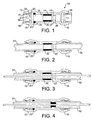
- Figure 1 is a cross-sectional view through a tube coupling for connecting lengths of optical fibre carrying conduiting with a gas block incorporated in the coupling;
- Figure 2 is a similar view to that of Figure 1 with a pair of tubes inserted into each end of the fitting with the gas block deactivated;
- Figure 3 is a similar view to that of Figure 2 with an optical fibre bundle shown blown through the fitting by air pressure from one end of the conduiting; and
- Figure 4 is a cross-sectional view through the fitting with the optical fibre passing through the fitting and the gas seal activated to prevent gas flow from one conduit to the next.
- Referring firstly to Figure 1 of the drawings, there is shown an "in-line" tube coupling indicated generally at 10 for a pair of conduits for carrying an optical fibre bundle or cable. The fitting comprises an
elongate coupling body 11 formed in a transparent plastics material to allow the inside of the body to be viewed. The coupling body has athroughway 12 extending betweenopenings - At each end of the coupling body enlarged
sockets UK patent specification No. 1520742 - More specifically, each
socket 15 contains acollet 17 comprising ahead 18 projecting out of the socket and integrally formed with spaced axially extendingarms 19 formed with enlarged heads. The heads have angled barbs orteeth 21 formed in metal and moulded into the head to grip and engage a tube passing through the collets. The outer sides of theheads 20 are engageable with atapered cam surface 22 formed on the inner side of the socket and reducing in cross-section towards the open end of the socket. After a tube has been inserted in the socket through the collet as described below, a slight movement of the tube outwardly of the socket draws the collet in an outward direction engaging theheads 20 of thearms 18 with the tube to grip and lock the tube against further outward movement. - One of the sockets indicated at 15 of the coupling which is intended to be "upstream" in the sense in which air pressure blows an optical fibre bundle through the conduits/couplings has an enlarged cavity in which an O-
ring seal 23 is located against ashoulder 24 between the cavity and the main part of thethroughway 12 to seal with the outer surface of the tube. This is intended to prevent loss of air pressure between the tube and socket during the step of blowing an optical fibre through the conduit linked by the coupling. O-ring seals can be provided in both upstream and downstream sockets of the coupling although an O-ring seal in the upstream socket is all that is strictly necessary. - The
throughway 12 between thesockets central section 25 having an inclinedannular ramp 27 bridging the reduced diameter section and the main part of thethroughway 12 on one side of thesection 25 and anannular shoulder 28 on the other side of the central section and facing outwardly of the fitting through thesocket 16. - A soft flexible rubber bung or
sleeve 30 is located in the coupling body next to theramp 27. The inner diameter of the sleeve is comparable to the reduced diameter of thesection 25 and the length of the bung is approximately twice that of thesection 25. The purpose of the sleeve will become apparent below. - Figure 2 of the drawings shows the initial insertion of a pair of tubes into the fitting from either end thereof through the collets in the end sockets and into the main part of the
throughway 12. Thetube 31 inserted throughsocket 15 abuts the opposite end of thebung 30 to theramp 27. Theother tube 32 extends into thethroughway 12 and abuts theannular shoulder 28 at one end of thecentral section 25. The transparency of the coupling body greatly facilitates the operator in doing this. The collets in therespective sockets ring seal 23 in thesocket 25 seals with the outer surface of thetube 30 extending through the socket and it will be noted that the inner surface of the tube is substantially flush with the inner surface of thebung 30 which again is substantially flush with the reduceddiameter section 25 in the throughway. - The connection is now ready for delivery of an optical fibre bundle or cable through the tubes/coupling and this is done by applying air pressure to the tube at the remote end of the conduit to drive the tube through the conduit and in particular through
conduit 31 into the tube coupling through thebung 30 reduceddiameter section 25 and intotube 32. Once the optical fibre has been positioned within the conduiting, thetube 31 is pressed further into the coupling using the end of the tube to force thebung 30 into the reduceddiameter section 25 of the throughway the sleeve is compressed axially between the ends of thetubes diameter section 25 and the resulting axial compression of the bung enlarges the bung radially to engage and grip between the inner diameter of the reduced section of the coupling body and the outer surface of the optical fibre. At the same time end portions of the bung are forced into the ends of the tubes around the optical fibre to form seals between the fibre and the inner surface of the tube as well as a seal between the fibre and reduceddiameter section 25 of the coupling body. As a result, a gas block which prevents gas from passing from conduit to conduit is created to prevent gas leaking into the conduiting at any station from penetrating along the conduiting and reaching the interior of the building to which the conduiting leads. - The drawings show a coupling with a rubber bung situated at the end of the tube location diameter in one end of the coupling which is conveniently formed from a transparent plastics. When the tube is inserted into the end adjacent the bung, the user stops inserting the tube when its end is near to the bung. Thereafter the fibre can be blown or pushed through. Finally the user can push the tube further so that it moves the bung into the smaller diameter section thereby compressing the bung on to the fibre and creating a seal.
- It will be appreciated that the coupling can be either single or double ended. In the latter case the double ends are formed co-axially or in line with one another to facilitate delivery of the optical fibre through the coupling.
- The coupling can have a spacer, which when the tube is inserted, is between the tube and the bung to help position the tube and help in the correct placement/compression of the bung.
- The coupling can be supplied with a stem-ended connector with its stem inserted into the bung end with a spacer clip mounted on the stem to correctly position the bung in its initial position to allow a fibre to be blown or pushed through the connector. Thereafter the clip can be removed or moved to another position such that the stem can be pushed up to a stop indicating full and correct insertion/sealing of the bung.
- Instead of a clip, the stem and connector body can have a series of steps or wings, etc. which, once rotated, allow further insertion to a stop to ensure correct insertion/sealing of the bung.
Claims (8)
- A tube coupling for connection to a conduit through which a cable (e.g. an optical fibre cable) may pass, the coupling comprising a coupling body having an open ended throughway to receive an end of the conduit for carrying a cable, a tube locking device in the open end of the throughway for locking the conduit in the coupling body, the throughway having a reduced diameter section part way along the throughway with an annular step at an end of the section facing towards the open end of the throughway to receive the end of the conduit inserted into the throughway, and an annular flexible sealing member disposed adjacent the step to be forced by an end of a tube inserted into the throughway into the reduced diameter section of the throughway, the resulting compression of the annular flexible seal forcing the seal into sealing engagement with a cable extending along the throughway to provide a seal between the coupling body and cable.
- A tube coupling as claimed in claim 1, wherein the annular step at one end of the reduced diameter section with which the annular seal is engageable is inclined to provide a ramp leading from the throughway to the reduced section to guide the seal into the reduced section when pressed by a tube being inserted into the throughway.
- A tube coupling as claimed in claim 1 or claim 2, wherein the annular seal comprises an annular sleeve of flexible material.
- A tube coupling as claimed in claim 3, wherein the annular sleeve in uncompressed state is longer than the reduced diameter section in the throughway.
- A tube coupling as claimed in any of the preceding claims, wherein the locking device in the open end of the throughway comprises a collet for gripping and locking the ends of the tube.
- A tube coupling as claimed in claim 5, wherein the collet in the end of the coupling body comprises an annular head extending out of the throughway and having axially projecting legs extending into the throughway terminating in heads formed on their inner sides to grip a tube and engageable on their outer sides with a tapered cam surfaces formed in the throughway which forces the heads into engagement with a tube as the collet is drawn outwardly of the throughway.
- A tube coupling as claimed in any of the preceding claims wherein a seal is provided for engaging the outer surface of a tube adjacent at said end of the throughway adjacent the locking device.
- A tube coupling as claimed in any of the preceding claims wherein the coupling is intended to connect together a pair of conduits through which the cable passes, the coupling having locking devices for conduits at both ends and the reduced diameter section having annular steps on either side facing towards the ends of the coupling body to receive the conduit ends and the annular flexible sealing member is located on one side of the reduced diameter section.
Priority Applications (1)
| Application Number | Priority Date | Filing Date | Title |
|---|---|---|---|
| PL06256386T PL1818702T3 (en) | 2006-02-10 | 2006-12-15 | Improvements in or relating to tube couplings for connecting a pair of conduits for carrying a cable |
Applications Claiming Priority (1)
| Application Number | Priority Date | Filing Date | Title |
|---|---|---|---|
| GBGB0602757.7A GB0602757D0 (en) | 2006-02-10 | 2006-02-10 | Improvements in or relating to tube couplings for connecting a pair of conduits for carrying a cable |
Publications (2)
| Publication Number | Publication Date |
|---|---|
| EP1818702A1 true EP1818702A1 (en) | 2007-08-15 |
| EP1818702B1 EP1818702B1 (en) | 2018-05-16 |
Family
ID=36119897
Family Applications (1)
| Application Number | Title | Priority Date | Filing Date |
|---|---|---|---|
| EP06256386.1A Not-in-force EP1818702B1 (en) | 2006-02-10 | 2006-12-15 | Improvements in or relating to tube couplings for connecting a pair of conduits for carrying a cable |
Country Status (7)
| Country | Link |
|---|---|
| US (1) | US7644959B2 (en) |
| EP (1) | EP1818702B1 (en) |
| AU (1) | AU2007200520B2 (en) |
| ES (1) | ES2671394T3 (en) |
| GB (1) | GB0602757D0 (en) |
| NZ (1) | NZ552176A (en) |
| PL (1) | PL1818702T3 (en) |
Cited By (10)
| Publication number | Priority date | Publication date | Assignee | Title |
|---|---|---|---|---|
| FR2920887A1 (en) * | 2007-09-07 | 2009-03-13 | Legris Sa | DEVICE FOR CONNECTING END OF GUIDE TUBES AND PROTECTING A CABLE |
| FR2946117A1 (en) * | 2010-05-11 | 2010-12-03 | Legris Sas | Device for connecting protection tubes for protecting optical fibers cable of optical transmission circuit, has sealing element arranged in end housing, where element is arranged to be brought into state under effect of axial compression |
| EP2282387A2 (en) | 2009-08-07 | 2011-02-09 | John Guest International Limited | Improvements in or relating to connectors for cable carrying conduits |
| FR2953903A1 (en) * | 2011-03-18 | 2011-06-17 | Parker Hannifin France Sas | Tube e.g. fluid transporting tube, and pipe connecting device for e.g. electric circuit, has disengaging units disengaging stop to displacement of ring to sealing contact position, and arranged to disengage from exterior of body |
| KR101074273B1 (en) | 2010-10-12 | 2011-10-19 | 케이넷(주) | Connector for micro tube |
| CN110429549A (en) * | 2017-09-18 | 2019-11-08 | 烟台知兴知识产权咨询服务有限公司 | A kind of power cable pipeline waterproof plugging device |
| NL2022841B1 (en) * | 2019-03-29 | 2020-10-06 | Filoform Bv | Protective plastic pipe end fitting system and method |
| GB2585667A (en) * | 2019-07-10 | 2021-01-20 | Reliance Worldwide Corporation Uk Ltd | A fibre optic cable connector |
| CN116125616A (en) * | 2021-11-15 | 2023-05-16 | 中冶京诚工程技术有限公司 | Optical fiber calandria, optical fiber blowing joint and optical fiber laying method |
| US11976759B2 (en) | 2019-07-10 | 2024-05-07 | Reliance Worldwide Corporation (UK) Limited | Tube coupling |
Families Citing this family (14)
| Publication number | Priority date | Publication date | Assignee | Title |
|---|---|---|---|---|
| GB0723646D0 (en) * | 2007-12-03 | 2008-01-16 | Guest John Int Ltd | Tube couplings |
| GB0809685D0 (en) * | 2008-05-28 | 2008-07-02 | Guest John Int Ltd | Improvements in or relating to tube couplings |
| FR2950948A1 (en) | 2009-10-06 | 2011-04-08 | Legris Sas | INSTANTANEOUS CONNECTION DEVICE HAVING REVERSE GUIDING AND SEALING ZONES |
| GB201010501D0 (en) | 2010-06-22 | 2010-08-04 | Guest John Int Ltd | A tube coupling |
| GB201205575D0 (en) | 2012-03-29 | 2012-05-16 | Guest John Int Ltd | Improvements in or relating to tube couplings |
| DE102012105067A1 (en) * | 2012-06-12 | 2013-12-12 | Bv Twentsche Kabelfabriek (Tkf) | Device for sealing conduit of fiber optic cable installed in building, has sealing element that is radially pressed against fiber optic cable, such that tube end is sealed against ingress of fluid passing through cable-side opening |
| US20140265305A1 (en) * | 2013-03-15 | 2014-09-18 | Steven L. Thompson | Conduit coupling system and method |
| GB201317952D0 (en) | 2013-10-10 | 2013-11-27 | Guest John Int Ltd | A connector for connecting to a tube |
| GB201317990D0 (en) | 2013-10-11 | 2013-11-27 | Guest John Int Ltd | A conncetor |
| US10302230B2 (en) | 2014-06-09 | 2019-05-28 | Eaton Intelligent Power Limited | Field serviceable conduit receivers |
| US9551445B2 (en) | 2014-06-09 | 2017-01-24 | Cooper Technologies Company | Conduit receivers |
| US9315342B1 (en) * | 2014-09-30 | 2016-04-19 | The Boeing Company | System and method for transporting wire components through pneumatic tubes between wire component processing stations |
| US11088515B2 (en) | 2017-08-31 | 2021-08-10 | Eaton Intelligent Power Limited | Press fitting for electrical conduit |
| US10948680B1 (en) * | 2018-10-09 | 2021-03-16 | Facebook, Inc. | Apparatuses, systems, and methods for fiber optic communication via duct installation |
Citations (3)
| Publication number | Priority date | Publication date | Assignee | Title |
|---|---|---|---|---|
| GB1520742A (en) * | 1975-07-30 | 1978-08-09 | Guest J D | Couplings for tubes |
| WO1996011355A1 (en) * | 1994-10-10 | 1996-04-18 | David Frederick Hawkins | Connector |
| WO2003062890A2 (en) * | 2002-01-23 | 2003-07-31 | Tyco Electronics Raychem Nv | Optical fibre tube sealing |
Family Cites Families (3)
| Publication number | Priority date | Publication date | Assignee | Title |
|---|---|---|---|---|
| GB8823427D0 (en) | 1988-10-05 | 1988-11-09 | British Telecomm | Gas seal |
| US5088804A (en) * | 1989-07-12 | 1992-02-18 | Optical Fiber Technologies, Inc. | Method and apparatus for terminating a fiber-optic cable without adhesive |
| JP2001112142A (en) | 1999-10-05 | 2001-04-20 | Higashio Mech Co Ltd | Fittings for cable piping |
-
2006
- 2006-02-10 GB GBGB0602757.7A patent/GB0602757D0/en not_active Ceased
- 2006-12-15 PL PL06256386T patent/PL1818702T3/en unknown
- 2006-12-15 ES ES06256386.1T patent/ES2671394T3/en active Active
- 2006-12-15 EP EP06256386.1A patent/EP1818702B1/en not_active Not-in-force
- 2006-12-19 NZ NZ552176A patent/NZ552176A/en not_active IP Right Cessation
-
2007
- 2007-01-05 US US11/620,392 patent/US7644959B2/en not_active Expired - Fee Related
- 2007-02-07 AU AU2007200520A patent/AU2007200520B2/en not_active Ceased
Patent Citations (3)
| Publication number | Priority date | Publication date | Assignee | Title |
|---|---|---|---|---|
| GB1520742A (en) * | 1975-07-30 | 1978-08-09 | Guest J D | Couplings for tubes |
| WO1996011355A1 (en) * | 1994-10-10 | 1996-04-18 | David Frederick Hawkins | Connector |
| WO2003062890A2 (en) * | 2002-01-23 | 2003-07-31 | Tyco Electronics Raychem Nv | Optical fibre tube sealing |
Cited By (26)
| Publication number | Priority date | Publication date | Assignee | Title |
|---|---|---|---|---|
| CN101796445B (en) * | 2007-09-07 | 2012-09-05 | 勒格里联合股份公司 | device for joining together the ends of tubes used to guide and protect optical cables |
| WO2009060148A1 (en) * | 2007-09-07 | 2009-05-14 | Legris Sa | Device for connecting the ends of cable guidance and protection tubes |
| US7887242B2 (en) | 2007-09-07 | 2011-02-15 | Legris Sas | Coupling for cable carrier tubes |
| FR2920887A1 (en) * | 2007-09-07 | 2009-03-13 | Legris Sa | DEVICE FOR CONNECTING END OF GUIDE TUBES AND PROTECTING A CABLE |
| EP2282387A2 (en) | 2009-08-07 | 2011-02-09 | John Guest International Limited | Improvements in or relating to connectors for cable carrying conduits |
| US8444325B2 (en) | 2009-08-07 | 2013-05-21 | John Guest International Limited | Connectors for cable carrying conduits |
| EP2282387A3 (en) * | 2009-08-07 | 2012-10-24 | John Guest International Limited | Improvements in or relating to connectors for cable carrying conduits |
| FR2946117A1 (en) * | 2010-05-11 | 2010-12-03 | Legris Sas | Device for connecting protection tubes for protecting optical fibers cable of optical transmission circuit, has sealing element arranged in end housing, where element is arranged to be brought into state under effect of axial compression |
| US9341803B2 (en) | 2010-05-11 | 2016-05-17 | Parker Hannifin Manufacturing France Sas | Device for connecting together tubes for protecting an optical fiber cable, a segment of an optical transmission circuit including such a device, and a sealing element for such a device |
| WO2011141517A1 (en) * | 2010-05-11 | 2011-11-17 | Parker Hannifin France Sas | Device for connecting protective tubes of a fiber-optic cable, section of an optical transmission circuit comprising such a device and sealing element for such a device |
| FR2960039A1 (en) * | 2010-05-11 | 2011-11-18 | Legris Sas | DEVICE FOR CONNECTING PROTECTION TUBES OF AN OPTICAL FIBER CABLE, TRONCON OF AN OPTICAL TRANSMISSION CIRCUIT COMPRISING SUCH A DEVICE AND SEALING ELEMENT FOR SUCH A DEVICE |
| KR101475338B1 (en) * | 2010-05-11 | 2014-12-22 | 파커 하니핀 매뉴팩쳐링 프랑스 에스에이에스 | A connection device of protective tubes of a fiber optic cable, an optical transmission circuit part including such device, and a sealing member for such device |
| CN102985863A (en) * | 2010-05-11 | 2013-03-20 | 帕克汉尼芬制造业法国联合股份公司 | Device for connecting protective tubes of a fiber-optic cable, section of an optical transmission circuit comprising such a device and sealing element for such a device |
| KR101074273B1 (en) | 2010-10-12 | 2011-10-19 | 케이넷(주) | Connector for micro tube |
| WO2012126858A1 (en) * | 2011-03-18 | 2012-09-27 | Parker Hannifin Manufacturing France Sas | Device for connecting tubes, internally provided with a mobile limit stop |
| FR2953903A1 (en) * | 2011-03-18 | 2011-06-17 | Parker Hannifin France Sas | Tube e.g. fluid transporting tube, and pipe connecting device for e.g. electric circuit, has disengaging units disengaging stop to displacement of ring to sealing contact position, and arranged to disengage from exterior of body |
| CN110429549A (en) * | 2017-09-18 | 2019-11-08 | 烟台知兴知识产权咨询服务有限公司 | A kind of power cable pipeline waterproof plugging device |
| CN110429549B (en) * | 2017-09-18 | 2020-06-05 | 南京溧水高新创业投资管理有限公司 | Waterproof plugging device of power cable pipeline |
| NL2022841B1 (en) * | 2019-03-29 | 2020-10-06 | Filoform Bv | Protective plastic pipe end fitting system and method |
| WO2020204699A1 (en) * | 2019-03-29 | 2020-10-08 | Filoform B.V. | Protective plastic pipe end fitting system and method |
| EP4368870A3 (en) * | 2019-03-29 | 2024-07-24 | Filoform B.V. | Protective plastic pipe end fitting system and method |
| GB2585667A (en) * | 2019-07-10 | 2021-01-20 | Reliance Worldwide Corporation Uk Ltd | A fibre optic cable connector |
| GB2585667B (en) * | 2019-07-10 | 2023-08-02 | Reliance Worldwide Corporation Uk Ltd | A fibre optic cable connector |
| US11976759B2 (en) | 2019-07-10 | 2024-05-07 | Reliance Worldwide Corporation (UK) Limited | Tube coupling |
| US12331863B2 (en) | 2019-07-10 | 2025-06-17 | Reliance Worldwide Corporation (UK) Limited | Tube coupling |
| CN116125616A (en) * | 2021-11-15 | 2023-05-16 | 中冶京诚工程技术有限公司 | Optical fiber calandria, optical fiber blowing joint and optical fiber laying method |
Also Published As
| Publication number | Publication date |
|---|---|
| AU2007200520A1 (en) | 2007-08-30 |
| EP1818702B1 (en) | 2018-05-16 |
| PL1818702T3 (en) | 2018-10-31 |
| GB0602757D0 (en) | 2006-03-22 |
| US7644959B2 (en) | 2010-01-12 |
| NZ552176A (en) | 2007-10-26 |
| US20070200344A1 (en) | 2007-08-30 |
| AU2007200520B2 (en) | 2013-01-31 |
| ES2671394T3 (en) | 2018-06-06 |
Similar Documents
| Publication | Publication Date | Title |
|---|---|---|
| AU2007200520B2 (en) | Improvements in or relating to tube couplings for connecting a pair of conduits for carrying a cable | |
| US8444325B2 (en) | Connectors for cable carrying conduits | |
| CN102782383B (en) | valve connection | |
| CN103354884B (en) | quick connector assembly | |
| CN102066822B (en) | Mechanical Pipe Fitting Devices | |
| US7811278B2 (en) | Fluid connector | |
| CN101377558B (en) | Modified pre-ferrulized communication cable assembly and installation method | |
| US20120104749A1 (en) | Tube coupling | |
| CN101952633B (en) | Grip ring for fitting | |
| CN106715993B (en) | Tube connector | |
| US8991023B2 (en) | PTC fitting cartridge | |
| US7131671B2 (en) | Transparent coupling | |
| CN202710795U (en) | Connector used in optical fiber | |
| EP3309439B1 (en) | Pipe fitting with inner and outer seals | |
| CN101796445B (en) | device for joining together the ends of tubes used to guide and protect optical cables | |
| EP1694997B1 (en) | Device for connection to an end of a corrugated pipe | |
| US20030152335A1 (en) | Sleeve for fixing optical cables | |
| CN220581940U (en) | a joint | |
| MXPA95003908A (en) | Fast connector with control valve or retensionactivated by t | |
| WO1996035072A1 (en) | Fast operated pipe coupling |
Legal Events
| Date | Code | Title | Description |
|---|---|---|---|
| PUAI | Public reference made under article 153(3) epc to a published international application that has entered the european phase |
Free format text: ORIGINAL CODE: 0009012 |
|
| AK | Designated contracting states |
Kind code of ref document: A1 Designated state(s): AT BE BG CH CY CZ DE DK EE ES FI FR GB GR HU IE IS IT LI LT LU LV MC NL PL PT RO SE SI SK TR |
|
| AX | Request for extension of the european patent |
Extension state: AL BA HR MK RS |
|
| 17P | Request for examination filed |
Effective date: 20070726 |
|
| AKX | Designation fees paid |
Designated state(s): AT BE BG CH CY CZ DE DK EE ES FI FR GB GR HU IE IS IT LI LT LU LV MC NL PL PT RO SE SI SK TR |
|
| 17Q | First examination report despatched |
Effective date: 20170119 |
|
| GRAP | Despatch of communication of intention to grant a patent |
Free format text: ORIGINAL CODE: EPIDOSNIGR1 |
|
| INTG | Intention to grant announced |
Effective date: 20171122 |
|
| GRAS | Grant fee paid |
Free format text: ORIGINAL CODE: EPIDOSNIGR3 |
|
| GRAA | (expected) grant |
Free format text: ORIGINAL CODE: 0009210 |
|
| AK | Designated contracting states |
Kind code of ref document: B1 Designated state(s): AT BE BG CH CY CZ DE DK EE ES FI FR GB GR HU IE IS IT LI LT LU LV MC NL PL PT RO SE SI SK TR |
|
| REG | Reference to a national code |
Ref country code: GB Ref legal event code: FG4D |
|
| REG | Reference to a national code |
Ref country code: CH Ref legal event code: EP |
|
| REG | Reference to a national code |
Ref country code: ES Ref legal event code: FG2A Ref document number: 2671394 Country of ref document: ES Kind code of ref document: T3 Effective date: 20180606 |
|
| REG | Reference to a national code |
Ref country code: DE Ref legal event code: R096 Ref document number: 602006055391 Country of ref document: DE |
|
| REG | Reference to a national code |
Ref country code: IE Ref legal event code: FG4D |
|
| REG | Reference to a national code |
Ref country code: AT Ref legal event code: REF Ref document number: 1000088 Country of ref document: AT Kind code of ref document: T Effective date: 20180615 |
|
| REG | Reference to a national code |
Ref country code: NL Ref legal event code: MP Effective date: 20180516 |
|
| REG | Reference to a national code |
Ref country code: LT Ref legal event code: MG4D |
|
| PG25 | Lapsed in a contracting state [announced via postgrant information from national office to epo] |
Ref country code: SE Free format text: LAPSE BECAUSE OF FAILURE TO SUBMIT A TRANSLATION OF THE DESCRIPTION OR TO PAY THE FEE WITHIN THE PRESCRIBED TIME-LIMIT Effective date: 20180516 Ref country code: LT Free format text: LAPSE BECAUSE OF FAILURE TO SUBMIT A TRANSLATION OF THE DESCRIPTION OR TO PAY THE FEE WITHIN THE PRESCRIBED TIME-LIMIT Effective date: 20180516 Ref country code: BG Free format text: LAPSE BECAUSE OF FAILURE TO SUBMIT A TRANSLATION OF THE DESCRIPTION OR TO PAY THE FEE WITHIN THE PRESCRIBED TIME-LIMIT Effective date: 20180816 Ref country code: FI Free format text: LAPSE BECAUSE OF FAILURE TO SUBMIT A TRANSLATION OF THE DESCRIPTION OR TO PAY THE FEE WITHIN THE PRESCRIBED TIME-LIMIT Effective date: 20180516 |
|
| PG25 | Lapsed in a contracting state [announced via postgrant information from national office to epo] |
Ref country code: NL Free format text: LAPSE BECAUSE OF FAILURE TO SUBMIT A TRANSLATION OF THE DESCRIPTION OR TO PAY THE FEE WITHIN THE PRESCRIBED TIME-LIMIT Effective date: 20180516 Ref country code: LV Free format text: LAPSE BECAUSE OF FAILURE TO SUBMIT A TRANSLATION OF THE DESCRIPTION OR TO PAY THE FEE WITHIN THE PRESCRIBED TIME-LIMIT Effective date: 20180516 Ref country code: GR Free format text: LAPSE BECAUSE OF FAILURE TO SUBMIT A TRANSLATION OF THE DESCRIPTION OR TO PAY THE FEE WITHIN THE PRESCRIBED TIME-LIMIT Effective date: 20180817 |
|
| REG | Reference to a national code |
Ref country code: AT Ref legal event code: MK05 Ref document number: 1000088 Country of ref document: AT Kind code of ref document: T Effective date: 20180516 |
|
| PG25 | Lapsed in a contracting state [announced via postgrant information from national office to epo] |
Ref country code: SK Free format text: LAPSE BECAUSE OF FAILURE TO SUBMIT A TRANSLATION OF THE DESCRIPTION OR TO PAY THE FEE WITHIN THE PRESCRIBED TIME-LIMIT Effective date: 20180516 Ref country code: DK Free format text: LAPSE BECAUSE OF FAILURE TO SUBMIT A TRANSLATION OF THE DESCRIPTION OR TO PAY THE FEE WITHIN THE PRESCRIBED TIME-LIMIT Effective date: 20180516 Ref country code: AT Free format text: LAPSE BECAUSE OF FAILURE TO SUBMIT A TRANSLATION OF THE DESCRIPTION OR TO PAY THE FEE WITHIN THE PRESCRIBED TIME-LIMIT Effective date: 20180516 Ref country code: RO Free format text: LAPSE BECAUSE OF FAILURE TO SUBMIT A TRANSLATION OF THE DESCRIPTION OR TO PAY THE FEE WITHIN THE PRESCRIBED TIME-LIMIT Effective date: 20180516 Ref country code: EE Free format text: LAPSE BECAUSE OF FAILURE TO SUBMIT A TRANSLATION OF THE DESCRIPTION OR TO PAY THE FEE WITHIN THE PRESCRIBED TIME-LIMIT Effective date: 20180516 |
|
| REG | Reference to a national code |
Ref country code: DE Ref legal event code: R097 Ref document number: 602006055391 Country of ref document: DE |
|
| PLBE | No opposition filed within time limit |
Free format text: ORIGINAL CODE: 0009261 |
|
| STAA | Information on the status of an ep patent application or granted ep patent |
Free format text: STATUS: NO OPPOSITION FILED WITHIN TIME LIMIT |
|
| 26N | No opposition filed |
Effective date: 20190219 |
|
| PG25 | Lapsed in a contracting state [announced via postgrant information from national office to epo] |
Ref country code: SI Free format text: LAPSE BECAUSE OF FAILURE TO SUBMIT A TRANSLATION OF THE DESCRIPTION OR TO PAY THE FEE WITHIN THE PRESCRIBED TIME-LIMIT Effective date: 20180516 |
|
| REG | Reference to a national code |
Ref country code: CH Ref legal event code: PL |
|
| PG25 | Lapsed in a contracting state [announced via postgrant information from national office to epo] |
Ref country code: MC Free format text: LAPSE BECAUSE OF FAILURE TO SUBMIT A TRANSLATION OF THE DESCRIPTION OR TO PAY THE FEE WITHIN THE PRESCRIBED TIME-LIMIT Effective date: 20180516 Ref country code: LU Free format text: LAPSE BECAUSE OF NON-PAYMENT OF DUE FEES Effective date: 20181215 |
|
| REG | Reference to a national code |
Ref country code: IE Ref legal event code: MM4A |
|
| REG | Reference to a national code |
Ref country code: BE Ref legal event code: MM Effective date: 20181231 |
|
| PG25 | Lapsed in a contracting state [announced via postgrant information from national office to epo] |
Ref country code: IE Free format text: LAPSE BECAUSE OF NON-PAYMENT OF DUE FEES Effective date: 20181215 |
|
| PG25 | Lapsed in a contracting state [announced via postgrant information from national office to epo] |
Ref country code: BE Free format text: LAPSE BECAUSE OF NON-PAYMENT OF DUE FEES Effective date: 20181231 |
|
| PG25 | Lapsed in a contracting state [announced via postgrant information from national office to epo] |
Ref country code: LI Free format text: LAPSE BECAUSE OF NON-PAYMENT OF DUE FEES Effective date: 20181231 Ref country code: CH Free format text: LAPSE BECAUSE OF NON-PAYMENT OF DUE FEES Effective date: 20181231 |
|
| PG25 | Lapsed in a contracting state [announced via postgrant information from national office to epo] |
Ref country code: TR Free format text: LAPSE BECAUSE OF FAILURE TO SUBMIT A TRANSLATION OF THE DESCRIPTION OR TO PAY THE FEE WITHIN THE PRESCRIBED TIME-LIMIT Effective date: 20180516 |
|
| PG25 | Lapsed in a contracting state [announced via postgrant information from national office to epo] |
Ref country code: PT Free format text: LAPSE BECAUSE OF FAILURE TO SUBMIT A TRANSLATION OF THE DESCRIPTION OR TO PAY THE FEE WITHIN THE PRESCRIBED TIME-LIMIT Effective date: 20180516 |
|
| PG25 | Lapsed in a contracting state [announced via postgrant information from national office to epo] |
Ref country code: CY Free format text: LAPSE BECAUSE OF FAILURE TO SUBMIT A TRANSLATION OF THE DESCRIPTION OR TO PAY THE FEE WITHIN THE PRESCRIBED TIME-LIMIT Effective date: 20180516 Ref country code: HU Free format text: LAPSE BECAUSE OF FAILURE TO SUBMIT A TRANSLATION OF THE DESCRIPTION OR TO PAY THE FEE WITHIN THE PRESCRIBED TIME-LIMIT; INVALID AB INITIO Effective date: 20061215 |
|
| PG25 | Lapsed in a contracting state [announced via postgrant information from national office to epo] |
Ref country code: IS Free format text: LAPSE BECAUSE OF FAILURE TO SUBMIT A TRANSLATION OF THE DESCRIPTION OR TO PAY THE FEE WITHIN THE PRESCRIBED TIME-LIMIT Effective date: 20180916 |
|
| PGFP | Annual fee paid to national office [announced via postgrant information from national office to epo] |
Ref country code: CZ Payment date: 20201118 Year of fee payment: 15 Ref country code: IT Payment date: 20201214 Year of fee payment: 15 Ref country code: GB Payment date: 20201218 Year of fee payment: 15 Ref country code: FR Payment date: 20201210 Year of fee payment: 15 |
|
| PGFP | Annual fee paid to national office [announced via postgrant information from national office to epo] |
Ref country code: PL Payment date: 20201117 Year of fee payment: 15 |
|
| PGFP | Annual fee paid to national office [announced via postgrant information from national office to epo] |
Ref country code: ES Payment date: 20210102 Year of fee payment: 15 Ref country code: DE Payment date: 20201221 Year of fee payment: 15 |
|
| REG | Reference to a national code |
Ref country code: DE Ref legal event code: R119 Ref document number: 602006055391 Country of ref document: DE |
|
| PG25 | Lapsed in a contracting state [announced via postgrant information from national office to epo] |
Ref country code: CZ Free format text: LAPSE BECAUSE OF NON-PAYMENT OF DUE FEES Effective date: 20211215 |
|
| GBPC | Gb: european patent ceased through non-payment of renewal fee |
Effective date: 20211215 |
|
| PG25 | Lapsed in a contracting state [announced via postgrant information from national office to epo] |
Ref country code: GB Free format text: LAPSE BECAUSE OF NON-PAYMENT OF DUE FEES Effective date: 20211215 Ref country code: DE Free format text: LAPSE BECAUSE OF NON-PAYMENT OF DUE FEES Effective date: 20220701 |
|
| PG25 | Lapsed in a contracting state [announced via postgrant information from national office to epo] |
Ref country code: FR Free format text: LAPSE BECAUSE OF NON-PAYMENT OF DUE FEES Effective date: 20211231 |
|
| PG25 | Lapsed in a contracting state [announced via postgrant information from national office to epo] |
Ref country code: IT Free format text: LAPSE BECAUSE OF NON-PAYMENT OF DUE FEES Effective date: 20211215 |
|
| REG | Reference to a national code |
Ref country code: ES Ref legal event code: FD2A Effective date: 20230216 |
|
| PG25 | Lapsed in a contracting state [announced via postgrant information from national office to epo] |
Ref country code: ES Free format text: LAPSE BECAUSE OF NON-PAYMENT OF DUE FEES Effective date: 20211216 |
|
| PG25 | Lapsed in a contracting state [announced via postgrant information from national office to epo] |
Ref country code: PL Free format text: LAPSE BECAUSE OF NON-PAYMENT OF DUE FEES Effective date: 20211215 |
|
| PG25 | Lapsed in a contracting state [announced via postgrant information from national office to epo] |
Ref country code: PL Free format text: LAPSE BECAUSE OF NON-PAYMENT OF DUE FEES Effective date: 20211215 |