EP0363188A1 - Gas seal - Google Patents
Gas seal Download PDFInfo
- Publication number
- EP0363188A1 EP0363188A1 EP89310176A EP89310176A EP0363188A1 EP 0363188 A1 EP0363188 A1 EP 0363188A1 EP 89310176 A EP89310176 A EP 89310176A EP 89310176 A EP89310176 A EP 89310176A EP 0363188 A1 EP0363188 A1 EP 0363188A1
- Authority
- EP
- European Patent Office
- Prior art keywords
- seal
- coupling portion
- transmission line
- duct
- line package
- Prior art date
- Legal status (The legal status is an assumption and is not a legal conclusion. Google has not performed a legal analysis and makes no representation as to the accuracy of the status listed.)
- Granted
Links
Images

Classifications
-
- G—PHYSICS
- G02—OPTICS
- G02B—OPTICAL ELEMENTS, SYSTEMS OR APPARATUS
- G02B6/00—Light guides; Structural details of arrangements comprising light guides and other optical elements, e.g. couplings
- G02B6/46—Processes or apparatus adapted for installing or repairing optical fibres or optical cables
- G02B6/50—Underground or underwater installation; Installation through tubing, conduits or ducts
- G02B6/52—Underground or underwater installation; Installation through tubing, conduits or ducts using fluid, e.g. air
-
- G—PHYSICS
- G02—OPTICS
- G02B—OPTICAL ELEMENTS, SYSTEMS OR APPARATUS
- G02B6/00—Light guides; Structural details of arrangements comprising light guides and other optical elements, e.g. couplings
- G02B6/44—Mechanical structures for providing tensile strength and external protection for fibres, e.g. optical transmission cables
- G02B6/4479—Manufacturing methods of optical cables
- G02B6/4485—Installing in protective tubing by fluid drag during manufacturing
Definitions
- This invention relates to a sealing arrangement for a duct, and in particular to a seal for incorporation in a duct along which an optical fibre package is installed by fibre blowing.
- a duct along which a transmission line (e.g. optical fibre) package is installed provides a continuous path along which fluid can travel.
- a transmission line e.g. optical fibre
- hazards can arise.
- gas leaks may result in the introduction of toxic or explosive gases at secondary locations, or water may leak across otherwise watertight bulkheads. Therefore, to comply with safety requirements, after a blown optical fibre installation is completed, seals or blockages are provided at intervals by perforationg the duct and injecting a resin.
- the disadvantage of this technique is that the resin forms a permanent blockage in the duct, and prevents further installation of fibre packages, or the replacement of an installed package without first removing the resined section of the duct. Removal of the resined section is time-consuming, and requires cutting of the optical fibre package, requiring subsequent replacement of a complete duct section, or the introduction of additional splices.
- the aim of the invention is to provide a seal that does not prevent subsequent installation operations.
- the present invention provides a sealing arrangement for a passageway carrying a transmission line package, the arrangement comprising a coupling portion for connection to respective passageway portions on each side thereof, a flexible seal located in the coupling portion and comprising a flexible body portion, the flexible body portion being arranged to collapse inwardly to seal around a transmission line package when the transmission line package is installed through the coupling portion, and the flexible body portion being arranged to open to permit fluid flow through the coupling portion when the fluid flow pressure exceeds a predetermined level, wherein the coupling portion is provided with at least one vent disposed so that pressure externally of the coupling portion tends to cause inward deformation of the body portion of the seal to increase its resistance to opening.
- the flexible seal comprises a tubular member having a waisted intermediate portion that forms the seal, and wherein the ends of the tubular member are secured to the inner wall of the coupling portion with the or each vent disposed between the locations at which the ends of the tubular member are secured.
- the flexible seal may have substantially flat opposing surfaces.
- Fibre blowing is the process described in our European patent specification 108590, in which lightweight transmission lines are urged along ducts by the viscous drag of a fluid, usually compressed air.
- the propellant air is typically at an initial pressure of 3 to 10 bar.
- the transmission lines typically comprise a bundle of optical fibres encased in a lightweight outer covering, and this is termed a fibre package.
- Fibre packages may also consist of single fibres or lines, and may include electrical conductors.
- Figure 1 shows a tube connector 1 provided with a flexible tubular liner 2 which constitutes a seal.
- a respective locking ring 6 is provided at each end of the connector 1, the locking rings each receiving and clamping a respective duct section 7 (see Figs. 2 to 4) along which a fibre package P is subsequently blown.
- the duct sections 7 form part of a duct along which fibre package P is to be installed.
- the ends of the duct extend into the ends of the seal 2, whereby compression of rims 5 on the ends of the connector 1 serves to seal the outer wall of duct sections 7 against the inner wall of the connector, thereby preventing escape of the installing propellant, or ingress of pressure from the external environment.
- the central portion of the connector 1 is provided with apertures 8 through which the external ambient pressure is communicated to the outer side of the seal 2.
- the seal 2 itself is moulded to have a waisted shape, the longitudinal section comprising a series of steps and curves. Alternatively, the seal 2 may have a smooth curve or taper from its ends to the centre.
- the passageway through the centre of the seal 2 is in the nature of a flattened tube, such that it acts as a blockage in the connector 1 and prevents flow of fluid below a particular pressure e.g. below 2 bar.
- the tube defined by the seal 2 has a minimum internal diameter which is less than the diameter of the fibre package P, so that, once the fibre package is installed, the central part of the seal presses around the circumference of the fibre package to form a gas-tight seal.
- the resilience and/or flexibility of the seal 2 is controlled so that the seal remains in sealing engagement around the installed fibre package P (see Figure 2) when the external pressure is normal atmospheric pressure, and the pressure within the duct is less than 2 bar (this value may be varied for different applications). If the external pressure increases, for example due to flooding on one side of a bulkhead, the seal 2 is pushed more firmly against the fibre package P, and increases the resistance of the seal to opening, so that, if there was a fracture in the duct section 7 on the high pressure (flooded) side of the seal, the duct would not provide a breach of the bulkhead because the same additional pressure maintains the seal in the closed configuration.
- Figure 3 shows how the seal 2 may deform in order to permit installation. Air, or some other propellant, is introduced into the duct at a pressure in excess of that required to deform the seal. Consequently, the seal expands rather like a balloon or inner tube, and the propellant and the fibre package P (which is urged along by the propellant) pass through the opened seal 2, which closes around the package once the introduction of pressurised propellant is discontinued.
- the seal 2 (see Figure 3) deforms by flexure of the central waisted portion in the direction of flow. In an alternative embodiment (see Figure 4), the central waisted portion of the seal 2 flexes radially outwardly.
- the geometry of the deformation may be aided or controlled by the provision of selective areas or lines of weakness or stiffening (not shown), along which flexure or resistance to flexure will preferentially occur.
- Figures 5 and 6 shown an alternative embodiment, in which a duct 11 is provided with an insert seal 12 which comprises an annular flange portion 12a and a body portion 12b.
- the flange portion 12a engages between two connecting sections of the duct 11, and is formed as part of the connector 15 that holds the duct section together.
- the connector 15 is not shown in detail in Figs. 5 and 6, but is similar to the connector 1 of Figs. 1 to 4.
- the flange portion 12b of the seal 12 is adapted to be held by the connector 15.
- the body portion 12b is made of a relatively-soft, flexible material such as a synthetic rubber, and may have a variety of configurations. For example, it may be tubular with a bore diameter substantially equal to, or less than, the minimum diameter of the transmission line package P that is to be installed along the duct 11.
- the bore of the tubular body portion 12b may be conical or tapering, with the wider end connected to the flange portion 12a.
- the tubular body portion 12b may comprise a flat body portion consisting essentially of upper and lower lip portions that press against each other in the undisturbed state.
- the body portion 12b When at rest, either before or after installation of the transmission line package P along the duct 11 the body portion 12b is collapsed inwardly as shown in Figure 6.
- the tubular body portion 12b forms a seal around the package P which is sufficiently close-fitting to prevent substantive egress (or low pressure flow) of gas along the duct 11.
- the elasticity of the seal 12 is such that, from one direction, a relatively high pressure flow of gas, such as 100 psi, will expand the seal sufficiently to enable passage of the package P (see Figure 5).
- the seal 12 expands to lie substantially flat against the sides of the duct 11, thereby presenting a minimum impedance to the passage of the package P during a blowing installation.
- the seal 12 described above with reference to Figs. 5 and 6 is unidirectional, in that it permits fibre blowing installation in one direction, but would remain resistant to opening in the opposite direction. It is envisaged that, by providing a sufficiently-thin seal, rather like a diaphragm with a central, short-lipped aperture, a seal that will open bidirectionally can be provided, with the lips inverting through the aperture to permit either direction of high pressure flow.
- Unidirectionally-opening seals may be made to have high resistance in one direction, so that blown installation can take place only from one direction, thus preventing unauthorised installation from the other direction. This may be particularly useful for maintaining integrity within a building, with it being possible to blow packages outwardly from the building, but preventing access or even high pressure fluid flow along the ducts from outside the building.
- Seal of the type described may be provided at intervals along a route to prevent low pressure leakage of contaminants along the duct. Another application is to provide such a seal in lead-through gland between two airtight chambers, for example in the watertight bulkhead of a sea-going vessel.
- a seal connection such as that shown in Figure 2 is preferably provided each side of a bulkhead, so that a leak on either side causes additional sealing by water pressure as previously described.
Landscapes
- Physics & Mathematics (AREA)
- General Physics & Mathematics (AREA)
- Optics & Photonics (AREA)
- Engineering & Computer Science (AREA)
- Manufacturing & Machinery (AREA)
- Light Guides In General And Applications Therefor (AREA)
- Crystals, And After-Treatments Of Crystals (AREA)
- Glass Compositions (AREA)
- Bag Frames (AREA)
- Gasket Seals (AREA)
- Filling Or Discharging Of Gas Storage Vessels (AREA)
- Valve Device For Special Equipments (AREA)
- Control Of Throttle Valves Provided In The Intake System Or In The Exhaust System (AREA)
- Laying Of Electric Cables Or Lines Outside (AREA)
- Rigid Pipes And Flexible Pipes (AREA)
- Details Of Indoor Wiring (AREA)
- Endoscopes (AREA)
Abstract
Description
- This invention relates to a sealing arrangement for a duct, and in particular to a seal for incorporation in a duct along which an optical fibre package is installed by fibre blowing.
- A duct along which a transmission line (e.g. optical fibre) package is installed provides a continuous path along which fluid can travel. Unless such a duct is provided with seals to inhibit fluid flow, hazards can arise. For example, gas leaks may result in the introduction of toxic or explosive gases at secondary locations, or water may leak across otherwise watertight bulkheads. Therefore, to comply with safety requirements, after a blown optical fibre installation is completed, seals or blockages are provided at intervals by perforationg the duct and injecting a resin. The disadvantage of this technique is that the resin forms a permanent blockage in the duct, and prevents further installation of fibre packages, or the replacement of an installed package without first removing the resined section of the duct. Removal of the resined section is time-consuming, and requires cutting of the optical fibre package, requiring subsequent replacement of a complete duct section, or the introduction of additional splices.
- The aim of the invention is to provide a seal that does not prevent subsequent installation operations.
- The present invention provides a sealing arrangement for a passageway carrying a transmission line package, the arrangement comprising a coupling portion for connection to respective passageway portions on each side thereof, a flexible seal located in the coupling portion and comprising a flexible body portion, the flexible body portion being arranged to collapse inwardly to seal around a transmission line package when the transmission line package is installed through the coupling portion, and the flexible body portion being arranged to open to permit fluid flow through the coupling portion when the fluid flow pressure exceeds a predetermined level, wherein the coupling portion is provided with at least one vent disposed so that pressure externally of the coupling portion tends to cause inward deformation of the body portion of the seal to increase its resistance to opening.
- Advantageously, the flexible seal comprises a tubular member having a waisted intermediate portion that forms the seal, and wherein the ends of the tubular member are secured to the inner wall of the coupling portion with the or each vent disposed between the locations at which the ends of the tubular member are secured. The flexible seal may have substantially flat opposing surfaces.
- The invention will now be described in greater detail, by way of example, with reference to the accompanying drawings, in which:
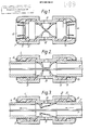
- Figure 1 is a schematic section through a tube connector provided with a gas blocking seal according to a preferred embodiment of the invention;
- Figure 2 shows the embodiment of Figure 1 with a fibre package installed;
- Figure 3 shows the embodiment of Figure 1 during installation of the fibre package;
- Figure 4 shows a modified embodiment during fibre package installation;
- Figure 5 is a schematic section through a duct showing an alternative embodiment of seal according to the invention in an open condition; and
- Figure 6 is a schematic section through a duct showing the seal of Figure 5 in a sealing condition.
- The type of system with which the invention is concerned, and the context in which it is described, is in blown fibre installations. Fibre blowing is the process described in our European patent specification 108590, in which lightweight transmission lines are urged along ducts by the viscous drag of a fluid, usually compressed air. The propellant air is typically at an initial pressure of 3 to 10 bar. The transmission lines typically comprise a bundle of optical fibres encased in a lightweight outer covering, and this is termed a fibre package. Fibre packages may also consist of single fibres or lines, and may include electrical conductors.
- Referring to the drawings, Figure 1 shows a tube connector 1 provided with a flexible tubular liner 2 which constitutes a seal. A respective locking ring 6 is provided at each end of the connector 1, the locking rings each receiving and clamping a respective duct section 7 (see Figs. 2 to 4) along which a fibre package P is subsequently blown. The
duct sections 7 form part of a duct along which fibre package P is to be installed. The ends of the duct extend into the ends of the seal 2, whereby compression ofrims 5 on the ends of the connector 1 serves to seal the outer wall ofduct sections 7 against the inner wall of the connector, thereby preventing escape of the installing propellant, or ingress of pressure from the external environment. - The central portion of the connector 1 is provided with
apertures 8 through which the external ambient pressure is communicated to the outer side of the seal 2. The seal 2 itself is moulded to have a waisted shape, the longitudinal section comprising a series of steps and curves. Alternatively, the seal 2 may have a smooth curve or taper from its ends to the centre. The passageway through the centre of the seal 2 is in the nature of a flattened tube, such that it acts as a blockage in the connector 1 and prevents flow of fluid below a particular pressure e.g. below 2 bar. The tube defined by the seal 2 has a minimum internal diameter which is less than the diameter of the fibre package P, so that, once the fibre package is installed, the central part of the seal presses around the circumference of the fibre package to form a gas-tight seal. - The resilience and/or flexibility of the seal 2 is controlled so that the seal remains in sealing engagement around the installed fibre package P (see Figure 2) when the external pressure is normal atmospheric pressure, and the pressure within the duct is less than 2 bar (this value may be varied for different applications). If the external pressure increases, for example due to flooding on one side of a bulkhead, the seal 2 is pushed more firmly against the fibre package P, and increases the resistance of the seal to opening, so that, if there was a fracture in the
duct section 7 on the high pressure (flooded) side of the seal, the duct would not provide a breach of the bulkhead because the same additional pressure maintains the seal in the closed configuration. - Figure 3 shows how the seal 2 may deform in order to permit installation. Air, or some other propellant, is introduced into the duct at a pressure in excess of that required to deform the seal. Consequently, the seal expands rather like a balloon or inner tube, and the propellant and the fibre package P (which is urged along by the propellant) pass through the opened seal 2, which closes around the package once the introduction of pressurised propellant is discontinued. The seal 2 (see Figure 3) deforms by flexure of the central waisted portion in the direction of flow. In an alternative embodiment (see Figure 4), the central waisted portion of the seal 2 flexes radially outwardly. The geometry of the deformation may be aided or controlled by the provision of selective areas or lines of weakness or stiffening (not shown), along which flexure or resistance to flexure will preferentially occur.
- Figures 5 and 6 shown an alternative embodiment, in which a
duct 11 is provided with aninsert seal 12 which comprises an annular flange portion 12a and abody portion 12b. The flange portion 12a engages between two connecting sections of theduct 11, and is formed as part of theconnector 15 that holds the duct section together. Theconnector 15 is not shown in detail in Figs. 5 and 6, but is similar to the connector 1 of Figs. 1 to 4. Alternatively, theflange portion 12b of theseal 12 is adapted to be held by theconnector 15. Thebody portion 12b is made of a relatively-soft, flexible material such as a synthetic rubber, and may have a variety of configurations. For example, it may be tubular with a bore diameter substantially equal to, or less than, the minimum diameter of the transmission line package P that is to be installed along theduct 11. - The bore of the
tubular body portion 12b may be conical or tapering, with the wider end connected to the flange portion 12a. Alternatively, thetubular body portion 12b may comprise a flat body portion consisting essentially of upper and lower lip portions that press against each other in the undisturbed state. - When at rest, either before or after installation of the transmission line package P along the
duct 11 thebody portion 12b is collapsed inwardly as shown in Figure 6. When the transmission line package P is present thetubular body portion 12b forms a seal around the package P which is sufficiently close-fitting to prevent substantive egress (or low pressure flow) of gas along theduct 11. The elasticity of theseal 12 is such that, from one direction, a relatively high pressure flow of gas, such as 100 psi, will expand the seal sufficiently to enable passage of the package P (see Figure 5). Preferably, theseal 12 expands to lie substantially flat against the sides of theduct 11, thereby presenting a minimum impedance to the passage of the package P during a blowing installation. Once the package P is installed, and the injection of compressed gas into theduct 11 has ceased, thebody portion 12b of theseal 12 collapses back onto the fibre package. - The
seal 12 described above with reference to Figs. 5 and 6 is unidirectional, in that it permits fibre blowing installation in one direction, but would remain resistant to opening in the opposite direction. It is envisaged that, by providing a sufficiently-thin seal, rather like a diaphragm with a central, short-lipped aperture, a seal that will open bidirectionally can be provided, with the lips inverting through the aperture to permit either direction of high pressure flow. - Unidirectionally-opening seals may be made to have high resistance in one direction, so that blown installation can take place only from one direction, thus preventing unauthorised installation from the other direction. This may be particularly useful for maintaining integrity within a building, with it being possible to blow packages outwardly from the building, but preventing access or even high pressure fluid flow along the ducts from outside the building.
- Seal of the type described may be provided at intervals along a route to prevent low pressure leakage of contaminants along the duct. Another application is to provide such a seal in lead-through gland between two airtight chambers, for example in the watertight bulkhead of a sea-going vessel. In this latter application, a seal connection, such as that shown in Figure 2, is preferably provided each side of a bulkhead, so that a leak on either side causes additional sealing by water pressure as previously described.
Claims (5)
Priority Applications (1)
| Application Number | Priority Date | Filing Date | Title |
|---|---|---|---|
| EP95115770A EP0691557B1 (en) | 1988-10-05 | 1989-10-04 | Gas seal |
Applications Claiming Priority (2)
| Application Number | Priority Date | Filing Date | Title |
|---|---|---|---|
| GB888823427A GB8823427D0 (en) | 1988-10-05 | 1988-10-05 | Gas seal |
| GB8823427 | 1988-10-05 |
Related Child Applications (2)
| Application Number | Title | Priority Date | Filing Date |
|---|---|---|---|
| EP95115770A Division EP0691557B1 (en) | 1988-10-05 | 1989-10-04 | Gas seal |
| EP95115770.0 Division-Into | 1989-10-04 |
Publications (2)
| Publication Number | Publication Date |
|---|---|
| EP0363188A1 true EP0363188A1 (en) | 1990-04-11 |
| EP0363188B1 EP0363188B1 (en) | 1996-06-26 |
Family
ID=10644774
Family Applications (2)
| Application Number | Title | Priority Date | Filing Date |
|---|---|---|---|
| EP95115770A Expired - Lifetime EP0691557B1 (en) | 1988-10-05 | 1989-10-04 | Gas seal |
| EP89310176A Expired - Lifetime EP0363188B1 (en) | 1988-10-05 | 1989-10-04 | Gas seal |
Family Applications Before (1)
| Application Number | Title | Priority Date | Filing Date |
|---|---|---|---|
| EP95115770A Expired - Lifetime EP0691557B1 (en) | 1988-10-05 | 1989-10-04 | Gas seal |
Country Status (13)
| Country | Link |
|---|---|
| US (1) | US5138691A (en) |
| EP (2) | EP0691557B1 (en) |
| JP (1) | JPH04500867A (en) |
| AT (1) | ATE139849T1 (en) |
| AU (1) | AU622233B2 (en) |
| CA (1) | CA2000207C (en) |
| DE (2) | DE68929272T2 (en) |
| DK (1) | DK169114B1 (en) |
| ES (1) | ES2088897T3 (en) |
| GB (1) | GB8823427D0 (en) |
| IE (2) | IE73478B1 (en) |
| NZ (1) | NZ230908A (en) |
| WO (1) | WO1990004192A1 (en) |
Cited By (9)
| Publication number | Priority date | Publication date | Assignee | Title |
|---|---|---|---|---|
| EP0410735A3 (en) * | 1989-07-28 | 1991-10-02 | Bicc Public Limited Company | Overhead electric and optical transmission systems |
| EP0691557A2 (en) | 1988-10-05 | 1996-01-10 | BRITISH TELECOMMUNICATIONS public limited company | Gas seal |
| GB2298690A (en) * | 1994-10-10 | 1996-09-11 | David Frederick Hawkins | Connector |
| FR2920887A1 (en) * | 2007-09-07 | 2009-03-13 | Legris Sa | DEVICE FOR CONNECTING END OF GUIDE TUBES AND PROTECTING A CABLE |
| US7644959B2 (en) | 2006-02-10 | 2010-01-12 | John Guest International Limited | Tube couplings for connecting a pair of conduits for carrying a cable |
| FR2946117A1 (en) * | 2010-05-11 | 2010-12-03 | Legris Sas | Device for connecting protection tubes for protecting optical fibers cable of optical transmission circuit, has sealing element arranged in end housing, where element is arranged to be brought into state under effect of axial compression |
| EP2282387A2 (en) | 2009-08-07 | 2011-02-09 | John Guest International Limited | Improvements in or relating to connectors for cable carrying conduits |
| CN103757807A (en) * | 2013-12-31 | 2014-04-30 | 吴江市豪辉布业有限公司 | Yarn guide |
| ITMI20130255A1 (en) * | 2013-02-22 | 2014-08-23 | Prysmian Spa | WATER LOCKING ELEMENT FOR PIPE FOR OPTICAL FIBER BLOWING |
Families Citing this family (5)
| Publication number | Priority date | Publication date | Assignee | Title |
|---|---|---|---|---|
| US5426715A (en) * | 1993-07-23 | 1995-06-20 | Raychem Corporation | Oval port seal and method used for an optical fiber cable closure |
| GB0118963D0 (en) * | 2001-08-03 | 2001-09-26 | Kymata Ltd | An optical waveguide feedthrough |
| DE10158863A1 (en) | 2001-11-30 | 2003-06-12 | Ccs Technology Inc | Optical fiber cables |
| GB2423195B8 (en) * | 2005-02-10 | 2007-11-20 | Brand Rex Ltd | Improvements in or relating to connectors |
| KR100856658B1 (en) | 2006-11-08 | 2008-09-04 | 주식회사 케이티 | Optical fiber laying method and device using vacuum pump |
Citations (5)
| Publication number | Priority date | Publication date | Assignee | Title |
|---|---|---|---|---|
| DE1201139B (en) * | 1955-09-27 | 1965-09-16 | Renault | Valve made of elastic material with variable flow cross-section |
| FR2136499A7 (en) * | 1971-04-28 | 1972-12-22 | Junkers & Co | |
| GB2122367A (en) * | 1982-05-06 | 1984-01-11 | Standard Telephones Cables Ltd | Laying cables |
| EP0108590A1 (en) * | 1982-11-08 | 1984-05-16 | BRITISH TELECOMMUNICATIONS public limited company | Optical fibre transmission lines |
| EP0204065A1 (en) * | 1985-05-16 | 1986-12-10 | American Meter Company | Gas flow calibration device including a critical flow device |
Family Cites Families (7)
| Publication number | Priority date | Publication date | Assignee | Title |
|---|---|---|---|---|
| US3689031A (en) * | 1971-01-14 | 1972-09-05 | Jet Line Products Inc | Apparatus for installing pull lines in conduits |
| US4756595A (en) * | 1986-04-21 | 1988-07-12 | Honeywell Inc. | Optical fiber connector for high pressure environments |
| ZA88533B (en) * | 1987-01-29 | 1988-12-28 | Commw Ind Gases | Gas powered line feeder gun |
| GB8706803D0 (en) * | 1987-03-23 | 1987-04-29 | British Telecomm | Optical fibre installation |
| GB8717715D0 (en) * | 1987-07-27 | 1987-09-03 | Bicc Plc | Optical fibre transmission lines |
| GB8823427D0 (en) * | 1988-10-05 | 1988-11-09 | British Telecomm | Gas seal |
| JP2585823B2 (en) * | 1989-02-08 | 1997-02-26 | 住友電気工業株式会社 | Optical fiber unit |
-
1988
- 1988-10-05 GB GB888823427A patent/GB8823427D0/en active Pending
-
1989
- 1989-10-04 EP EP95115770A patent/EP0691557B1/en not_active Expired - Lifetime
- 1989-10-04 IE IE317089A patent/IE73478B1/en not_active IP Right Cessation
- 1989-10-04 US US07/681,538 patent/US5138691A/en not_active Expired - Lifetime
- 1989-10-04 DE DE68929272T patent/DE68929272T2/en not_active Expired - Fee Related
- 1989-10-04 DE DE68926730T patent/DE68926730T2/en not_active Expired - Fee Related
- 1989-10-04 AT AT89310176T patent/ATE139849T1/en not_active IP Right Cessation
- 1989-10-04 JP JP1510510A patent/JPH04500867A/en active Pending
- 1989-10-04 ES ES89310176T patent/ES2088897T3/en not_active Expired - Lifetime
- 1989-10-04 AU AU44020/89A patent/AU622233B2/en not_active Ceased
- 1989-10-04 EP EP89310176A patent/EP0363188B1/en not_active Expired - Lifetime
- 1989-10-04 IE IE960885A patent/IE82137B1/en not_active IP Right Cessation
- 1989-10-04 WO PCT/GB1989/001176 patent/WO1990004192A1/en not_active Ceased
- 1989-10-05 NZ NZ230908A patent/NZ230908A/en unknown
- 1989-10-05 CA CA002000207A patent/CA2000207C/en not_active Expired - Lifetime
-
1991
- 1991-04-04 DK DK060091A patent/DK169114B1/en not_active IP Right Cessation
Patent Citations (5)
| Publication number | Priority date | Publication date | Assignee | Title |
|---|---|---|---|---|
| DE1201139B (en) * | 1955-09-27 | 1965-09-16 | Renault | Valve made of elastic material with variable flow cross-section |
| FR2136499A7 (en) * | 1971-04-28 | 1972-12-22 | Junkers & Co | |
| GB2122367A (en) * | 1982-05-06 | 1984-01-11 | Standard Telephones Cables Ltd | Laying cables |
| EP0108590A1 (en) * | 1982-11-08 | 1984-05-16 | BRITISH TELECOMMUNICATIONS public limited company | Optical fibre transmission lines |
| EP0204065A1 (en) * | 1985-05-16 | 1986-12-10 | American Meter Company | Gas flow calibration device including a critical flow device |
Cited By (21)
| Publication number | Priority date | Publication date | Assignee | Title |
|---|---|---|---|---|
| EP0691557A2 (en) | 1988-10-05 | 1996-01-10 | BRITISH TELECOMMUNICATIONS public limited company | Gas seal |
| EP0691557A3 (en) * | 1988-10-05 | 1996-04-24 | British Telecomm | Gas seal |
| EP0410735A3 (en) * | 1989-07-28 | 1991-10-02 | Bicc Public Limited Company | Overhead electric and optical transmission systems |
| GB2298690A (en) * | 1994-10-10 | 1996-09-11 | David Frederick Hawkins | Connector |
| US5933556A (en) * | 1994-10-10 | 1999-08-03 | Hawkins; David F | Connector |
| EP0786062B1 (en) * | 1994-10-10 | 2000-02-02 | David Frederick Hawkins | Connector |
| US7644959B2 (en) | 2006-02-10 | 2010-01-12 | John Guest International Limited | Tube couplings for connecting a pair of conduits for carrying a cable |
| US7887242B2 (en) | 2007-09-07 | 2011-02-15 | Legris Sas | Coupling for cable carrier tubes |
| FR2920887A1 (en) * | 2007-09-07 | 2009-03-13 | Legris Sa | DEVICE FOR CONNECTING END OF GUIDE TUBES AND PROTECTING A CABLE |
| WO2009060148A1 (en) * | 2007-09-07 | 2009-05-14 | Legris Sa | Device for connecting the ends of cable guidance and protection tubes |
| CN101796445B (en) * | 2007-09-07 | 2012-09-05 | 勒格里联合股份公司 | device for joining together the ends of tubes used to guide and protect optical cables |
| EP2282387A2 (en) | 2009-08-07 | 2011-02-09 | John Guest International Limited | Improvements in or relating to connectors for cable carrying conduits |
| US8444325B2 (en) | 2009-08-07 | 2013-05-21 | John Guest International Limited | Connectors for cable carrying conduits |
| WO2011141517A1 (en) * | 2010-05-11 | 2011-11-17 | Parker Hannifin France Sas | Device for connecting protective tubes of a fiber-optic cable, section of an optical transmission circuit comprising such a device and sealing element for such a device |
| FR2960039A1 (en) * | 2010-05-11 | 2011-11-18 | Legris Sas | DEVICE FOR CONNECTING PROTECTION TUBES OF AN OPTICAL FIBER CABLE, TRONCON OF AN OPTICAL TRANSMISSION CIRCUIT COMPRISING SUCH A DEVICE AND SEALING ELEMENT FOR SUCH A DEVICE |
| FR2946117A1 (en) * | 2010-05-11 | 2010-12-03 | Legris Sas | Device for connecting protection tubes for protecting optical fibers cable of optical transmission circuit, has sealing element arranged in end housing, where element is arranged to be brought into state under effect of axial compression |
| CN102985863A (en) * | 2010-05-11 | 2013-03-20 | 帕克汉尼芬制造业法国联合股份公司 | Device for connecting protective tubes of a fiber-optic cable, section of an optical transmission circuit comprising such a device and sealing element for such a device |
| US9341803B2 (en) | 2010-05-11 | 2016-05-17 | Parker Hannifin Manufacturing France Sas | Device for connecting together tubes for protecting an optical fiber cable, a segment of an optical transmission circuit including such a device, and a sealing element for such a device |
| ITMI20130255A1 (en) * | 2013-02-22 | 2014-08-23 | Prysmian Spa | WATER LOCKING ELEMENT FOR PIPE FOR OPTICAL FIBER BLOWING |
| EP2770358A1 (en) * | 2013-02-22 | 2014-08-27 | Prysmian S.p.A. | Water-block element for fiber-optic blown tube |
| CN103757807A (en) * | 2013-12-31 | 2014-04-30 | 吴江市豪辉布业有限公司 | Yarn guide |
Also Published As
| Publication number | Publication date |
|---|---|
| JPH04500867A (en) | 1992-02-13 |
| AU622233B2 (en) | 1992-04-02 |
| WO1990004192A1 (en) | 1990-04-19 |
| EP0691557A2 (en) | 1996-01-10 |
| EP0691557B1 (en) | 2000-12-13 |
| DK60091A (en) | 1991-04-04 |
| CA2000207C (en) | 2001-03-13 |
| DE68926730D1 (en) | 1996-08-01 |
| US5138691A (en) | 1992-08-11 |
| IE82137B1 (en) | 2002-01-29 |
| DE68929272T2 (en) | 2001-07-19 |
| DK169114B1 (en) | 1994-08-15 |
| DE68926730T2 (en) | 1996-11-07 |
| DK60091D0 (en) | 1991-04-04 |
| ATE139849T1 (en) | 1996-07-15 |
| EP0363188B1 (en) | 1996-06-26 |
| IE73478B1 (en) | 1997-06-04 |
| DE68929272D1 (en) | 2001-01-18 |
| EP0691557A3 (en) | 1996-04-24 |
| IE893170L (en) | 1990-04-05 |
| GB8823427D0 (en) | 1988-11-09 |
| NZ230908A (en) | 1993-02-25 |
| CA2000207A1 (en) | 1990-04-05 |
| AU4402089A (en) | 1990-05-01 |
| ES2088897T3 (en) | 1996-10-01 |
| IE960885L (en) | 1990-04-05 |
Similar Documents
| Publication | Publication Date | Title |
|---|---|---|
| US5138691A (en) | Gas seal | |
| US5366260A (en) | Plastic pipe coupler | |
| US4426095A (en) | Flexible seal | |
| US5360945A (en) | Cable seal | |
| KR100249293B1 (en) | Peripheral Seal Member and Method | |
| AU673274B2 (en) | Access plug flange | |
| EP0543103B1 (en) | A sealing device | |
| US6256948B1 (en) | Fire-resistant passage for lines | |
| EP0278544B1 (en) | Sealing device | |
| BG99474A (en) | Seal | |
| CN101218728A (en) | Sealing element for an access port | |
| US5792991A (en) | Environmental seal | |
| US20040124589A1 (en) | Seal device for tubular member | |
| US6050613A (en) | Combined plastic pipe coupler and end plug | |
| AU657812B2 (en) | A cable sleeve composed of a longitudinally-divided housing | |
| HK112197A (en) | Gas seal | |
| US4255614A (en) | Method and apparatus for enclosing a cable splice | |
| US5859388A (en) | Splice closure | |
| US4619291A (en) | Duct for cable | |
| KR960010572Y1 (en) | Waterproof caps on tubes for communication and power cable wiring | |
| KR860001926B1 (en) | Multi-Film Flexible Film Index | |
| US5782498A (en) | Sealing flange, in particular for internal lining of pipes | |
| US6113067A (en) | Self-sealing pressure valve assembly | |
| GB2423195A (en) | Sealed conduit connectors. | |
| US20040069369A1 (en) | Sealable lead-through system |
Legal Events
| Date | Code | Title | Description |
|---|---|---|---|
| PUAI | Public reference made under article 153(3) epc to a published international application that has entered the european phase |
Free format text: ORIGINAL CODE: 0009012 |
|
| AK | Designated contracting states |
Kind code of ref document: A1 Designated state(s): AT BE CH DE ES FR GB GR IT LI LU NL SE |
|
| 17P | Request for examination filed |
Effective date: 19900612 |
|
| 17Q | First examination report despatched |
Effective date: 19920311 |
|
| GRAH | Despatch of communication of intention to grant a patent |
Free format text: ORIGINAL CODE: EPIDOS IGRA |
|
| GRAA | (expected) grant |
Free format text: ORIGINAL CODE: 0009210 |
|
| AK | Designated contracting states |
Kind code of ref document: B1 Designated state(s): AT BE CH DE ES FR GB GR IT LI LU NL SE |
|
| PG25 | Lapsed in a contracting state [announced via postgrant information from national office to epo] |
Ref country code: AT Effective date: 19960626 Ref country code: GR Free format text: LAPSE BECAUSE OF FAILURE TO SUBMIT A TRANSLATION OF THE DESCRIPTION OR TO PAY THE FEE WITHIN THE PRESCRIBED TIME-LIMIT Effective date: 19960626 |
|
| REF | Corresponds to: |
Ref document number: 139849 Country of ref document: AT Date of ref document: 19960715 Kind code of ref document: T |
|
| XX | Miscellaneous (additional remarks) |
Free format text: TEILANMELDUNG 95115372.5 EINGEREICHT AM 29/09/95. |
|
| ITF | It: translation for a ep patent filed | ||
| REF | Corresponds to: |
Ref document number: 68926730 Country of ref document: DE Date of ref document: 19960801 |
|
| GRAH | Despatch of communication of intention to grant a patent |
Free format text: ORIGINAL CODE: EPIDOS IGRA |
|
| REG | Reference to a national code |
Ref country code: ES Ref legal event code: FG2A Ref document number: 2088897 Country of ref document: ES Kind code of ref document: T3 |
|
| ET | Fr: translation filed | ||
| ET | Fr: translation filed | ||
| PG25 | Lapsed in a contracting state [announced via postgrant information from national office to epo] |
Ref country code: LU Free format text: LAPSE BECAUSE OF NON-PAYMENT OF DUE FEES Effective date: 19961031 |
|
| REG | Reference to a national code |
Ref country code: ES Ref legal event code: FG2A Ref document number: 2088897 Country of ref document: ES Kind code of ref document: T3 |
|
| PLBE | No opposition filed within time limit |
Free format text: ORIGINAL CODE: 0009261 |
|
| STAA | Information on the status of an ep patent application or granted ep patent |
Free format text: STATUS: NO OPPOSITION FILED WITHIN TIME LIMIT |
|
| 26N | No opposition filed | ||
| PGFP | Annual fee paid to national office [announced via postgrant information from national office to epo] |
Ref country code: BE Payment date: 19970916 Year of fee payment: 9 |
|
| PGFP | Annual fee paid to national office [announced via postgrant information from national office to epo] |
Ref country code: SE Payment date: 19970918 Year of fee payment: 9 |
|
| PGFP | Annual fee paid to national office [announced via postgrant information from national office to epo] |
Ref country code: ES Payment date: 19971008 Year of fee payment: 9 |
|
| PG25 | Lapsed in a contracting state [announced via postgrant information from national office to epo] |
Ref country code: ES Free format text: LAPSE BECAUSE OF THE APPLICANT RENOUNCES Effective date: 19981005 Ref country code: SE Free format text: LAPSE BECAUSE OF NON-PAYMENT OF DUE FEES Effective date: 19981005 |
|
| PG25 | Lapsed in a contracting state [announced via postgrant information from national office to epo] |
Ref country code: BE Free format text: LAPSE BECAUSE OF NON-PAYMENT OF DUE FEES Effective date: 19981031 |
|
| BERE | Be: lapsed |
Owner name: BRITISH TELECOMMUNICATIONS P.L.C. Effective date: 19981031 |
|
| EUG | Se: european patent has lapsed |
Ref document number: 89310176.6 |
|
| REG | Reference to a national code |
Ref country code: ES Ref legal event code: FD2A Effective date: 20001009 |
|
| PGFP | Annual fee paid to national office [announced via postgrant information from national office to epo] |
Ref country code: CH Payment date: 20010919 Year of fee payment: 13 |
|
| REG | Reference to a national code |
Ref country code: GB Ref legal event code: IF02 |
|
| PG25 | Lapsed in a contracting state [announced via postgrant information from national office to epo] |
Ref country code: LI Free format text: LAPSE BECAUSE OF NON-PAYMENT OF DUE FEES Effective date: 20021031 Ref country code: CH Free format text: LAPSE BECAUSE OF NON-PAYMENT OF DUE FEES Effective date: 20021031 |
|
| REG | Reference to a national code |
Ref country code: CH Ref legal event code: PL |
|
| PG25 | Lapsed in a contracting state [announced via postgrant information from national office to epo] |
Ref country code: IT Free format text: LAPSE BECAUSE OF NON-PAYMENT OF DUE FEES;WARNING: LAPSES OF ITALIAN PATENTS WITH EFFECTIVE DATE BEFORE 2007 MAY HAVE OCCURRED AT ANY TIME BEFORE 2007. THE CORRECT EFFECTIVE DATE MAY BE DIFFERENT FROM THE ONE RECORDED. Effective date: 20051004 |
|
| PGFP | Annual fee paid to national office [announced via postgrant information from national office to epo] |
Ref country code: GB Payment date: 20070921 Year of fee payment: 19 |
|
| PGFP | Annual fee paid to national office [announced via postgrant information from national office to epo] |
Ref country code: NL Payment date: 20070913 Year of fee payment: 19 Ref country code: DE Payment date: 20070921 Year of fee payment: 19 |
|
| PGFP | Annual fee paid to national office [announced via postgrant information from national office to epo] |
Ref country code: FR Payment date: 20070912 Year of fee payment: 19 |
|
| GBPC | Gb: european patent ceased through non-payment of renewal fee |
Effective date: 20081004 |
|
| NLV4 | Nl: lapsed or anulled due to non-payment of the annual fee |
Effective date: 20090501 |
|
| REG | Reference to a national code |
Ref country code: FR Ref legal event code: ST Effective date: 20090630 |
|
| PG25 | Lapsed in a contracting state [announced via postgrant information from national office to epo] |
Ref country code: NL Free format text: LAPSE BECAUSE OF NON-PAYMENT OF DUE FEES Effective date: 20090501 |
|
| PG25 | Lapsed in a contracting state [announced via postgrant information from national office to epo] |
Ref country code: DE Free format text: LAPSE BECAUSE OF NON-PAYMENT OF DUE FEES Effective date: 20090501 |
|
| PG25 | Lapsed in a contracting state [announced via postgrant information from national office to epo] |
Ref country code: FR Free format text: LAPSE BECAUSE OF NON-PAYMENT OF DUE FEES Effective date: 20081031 |
|
| PG25 | Lapsed in a contracting state [announced via postgrant information from national office to epo] |
Ref country code: GB Free format text: LAPSE BECAUSE OF NON-PAYMENT OF DUE FEES Effective date: 20081004 |