EP1818584A2 - Solenoid valve - Google Patents
Solenoid valve Download PDFInfo
- Publication number
- EP1818584A2 EP1818584A2 EP07101405A EP07101405A EP1818584A2 EP 1818584 A2 EP1818584 A2 EP 1818584A2 EP 07101405 A EP07101405 A EP 07101405A EP 07101405 A EP07101405 A EP 07101405A EP 1818584 A2 EP1818584 A2 EP 1818584A2
- Authority
- EP
- European Patent Office
- Prior art keywords
- coil spring
- stator core
- valve
- coil
- receiving bore
- Prior art date
- Legal status (The legal status is an assumption and is not a legal conclusion. Google has not performed a legal analysis and makes no representation as to the accuracy of the status listed.)
- Granted
Links
- 230000002093 peripheral effect Effects 0.000 claims abstract description 21
- 101150087322 DCPS gene Proteins 0.000 claims description 4
- 239000000696 magnetic material Substances 0.000 claims description 2
- 239000000446 fuel Substances 0.000 description 18
- 238000002347 injection Methods 0.000 description 12
- 239000007924 injection Substances 0.000 description 12
- 239000002828 fuel tank Substances 0.000 description 5
- 238000002485 combustion reaction Methods 0.000 description 3
- 239000000428 dust Substances 0.000 description 3
- 230000000881 depressing effect Effects 0.000 description 2
- 230000002452 interceptive effect Effects 0.000 description 2
- 238000002788 crimping Methods 0.000 description 1
- 230000003247 decreasing effect Effects 0.000 description 1
- 230000000593 degrading effect Effects 0.000 description 1
- 238000011156 evaluation Methods 0.000 description 1
- 238000002474 experimental method Methods 0.000 description 1
- ZZUFCTLCJUWOSV-UHFFFAOYSA-N furosemide Chemical compound C1=C(Cl)C(S(=O)(=O)N)=CC(C(O)=O)=C1NCC1=CC=CO1 ZZUFCTLCJUWOSV-UHFFFAOYSA-N 0.000 description 1
- 239000002184 metal Substances 0.000 description 1
- 238000000034 method Methods 0.000 description 1
- 238000012986 modification Methods 0.000 description 1
- 230000004048 modification Effects 0.000 description 1
- 230000008569 process Effects 0.000 description 1
- 230000004044 response Effects 0.000 description 1
Images

Classifications
-
- F—MECHANICAL ENGINEERING; LIGHTING; HEATING; WEAPONS; BLASTING
- F16—ENGINEERING ELEMENTS AND UNITS; GENERAL MEASURES FOR PRODUCING AND MAINTAINING EFFECTIVE FUNCTIONING OF MACHINES OR INSTALLATIONS; THERMAL INSULATION IN GENERAL
- F16K—VALVES; TAPS; COCKS; ACTUATING-FLOATS; DEVICES FOR VENTING OR AERATING
- F16K31/00—Actuating devices; Operating means; Releasing devices
- F16K31/02—Actuating devices; Operating means; Releasing devices electric; magnetic
- F16K31/06—Actuating devices; Operating means; Releasing devices electric; magnetic using a magnet, e.g. diaphragm valves, cutting off by means of a liquid
- F16K31/0644—One-way valve
- F16K31/0655—Lift valves
- F16K31/0658—Armature and valve member being one single element
-
- F—MECHANICAL ENGINEERING; LIGHTING; HEATING; WEAPONS; BLASTING
- F16—ENGINEERING ELEMENTS AND UNITS; GENERAL MEASURES FOR PRODUCING AND MAINTAINING EFFECTIVE FUNCTIONING OF MACHINES OR INSTALLATIONS; THERMAL INSULATION IN GENERAL
- F16K—VALVES; TAPS; COCKS; ACTUATING-FLOATS; DEVICES FOR VENTING OR AERATING
- F16K31/00—Actuating devices; Operating means; Releasing devices
- F16K31/02—Actuating devices; Operating means; Releasing devices electric; magnetic
- F16K31/06—Actuating devices; Operating means; Releasing devices electric; magnetic using a magnet, e.g. diaphragm valves, cutting off by means of a liquid
- F16K31/0686—Braking, pressure equilibration, shock absorbing
- F16K31/0689—Braking of the valve element
-
- G—PHYSICS
- G05—CONTROLLING; REGULATING
- G05D—SYSTEMS FOR CONTROLLING OR REGULATING NON-ELECTRIC VARIABLES
- G05D16/00—Control of fluid pressure
- G05D16/20—Control of fluid pressure characterised by the use of electric means
- G05D16/2006—Control of fluid pressure characterised by the use of electric means with direct action of electric energy on controlling means
- G05D16/2013—Control of fluid pressure characterised by the use of electric means with direct action of electric energy on controlling means using throttling means as controlling means
- G05D16/2022—Control of fluid pressure characterised by the use of electric means with direct action of electric energy on controlling means using throttling means as controlling means actuated by a proportional solenoid
Definitions
- the present invention relates to a solenoid valve, in which a valve member is attracted by a magnetic attractive force in one direction and is biased in an opposite direction opposite from the one direction by a coil spring.
- a valve member In a conventional valve, a valve member is attracted toward a stator core when a coil is energized, and the valve member is biased in a non-attracted direction opposite from the stator core by a coil spring. Also, the coil spring is received in a receiving bore formed in the stator core (see e.g., JP-A-2001-182638 ).
- the present invention is made in view of the above disadvantages. Thus, it is an objective of the present invention to limit a sliding fault of a valve member due to a dust of wear.
- a solenoid valve which includes a coil, a stator core, a valve member, a coil spring, and a stopper.
- the coil provides a magnetic field when the coil is energized.
- the stator core includes a receiving bore, wherein the stator core generates a magnetic attractive force when the coil is energized.
- the valve member is attracted toward the stator core due to the magnetic attractive force generated by the stator core.
- the coil spring is received in the receiving bore of the stator core, wherein the coil spring biases the valve member in an opposite direction opposite from the stator core.
- the stopper positions the coil spring such that an outer peripheral surface of the coil spring is separated from an inner peripheral surface of the receiving bore.
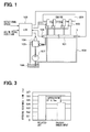
- FIG. 1 is a schematic view of a common rail fuel injection system, which includes a solenoid valve according to the first embodiment of the present invention.
- the fuel injection system of the first embodiment includes an accumulator 101, a diesel engine 201, multiple injection valves 102, and an electronic control unit (ECU) 103.
- the accumulator 101 can accumulate high-pressure fuel.
- Each of the injection valves 102 is provided to a corresponding one of cylinders of the diesel engine 201, and is connected with the accumulator 101.
- the ECU 103 which serves as control means, controls valve open timing and a valve open period of the injection valve 102.
- the ECU 103 includes a microcomputer having a CPU, a ROM, and a RAM (not shown), and executes in order various processes stored in the microcomputer.
- the ECU 103 receives information, such as an engine rotational speed and a depressing amount (a pedal position) of an accelerator pedal (not shown). Then, the ECU 103 controls the injection valves 102, a pump amount control valve 104, and the solenoid valve 1 based on the information.
- the high-pressure fuel which is pumped by a fuel pump 105, is accumulated at a predetermined pressure that corresponds to fuel injection pressure.
- a known variable delivery high-pressure pump serves as the fuel pump 105 and the fuel pump 105 compresses low-pressure fuel at high pressure.
- the low-pressure fuel is supplied from a fuel tank 106, which serves as a low-pressure portion, through a feed pump 107.
- the ECU 103 Based on signals supplied from a pressure sensor 108, which is provided to the accumulator 101, the ECU 103 drives the pump amount control valve 104 to control a pump amount such that the injection pressure becomes a predetermined value, which is determined based on a load and the rotational speed.
- the pump amount control valve 104 is provided to the fuel pump 105.
- the accumulator 101 is connected with the fuel tank 106 through a low-pressure passage 109, which constitutes a discharge passage.
- the solenoid valve 1 is located between the low-pressure passage 109 and the accumulator 101.
- the ECU 103 controls the solenoid valve 1 based on an operational state of the internal combustion engine 201.
- the high-pressure fuel in the accumulator 101 is returned to the fuel tank 106 through the low-pressure passage 109 when the solenoid valve 1 is opened.
- the pressure inside the accumulator 101 can be reduced to a target value.
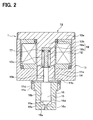
- FIG. 2 is a sectional view showing a specific structure of the solenoid valve 1, and as shown in FIG. 2, the solenoid valve 1 includes a solenoid housing 11, which is a cylinder with a bottom. Specifically, one end of the solenoid housing 11 is open, and the solenoid housing 11 has a bottom portion 11a at the other end thereof.
- the solenoid housing 11 receives a tubular coil 12, which forms a magnetic field when the coil 12 is energized.
- An opening portion of the solenoid housing 11 is blocked by the stator core 13.
- the stator core 13 includes a discoid cap portion 13a and a column portion 13b.
- the cap portion 13a covers the opening portion of the solenoid housing 11, and the column portion 13b extends from a radial center portion of the cap portion 13a toward a space inside a tube of the coil 12.
- the bottom portion 11a of the solenoid housing 11 includes a through hole 11b at a radial center portion of the bottom portion 11a, and the through hole 11b communicates with the space inside the tube of the coil 12b.
- the through hole 11b receives an armature 14 therein.
- the solenoid housing 11, the stator core 13, and the armature 14 are all made of magnetic metal, and forms a magnetic circuit. Also, it is designed that when the coil 12 is energized, the armature 14 is attracted toward the stator core 13.
- a valve housing 16, which supports a circular column valve body 15, is provided at an outer side of the bottom portion 11a of the solenoid housing 11.
- the valve housing 16 has an opening end on one end and a bottom portion 16a on another end such that the valve housing 16 has a cylindrical shape with a bottom.
- the valve housing 16 includes a sliding bore 16b at a radial center portion of the valve housing 16. The sliding bore 16b extends in a longitudinal direction and slidably receives the valve body 15 therein.
- a cylindrical tubular portion 11c is provided at an outer side of the bottom portion 11a of the solenoid housing 11.
- the valve housing 16 is fixed to the solenoid housing 11 by crimping an end portion of the tubular portion 11c.
- a male thread 11d is provided at an outer periphery of the tubular portion 11c.
- the bottom portion 16a of the valve housing 16 includes a first discharge passage 16c at a radial center portion of the bottom portion 16a.
- the first discharge passage 16c longitudinally extends through the bottom portion 16a and communicates with the accumulator 101.
- a cylindrical portion of the valve housing 16 includes a second discharge passage 16d, which radially extends through the cylindrical portion, and the second discharge passage 16d communicates with the low-pressure passage 109 (see FIG. 1).
- a tapered valve seat 16e is formed coaxially with the first discharge passage 16c at a position of the bottom portion 16a of the valve housing 16. Here, the position faces with the valve body 15.
- a tapered seat surface 15a is formed at a position of the valve body 15, the position facing the valve seat 16e.
- the first discharge passage 16c is disconnected from and connected with the second discharge passage 16d, respectively.
- a circular column rod 15b is integrally formed on an opposite side of the valve body 15 opposite from the seat surface 15a, and the circular column rod 15b extends into the through hole 11b of the solenoid housing 11.
- the armature 14 is press-fitted and fixed at an outer periphery of the rod 15b.
- the armature 14 and the valve body 15 constitute a valve member of the present invention.
- a circular column receiving bore 13c is formed at the column portion 13b of the stator core 13 at a radial center portion thereof.
- the receiving bore 13c extends in the longitudinal direction of the stator core 13, and an end portion on a valve body 15 side of the receiving bore 13c opens.
- the receiving bore 13c receives a coil spring 17 and a stopper 18.
- the coil spring 17 biases the armature 14 and the valve body 15 in an opposite direction (non-attracted direction) opposite from the stator core 13.
- the stopper 18 positions the coil spring 17.
- the stopper 18 includes a large diameter portion 18a (first portion) and a small diameter portion 18b (second portion).
- the large diameter portion 18a has a circular column shape and is provided at one side of the stopper 18 closer to a bottom portion (end portion) of the receiving bore 13c.
- the small diameter portion 18b has a circular column shape and extends from a radial center portion the large diameter portion 18a toward the valve body 15.
- the small diameter portion 18b has a diameter (cross sectional area) smaller than that of the large diameter portion 18a.
- the coil spring 17 is provided at an outer periphery of the small diameter portion 18b, and the small diameter portion 18b limits a movable range of the coil spring 17 in a radial direction. Therefore, the outer peripheral surface of the coil spring 17 is limited from being in contact with an inner peripheral surface of the receiving bore 13c. That is, the outer peripheral surface of the coil spring 17 is separated from the inner peripheral surface of the receiving bore 13c.
- the outer peripheral surface of the coil spring 17 means a radially outer surface of the coil spring 17.
- One longitudinal end of the coil spring 17 is supported by the large diameter portion 18a, and the other longitudinal end of the coil spring 17 is supported by the armature 14 or by the rod 15b of the valve body 15.
- the rod 15b of the valve body 15 contacts an end portion of the small diameter portion 18b. Therefore, the movable range of the armature 14 and the valve body 15 toward the stator core 13 is limited.
- the coil 12 of the solenoid valve 1 is deenergized except for a case where the rotational speed of the internal combustion engine 201 is decreased.
- the coil spring 17 biases the armature 14 and the valve body 15 in a valve closing direction such that the seat surface 15a of the valve body 15 engages with the valve seat 16e of the valve housing 16.
- the first discharge passage 16c is disconnected from the second discharge passage 16d.
- the ECU 103 controls the solenoid valve 1 such that the solenoid valve 1 is opened. Then, the high-pressure fuel in the accumulator 101 is discharged into the fuel tank 106, and therefore, the pressure in the accumulator 101 is quickly reduced to the target value.
- the coil 12 of the solenoid valve 1 is energized such that the armature 14 is attracted toward the column portion 13b of the stator core 13 by the magnetic attractive force of the stator core 13.
- the valve body 15, which is integrated with the armature 14 is displaced toward the column portion 13b.
- the seat surface 15a of the valve body 15 is disengaged from the valve seat 16e of the valve housing 16 such that the first discharge passage 16c is communicated with the second discharge passage 16d.
- the high-pressure fuel in the accumulator 101 is discharged into the fuel tank 106 through the first and second discharge passages 16c, 16d and the low-pressure passage 109.
- the stopper 18 positions the coil spring 17 such that the outer peripheral surface of the coil spring 17 is limited from contacting the inner peripheral surface of the receiving bore 13c.
- the dust due to the friction between the coil spring 17 and the stator core 13 is not generated.
- the sliding fault of the valve body 15 due to the dust can be limited.
- the responsibility of the solenoid valve 1 of the present invention is improved by 0.2 ms compared with the conventional solenoid valve when the coil 12 is energized (i.e., when the valve is opened) as shown in FIG. 3.
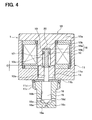
- FIG. 4 is a sectional view of a solenoid valve according to the second embodiment of the present invention. Similar or equivalent components of the present embodiment similar to those of the first embodiment are denoted by the same numerals, and the explanation thereof will be omitted.
- a first shim 19 is provided between the one longitudinal end of the coil spring 17 and the large diameter portion 18a of the stopper 18 such that a set load (applied load) can be adjustable.
- a second shim 20 is provided between the bottom portion of the receiving bore 13c of the stator core 13 and the large diameter portion 18a of the stopper 18 such that an air gap G of the coil spring 17 (e.g., an air gap G between the armature 14 and an end face of the column portion 13b of the stator core 13) can be adjustable without changing the set load.
- an air gap G of the coil spring 17 e.g., an air gap G between the armature 14 and an end face of the column portion 13b of the stator core 13
- the second shim 20 an air gap adjusting shim for adjusting the air gap G
- the first shim 19 a coil spring set load adjusting shim for adjusting the set load applied to the coil spring 17
- FIG. 5 is a sectional view showing a main portion of a solenoid valve according to the third embodiment of the present invention. Similar or equivalent components of the present embodiment similar to those of the first embodiment are denoted by the same numerals, and the explanation thereof will be omitted.
- Dsc - Dcs1 > (Dsc - Dst1) + (Dcs2 - Dst2) is satisfied in a condition where the receiving bore 13c has an inner diameter of Dsc, the large diameter portion 18a has an outer diameter of Dst1, the small diameter portion 18b has an outer diameter of Dst2, the coil spring 17 has an outer diameter of Dcs1, and the coil spring 17 has an inner diameter of Dcs2.
- the outer peripheral surface of the coil spring 17 is reliably limited from interfering with the inner peripheral surface of the receiving bore 13c.
- FIG. 6 is a sectional view showing a main portion of a solenoid valve according to the fourth embodiment of the present invention. Similar or equivalent components of the present embodiment similar to those of the first embodiment are denoted by the same numerals, and the explanation thereof will be omitted.
- a tapered relief portion 18c (narrowing portion), a cross sectional area of which becomes smaller toward the armature 14, is formed at an armature 14 side of the small diameter portion 18b.
- the relief portion 18c may have a frustum shape.
- a solenoid valve includes a coil (12), a stator core (13), a valve member (14, 15), a coil spring (17), and a stopper (18).
- the coil (12) provides a magnetic field when the coil (12) is energized.
- the stator core (13) includes a receiving bore (13c), wherein the stator core (13) generates a magnetic attractive force when the coil (12) is energized.
- the valve member (14, 15) is attracted toward the stator core (13) due to the magnetic attractive force generated by the stator core (13).
- the coil spring (17) is received in the receiving bore (13c) of the stator core (13), wherein the coil spring (17) biases the valve member (14, 15) in an opposite direction opposite from the stator core (13).
- the stopper (18) positions the coil spring (17) such that an outer peripheral surface of the coil spring (17) is separated from an inner peripheral surface of the receiving bore (13c).
Landscapes
- Engineering & Computer Science (AREA)
- General Engineering & Computer Science (AREA)
- Physics & Mathematics (AREA)
- Mechanical Engineering (AREA)
- Fluid Mechanics (AREA)
- General Physics & Mathematics (AREA)
- Automation & Control Theory (AREA)
- Magnetically Actuated Valves (AREA)
- Fuel-Injection Apparatus (AREA)
Abstract
Description
- The present invention relates to a solenoid valve, in which a valve member is attracted by a magnetic attractive force in one direction and is biased in an opposite direction opposite from the one direction by a coil spring.
- In a conventional valve, a valve member is attracted toward a stator core when a coil is energized, and the valve member is biased in a non-attracted direction opposite from the stator core by a coil spring. Also, the coil spring is received in a receiving bore formed in the stator core (see e.g.,
JP-A-2001-182638 - However, in a solenoid valve disclosed in
JP-A-2001-182638 - The present invention is made in view of the above disadvantages. Thus, it is an objective of the present invention to limit a sliding fault of a valve member due to a dust of wear.
- To achieve the objective of the present invention, there is provided a solenoid valve, which includes a coil, a stator core, a valve member, a coil spring, and a stopper. The coil provides a magnetic field when the coil is energized. The stator core includes a receiving bore, wherein the stator core generates a magnetic attractive force when the coil is energized. The valve member is attracted toward the stator core due to the magnetic attractive force generated by the stator core. The coil spring is received in the receiving bore of the stator core, wherein the coil spring biases the valve member in an opposite direction opposite from the stator core. The stopper positions the coil spring such that an outer peripheral surface of the coil spring is separated from an inner peripheral surface of the receiving bore.
- The invention, together with additional objectives, features and advantages thereof, will be best understood from the following description, the appended claims and the accompanying drawings in which:
- FIG. 1 is a schematic view of a common rail fuel injection system, which includes a solenoid valve according to a first embodiment of the present invention;
- FIG. 2 is a sectional view of the solenoid valve shown in FIG. 1;
- FIG. 3 is a chart showing an evaluation result of a response time for valve opening of the solenoid valve;
- FIG. 4 is a sectional view showing a solenoid valve according to a second embodiment of the present invention;
- FIG. 5 is a sectional view showing a main portion of a solenoid valve according to a third embodiment of the present invention; and
- FIG. 6 is a sectional view showing a main portion of a solenoid valve according to a fourth embodiment of the present invention.
- A first embodiment of the present invention will be described. FIG. 1 is a schematic view of a common rail fuel injection system, which includes a solenoid valve according to the first embodiment of the present invention. As shown in FIG. 1, the fuel injection system of the first embodiment includes an
accumulator 101, adiesel engine 201,multiple injection valves 102, and an electronic control unit (ECU) 103. Theaccumulator 101 can accumulate high-pressure fuel. Each of theinjection valves 102 is provided to a corresponding one of cylinders of thediesel engine 201, and is connected with theaccumulator 101. Thus, the high-pressure fuel accumulated in theaccumulator 101 is injected through eachinjection valve 102 to the corresponding cylinder. The ECU 103, which serves as control means, controls valve open timing and a valve open period of theinjection valve 102. - The ECU 103 includes a microcomputer having a CPU, a ROM, and a RAM (not shown), and executes in order various processes stored in the microcomputer. The ECU 103 receives information, such as an engine rotational speed and a depressing amount (a pedal position) of an accelerator pedal (not shown). Then, the ECU 103 controls the
injection valves 102, a pumpamount control valve 104, and thesolenoid valve 1 based on the information. - In the
accumulator 101, the high-pressure fuel, which is pumped by afuel pump 105, is accumulated at a predetermined pressure that corresponds to fuel injection pressure. A known variable delivery high-pressure pump serves as thefuel pump 105 and thefuel pump 105 compresses low-pressure fuel at high pressure. Here, the low-pressure fuel is supplied from afuel tank 106, which serves as a low-pressure portion, through afeed pump 107. Based on signals supplied from apressure sensor 108, which is provided to theaccumulator 101, the ECU 103 drives the pumpamount control valve 104 to control a pump amount such that the injection pressure becomes a predetermined value, which is determined based on a load and the rotational speed. Here, the pumpamount control valve 104 is provided to thefuel pump 105. - The
accumulator 101 is connected with thefuel tank 106 through a low-pressure passage 109, which constitutes a discharge passage. Thesolenoid valve 1 is located between the low-pressure passage 109 and theaccumulator 101. The ECU 103 controls thesolenoid valve 1 based on an operational state of theinternal combustion engine 201. The high-pressure fuel in theaccumulator 101 is returned to thefuel tank 106 through the low-pressure passage 109 when thesolenoid valve 1 is opened. Thus, the pressure inside theaccumulator 101 can be reduced to a target value. - FIG. 2 is a sectional view showing a specific structure of the
solenoid valve 1, and as shown in FIG. 2, thesolenoid valve 1 includes asolenoid housing 11, which is a cylinder with a bottom. Specifically, one end of thesolenoid housing 11 is open, and thesolenoid housing 11 has abottom portion 11a at the other end thereof. Thesolenoid housing 11 receives atubular coil 12, which forms a magnetic field when thecoil 12 is energized. An opening portion of thesolenoid housing 11 is blocked by thestator core 13. Thestator core 13 includes adiscoid cap portion 13a and acolumn portion 13b. Thecap portion 13a covers the opening portion of thesolenoid housing 11, and thecolumn portion 13b extends from a radial center portion of thecap portion 13a toward a space inside a tube of thecoil 12. - The
bottom portion 11a of thesolenoid housing 11 includes a throughhole 11b at a radial center portion of thebottom portion 11a, and thethrough hole 11b communicates with the space inside the tube of the coil 12b. The throughhole 11b receives anarmature 14 therein. - The solenoid housing 11, the
stator core 13, and thearmature 14 are all made of magnetic metal, and forms a magnetic circuit. Also, it is designed that when thecoil 12 is energized, thearmature 14 is attracted toward thestator core 13. - A
valve housing 16, which supports a circularcolumn valve body 15, is provided at an outer side of thebottom portion 11a of thesolenoid housing 11. Thevalve housing 16 has an opening end on one end and abottom portion 16a on another end such that thevalve housing 16 has a cylindrical shape with a bottom. Also, thevalve housing 16 includes asliding bore 16b at a radial center portion of thevalve housing 16. Thesliding bore 16b extends in a longitudinal direction and slidably receives thevalve body 15 therein. - A cylindrical
tubular portion 11c is provided at an outer side of thebottom portion 11a of thesolenoid housing 11. Thevalve housing 16 is fixed to thesolenoid housing 11 by crimping an end portion of thetubular portion 11c. Also, amale thread 11d is provided at an outer periphery of thetubular portion 11c. Thus, with themale thread 11d, thesolenoid valve 1 is fixed to the accumulator 101 (see FIG. 1). - The
bottom portion 16a of thevalve housing 16 includes afirst discharge passage 16c at a radial center portion of thebottom portion 16a. Thefirst discharge passage 16c longitudinally extends through thebottom portion 16a and communicates with theaccumulator 101. - A cylindrical portion of the
valve housing 16 includes asecond discharge passage 16d, which radially extends through the cylindrical portion, and thesecond discharge passage 16d communicates with the low-pressure passage 109 (see FIG. 1). - A tapered
valve seat 16e is formed coaxially with thefirst discharge passage 16c at a position of thebottom portion 16a of thevalve housing 16. Here, the position faces with thevalve body 15. - A
tapered seat surface 15a is formed at a position of thevalve body 15, the position facing thevalve seat 16e. When theseat surface 15a is engaged with and disengaged from thevalve seat 16e, thefirst discharge passage 16c is disconnected from and connected with thesecond discharge passage 16d, respectively. - A
circular column rod 15b is integrally formed on an opposite side of thevalve body 15 opposite from theseat surface 15a, and thecircular column rod 15b extends into the throughhole 11b of thesolenoid housing 11. Thearmature 14 is press-fitted and fixed at an outer periphery of therod 15b. Here, thearmature 14 and thevalve body 15 constitute a valve member of the present invention. - A circular
column receiving bore 13c is formed at thecolumn portion 13b of thestator core 13 at a radial center portion thereof. The receivingbore 13c extends in the longitudinal direction of thestator core 13, and an end portion on avalve body 15 side of the receivingbore 13c opens. - Also, the receiving
bore 13c receives acoil spring 17 and astopper 18. Here, thecoil spring 17 biases thearmature 14 and thevalve body 15 in an opposite direction (non-attracted direction) opposite from thestator core 13. Also, thestopper 18 positions thecoil spring 17. - The
stopper 18 includes alarge diameter portion 18a (first portion) and asmall diameter portion 18b (second portion). Here, thelarge diameter portion 18a has a circular column shape and is provided at one side of thestopper 18 closer to a bottom portion (end portion) of the receivingbore 13c. Also, thesmall diameter portion 18b has a circular column shape and extends from a radial center portion thelarge diameter portion 18a toward thevalve body 15. Thesmall diameter portion 18b has a diameter (cross sectional area) smaller than that of thelarge diameter portion 18a. - The
coil spring 17 is provided at an outer periphery of thesmall diameter portion 18b, and thesmall diameter portion 18b limits a movable range of thecoil spring 17 in a radial direction. Therefore, the outer peripheral surface of thecoil spring 17 is limited from being in contact with an inner peripheral surface of the receivingbore 13c. That is, the outer peripheral surface of thecoil spring 17 is separated from the inner peripheral surface of the receivingbore 13c. Here, the outer peripheral surface of thecoil spring 17 means a radially outer surface of thecoil spring 17. - One longitudinal end of the
coil spring 17 is supported by thelarge diameter portion 18a, and the other longitudinal end of thecoil spring 17 is supported by thearmature 14 or by therod 15b of thevalve body 15. - Also, when the
armature 14 and thevalve body 15 are attracted toward thestator core 13, therod 15b of thevalve body 15 contacts an end portion of thesmall diameter portion 18b. Therefore, the movable range of thearmature 14 and thevalve body 15 toward thestator core 13 is limited. - In the above structure, the
coil 12 of thesolenoid valve 1 is deenergized except for a case where the rotational speed of theinternal combustion engine 201 is decreased. Specifically, thecoil spring 17 biases thearmature 14 and thevalve body 15 in a valve closing direction such that theseat surface 15a of thevalve body 15 engages with thevalve seat 16e of thevalve housing 16. Thus, thefirst discharge passage 16c is disconnected from thesecond discharge passage 16d. - In contrast, when the depressing amount of the accelerator pedal is suddenly reduced, in other words, when the rotational speed of the
internal combustion engine 201 is reduced, theECU 103 controls thesolenoid valve 1 such that thesolenoid valve 1 is opened. Then, the high-pressure fuel in theaccumulator 101 is discharged into thefuel tank 106, and therefore, the pressure in theaccumulator 101 is quickly reduced to the target value. - For example, the
coil 12 of thesolenoid valve 1 is energized such that thearmature 14 is attracted toward thecolumn portion 13b of thestator core 13 by the magnetic attractive force of thestator core 13. Then, thevalve body 15, which is integrated with thearmature 14, is displaced toward thecolumn portion 13b. As a result, theseat surface 15a of thevalve body 15 is disengaged from thevalve seat 16e of thevalve housing 16 such that thefirst discharge passage 16c is communicated with thesecond discharge passage 16d. Then, the high-pressure fuel in theaccumulator 101 is discharged into thefuel tank 106 through the first andsecond discharge passages pressure passage 109. - In the
solenoid valve 1 of the present embodiment, thestopper 18 positions thecoil spring 17 such that the outer peripheral surface of thecoil spring 17 is limited from contacting the inner peripheral surface of the receivingbore 13c. Thus, the dust due to the friction between thecoil spring 17 and thestator core 13 is not generated. As a result, the sliding fault of thevalve body 15 due to the dust can be limited. - Here, in a duration experiment of the
solenoid valve 1 of the present embodiment and a conventional solenoid valve, after operations of 107 times, a wear amount of the inner peripheral surface of receivingbore 13c of thesolenoid valve 1 was zero in contrast to 20 µm of the conventional solenoid valve. - Also, because the
coil spring 17 does not slide with thestator core 13, the frictional resistance between thecoil spring 17 and thestator core 13 is not generated when thecoil spring 17 expands and contracts. As a result, an operation responsibility of thevalve body 15 is improved. - Here, in a case where the
stopper 18 is made of a non-magnetic material, the responsibility of thesolenoid valve 1 of the present invention is improved by 0.2 ms compared with the conventional solenoid valve when thecoil 12 is energized (i.e., when the valve is opened) as shown in FIG. 3. - A second embodiment of the present invention will be described. FIG. 4 is a sectional view of a solenoid valve according to the second embodiment of the present invention. Similar or equivalent components of the present embodiment similar to those of the first embodiment are denoted by the same numerals, and the explanation thereof will be omitted.
- As shown in FIG. 4, in the present embodiment, a
first shim 19 is provided between the one longitudinal end of thecoil spring 17 and thelarge diameter portion 18a of thestopper 18 such that a set load (applied load) can be adjustable. - Also, a
second shim 20 is provided between the bottom portion of the receivingbore 13c of thestator core 13 and thelarge diameter portion 18a of thestopper 18 such that an air gap G of the coil spring 17 (e.g., an air gap G between thearmature 14 and an end face of thecolumn portion 13b of the stator core 13) can be adjustable without changing the set load. As above, because the second shim 20 (an air gap adjusting shim for adjusting the air gap G) and the first shim 19 (a coil spring set load adjusting shim for adjusting the set load applied to the coil spring 17) can be provided individually, the air gap G and the set load can be adjusted and accuracy for adjusting the gap and load can be improved without degrading either of adjusting functions. - A third embodiment of the present invention will be described. FIG. 5 is a sectional view showing a main portion of a solenoid valve according to the third embodiment of the present invention. Similar or equivalent components of the present embodiment similar to those of the first embodiment are denoted by the same numerals, and the explanation thereof will be omitted.
- As shown in FIG. 5, in the present embodiment, Dsc - Dcs1 > (Dsc - Dst1) + (Dcs2 - Dst2) is satisfied in a condition where the receiving
bore 13c has an inner diameter of Dsc, thelarge diameter portion 18a has an outer diameter of Dst1, thesmall diameter portion 18b has an outer diameter of Dst2, thecoil spring 17 has an outer diameter of Dcs1, and thecoil spring 17 has an inner diameter of Dcs2. In this condition, the outer peripheral surface of thecoil spring 17 is reliably limited from interfering with the inner peripheral surface of the receivingbore 13c. - The fourth embodiment of the present invention will be described. FIG. 6 is a sectional view showing a main portion of a solenoid valve according to the fourth embodiment of the present invention. Similar or equivalent components of the present embodiment similar to those of the first embodiment are denoted by the same numerals, and the explanation thereof will be omitted.
- As shown in FIG. 6, in the present embodiment, a
tapered relief portion 18c (narrowing portion), a cross sectional area of which becomes smaller toward thearmature 14, is formed at anarmature 14 side of thesmall diameter portion 18b. ln one embodiment, therelief portion 18c may have a frustum shape. Thus, even when thecoil spring 17 is displaced due to the attractive force of thestator core 13, therelief portion 18c can limit thecoil spring 17 from interfering with thestopper 18. - Other embodiment will be described. In each of the above embodiments, there is described the solenoid valve, which is applied to the common rail fuel injection system. However, the solenoid valve of the present invention can be applied to other use other than the common rail fuel injection system.
- Additional advantages and modifications will readily occur to those skilled in the art. The invention in its broader terms is therefore not limited to the specific details, representative apparatus, and illustrative examples shown and described.
- A solenoid valve includes a coil (12), a stator core (13), a valve member (14, 15), a coil spring (17), and a stopper (18). The coil (12) provides a magnetic field when the coil (12) is energized. The stator core (13) includes a receiving bore (13c), wherein the stator core (13) generates a magnetic attractive force when the coil (12) is energized. The valve member (14, 15) is attracted toward the stator core (13) due to the magnetic attractive force generated by the stator core (13). The coil spring (17) is received in the receiving bore (13c) of the stator core (13), wherein the coil spring (17) biases the valve member (14, 15) in an opposite direction opposite from the stator core (13). The stopper (18) positions the coil spring (17) such that an outer peripheral surface of the coil spring (17) is separated from an inner peripheral surface of the receiving bore (13c).
Claims (9)
- A solenoid valve comprising:a coil (12) that provides a magnetic field when the coil (12) is energized;a stator core (13) that includes a receiving bore (13c), wherein the stator core (13) generates a magnetic attractive force when the coil (12) is energized;a valve member (14, 15) that is attracted toward the stator core (13) due to the magnetic attractive force generated by the stator core (13);a coil spring (17) that is received in the receiving bore (13c) of the stator core (13), wherein the coil spring (17) biases the valve member (14, 15) in an opposite direction opposite from the stator core (13); anda stopper (18) that positions the coil spring (17) such that an outer peripheral surface of the coil spring (17) is separated from an inner peripheral surface of the receiving bore (13c).
- The valve according to claim 1, wherein:the stopper (18) includes:a first portion (18a) at one side of the stopper (18) closer to an end portion of the receiving bore (13c);a second portion (18b) that extends from the first portion (18a) toward the valve member (14, 15);the second portion (18b) has a cross sectional area smaller than that of the first portion (18a);the coil spring (17) is provided on an outer peripheral side of the second portion (18a);one longitudinal end of the coil spring (17) is supported by the first portion (18a); andthe other longitudinal end of the coil spring (17) is supported by the valve member (14, 15).
- The valve according to claim 2, wherein:the valve member (14, 15) is configured to contact the second portion (18b) when the valve member (14, 15) is attracted toward the stator core (13) such that movement of the valve member (14, 15) toward the stator core (13) is limited.
- The valve according to claim 2 or 3, further comprising:a shim (19) that is provided between the one longitudinal end of the coil spring (17) and the first portion (18a).
- The valve according to claim 3, further comprising:a shim (20) that is provided between the end portion of the receiving bore (13c) and the first portion (18a).
- The valve according to any one of claims 1 through 5, wherein:Dsc- Dcs1 > (Dsc- Dst1) + (Dcs2- Dst2) is satisfied in a condition where:the receiving bore (13c) has an inner diameter of Dsc;the first portion (18a) has an outer diameter of Dst1;the second portion (18b) has an outer diameter of Dst2;the coil spring (17) has an outer diameter of Dcs1; andthe coil spring (17) has an inner diameter of Dcs2.
- The valve according to any one of claims 2 through 6, wherein:the second portion (18b) includes a narrowing portion (18c), a cross sectional area of which becomes smaller toward the valve member (14, 15), on a side of the second portion (18) closer to the valve member (14, 15).
- The valve according to any one of claims 1 through 7, wherein:the stopper (18) is made of a non-magnetic material.
- The valve according to claim 4, wherein the shim (19) provided between the one longitudinal end of the coil spring (17) and the first portion (18a) is a first shim (19), the valve further comprising:a second shim (20) that is provided between the end portion of the receiving bore (13c) and the first portion (18a).
Applications Claiming Priority (1)
| Application Number | Priority Date | Filing Date | Title |
|---|---|---|---|
| JP2006030697A JP4609336B2 (en) | 2006-02-08 | 2006-02-08 | solenoid valve |
Publications (3)
| Publication Number | Publication Date |
|---|---|
| EP1818584A2 true EP1818584A2 (en) | 2007-08-15 |
| EP1818584A3 EP1818584A3 (en) | 2009-11-18 |
| EP1818584B1 EP1818584B1 (en) | 2011-07-27 |
Family
ID=38009668
Family Applications (1)
| Application Number | Title | Priority Date | Filing Date |
|---|---|---|---|
| EP07101405A Ceased EP1818584B1 (en) | 2006-02-08 | 2007-01-30 | Solenoid valve |
Country Status (4)
| Country | Link |
|---|---|
| US (1) | US7578494B2 (en) |
| EP (1) | EP1818584B1 (en) |
| JP (1) | JP4609336B2 (en) |
| CN (1) | CN101016950B (en) |
Cited By (3)
| Publication number | Priority date | Publication date | Assignee | Title |
|---|---|---|---|---|
| AT510464A1 (en) * | 2010-09-27 | 2012-04-15 | Bosch Gmbh Robert | VALVE WITH PRESSURE LIMITING FUNCTION |
| CN102562394A (en) * | 2011-12-26 | 2012-07-11 | 联合汽车电子有限公司 | Electromagnetic flow control valve |
| EP2706220A1 (en) * | 2012-09-07 | 2014-03-12 | Continental Automotive GmbH | Valve assembly for an injection valve and injection valve |
Families Citing this family (17)
| Publication number | Priority date | Publication date | Assignee | Title |
|---|---|---|---|---|
| DE102007047422B4 (en) * | 2007-10-04 | 2024-06-20 | Robert Bosch Gmbh | Electromagnetic pressure valve |
| WO2010024282A1 (en) * | 2008-08-29 | 2010-03-04 | イーグル工業株式会社 | Solenoid valve |
| EP2524161B1 (en) * | 2010-01-12 | 2017-09-27 | BorgWarner Inc. | Solenoid with spring plug |
| JP5120419B2 (en) * | 2010-06-10 | 2013-01-16 | 株式会社アドヴィックス | Normally closed solenoid valve |
| DE102010025175A1 (en) * | 2010-06-25 | 2011-12-29 | Pierburg Gmbh | Infinitely adjustable pressure control valve |
| JP5706168B2 (en) * | 2011-01-14 | 2015-04-22 | 株式会社デンソー | Manufacturing method of solenoid valve |
| JP5502806B2 (en) * | 2011-06-13 | 2014-05-28 | 株式会社日本自動車部品総合研究所 | Solenoid valve and high-pressure pump using the same |
| EP2535554A1 (en) * | 2011-06-15 | 2012-12-19 | Delphi Technologies Holding S.à.r.l. | Electro-valve for discharging common rail |
| KR101294674B1 (en) * | 2011-11-02 | 2013-08-09 | 주식회사 만도 | Solenoid valve for brake system |
| JP5644757B2 (en) * | 2011-12-28 | 2014-12-24 | 株式会社日本自動車部品総合研究所 | Pressure control device |
| JP5494681B2 (en) * | 2012-01-13 | 2014-05-21 | 株式会社デンソー | solenoid valve |
| JP5494680B2 (en) * | 2012-01-13 | 2014-05-21 | 株式会社デンソー | solenoid valve |
| JP5641031B2 (en) * | 2012-01-16 | 2014-12-17 | 株式会社デンソー | Electromagnetic actuator |
| JP5857878B2 (en) | 2012-05-17 | 2016-02-10 | 株式会社日本自動車部品総合研究所 | solenoid valve |
| JP6857964B2 (en) * | 2016-03-09 | 2021-04-14 | サンデン・オートモーティブクライメイトシステム株式会社 | Solenoid valve, refrigerating device using it, and air conditioner for vehicles using it |
| US10641410B2 (en) | 2017-02-09 | 2020-05-05 | Beijingwest Industries Co., Ltd. | Pneumatic valve for air suspension systems |
| JP7214393B2 (en) * | 2018-08-10 | 2023-01-30 | 株式会社ジェイテクトフルードパワーシステム | solenoid valve |
Citations (4)
| Publication number | Priority date | Publication date | Assignee | Title |
|---|---|---|---|---|
| US4390129A (en) | 1981-05-25 | 1983-06-28 | Diesel Kiki Co., Ltd. | Double-injection type fuel injection valve |
| US5782267A (en) | 1995-09-19 | 1998-07-21 | Daewoo Electronics Co., Ltd. | Solenoid valve for an anti-lock brake system and valve fabricating method |
| EP1203917A2 (en) | 2000-11-03 | 2002-05-08 | Eaton Corporation | Dampening of solenoid operated valve |
| US20030034471A1 (en) | 2001-08-20 | 2003-02-20 | Santos Burrola | Evaporative solenoid control valve with enhanced durability features |
Family Cites Families (18)
| Publication number | Priority date | Publication date | Assignee | Title |
|---|---|---|---|---|
| JPS57127967U (en) * | 1981-02-03 | 1982-08-10 | ||
| DE3642311A1 (en) * | 1986-12-11 | 1988-06-23 | Bosch Gmbh Robert | ELECTROMAGNETICALLY ACTUABLE FUEL INJECTION VALVE |
| JP2545894B2 (en) * | 1987-12-03 | 1996-10-23 | 日本電装株式会社 | Solenoid valve for fluid control |
| JPH03105783U (en) * | 1990-02-17 | 1991-11-01 | ||
| JPH0560259A (en) * | 1991-08-28 | 1993-03-09 | Mitsubishi Electric Corp | Flow control valve |
| JP2561877Y2 (en) * | 1992-04-21 | 1998-02-04 | 自動車機器株式会社 | Solenoid valve for pneumatic circuit |
| US5608369A (en) * | 1995-07-25 | 1997-03-04 | Outboard Marine Corporation | Magnetic gap construction |
| JPH1151238A (en) * | 1997-07-30 | 1999-02-26 | Mitsubishi Electric Corp | Flow control valve |
| JPH11200977A (en) * | 1998-01-08 | 1999-07-27 | Nippon Soken Inc | Two-way type valve of fuel injection device |
| JP3489074B2 (en) * | 1998-03-20 | 2004-01-19 | 三明電機株式会社 | solenoid |
| JP4093696B2 (en) * | 1999-02-25 | 2008-06-04 | 株式会社日本自動車部品総合研究所 | Depressurization regulating valve for fuel injection device |
| JP4071898B2 (en) * | 1999-09-13 | 2008-04-02 | 株式会社オティックス | Common rail |
| US6595485B2 (en) * | 2001-08-08 | 2003-07-22 | Delphi Technologies, Inc. | Solenoid valve with cushion between plunger and plunger stop |
| JP3864874B2 (en) * | 2002-08-26 | 2007-01-10 | トヨタ自動車株式会社 | Solenoid valve control device |
| DE10311486A1 (en) * | 2002-09-27 | 2004-04-08 | Continental Teves Ag & Co. Ohg | Electromagnetic valve especially for a motor vehicle wheel slip control, has gap between magnetic core and armature permitting flow around switch element in any switch position |
| JP4235515B2 (en) * | 2003-09-12 | 2009-03-11 | 株式会社テージーケー | Constant differential pressure valve |
| JP2005188678A (en) * | 2003-12-26 | 2005-07-14 | Pacific Ind Co Ltd | Relief valve |
| JP4366297B2 (en) * | 2004-11-30 | 2009-11-18 | 株式会社ケーヒン | Solenoid valve for fuel cell |
-
2006
- 2006-02-08 JP JP2006030697A patent/JP4609336B2/en not_active Expired - Fee Related
-
2007
- 2007-01-30 EP EP07101405A patent/EP1818584B1/en not_active Ceased
- 2007-02-07 CN CN2007100062934A patent/CN101016950B/en not_active Expired - Fee Related
- 2007-02-07 US US11/703,212 patent/US7578494B2/en active Active
Patent Citations (4)
| Publication number | Priority date | Publication date | Assignee | Title |
|---|---|---|---|---|
| US4390129A (en) | 1981-05-25 | 1983-06-28 | Diesel Kiki Co., Ltd. | Double-injection type fuel injection valve |
| US5782267A (en) | 1995-09-19 | 1998-07-21 | Daewoo Electronics Co., Ltd. | Solenoid valve for an anti-lock brake system and valve fabricating method |
| EP1203917A2 (en) | 2000-11-03 | 2002-05-08 | Eaton Corporation | Dampening of solenoid operated valve |
| US20030034471A1 (en) | 2001-08-20 | 2003-02-20 | Santos Burrola | Evaporative solenoid control valve with enhanced durability features |
Cited By (7)
| Publication number | Priority date | Publication date | Assignee | Title |
|---|---|---|---|---|
| AT510464A1 (en) * | 2010-09-27 | 2012-04-15 | Bosch Gmbh Robert | VALVE WITH PRESSURE LIMITING FUNCTION |
| AT510464B1 (en) * | 2010-09-27 | 2012-07-15 | Bosch Gmbh Robert | VALVE WITH PRESSURE LIMITING FUNCTION |
| CN102562394A (en) * | 2011-12-26 | 2012-07-11 | 联合汽车电子有限公司 | Electromagnetic flow control valve |
| EP2706220A1 (en) * | 2012-09-07 | 2014-03-12 | Continental Automotive GmbH | Valve assembly for an injection valve and injection valve |
| WO2014037426A1 (en) * | 2012-09-07 | 2014-03-13 | Continental Automotive Gmbh | Valve assembly for an injection valve and injection valve |
| KR20150048207A (en) * | 2012-09-07 | 2015-05-06 | 콘티넨탈 오토모티브 게엠베하 | Valve assembly for an injection valve and injection valve |
| US9528610B2 (en) | 2012-09-07 | 2016-12-27 | Continental Automotive Gmbh | Valve assembly for an injection valve and injection valve |
Also Published As
| Publication number | Publication date |
|---|---|
| CN101016950A (en) | 2007-08-15 |
| US7578494B2 (en) | 2009-08-25 |
| US20070181840A1 (en) | 2007-08-09 |
| CN101016950B (en) | 2011-04-06 |
| EP1818584A3 (en) | 2009-11-18 |
| JP4609336B2 (en) | 2011-01-12 |
| JP2007211842A (en) | 2007-08-23 |
| EP1818584B1 (en) | 2011-07-27 |
Similar Documents
| Publication | Publication Date | Title |
|---|---|---|
| EP1818584A2 (en) | Solenoid valve | |
| US7753337B2 (en) | Fluid injection valve | |
| US6824120B2 (en) | Flow amount control device | |
| EP3663571B1 (en) | Fuel pump and inlet valve assembly thereof | |
| JP4835571B2 (en) | solenoid valve | |
| US11359589B2 (en) | Valve for metering a fluid | |
| JP2005521830A (en) | Adjustable pressure regulating valve for fuel injection system | |
| EP3693599B1 (en) | Fuel pump and inlet valve assembly thereof | |
| JP6689178B2 (en) | High pressure fuel supply pump | |
| US6938875B2 (en) | Proportional solenoid valve | |
| JP4193822B2 (en) | Valve device | |
| EP3467298B1 (en) | Device for controlling high-pressure fuel supply pump, and high-pressure fuel supply pump | |
| US7552908B2 (en) | Solenoid drive apparatus | |
| KR20190022842A (en) | Injection valve with magnetic ring element | |
| US9057446B2 (en) | Pressure control apparatus | |
| JP5892372B2 (en) | Fuel injection valve | |
| US20150330342A1 (en) | Valve | |
| JP2014152826A (en) | Electromagnetic valve | |
| JP6034761B2 (en) | Valve device | |
| EP3156638B1 (en) | Fuel injector | |
| JP5786819B2 (en) | solenoid valve | |
| JP2008175106A (en) | Fuel injection valve | |
| CN111486038A (en) | Valve for metering a fluid and fuel injection device | |
| JP2006194351A (en) | solenoid valve | |
| JP2005226763A (en) | Relief valve |
Legal Events
| Date | Code | Title | Description |
|---|---|---|---|
| PUAI | Public reference made under article 153(3) epc to a published international application that has entered the european phase |
Free format text: ORIGINAL CODE: 0009012 |
|
| AK | Designated contracting states |
Kind code of ref document: A2 Designated state(s): AT BE BG CH CY CZ DE DK EE ES FI FR GB GR HU IE IS IT LI LT LU LV MC NL PL PT RO SE SI SK TR |
|
| AX | Request for extension of the european patent |
Extension state: AL BA HR MK YU |
|
| PUAL | Search report despatched |
Free format text: ORIGINAL CODE: 0009013 |
|
| AK | Designated contracting states |
Kind code of ref document: A3 Designated state(s): AT BE BG CH CY CZ DE DK EE ES FI FR GB GR HU IE IS IT LI LT LU LV MC NL PL PT RO SE SI SK TR |
|
| AX | Request for extension of the european patent |
Extension state: AL BA HR MK RS |
|
| 17P | Request for examination filed |
Effective date: 20100426 |
|
| AKX | Designation fees paid |
Designated state(s): DE FR GB |
|
| 17Q | First examination report despatched |
Effective date: 20100705 |
|
| GRAP | Despatch of communication of intention to grant a patent |
Free format text: ORIGINAL CODE: EPIDOSNIGR1 |
|
| GRAS | Grant fee paid |
Free format text: ORIGINAL CODE: EPIDOSNIGR3 |
|
| GRAA | (expected) grant |
Free format text: ORIGINAL CODE: 0009210 |
|
| AK | Designated contracting states |
Kind code of ref document: B1 Designated state(s): DE FR GB |
|
| REG | Reference to a national code |
Ref country code: GB Ref legal event code: FG4D |
|
| REG | Reference to a national code |
Ref country code: DE Ref legal event code: R096 Ref document number: 602007016028 Country of ref document: DE Effective date: 20110929 |
|
| PLBE | No opposition filed within time limit |
Free format text: ORIGINAL CODE: 0009261 |
|
| STAA | Information on the status of an ep patent application or granted ep patent |
Free format text: STATUS: NO OPPOSITION FILED WITHIN TIME LIMIT |
|
| 26N | No opposition filed |
Effective date: 20120502 |
|
| REG | Reference to a national code |
Ref country code: DE Ref legal event code: R097 Ref document number: 602007016028 Country of ref document: DE Effective date: 20120502 |
|
| REG | Reference to a national code |
Ref country code: FR Ref legal event code: PLFP Year of fee payment: 9 |
|
| REG | Reference to a national code |
Ref country code: FR Ref legal event code: PLFP Year of fee payment: 10 |
|
| REG | Reference to a national code |
Ref country code: FR Ref legal event code: PLFP Year of fee payment: 11 |
|
| REG | Reference to a national code |
Ref country code: FR Ref legal event code: PLFP Year of fee payment: 12 |
|
| PGFP | Annual fee paid to national office [announced via postgrant information from national office to epo] |
Ref country code: GB Payment date: 20200123 Year of fee payment: 14 |
|
| PGFP | Annual fee paid to national office [announced via postgrant information from national office to epo] |
Ref country code: FR Payment date: 20200121 Year of fee payment: 14 |
|
| GBPC | Gb: european patent ceased through non-payment of renewal fee |
Effective date: 20210130 |
|
| PG25 | Lapsed in a contracting state [announced via postgrant information from national office to epo] |
Ref country code: FR Free format text: LAPSE BECAUSE OF NON-PAYMENT OF DUE FEES Effective date: 20210131 |
|
| PG25 | Lapsed in a contracting state [announced via postgrant information from national office to epo] |
Ref country code: GB Free format text: LAPSE BECAUSE OF NON-PAYMENT OF DUE FEES Effective date: 20210130 |
|
| PGFP | Annual fee paid to national office [announced via postgrant information from national office to epo] |
Ref country code: DE Payment date: 20230123 Year of fee payment: 17 |
|
| REG | Reference to a national code |
Ref country code: DE Ref legal event code: R119 Ref document number: 602007016028 Country of ref document: DE |
|
| PG25 | Lapsed in a contracting state [announced via postgrant information from national office to epo] |
Ref country code: DE Free format text: LAPSE BECAUSE OF NON-PAYMENT OF DUE FEES Effective date: 20240801 |
|
| PG25 | Lapsed in a contracting state [announced via postgrant information from national office to epo] |
Ref country code: DE Free format text: LAPSE BECAUSE OF NON-PAYMENT OF DUE FEES Effective date: 20240801 |