EP1818560A2 - Pivot bearing, especially for front axle of an independent wheel suspension of a commercial vehicle - Google Patents
Pivot bearing, especially for front axle of an independent wheel suspension of a commercial vehicle Download PDFInfo
- Publication number
- EP1818560A2 EP1818560A2 EP07000959A EP07000959A EP1818560A2 EP 1818560 A2 EP1818560 A2 EP 1818560A2 EP 07000959 A EP07000959 A EP 07000959A EP 07000959 A EP07000959 A EP 07000959A EP 1818560 A2 EP1818560 A2 EP 1818560A2
- Authority
- EP
- European Patent Office
- Prior art keywords
- support
- bearing according
- outer tube
- spherical bearing
- elastomer
- Prior art date
- Legal status (The legal status is an assumption and is not a legal conclusion. Google has not performed a legal analysis and makes no representation as to the accuracy of the status listed.)
- Granted
Links
Images


Classifications
-
- F—MECHANICAL ENGINEERING; LIGHTING; HEATING; WEAPONS; BLASTING
- F16—ENGINEERING ELEMENTS AND UNITS; GENERAL MEASURES FOR PRODUCING AND MAINTAINING EFFECTIVE FUNCTIONING OF MACHINES OR INSTALLATIONS; THERMAL INSULATION IN GENERAL
- F16F—SPRINGS; SHOCK-ABSORBERS; MEANS FOR DAMPING VIBRATION
- F16F1/00—Springs
- F16F1/36—Springs made of rubber or other material having high internal friction, e.g. thermoplastic elastomers
- F16F1/38—Springs made of rubber or other material having high internal friction, e.g. thermoplastic elastomers with a sleeve of elastic material between a rigid outer sleeve and a rigid inner sleeve or pin, i.e. bushing-type
- F16F1/3807—Springs made of rubber or other material having high internal friction, e.g. thermoplastic elastomers with a sleeve of elastic material between a rigid outer sleeve and a rigid inner sleeve or pin, i.e. bushing-type characterised by adaptations for particular modes of stressing
- F16F1/3814—Springs made of rubber or other material having high internal friction, e.g. thermoplastic elastomers with a sleeve of elastic material between a rigid outer sleeve and a rigid inner sleeve or pin, i.e. bushing-type characterised by adaptations for particular modes of stressing characterised by adaptations to counter axial forces
-
- F—MECHANICAL ENGINEERING; LIGHTING; HEATING; WEAPONS; BLASTING
- F16—ENGINEERING ELEMENTS AND UNITS; GENERAL MEASURES FOR PRODUCING AND MAINTAINING EFFECTIVE FUNCTIONING OF MACHINES OR INSTALLATIONS; THERMAL INSULATION IN GENERAL
- F16F—SPRINGS; SHOCK-ABSORBERS; MEANS FOR DAMPING VIBRATION
- F16F1/00—Springs
- F16F1/36—Springs made of rubber or other material having high internal friction, e.g. thermoplastic elastomers
- F16F1/38—Springs made of rubber or other material having high internal friction, e.g. thermoplastic elastomers with a sleeve of elastic material between a rigid outer sleeve and a rigid inner sleeve or pin, i.e. bushing-type
- F16F1/3863—Springs made of rubber or other material having high internal friction, e.g. thermoplastic elastomers with a sleeve of elastic material between a rigid outer sleeve and a rigid inner sleeve or pin, i.e. bushing-type characterised by the rigid sleeves or pin, e.g. of non-circular cross-section
-
- F—MECHANICAL ENGINEERING; LIGHTING; HEATING; WEAPONS; BLASTING
- F16—ENGINEERING ELEMENTS AND UNITS; GENERAL MEASURES FOR PRODUCING AND MAINTAINING EFFECTIVE FUNCTIONING OF MACHINES OR INSTALLATIONS; THERMAL INSULATION IN GENERAL
- F16F—SPRINGS; SHOCK-ABSORBERS; MEANS FOR DAMPING VIBRATION
- F16F1/00—Springs
- F16F1/36—Springs made of rubber or other material having high internal friction, e.g. thermoplastic elastomers
- F16F1/38—Springs made of rubber or other material having high internal friction, e.g. thermoplastic elastomers with a sleeve of elastic material between a rigid outer sleeve and a rigid inner sleeve or pin, i.e. bushing-type
- F16F1/387—Springs made of rubber or other material having high internal friction, e.g. thermoplastic elastomers with a sleeve of elastic material between a rigid outer sleeve and a rigid inner sleeve or pin, i.e. bushing-type comprising means for modifying the rigidity in particular directions
- F16F1/3876—Springs made of rubber or other material having high internal friction, e.g. thermoplastic elastomers with a sleeve of elastic material between a rigid outer sleeve and a rigid inner sleeve or pin, i.e. bushing-type comprising means for modifying the rigidity in particular directions by means of inserts of more rigid material
-
- B—PERFORMING OPERATIONS; TRANSPORTING
- B60—VEHICLES IN GENERAL
- B60G—VEHICLE SUSPENSION ARRANGEMENTS
- B60G2200/00—Indexing codes relating to suspension types
- B60G2200/30—Rigid axle suspensions
- B60G2200/314—Rigid axle suspensions with longitudinally arranged arms articulated on the axle
- B60G2200/315—Rigid axle suspensions with longitudinally arranged arms articulated on the axle at least one of the arms having an A or V shape
-
- B—PERFORMING OPERATIONS; TRANSPORTING
- B60—VEHICLES IN GENERAL
- B60G—VEHICLE SUSPENSION ARRANGEMENTS
- B60G2204/00—Indexing codes related to suspensions per se or to auxiliary parts
- B60G2204/10—Mounting of suspension elements
- B60G2204/14—Mounting of suspension arms
- B60G2204/143—Mounting of suspension arms on the vehicle body or chassis
-
- B—PERFORMING OPERATIONS; TRANSPORTING
- B60—VEHICLES IN GENERAL
- B60G—VEHICLE SUSPENSION ARRANGEMENTS
- B60G2204/00—Indexing codes related to suspensions per se or to auxiliary parts
- B60G2204/10—Mounting of suspension elements
- B60G2204/14—Mounting of suspension arms
- B60G2204/149—Mounting of rigid axle on wheel knuckle
-
- B—PERFORMING OPERATIONS; TRANSPORTING
- B60—VEHICLES IN GENERAL
- B60G—VEHICLE SUSPENSION ARRANGEMENTS
- B60G2204/00—Indexing codes related to suspensions per se or to auxiliary parts
- B60G2204/40—Auxiliary suspension parts; Adjustment of suspensions
- B60G2204/41—Elastic mounts, e.g. bushings
- B60G2204/4104—Bushings having modified rigidity in particular directions
- B60G2204/41042—Bushings having modified rigidity in particular directions by using internal cam surfaces
Definitions
- the invention relates to a spherical plain bearing, in particular on a front axle of an independent wheel suspension of a commercial vehicle according to the preamble of claim 1.
- a generic known joint bearing ( DE 41 27 092 C1 ) consists of a hinge bush as Elastomermetallteil with an inner metal part as the first bearing part, which is connectable to a vehicle body and on which a peripheral elastomer layer is adhesively attached in the manner of a vulcanized rubber layer.
- the joint bearing consists of a receiving eye as a second bearing part, in which the joint bush is introduced with radial bias in the elastomer layer.
- the receiving eye is arranged here at the end of a wishbone.
- the rubber layer is divided in its axial longitudinal center by a circumferential recess in two lateral joint bush areas, wherein in the rubber layers each a circumferential outer panel vulcanized and a circumferential intermediate plate are vulcanized.
- circumferential stop collar which according to a predetermined relatively small spring travel both radially towards the receiving eye and axially on the joint bush areas in its stop function at corresponding Bearing deflection supported.
- the mounting tube is also crimped on each front projections for axial positional fixation in sections to the joint bush areas and in sections to the receiving eye.
- This is a relatively vermoseses spherical plain bearing obtained by the radial stop after a small radial deflection strongly increasing radial spring rate.
- compared to the radial direction is much softer.
- high forces can be absorbed with low torsional stiffness, a high power absorption in the axial direction is not given, so that the joint bearing is suitable for appropriate applications.
- the object of the invention is to provide a spherical plain bearing for elastic, high radial support forces and elastic, high axial support forces with low torsional stiffness.
- At least one engagement recess and associated therewith in the inner metal part are arranged by the elastomer layer a Abstweilausnaturalung, wherein the Abstweilausbianung has an elastomeric pad on the inside.
- an outer tube part is used, which has at least one radially inwardly directed support projection, which engages through the engagement recess in the Abstweilausappelaus aloneung.
- This support projection is to be dimensioned so that it is supported axially over the elastomer support in the Abstaueraus supraung, so that thereby a high axial spring constant is present.
- the at least one support projection is inserted under prestress in the elastomer material of the elastomer layer in the engagement recess and / or the elastomer support in the support recess.
- a bias with a dimensioning option for the axial and radial spring characteristic.
- a free spring travel can also be provided for a radial abutment of a support projection at the bottom of the support recess, after which the support projection first reaches its support position on the elastomer support there. This makes great design options and precise adjustments possible for specific applications.
- the at least one engagement recess and the associated AbstweilausANSANS should be formed as at least one in a radial plane segmentally or preferably a total circumferential engagement and support groove.
- a circumferential support collar is formed in a positive mold for this purpose, wherein the elastomer layer is circumferentially divided into axially spaced elastomer ring layers.
- the radial plane is located with a support collar in the axial joint socket longitudinal center. This is advantageous in terms of bearing loads and manufacturing symmetrical conditions.
- the outer tube part of at least two divided in the longitudinal direction outer tube shell parts to produce, which after the press-fitting are closed annularly.
- the outer tube part according to claim 7 consist of two outer tube shell parts, which are separated by a longitudinal gap on the one hand and are hingedly connected to a material-identical hinge axis formed by a material thinning opposite.
- the outer tube part according to claim 8 can be produced as a cast part or as a turned part on which the contours for support projections and / or support collars are produced by further processing.
- an outer tube part can be formed in a possibly more cost-effective method as a flow press or as a stamped sheet metal part.
- Abstützbund in particular a circumferential, longitudinal center Abstützbund be prepared as pointing radially inward embossing fold.
- the embossing fold strength and thus the stability of the outer tube part can, if necessary, be increased by sheet metal inserts in the embossing fold.
- the joint bush and the inner metal part and the receiving eye are cylindrical. In principle, however, other prismatic or oval shapes can be used.
- a radially outer circumferential outer sheet is adhered to the elastomer layer, preferably vulcanized and / or embedded in the elastomer layer at least one circumferential intermediate plate, preferably vulcanized.
- the outer panel and / or the at least one intermediate plate in this case also have associated sheet recesses in the region of the engagement recess, since here as well the respective assigned support projection penetrates radially inward through these sheet metal recesses.
- the circumferential elastomer layer thickness on the inner metal part is relatively thick compared to the elastomer support in the Abstützaus fundamentalung dimensioned, preferably in a thickness ratio of about 3: 1.
- the elastomer layer in the non-prestressed manufacturing state and optionally the outer plate and intermediate plates on a longitudinal slot, which preferably extends V-shaped with its slot depth to the inner metal part.
- the joint bush In the assembled state, the joint bush is pressed with outer tube part with respect to the receiving eye in the unloaded state larger diameter axially under application of a radial bias in the receiving eye at then closed longitudinal slot.
- At the inner metal part at least one cantilevered in the radial direction support shoulder, preferably two on both sides of a circumferential longitudinal support recess arranged supporting shoulders are mounted.
- a vulcanizable rubber material is suitably used as elastomer material.
- the metallic inner part represents the second bearing part and is to be connected for example to an axle body or a part of the vehicle body.
- connection techniques available, for example, as unilaterally or both sides attached connection pins or Anschlußpratzen.
- the metallic inner part can also be designed as a stable inner tube part with an axial through hole for receiving a connection fitting.
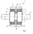
- Fig. 1 a longitudinal section through a cylindrical spherical plain bearing 1 is shown in the assembled state, with a hinge bushing 2, which consists of an inner metal part 3 of a circumferentially mounted thereon elastomer layer 4, an outer tube part 5 and a receiving eye 6.
- a hinge bushing 2 which consists of an inner metal part 3 of a circumferentially mounted thereon elastomer layer 4, an outer tube part 5 and a receiving eye 6.
- the inner metal part 3 has as a first bearing part on both sides in the direction of the bearing axis 7 connecting claws 8, 8 ', with which by screwing a first connection, for example, to a vehicle body part made.
- the receiving eye 6 is for example part of a wishbone.
- Fig. 2 is a longitudinal section of the hinge bush 2 is shown in the production state and in Fig. 3 is a side view.
- the basically cylindrical shape can be seen with the lateral connection claws 8, 8 '.
- a circumferential Abstützaus foundedung is mounted as a support groove 9 in the inner metal part 3, wherein projecting at the peripheral edges in the axial direction supporting shoulders 10, 10 'with a discharge slope.
- the support groove 9 is provided on the inside with an elastomer support 11 as a rubber pad.
- the intermediate plate 14, 14 ' is a rolled tube with a longitudinal gap 17 which has in the longitudinal center BlechausEnglishept 18, corresponding to about the width of the support groove 9, wherein the BlechausEnglishept 18 are bridged by narrow sheet metal webs 19, 19' in the production state of the sheet metal part, so that the two intermediate sheet metal areas 14, 14 'are connected as a one-piece pipe part.
- the intermediate plates 14, 14 ' have passage openings 20 for the rubber during the vulcanization process.
- the further intermediate plate 15, 15 'and the outer plate 13, 13' are basically the same made with the dimensions to be taken from Fig. 2.
- the inner metal part 3 and the sheet metal webs 19 still contiguous intermediate plates 14, 14 ', 15, 15' and the outer plate 13, 13 'are inserted into a Vulkanisierform, wherein in the vulcanization rubber in the area between the Elstomerring füren 12, 12 'and excess rubber optionally in addition to the elastomer support 11 in the support groove 9 passes.
- the hinge bushing 4 it may be necessary to cut out the excess rubber introduced here, as well as the sheet-metal webs (shown in dashed lines in FIG. 2 below, for example, between the outer sheets 13, 13 ').
- the circumferential engagement recess 21 is created between the elastomer ring layers 12, 12 '.
- the outer tube part 5 Before pressing the joint bushing 2 in the receiving eye 6, the outer tube part 5 is placed, which is shown in more detail in connection with Figures 6 and 7.
- the outer tube part 5 consists of two outer tube shell parts 22, 22 ', which are separated on the one hand by a longitudinal gap 23 and on the other hand connected to an oppositely connected to a hinge axis formed by a material dilution 24 and hinged. In the longitudinal center of a radially inwardly projecting, largely circumferential Abstützbund 25 is formed.
- the outer tube part 5 is made in this embodiment as a rotating part, wherein the support collar 25 is formed by further processing.
- the outer tube part 5 is plugged in the unfolded state on the joint bush 2 and closed tubular, wherein the support collar 25 engages in the engagement recess 21 and the support groove 9.
- the outer diameter is greater than the inner diameter of the receiving eye 6.
- the diameter of the joint bushing 2 with the outer tube part 5 closing their longitudinal column 16, 17, the 23rd reduced, whereby a radial bias in the elastomer layer 4 and the elastomer ring layers 12, 12 'is constructed.
- rubber displacement in the elastomer layer 4 and introduced in the support groove from the outset elastomer pad 11 of the support collar 25 is clamped in the manner shown in Fig.
- the support collar can be supported already without radial bearing load on the elastomer support 11 at the bottom of the support groove 19 with high radial spring constant, as shown in the lower half of Fig. 1.
- a gap 26 may also be provided there, as shown in the upper area of FIG. At a radial bearing load of the support collar 25 reaches only after the passage of the gap width at the bottom of the support groove 9 to the plant, which then leads to a progressively steep rising spring characteristic.
- the outer tube part 5 is axially longer in the manufacturing state than the receiving eye 6, so that the outer tube part 5 projects after pressing into the receiving eye 6 with edge regions on both sides. These edge regions are, as shown in FIG. 1, flanged radially outwards onto the receiving eye side edges, in each case with a flanged edge 27, 27 ', for axial support and axial securing.
- the axial and radial support takes place essentially via the support collar and the relatively thin-walled elastomer support in the support groove 9 of the inner metal part 3, while the rotation is recorded at relatively low torsional rigidity in the relatively thick elastomer ring layers 12, 12 ', wherein the sheet metal inserts mounted therein support radial load capacity and axial rigidity together with the support shoulders 10, 10 '.
- FIGS. 8 and 9 show an alternative embodiment of a joint bush 2, the difference being in another connection technology for the inner metal part 3, which instead of connecting claws 8, 8 'has an axially continuous bore 28 for receiving a bolt (not shown) for a connection fitting has. Otherwise it is the training and operation equal to the embodiment of Figures 2 and 3.
- FIGS. 10 and 11 show an alternative embodiment of an outer tube part 5, wherein the difference here lies in a different design and production of the support collar 25 compared with the embodiment according to FIGS. 6 and 7.
- the outer tube part 5 is designed here as a stamped sheet metal part, wherein the support collar 25 is designed as a radially inwardly facing embossing fold 29.
- a sickle-shaped sheet metal insert 30, 30 ' (FIG. 12) is pressed into the outer tube shell parts 22, 22' in order to increase the stability and for additional axial broadening.
Abstract
Description
Die Erfindung betrifft ein Gelenklager, insbesondere an einer Vorderachse einer Einzelradaufhängung eines Nutzfahrzeugs nach dem Oberbegriff des Anspruchs 1.The invention relates to a spherical plain bearing, in particular on a front axle of an independent wheel suspension of a commercial vehicle according to the preamble of claim 1.
Ein gattungsgemäßes bekanntes Gelenklager (
Konkret ist hier die Gummischicht in ihrer axialen Längsmitte durch eine umlaufende Ausnehmung in zwei seitliche Gelenkbuchsenbereiche geteilt, wobei in deren Gummischichten jeweils ein umlaufendes Außenblech anvulkanisiert und ein umlaufendes Zwischenblech einvulkanisiert sind. Zwischen den Gelenkbuchsenbereichen greift ein am inneren Metallteil radial abstehender, umlaufender Anschlagbund ein, welcher sich nach einem vorgegebenen relativ kleinen Federweg sowohl radial zum Aufnahmeauge hin als auch axial an den Gelenkbuchsenbereichen in seiner Anschlagfunktion bei entsprechender Lagerauslenkung abstützt. Für eine geeignete Montage beim Einpressen der Gelenkbuchse in das Aufnahmeauge wird diese zusammen mit einem die Gelenkbuchse insgesamt umfassenden Montagerohr eingepresst. Das Montagerohr wird zudem an jeweils stirnseitigen Überständen für eine axiale Lagefixierung in Teilabschnitten zu den Gelenkbuchsenbereichen sowie in Teilabschnitten zum Aufnahmeauge hin umgebördelt. Damit wird hier ein relativ verdrehweiches Gelenklager mit durch den radialen Anschlag nach einer geringen radialen Einfederung stark ansteigender radialer Federkennung erhalten. In Axialrichtung ist dieses Gelenklager jedoch verglichen mit der Radialrichtung wesentlich weicher. Obwohl hier in Radialrichtung hohe Kräfte bei geringer Drehsteifigkeit aufgenommen werden können, ist eine hohe Kraftaufnahme in Axialrichtung nicht gegeben, so dass das Gelenklager für entsprechende Einsätze wenig geeignet ist.Specifically, here the rubber layer is divided in its axial longitudinal center by a circumferential recess in two lateral joint bush areas, wherein in the rubber layers each a circumferential outer panel vulcanized and a circumferential intermediate plate are vulcanized. Between the joint bush areas engages a radially abhangender on the inner metal part, circumferential stop collar, which according to a predetermined relatively small spring travel both radially towards the receiving eye and axially on the joint bush areas in its stop function at corresponding Bearing deflection supported. For a suitable installation when pressing the joint bushing into the receiving eye this is pressed together with a total of the joint bush comprehensive mounting tube. The mounting tube is also crimped on each front projections for axial positional fixation in sections to the joint bush areas and in sections to the receiving eye. This is a relatively verdreheses spherical plain bearing obtained by the radial stop after a small radial deflection strongly increasing radial spring rate. In the axial direction of this joint bearing, however, compared to the radial direction is much softer. Although here in the radial direction high forces can be absorbed with low torsional stiffness, a high power absorption in the axial direction is not given, so that the joint bearing is suitable for appropriate applications.
Aufgabe der Erfindung ist es, ein Gelenklager für elastische, hohe radiale Abstützkräfte und für elastische, hohe axiale Abstützkräfte bei geringer Verdrehsteifigkeit zu schaffen.The object of the invention is to provide a spherical plain bearing for elastic, high radial support forces and elastic, high axial support forces with low torsional stiffness.
Diese Aufgabe wird mit den Merkmalen des Anspruchs 1 gelöst.This object is achieved with the features of claim 1.
Gemäß Anspruch 1 sind durch die Elastomerschicht wenigstens eine Eingriffausnehmung und darunter zugeordnet im inneren Metallteil eine Abstützausnehmung angeordnet, wobei die Abstützausnehmung inseitig eine Elastomerauflage aufweist. Zwischen dem Aufnahmeauge und der Elastomerschicht ist ein Außenrohrteil eingesetzt, das wenigstens einen radial nach innen gerichteten Abstützvorsprung aufweist, der durch die Eingriffausnehmung in die Abstützausnehmung eingreift. Dieser Abstützvorsprung ist so zu dimensionieren, dass er sich axial über die Elastomerauflage in der Abstützausnehmung abstützt, so dass dadurch eine hohe axiale Federkonstante vorliegt. Ebenso kann unmittelbar oder nach kurzem radialen Einfederweg eine Abstützung des Abstützvorsprungs jeweils am Boden der Abstützausnehmung über eine dortige Elastomerauflage erfolgen, wodurch auch eine hohe Radialfederkonstante gegeben ist. Der Eingriff des wenigstens einen Abstützvorsprungs in die jeweils zugeordnete Abstützausnehmung bzw. die zusammenwirkenden geometrischen Formen der Abstützausnehmung und des Abstützvorsprungs sind zudem so zu dimensionieren, dass hier keine oder nur eine geringe Abstützfunktion in Verdrehrichtung, vorliegt, so dass eine Verdrehung mit geringer Verdrehsteifigkeit in der umfangsseitigen Elastomerschicht aufgenommen wird.In accordance with claim 1, at least one engagement recess and associated therewith in the inner metal part are arranged by the elastomer layer a Abstützausnehmung, wherein the Abstützausnehmung has an elastomeric pad on the inside. Between the receiving eye and the elastomer layer, an outer tube part is used, which has at least one radially inwardly directed support projection, which engages through the engagement recess in the Abstützausnehmung. This support projection is to be dimensioned so that it is supported axially over the elastomer support in the Abstützausnehmung, so that thereby a high axial spring constant is present. Likewise, directly or after a short radial compression travel, a support of the supporting projection in each case at the bottom of the Abstützausnehmung via a there Elastomerauflage done, whereby a high radial spring constant is given. The engagement of the at least one support projection in the respectively assigned Abstützausnehmung or the cooperating geometric shapes of the Abstützausnehmung and the Abstützvorsprungs are also to be dimensioned so that there is no or only a small support function in the direction of rotation, so that a rotation with low torsional stiffness in the circumferential elastomer layer is added.
Gemäß Anspruch 2 ist der wenigstens eine Abstützvorsprung unter Vorspannung im Elastomermaterial der Elastomerschicht in der Eingriffausnehmung und/oder der Elastomerauflage in der Abstützausnehmung eingesetzt. Damit besteht durch die Vorgabe einer solchen Vorspannung mit eine Dimensionierungsmöglichkeit für die axiale und radiale Federkennlinie. Beispielsweise kann jedoch auch für einen radialen Anschlag eines Abstützvorsprungs am Boden der Abstützausnehmung ein freier Federweg vorgesehen sein, nach dem der Abstützvorsprung erst in seine Abstützposition an der dortigen Elastomerauflage gelangt. Damit sind für konkrete Anwendungen große Gestaltungsmöglichkeiten und genaue Anpassungen möglich.According to claim 2, the at least one support projection is inserted under prestress in the elastomer material of the elastomer layer in the engagement recess and / or the elastomer support in the support recess. This is due to the specification of such a bias with a dimensioning option for the axial and radial spring characteristic. For example, however, a free spring travel can also be provided for a radial abutment of a support projection at the bottom of the support recess, after which the support projection first reaches its support position on the elastomer support there. This makes great design options and precise adjustments possible for specific applications.
Mit Anspruch 3 wird vorgeschlagen mehrere Abstützvorsprünge und zugeordnete Eingriffausnehmungen sowie Abstützausnehmungen umfangsseitig verteilt anzuordnen.With claim 3 it is proposed to arrange a plurality of support projections and associated engagement recesses and Abstützausnehmungen circumferentially distributed.
In einer besonders bevorzugten Ausführungsform nach Anspruch 4 soll jedoch die wenigstens eine Eingriffausnehmung und die zugeordnete Abstützausnehmung als wenigstens eine in einer Radialebene segmentweise oder bevorzugt insgesamt umlaufende Eingriff und Abstütznut ausgebildet sein. Am Außenrohrteil ist dazu in einer Positivform ein umlaufender Abstützbund ausgebildet, wobei die Elastomerschicht umlaufend in axial beabstandete Elastomerringschichten geteilt ist. Bei einer umlaufenden Eingriff und Abstütznut ist die erforderliche Verdrehweichheit gegeben, da für den Abstützbund keine wesentliche Abstützung in Verdrehrichtung vorliegt. Bei einer segmentweisen Ausbildung ist zum Erhalt der Verdrehweichheit die Eingriff- und Abstütznut in Umfangsrichtung länger als der jeweils eingreifende Abstützbundabschnitt auszuführen. In einer besonders bevorzugten Weiterbildung nach Anspruch 5 liegt die Radialebene mit einem Abstützbund in der axialen Gelenkbuchsen-Längsmitte. Damit liegen vorteilhaft hinsichtlich der Lagerbelastungen und der Herstellung symmetrische Verhältnisse vor.In a particularly preferred embodiment according to
Um das Außenrohrteil mit einem oder mehreren radial nach innen weisenden Abstützvorsprüngen, insbesondere einem umlaufenden oder segmentweisen Abstützbund vor dem Einpressvorgang auf die Gelenkbuchse aufsteckbar zu machen, wird mit Anspruch 6 vorgeschlagen, das Außenrohrteil aus wenigstens zwei in Längsrichtung geteilten Außenrohrschalenteilen herzustellen, welche nach dem Einpressvorgang ringförmig geschlossen sind. Alternativ dazu kann in einer Weiterbildung das Außenrohrteil nach Anspruch 7 aus zwei Außenrohrschalenteilen bestehen, die durch einen Längsspalt einerseits getrennt sind und gegenüberliegend an einer materialeinheitlichen, durch eine Materialverdünnung gebildeten Scharnierachse aufklappbar verbunden sind.In order to make the outer tube part with one or more radially inwardly directed Abstützvorsprüngen, in particular a circumferential or segment Abstützbund before the press-fitting on the joint socket is proposed with
Das Außenrohrteil nach Anspruch 8 kann als Gussteil oder als Drehteil hergestellt sein, an dem durch weitere Bearbeitung die Konturen für Abstützvorsprünge und/oder Abstützbünde hergestellt sind. Alternativ dazu kann nach Anspruch 9 ein Außenrohrteil in einem gegebenenfalls kostengünstigeren Verfahren als Fließpressteil oder als Blechprägeteil ausgebildet werden. Bei einem Blechprägeteil kann der Abstützbund, insbesondere ein umlaufender, längsmittiger Abstützbund als nach radial innen weisende Prägefalte hergestellt sein. Die Prägefaltenstärke und damit die Stabilität des Außenrohrteils kann, falls erforderlich, durch Blecheinlegeteile in der Prägefalte erhöht werden.The outer tube part according to
Nach dem Einpressen der Gelenkbuchse zusammen mit dem Außenrohrteil in das Aufnahmeauge wird ein starker Reibschluss zwischen der Innenseite des Aufnahmeauges und der Außenseite des Außenrohrteils hergestellt, der bei üblichen Betriebsbedingungen Relativbewegungen, insbesondere Verdrehungen und ein axiales Auswandern aus dem Aufnahmeauge unterbindet. Falls erforderlich, kann jedoch nach Anspruch 10 einfach eine Axialfixierung dadurch hergestellt werden, dass das Außenrohrteil im Herstellzustand axial länger als das Aufnahmeauge ist und nach dem Einpressvorgang das Außenrohrteil mit beidseitig axial überstehenden Randkanten umlaufend oder bereichsweise nach radial außen zum Aufnahmeauge hin umgebördelt wird. Dadurch erfolgt insbesondere eine verbesserte Axialkraftabstützung, die vom inneren Metallteil über den Abstützvorsprung auf das Außenrohrteil und von dort über den Reibschluss und zusätzlich über die vorstehende Axialabstützung in das Aufnahmeauge eingeleitet wird.After pressing the joint bush together with the outer tube part in the receiving eye a strong frictional engagement between the inside of the receiving eye and the outside of the outer tube part is made, which prevents relative movement, in particular rotations and an axial emigration from the receiving eye under normal operating conditions. If necessary, however, according to
In einer bevorzugten Ausführungsform nach Anspruch 11 sind die Gelenkbuchse und das innere Metallteil sowie das Aufnahmeauge zylindrisch ausgeführt. Grundsätzlich können jedoch auch andere prismatische oder ovale Formen verwendet werden.In a preferred embodiment according to
In einer vorteilhaften Weiterbildung nach Anspruch 12 ist auf der Elastomerschicht ein radial äußeres umlaufendes Außenblech angehaftet, vorzugsweise anvulkanisiert und/oder in der Elastomerschicht wenigstens ein umlaufendes Zwischenblech eingebettet, vorzugsweise einvulkanisiert. Das Außenblech und/oder das wenigstens eine Zwischenblech weisen dabei im Bereich der Eingriffausnehmung ebenfalls zugeordnete Blechausnehmungen auf, da auch hier durch diese Blechausnehmungen der jeweils zugeordnete Abstützvorsprung nach radial innen durchgreift.In an advantageous embodiment according to
Für eine vereinfachte Herstellung sind nach Anspruch 13 im Falle einer umlaufenden Blechausnehmung bei einer entsprechend umlaufenden Eingriffausnehmung in der Elastomerschicht die jeweils zwei dann gebildeten Blechringteile im Herstellzustand durch Blechstege verbunden. Diese werden entweder vor dem Eingriff des zugeordneten Abstützbunds, insbesondere nach einem Vulkanisiervorgang herausgeschnitten oder beim Eingriff des Abstützbunds abgeschert und weggedrückt.For a simplified production are according to
Im Zuge der Herstellung der Gelenkbuchse kann es nach Anspruch 14 erforderlich sein, überschüssiges Elastomermaterial, insbesondere nach einem Vulkanisiervorgang, aus der Eingriffausnehmung und gegebenenfalls aus der Abstützausnehmung herauszuschneiden.In the course of producing the joint bush, it may be necessary according to claim 14 to cut out excess elastomer material, in particular after a vulcanization process, out of the engagement recess and optionally out of the support recess.
Für eine hohe Verdrehweichheit bei hoher Axialfederkonstante und hoher Radialfederkonstante wird nach Anspruch 15 die umfangsseitige Elastomerschichtdicke auf dem inneren Metallteil relativ dick im Vergleich zur Elastomerauflage in der Abstützausnehmung dimensioniert, vorzugsweise etwa in einem Dickenverhältnis von ca. 3:1.For a high Verdrehweichheit with high Axialfederkonstante and high radial spring constant according to
Für eine geeignete Aufbringung der erforderlichen hohen Vorspannung in der Elastomerschicht, weisen gemäß Anspruch 16 die Elastomerschicht im nicht vorgespannten Herstellzustand und gegebenenfalls das Außenblech sowie Zwischenbleche einen Längsschlitz auf, der sich vorzugsweise V-förmig mit seiner Schlitztiefe bis zum inneren Metallteil erstreckt. Im fertig montierten Zustand ist die Gelenkbuchse mit Außenrohrteil mit gegenüber dem Aufnahmeauge im unbelasteten Zustand größeren Durchmesser axial unter Aufbringung einer radialen Vorspannung in das Aufnahmeauge bei dann geschlossenem Längsschlitz eingepresst.For a suitable application of the required high bias voltage in the elastomer layer, according to
Für eine weitere Erhöhung der Axialfederkonstante wird mit Anspruch 17 vorgeschlagen, dass am inneren Metallteil wenigstens eine in Radialrichtung auskragende Abstützschulter, vorzugsweise zwei zu beiden Seiten einer umlaufenden längsmittigen Eingriffausnehmung angeordnete Abstützschultern angebracht sind.For a further increase in the Axialfederkonstante is proposed by
Gemäß Anspruch 18 wird als Elastomermaterial zweckmäßig ein vulkanisierbares Gummimaterial verwendet.According to
Das metallische Innenteil stellt das zweite Lagerteil dar und ist beispielsweise mit einem Achskörper oder einem Teil des Fahrzeugaufbaus zu verbinden. Dazu stehen nach Anspruch 19 an sich bekannte Anschlusstechniken zur Verfügung, beispielsweise als einseitig oder beidseitig angebrachte Anschlusszapfen oder Anschlusspratzen. Alternativ kann das metallische Innenteil auch als stabiles Innenrohrteil mit einer axialen Durchgangsbohrung zur Aufnahme einer Anschlussverschraubung ausgeführt sein.The metallic inner part represents the second bearing part and is to be connected for example to an axle body or a part of the vehicle body. For this purpose, according to
Anhand einer Zeichnung wird die Erfindung näher erläutert.Reference to a drawing, the invention is explained in detail.
Es zeigen:
- Fig. 1
- einen Längsschnitt durch ein montiertes Gelenklager,
- Fig. 2
- einen Längsschnitt durch eine Gelenkbuchse im Herstellzustand als Bestandteil des Gelenklagers nach Fig. 1,
- Fig. 3
- eine Seitenansicht der Gelenkbuchse nach Fig. 2,
- Fig. 4
- eine Längsansicht eines Außenblechs bzw. eines Zwischenblechs im Herstellzustand,
- Fig. 5
- eine Seitenansicht des Außenblechs/Zwischenblechs nach Fig. 4,
- Fig. 6
- einen Längsschnitt durch ein Außenrohrteil einer ersten Ausführungsform,
- Fig. 7
- eine Seitenansicht des Außenrohrteils nach Fig. 6,
- Fig. 8
- einen Längsschnitt durch eine Gelenkbuchse einer alternativen Ausführungsform,
- Fig. 9
- eine Seitenansicht der Gelenkbuchse nach Fig. 8,
- Fig. 10
- einen Längsschnitt durch ein Außenrohrteil einer zweiten Ausführungsform,
- Fig. 11
- eine Seitenansicht des Außenrohrteils nach Fig. 10, und
- Fig. 12
- sichelförmige Blecheinlegeteile, die im Außenrohrteil nach Fig. 10 verwendet sind.
- Fig. 1
- a longitudinal section through a mounted spherical plain bearings,
- Fig. 2
- a longitudinal section through a hinge bush in the manufacturing state as part of the joint bearing according to Fig. 1,
- Fig. 3
- a side view of the joint socket according to Fig. 2,
- Fig. 4
- a longitudinal view of an outer sheet or an intermediate sheet in the manufacturing state,
- Fig. 5
- a side view of the outer panel / intermediate plate of FIG. 4,
- Fig. 6
- a longitudinal section through an outer tube part of a first embodiment,
- Fig. 7
- a side view of the outer tube part of FIG. 6,
- Fig. 8
- a longitudinal section through a joint socket of an alternative embodiment,
- Fig. 9
- a side view of the joint socket of Fig. 8,
- Fig. 10
- a longitudinal section through an outer tube part of a second embodiment,
- Fig. 11
- a side view of the outer tube part of FIG. 10, and
- Fig. 12
- sickle-shaped Blecheinlegeteile which are used in the outer tube part of FIG. 10.
In Fig. 1 ist ein Längsschnitt durch ein zylindrisches Gelenklager 1 im fertig montierten Zustand dargestellt, mit einer Gelenkbuchse 2, die aus einem inneren Metallteil 3 einer umfangsseitig darauf angebrachten Elastomerschicht 4, einem Außenrohrteil 5 und einem Aufnahmeauge 6 besteht.In Fig. 1 a longitudinal section through a cylindrical spherical plain bearing 1 is shown in the assembled state, with a hinge bushing 2, which consists of an inner metal part 3 of a circumferentially mounted thereon
Das innere Metallteil 3 weist als erstes Lagerteil beidseitig in Richtung der Lagerachse 7 Anschlusspratzen 8, 8' auf, mit denen durch Verschraubungen eine erste Verbindung, beispielsweise zu einem Fahrzeugaufbauteil, hergestellt ist. Das Aufnahmeauge 6 ist beispielsweise Bestandteil eines Achslenkers.The inner metal part 3 has as a first bearing part on both sides in the direction of the bearing
Die einzelnen Bauteile des Gelenklagers 1 werden weiter anhand der Figuren 2 bis 7 erläutert:The individual components of the joint bearing 1 will be further explained with reference to FIGS 2 to 7:
In Fig. 2 ist ein Längsschnitt der Gelenkbuchse 2 im Herstellzustand gezeigt und in Fig. 3 eine Seitenansicht. Am inneren Metallteil 3 ist wiederum die grundsätzlich zylindrische Form erkennbar mit den seitlichen Anschlusspratzen 8, 8'. In einer Radialebene in der Längsmitte ist im inneren Metallteil 3 eine umlaufende Abstützausnehmung als Abstütznut 9 angebracht, wobei an deren umlaufenden Rändern in Axialrichtung wirkende Abstützschultern 10, 10' mit einer Auslaufschräge auskragen. Die Abstütznut 9 ist inseitig mit einer Elastomerauflage 11 als Gummiauflage versehen. Auf die beiden durch die Abstütznut 9 beabstandeten Zylinderbereiche des inneren Metallteils 3 sind als Elastomerschicht 4 jeweils Elastomerringschichten 12, 12' mit Gummimaterial aufvulkanisiert, an deren Umfangsbereichen jeweils ein umlaufendes Außenblech 13, 13' aufvulkanisiert ist und in der Schichtdicke zwei radial übereinanderliegende Zwischenbleche 14, 14' und 15, 15' einvulkanisiert sind.In Fig. 2 is a longitudinal section of the hinge bush 2 is shown in the production state and in Fig. 3 is a side view. On the inner metal part 3, in turn, the basically cylindrical shape can be seen with the
Zudem weist die Elastomerschicht 4 bzw. die Elastomerringschichten 12, 12' einen V-förmigen Längsschlitz 16 auf, der sich auch durch die Außenbleche 13, 13' und die Zwischenbleche 14, 14' und 15, 15' bis zum inneren Metallteil 3 erstreckt.In addition, the
In den Figuren 4 und 5 ist das radial innere Zwischenblech mit seinen beiden Bereichen 14, 14' in der Größe entsprechend Fig. 1 dargestellt. Das Zwischenblech 14, 14' ist ein gerolltes Rohr mit einem Längsspalt 17, welches in der Längsmitte Blechausnehmungen 18 aufweist, entsprechend etwa der Breite der Abstütznut 9, wobei die Blechausnehmungen 18 durch schmale Blechstege 19, 19' im Herstellzustand des Blechteils überbrückt sind, so dass die beiden Zwischenblechbereiche 14, 14' als einstückiges Rohrteil zusammenhängen. Zudem weisen die Zwischenbleche 14, 14' Durchtrittöffnungen 20 für den Gummi während des Vulkanisierprozesses auf. Das weitere Zwischenblech 15, 15' sowie das Außenblech 13, 13' sind mit den aus Fig. 2 zu entnehmenden Abmessungen grundsätzlich gleich hergestellt.In Figures 4 and 5, the radially inner intermediate plate with its two
Zur Herstellung der Gelenkbuchse 4 werden das innere Metallteil 3 und die durch die Blechstege 19 noch zusammenhängenden Zwischenbleche 14, 14', 15, 15' und das Außenblech 13, 13' in eine Vulkanisierform eingelegt, wobei beim Vulkanisiervorgang Gummi auch in den Bereich zwischen die Elstomerringschichten 12, 12' und überschüssiger Gummi gegebenenfalls zusätzlich zur Elastomerauflage 11 in die Abstütznut 9 gelangt. Um die Gelenkbuchse 4 wie in Fig. 2 dargestellt zu erhalten, ist es gegebenenfalls erforderlich, den hier überschüssig eingebrachten Gummi sowie die Blechstege (in Fig. 2 unten beispielsweise zwischen den Außenblechen 13, 13' strichliert dargestellt) auszuschneiden. Dadurch wird zwischen den Elastomerringschichten 12, 12' die umlaufende Eingriffausnehmung 21 geschaffen.To produce the
Vor dem Einpressen der Gelenkbuchse 2 in das Aufnahmeauge 6 wird das Außenrohrteil 5 aufgesetzt, das in Verbindung mit den Figuren 6 und 7 näher dargestellt ist. Das Außenrohrteil 5 besteht aus zwei Außenrohrschalenteilen 22, 22', die einerseits durch einen Längsspalt 23 getrennt sind und andererseits gegenüberliegend an einer durch eine Materialverdünnung gebildeten Scharnierachse 24 zusammenhängend verbunden und aufklappbar sind. In der Längsmitte ist ein nach radial innen ragender, weitgehend umlaufender Abstützbund 25 ausgebildet. Das Außenrohrteil 5 ist in dieser Ausführungsform als Drehteil hergestellt, wobei der Abstützbund 25 durch weitere Bearbeitungen ausgebildet ist.Before pressing the joint bushing 2 in the receiving
Das Außenrohrteil 5 wird im aufgeklappten Zustand auf die Gelenkbuchse 2 aufgesteckt und rohrförmig geschlossen, wobei der Abstützbund 25 in die Eingriffausnehmung 21 und die Abstütznut 9 eingreift. In diesem Zustand ist der Außendurchmesser größer als der Innendurchmesser des Aufnahmeauges 6. Beim Einpressvorgang in das Aufnahmeauge 6 zum fertig montierten Zustand (Fig. 1) wird daher der Durchmesser der Gelenkbuchse 2 mit dem Außenrohrteil 5 unter Schließung deren, Längsspalte 16, 17, 23 verringert, wodurch eine radiale Vorspannung in der Elastomerschicht 4 bzw. den Elastomerringschichten 12, 12' aufgebaut wird. Durch Gummiverdrängung in der Elastomerschicht 4 und die in der Abstütznut von vornherein eingebrachte Elastomerauflage 11 wird der Abstützbund 25 in der in Fig. 1 gezeigten Weise jeweils seitlich im Elastomermaterial eingespannt, wobei er sich bei einer axialen Lagerauslenkung, insbesondere an einer Seitenwange der Abstütznut 9 über die dortige Elastomerauflage 11 mit hoher Axialfederkonstante abstützt. Zudem kann sich der Abstützbund bereits ohne radiale Lagerbelastung über die Elastomerauflage 11 am Boden der Abstütznut 19 mit hoher radialer Federkonstante abstützen, wie dies in der unteren Hälfte von Fig. 1 gezeigt ist. Alternativ kann dort auch ein Spalt 26 vorgesehen sein, wie im oberen Bereich von Fig. 1 dargestellt. Bei einer radialen Lagerbelastung gelangt der Abstützbund 25 erst nach dem Durchgang der Spaltbreite am Boden der Abstütznut 9 zur Anlage, was dann zu einer progressiv steil ansteigenden Federkennlinie führt.The
Das Außenrohrteil 5 ist im Herstellzustand axial länger als das Aufnahmeauge 6, so dass das Außenrohrteil 5 nach dem Einpressen in das Aufnahmeauge 6 mit Randbereichen beidseitig übersteht. Diese Randbereiche sind, wie in Fig. 1 dargestellt, zur Axialabstützung und Axialsicherung nach radial außen auf die Aufnahmeaugenseitenränder jeweils mit einem Bördelrand 27, 27' umgebördelt. Die axiale und radiale Abstützung erfolgt im wesentlichen über den Abstützbund und die relativ dünnwandige Elastomerauflage in der Abstütznut 9 des inneren Metallteils 3, während die Verdrehung bei relativ geringer Verdrehsteifigkeit in den relativ dicken Elastomerringschichten 12, 12' aufgenommen wird, wobei die darin angebrachten Blecheinlagen die radiale Tragfähigkeit und axiale Steifigkeit zusammen mit den Abstützschultern 10, 10' unterstützen.The
In den Figuren 8 und 9 ist eine alternative Ausführungsform einer Gelenkbuchse 2 dargestellt, wobei der Unterschied in einer anderen Anschlusstechnik für das innere Metallteil 3 besteht, welches anstelle von Anschlusspratzen 8, 8' eine axial durchgehende Bohrung 28 zur Aufnahme eines (nicht dargestellten) Schraubenbolzens für eine Anschlussverschraubung aufweist. Im übrigen ist die Ausbildung und Funktionsweise gleich der Ausführungsform nach den Figuren 2 und 3.FIGS. 8 and 9 show an alternative embodiment of a joint bush 2, the difference being in another connection technology for the inner metal part 3, which instead of connecting
In den Figuren 10 und 11 ist eine alternative Ausführungsform eines Außenrohrteils 5. dargestellt, wobei der Unterschied hier im Vergleich zur Ausführungsform nach den Figuren 6 und 7 in einer anderen Ausbildung und Herstellung des Abstützbunds 25 liegt. Dazu ist das Außenrohrteil 5 hier als Blechprägeteil ausgeführt, wobei der Abstützbund 25 als nach radial innen weisende Prägefalte 29 ausgeführt ist. Zwischen den dabei benachbarten Wandstärken der Prägefalte 29 ist zur Erhöhung der Stabilität und für eine zusätzliche axiale Verbreiterung jeweils in den Außenrohrschalenteilen 22, 22' ein sichelartig ausgebildetes Blecheinlegeteil 30, 30' (Fig. 12) mit eingepresst.FIGS. 10 and 11 show an alternative embodiment of an
Claims (19)
mit einer Gelenkbuchse (2) als Elastomermetallteil bestehend aus einem inneren Metallteil (3) als ersten Lagerteil, das insbesondere mit einem Fahrzeugaufbau verbindbar ist, und auf dem eine umfangsseitige Elastomerschicht (4) festhaftend angebracht, vorzugsweise eine Gummischicht aufvulkanisiert ist, und mit einem Aufnahmeauge (6) als zweitem Lagerteil, in das die Gelenkbuchse (2) mit radialer Vorspannung in der Elastomerschicht (4) eingepresst ist,
dadurch gekennzeichnet,
dass durch die Elastomerschicht (4) wenigstens eine Eingriffausnehmung (21) und darunter zugeordnet im inneren Metallteil (3) eine Abstützausnehmung (9) angeordnet sind, wobei die Abstützausnehmung (9) inseitig eine Elastomerauflage (11) aufweist,
dass zwischen dem Aufnahmeauge (6) und der Elastomerschicht (4) ein Außenrohrteil (5) eingesetzt ist, das wenigstens einen radial nach innen gerichteten Abstützvorsprung (25) aufweist, der durch die Eingriffausnehmung (21) in die Abstützausnehmung (9) eingreift.Spherical bearing, in particular on a front axle of a Einzeiradaufhängung a commercial vehicle
with a joint bushing (2) as an elastomeric metal part consisting of an inner metal part (3) as a first bearing part, which is in particular connectable to a vehicle body, and on which a peripheral elastomer layer (4) adherently attached, preferably a rubber layer is vulcanized, and with a receiving eye (6) as a second bearing part, in which the joint bush (2) is pressed with radial prestress in the elastomer layer (4),
characterized,
in that at least one engagement recess (21) and associated therewith in the inner metal part (3) are arranged a support recess (9) through the elastomer layer (4), wherein the support recess (9) has an elastomer support (11) on the inside,
in that an outer tube part (5) is inserted between the receiving eye (6) and the elastomer layer (4), which has at least one radially inwardly directed supporting projection (25) which engages in the supporting recess (9) through the engagement recess (21).
Applications Claiming Priority (1)
| Application Number | Priority Date | Filing Date | Title |
|---|---|---|---|
| DE102006005689A DE102006005689A1 (en) | 2006-02-08 | 2006-02-08 | Spherical bearing, in particular on a front axle of an independent suspension of a commercial vehicle |
Publications (3)
| Publication Number | Publication Date |
|---|---|
| EP1818560A2 true EP1818560A2 (en) | 2007-08-15 |
| EP1818560A3 EP1818560A3 (en) | 2009-08-19 |
| EP1818560B1 EP1818560B1 (en) | 2011-07-20 |
Family
ID=37964528
Family Applications (1)
| Application Number | Title | Priority Date | Filing Date |
|---|---|---|---|
| EP07000959A Not-in-force EP1818560B1 (en) | 2006-02-08 | 2007-01-18 | Pivot bearing, especially for front axle of an independent wheel suspension of a commercial vehicle |
Country Status (3)
| Country | Link |
|---|---|
| EP (1) | EP1818560B1 (en) |
| AT (1) | ATE517271T1 (en) |
| DE (1) | DE102006005689A1 (en) |
Cited By (1)
| Publication number | Priority date | Publication date | Assignee | Title |
|---|---|---|---|---|
| DE102016216861A1 (en) | 2016-09-06 | 2018-03-08 | Bayerische Motoren Werke Aktiengesellschaft | Bearing for connecting an axle carrier to a body of a vehicle |
Families Citing this family (2)
| Publication number | Priority date | Publication date | Assignee | Title |
|---|---|---|---|---|
| DE102009025429A1 (en) * | 2009-06-16 | 2011-01-05 | Benteler Automobiltechnik Gmbh | Handlebar assembly and method of manufacturing a handlebar assembly |
| KR102258238B1 (en) * | 2019-11-07 | 2021-05-31 | (주)디티알 | A foldable mount bushing |
Citations (4)
| Publication number | Priority date | Publication date | Assignee | Title |
|---|---|---|---|---|
| JPS6161340U (en) * | 1984-09-28 | 1986-04-25 | ||
| JPH0389036A (en) * | 1989-08-31 | 1991-04-15 | Toyoda Gosei Co Ltd | Fixing method of vibration isolating bushing |
| DE4127092C1 (en) * | 1991-08-16 | 1993-01-07 | Joern Gmbh, 7012 Fellbach, De | Joint bearing for car axle link - has outer tube and associated rubber layer separated in axial bearing centre to form cylindrical intermediate space |
| JPH06129461A (en) * | 1992-10-19 | 1994-05-10 | Toyota Motor Corp | Cushion assembly |
-
2006
- 2006-02-08 DE DE102006005689A patent/DE102006005689A1/en not_active Withdrawn
-
2007
- 2007-01-18 AT AT07000959T patent/ATE517271T1/en active
- 2007-01-18 EP EP07000959A patent/EP1818560B1/en not_active Not-in-force
Patent Citations (4)
| Publication number | Priority date | Publication date | Assignee | Title |
|---|---|---|---|---|
| JPS6161340U (en) * | 1984-09-28 | 1986-04-25 | ||
| JPH0389036A (en) * | 1989-08-31 | 1991-04-15 | Toyoda Gosei Co Ltd | Fixing method of vibration isolating bushing |
| DE4127092C1 (en) * | 1991-08-16 | 1993-01-07 | Joern Gmbh, 7012 Fellbach, De | Joint bearing for car axle link - has outer tube and associated rubber layer separated in axial bearing centre to form cylindrical intermediate space |
| JPH06129461A (en) * | 1992-10-19 | 1994-05-10 | Toyota Motor Corp | Cushion assembly |
Cited By (1)
| Publication number | Priority date | Publication date | Assignee | Title |
|---|---|---|---|---|
| DE102016216861A1 (en) | 2016-09-06 | 2018-03-08 | Bayerische Motoren Werke Aktiengesellschaft | Bearing for connecting an axle carrier to a body of a vehicle |
Also Published As
| Publication number | Publication date |
|---|---|
| EP1818560B1 (en) | 2011-07-20 |
| ATE517271T1 (en) | 2011-08-15 |
| DE102006005689A1 (en) | 2007-08-16 |
| EP1818560A3 (en) | 2009-08-19 |
Similar Documents
| Publication | Publication Date | Title |
|---|---|---|
| DE60109298T2 (en) | BEARINGS | |
| DE102012207527B4 (en) | Sleeve joint for a vehicle | |
| DE102014013077B4 (en) | Elastomeric bearing as bushing bearing | |
| EP3221163B1 (en) | Structural component for a motor vehicle | |
| EP1691104B1 (en) | Elastic mount | |
| EP0921328B1 (en) | Bearing bush with central collar, use and method of manufacture thereof | |
| EP1998068A2 (en) | Elastic bearing with an elastomer metal socket, in particular for the support of stabilisator bar for a motor vehicle | |
| EP1818560B1 (en) | Pivot bearing, especially for front axle of an independent wheel suspension of a commercial vehicle | |
| EP1978275B1 (en) | Pivot bearing, in particular on a swivel joint between a front wheel and a rear wheel of an articulated bus | |
| DE202006000285U1 (en) | Elastomer-metal spherical plain bearings, in particular as a central spherical plain bearing of a triangular link for connecting an axle body to a vehicle body | |
| DE102015204087B4 (en) | bearing device | |
| WO2010022718A1 (en) | Ball joint | |
| EP3453911B1 (en) | Rubber bearing | |
| DE102007037704A1 (en) | Bearing arrangement with a bearing bush and method for producing a bearing bush of a bearing assembly | |
| DE10001704C1 (en) | Elastomer-metal pivot bush, with elastomer layer firmly bonded to inner elastomer bush. | |
| EP1820994B1 (en) | Rocker bearing, in particular for a chassis of a commercial vehicle | |
| EP3608552B1 (en) | Ball joint | |
| DE10145343C1 (en) | Elastic spring eye bearing for mounting a spring eye of a leaf spring on a vehicle | |
| EP3554867B1 (en) | Joint for a vehicle and method for producing such a joint | |
| EP1008781A2 (en) | Pivot bearing, particulary spring eye bearing | |
| EP1820993A1 (en) | Elastic bearing, in particular for commercial vehicle construction | |
| DE10357080B4 (en) | Elastic spring eye bearing for mounting a spring eye of a leaf spring on a vehicle | |
| DE10357079B4 (en) | Elastic spring eye bearing for mounting a spring eye of a leaf spring on a vehicle | |
| DE102012018054A1 (en) | Elastic bearing for supporting steering wheel in motor car, has connection elements for connecting mounting components on inner portion, such that connecting axis is offset from center axis at preset distance in inner portion | |
| DE102013211695A1 (en) | Punch for producing a bearing receptacle and method for producing a bearing receptacle |
Legal Events
| Date | Code | Title | Description |
|---|---|---|---|
| PUAI | Public reference made under article 153(3) epc to a published international application that has entered the european phase |
Free format text: ORIGINAL CODE: 0009012 |
|
| AK | Designated contracting states |
Kind code of ref document: A2 Designated state(s): AT BE BG CH CY CZ DE DK EE ES FI FR GB GR HU IE IS IT LI LT LU LV MC NL PL PT RO SE SI SK TR |
|
| AX | Request for extension of the european patent |
Extension state: AL BA HR MK YU |
|
| PUAL | Search report despatched |
Free format text: ORIGINAL CODE: 0009013 |
|
| AK | Designated contracting states |
Kind code of ref document: A3 Designated state(s): AT BE BG CH CY CZ DE DK EE ES FI FR GB GR HU IE IS IT LI LT LU LV MC NL PL PT RO SE SI SK TR |
|
| AX | Request for extension of the european patent |
Extension state: AL BA HR MK RS |
|
| 17P | Request for examination filed |
Effective date: 20090926 |
|
| AKX | Designation fees paid |
Designated state(s): AT BE BG CH CY CZ DE DK EE ES FI FR GB GR HU IE IS IT LI LT LU LV MC NL PL PT RO SE SI SK TR |
|
| GRAP | Despatch of communication of intention to grant a patent |
Free format text: ORIGINAL CODE: EPIDOSNIGR1 |
|
| GRAS | Grant fee paid |
Free format text: ORIGINAL CODE: EPIDOSNIGR3 |
|
| GRAA | (expected) grant |
Free format text: ORIGINAL CODE: 0009210 |
|
| AK | Designated contracting states |
Kind code of ref document: B1 Designated state(s): AT BE BG CH CY CZ DE DK EE ES FI FR GB GR HU IE IS IT LI LT LU LV MC NL PL PT RO SE SI SK TR |
|
| REG | Reference to a national code |
Ref country code: GB Ref legal event code: FG4D Free format text: NOT ENGLISH |
|
| REG | Reference to a national code |
Ref country code: CH Ref legal event code: EP |
|
| REG | Reference to a national code |
Ref country code: DE Ref legal event code: R096 Ref document number: 502007007685 Country of ref document: DE Effective date: 20110908 |
|
| REG | Reference to a national code |
Ref country code: NL Ref legal event code: VDEP Effective date: 20110720 |
|
| PG25 | Lapsed in a contracting state [announced via postgrant information from national office to epo] |
Ref country code: LT Free format text: LAPSE BECAUSE OF FAILURE TO SUBMIT A TRANSLATION OF THE DESCRIPTION OR TO PAY THE FEE WITHIN THE PRESCRIBED TIME-LIMIT Effective date: 20110720 Ref country code: SE Free format text: LAPSE BECAUSE OF FAILURE TO SUBMIT A TRANSLATION OF THE DESCRIPTION OR TO PAY THE FEE WITHIN THE PRESCRIBED TIME-LIMIT Effective date: 20110720 Ref country code: PT Free format text: LAPSE BECAUSE OF FAILURE TO SUBMIT A TRANSLATION OF THE DESCRIPTION OR TO PAY THE FEE WITHIN THE PRESCRIBED TIME-LIMIT Effective date: 20111121 Ref country code: FI Free format text: LAPSE BECAUSE OF FAILURE TO SUBMIT A TRANSLATION OF THE DESCRIPTION OR TO PAY THE FEE WITHIN THE PRESCRIBED TIME-LIMIT Effective date: 20110720 Ref country code: IS Free format text: LAPSE BECAUSE OF FAILURE TO SUBMIT A TRANSLATION OF THE DESCRIPTION OR TO PAY THE FEE WITHIN THE PRESCRIBED TIME-LIMIT Effective date: 20111120 Ref country code: NL Free format text: LAPSE BECAUSE OF FAILURE TO SUBMIT A TRANSLATION OF THE DESCRIPTION OR TO PAY THE FEE WITHIN THE PRESCRIBED TIME-LIMIT Effective date: 20110720 |
|
| REG | Reference to a national code |
Ref country code: IE Ref legal event code: FD4D |
|
| PG25 | Lapsed in a contracting state [announced via postgrant information from national office to epo] |
Ref country code: SI Free format text: LAPSE BECAUSE OF FAILURE TO SUBMIT A TRANSLATION OF THE DESCRIPTION OR TO PAY THE FEE WITHIN THE PRESCRIBED TIME-LIMIT Effective date: 20110720 Ref country code: CY Free format text: LAPSE BECAUSE OF FAILURE TO SUBMIT A TRANSLATION OF THE DESCRIPTION OR TO PAY THE FEE WITHIN THE PRESCRIBED TIME-LIMIT Effective date: 20110720 Ref country code: LV Free format text: LAPSE BECAUSE OF FAILURE TO SUBMIT A TRANSLATION OF THE DESCRIPTION OR TO PAY THE FEE WITHIN THE PRESCRIBED TIME-LIMIT Effective date: 20110720 Ref country code: GR Free format text: LAPSE BECAUSE OF FAILURE TO SUBMIT A TRANSLATION OF THE DESCRIPTION OR TO PAY THE FEE WITHIN THE PRESCRIBED TIME-LIMIT Effective date: 20111021 Ref country code: PL Free format text: LAPSE BECAUSE OF FAILURE TO SUBMIT A TRANSLATION OF THE DESCRIPTION OR TO PAY THE FEE WITHIN THE PRESCRIBED TIME-LIMIT Effective date: 20110720 |
|
| PG25 | Lapsed in a contracting state [announced via postgrant information from national office to epo] |
Ref country code: CZ Free format text: LAPSE BECAUSE OF FAILURE TO SUBMIT A TRANSLATION OF THE DESCRIPTION OR TO PAY THE FEE WITHIN THE PRESCRIBED TIME-LIMIT Effective date: 20110720 Ref country code: IE Free format text: LAPSE BECAUSE OF FAILURE TO SUBMIT A TRANSLATION OF THE DESCRIPTION OR TO PAY THE FEE WITHIN THE PRESCRIBED TIME-LIMIT Effective date: 20110720 Ref country code: SK Free format text: LAPSE BECAUSE OF FAILURE TO SUBMIT A TRANSLATION OF THE DESCRIPTION OR TO PAY THE FEE WITHIN THE PRESCRIBED TIME-LIMIT Effective date: 20110720 |
|
| PLBE | No opposition filed within time limit |
Free format text: ORIGINAL CODE: 0009261 |
|
| STAA | Information on the status of an ep patent application or granted ep patent |
Free format text: STATUS: NO OPPOSITION FILED WITHIN TIME LIMIT |
|
| PG25 | Lapsed in a contracting state [announced via postgrant information from national office to epo] |
Ref country code: IT Free format text: LAPSE BECAUSE OF FAILURE TO SUBMIT A TRANSLATION OF THE DESCRIPTION OR TO PAY THE FEE WITHIN THE PRESCRIBED TIME-LIMIT Effective date: 20110720 Ref country code: RO Free format text: LAPSE BECAUSE OF FAILURE TO SUBMIT A TRANSLATION OF THE DESCRIPTION OR TO PAY THE FEE WITHIN THE PRESCRIBED TIME-LIMIT Effective date: 20110720 Ref country code: EE Free format text: LAPSE BECAUSE OF FAILURE TO SUBMIT A TRANSLATION OF THE DESCRIPTION OR TO PAY THE FEE WITHIN THE PRESCRIBED TIME-LIMIT Effective date: 20110720 |
|
| 26N | No opposition filed |
Effective date: 20120423 |
|
| PG25 | Lapsed in a contracting state [announced via postgrant information from national office to epo] |
Ref country code: DK Free format text: LAPSE BECAUSE OF FAILURE TO SUBMIT A TRANSLATION OF THE DESCRIPTION OR TO PAY THE FEE WITHIN THE PRESCRIBED TIME-LIMIT Effective date: 20110720 |
|
| BERE | Be: lapsed |
Owner name: JORN G.M.B.H. Effective date: 20120131 |
|
| REG | Reference to a national code |
Ref country code: DE Ref legal event code: R097 Ref document number: 502007007685 Country of ref document: DE Effective date: 20120423 |
|
| PG25 | Lapsed in a contracting state [announced via postgrant information from national office to epo] |
Ref country code: MC Free format text: LAPSE BECAUSE OF NON-PAYMENT OF DUE FEES Effective date: 20120131 |
|
| REG | Reference to a national code |
Ref country code: CH Ref legal event code: PL |
|
| GBPC | Gb: european patent ceased through non-payment of renewal fee |
Effective date: 20120118 |
|
| REG | Reference to a national code |
Ref country code: FR Ref legal event code: ST Effective date: 20120928 |
|
| PG25 | Lapsed in a contracting state [announced via postgrant information from national office to epo] |
Ref country code: GB Free format text: LAPSE BECAUSE OF NON-PAYMENT OF DUE FEES Effective date: 20120118 Ref country code: LI Free format text: LAPSE BECAUSE OF NON-PAYMENT OF DUE FEES Effective date: 20120131 Ref country code: CH Free format text: LAPSE BECAUSE OF NON-PAYMENT OF DUE FEES Effective date: 20120131 |
|
| PG25 | Lapsed in a contracting state [announced via postgrant information from national office to epo] |
Ref country code: FR Free format text: LAPSE BECAUSE OF NON-PAYMENT OF DUE FEES Effective date: 20120131 Ref country code: BE Free format text: LAPSE BECAUSE OF NON-PAYMENT OF DUE FEES Effective date: 20120131 |
|
| REG | Reference to a national code |
Ref country code: AT Ref legal event code: MM01 Ref document number: 517271 Country of ref document: AT Kind code of ref document: T Effective date: 20120118 |
|
| PG25 | Lapsed in a contracting state [announced via postgrant information from national office to epo] |
Ref country code: ES Free format text: LAPSE BECAUSE OF FAILURE TO SUBMIT A TRANSLATION OF THE DESCRIPTION OR TO PAY THE FEE WITHIN THE PRESCRIBED TIME-LIMIT Effective date: 20111031 |
|
| PG25 | Lapsed in a contracting state [announced via postgrant information from national office to epo] |
Ref country code: AT Free format text: LAPSE BECAUSE OF NON-PAYMENT OF DUE FEES Effective date: 20120118 Ref country code: BG Free format text: LAPSE BECAUSE OF FAILURE TO SUBMIT A TRANSLATION OF THE DESCRIPTION OR TO PAY THE FEE WITHIN THE PRESCRIBED TIME-LIMIT Effective date: 20111020 |
|
| PG25 | Lapsed in a contracting state [announced via postgrant information from national office to epo] |
Ref country code: TR Free format text: LAPSE BECAUSE OF FAILURE TO SUBMIT A TRANSLATION OF THE DESCRIPTION OR TO PAY THE FEE WITHIN THE PRESCRIBED TIME-LIMIT Effective date: 20110720 |
|
| PG25 | Lapsed in a contracting state [announced via postgrant information from national office to epo] |
Ref country code: LU Free format text: LAPSE BECAUSE OF NON-PAYMENT OF DUE FEES Effective date: 20120118 |
|
| PG25 | Lapsed in a contracting state [announced via postgrant information from national office to epo] |
Ref country code: HU Free format text: LAPSE BECAUSE OF FAILURE TO SUBMIT A TRANSLATION OF THE DESCRIPTION OR TO PAY THE FEE WITHIN THE PRESCRIBED TIME-LIMIT Effective date: 20070118 |
|
| PGFP | Annual fee paid to national office [announced via postgrant information from national office to epo] |
Ref country code: DE Payment date: 20150127 Year of fee payment: 9 |
|
| REG | Reference to a national code |
Ref country code: DE Ref legal event code: R119 Ref document number: 502007007685 Country of ref document: DE |
|
| PG25 | Lapsed in a contracting state [announced via postgrant information from national office to epo] |
Ref country code: DE Free format text: LAPSE BECAUSE OF NON-PAYMENT OF DUE FEES Effective date: 20160802 |