EP1818541A1 - Horizontally-mounted scroll compressor - Google Patents
Horizontally-mounted scroll compressor Download PDFInfo
- Publication number
- EP1818541A1 EP1818541A1 EP07002715A EP07002715A EP1818541A1 EP 1818541 A1 EP1818541 A1 EP 1818541A1 EP 07002715 A EP07002715 A EP 07002715A EP 07002715 A EP07002715 A EP 07002715A EP 1818541 A1 EP1818541 A1 EP 1818541A1
- Authority
- EP
- European Patent Office
- Prior art keywords
- base plate
- seal member
- pressure
- groove portions
- pressure region
- Prior art date
- Legal status (The legal status is an assumption and is not a legal conclusion. Google has not performed a legal analysis and makes no representation as to the accuracy of the status listed.)
- Granted
Links
- 238000007789 sealing Methods 0.000 claims abstract description 7
- 238000007906 compression Methods 0.000 claims description 46
- 230000006835 compression Effects 0.000 claims description 45
- 239000012530 fluid Substances 0.000 claims description 4
- 239000003507 refrigerant Substances 0.000 description 46
- 230000002093 peripheral effect Effects 0.000 description 28
- 239000007788 liquid Substances 0.000 description 16
- 239000010687 lubricating oil Substances 0.000 description 13
- 239000003921 oil Substances 0.000 description 8
- 238000000926 separation method Methods 0.000 description 8
- 238000005192 partition Methods 0.000 description 6
- 239000003595 mist Substances 0.000 description 4
- 230000000903 blocking effect Effects 0.000 description 3
- 238000004891 communication Methods 0.000 description 3
- CURLTUGMZLYLDI-UHFFFAOYSA-N Carbon dioxide Chemical compound O=C=O CURLTUGMZLYLDI-UHFFFAOYSA-N 0.000 description 2
- 230000002411 adverse Effects 0.000 description 2
- 238000004378 air conditioning Methods 0.000 description 2
- 230000003247 decreasing effect Effects 0.000 description 2
- 230000000694 effects Effects 0.000 description 2
- 230000004044 response Effects 0.000 description 2
- 235000014676 Phragmites communis Nutrition 0.000 description 1
- 229910002092 carbon dioxide Inorganic materials 0.000 description 1
- 239000001569 carbon dioxide Substances 0.000 description 1
- 238000011038 discontinuous diafiltration by volume reduction Methods 0.000 description 1
- 230000001788 irregular Effects 0.000 description 1
- 238000000034 method Methods 0.000 description 1
- 230000008569 process Effects 0.000 description 1
- 230000001737 promoting effect Effects 0.000 description 1
- 239000000126 substance Substances 0.000 description 1
Images


Classifications
-
- F—MECHANICAL ENGINEERING; LIGHTING; HEATING; WEAPONS; BLASTING
- F04—POSITIVE - DISPLACEMENT MACHINES FOR LIQUIDS; PUMPS FOR LIQUIDS OR ELASTIC FLUIDS
- F04C—ROTARY-PISTON, OR OSCILLATING-PISTON, POSITIVE-DISPLACEMENT MACHINES FOR LIQUIDS; ROTARY-PISTON, OR OSCILLATING-PISTON, POSITIVE-DISPLACEMENT PUMPS
- F04C27/00—Sealing arrangements in rotary-piston pumps specially adapted for elastic fluids
- F04C27/005—Axial sealings for working fluid
-
- F—MECHANICAL ENGINEERING; LIGHTING; HEATING; WEAPONS; BLASTING
- F04—POSITIVE - DISPLACEMENT MACHINES FOR LIQUIDS; PUMPS FOR LIQUIDS OR ELASTIC FLUIDS
- F04C—ROTARY-PISTON, OR OSCILLATING-PISTON, POSITIVE-DISPLACEMENT MACHINES FOR LIQUIDS; ROTARY-PISTON, OR OSCILLATING-PISTON, POSITIVE-DISPLACEMENT PUMPS
- F04C18/00—Rotary-piston pumps specially adapted for elastic fluids
- F04C18/02—Rotary-piston pumps specially adapted for elastic fluids of arcuate-engagement type, i.e. with circular translatory movement of co-operating members, each member having the same number of teeth or tooth-equivalents
- F04C18/0207—Rotary-piston pumps specially adapted for elastic fluids of arcuate-engagement type, i.e. with circular translatory movement of co-operating members, each member having the same number of teeth or tooth-equivalents both members having co-operating elements in spiral form
- F04C18/0215—Rotary-piston pumps specially adapted for elastic fluids of arcuate-engagement type, i.e. with circular translatory movement of co-operating members, each member having the same number of teeth or tooth-equivalents both members having co-operating elements in spiral form where only one member is moving
-
- F—MECHANICAL ENGINEERING; LIGHTING; HEATING; WEAPONS; BLASTING
- F04—POSITIVE - DISPLACEMENT MACHINES FOR LIQUIDS; PUMPS FOR LIQUIDS OR ELASTIC FLUIDS
- F04C—ROTARY-PISTON, OR OSCILLATING-PISTON, POSITIVE-DISPLACEMENT MACHINES FOR LIQUIDS; ROTARY-PISTON, OR OSCILLATING-PISTON, POSITIVE-DISPLACEMENT PUMPS
- F04C29/00—Component parts, details or accessories of pumps or pumping installations, not provided for in groups F04C18/00 - F04C28/00
- F04C29/02—Lubrication; Lubricant separation
- F04C29/026—Lubricant separation
Definitions
- the present invention relates to a horizontally-mounted scroll compressor in which a crankshaft of an orbital scroll member extends horizontally, for example, a horizontally-mounted scroll compressor for compressing refrigerant for use in the refrigerant circuit of an air conditioning system.
- Conventional horizontally-mounted scroll compressors include a fixed scroll member having a fixed base plate which is fixed in the housing thereof and a fixed scroll wall which extends from the front surface of the fixed base plate, and a movable scroll member having a movable base plate and a movable scroll wall which extends from the front surface of the movable base plate.
- the fixed and movable scroll walls are engaged with each other thereby to define compression chambers therebetween.
- the fixed base plate has a front wall which is in slide contact with the front surface of the movable scroll member.
- a shaft support is provided so as to slide relative to the back surface of the movable scroll member, and a back-pressure region is defined on the back side of the movable scroll member.
- the compression chambers are moved radially inwardly while being reduced in volume by the orbital motion of the movable scroll member, thereby the scroll compressor compressing a compressible fluid.
- the movable scroll member receives a force (or a positive-pressure force) which results from the pressure in the compression chambers and is applied thereto in the thrust direction.
- a force or a positive-pressure force
- the positive-pressure force is increased.
- large load acts on the sliding portions of the movable scroll member, and the reliability of the scroll compressor may be damaged.
- Japanese Patent Application Publication No. 2005-180345 discloses a scroll compressor in which an introduction passage is provided for connecting a discharge-pressure region to a back-pressure region.
- the introduction passage passes through the sliding portion between the movable scroll member and the front wall of the fixed base plate.
- the clearance at the sliding portion is varied in response to the position of the movable scroll member in the direction in which the movable scroll member moves toward or away from the front wall of the fixed base plate.
- the cross-sectional area of the clearance where gas passes is changed to adjust the pressure in the back-pressure region.
- the pressure in the compression chambers falls, and the positive-pressure force applied to the movable scroll member becomes lower than a back-pressure force which results from the pressure in the back-pressure chamber and acts in the thrust direction.
- the movable scroll member is moved toward the front wall of the fixed base plate.
- the clearance at the sliding portion between the movable scroll member and the front wall of the fixed scroll member becomes minimum, thereby preventing the refrigerant gas from being introduced from the discharge-pressure region to the back-pressure region.
- the pressure in the back-pressure chamber tends to fall.
- Japanese Patent Application Publication No. 8-121366 discloses a vertical-mounted scroll compressor in which a seal member is provided dividing the back-pressure region in the housing into two spaces.
- the seal member has a groove for supplying lubricating oil to the sliding portion between the fixed and movable scroll members.
- the quantity of the lubricating oil supplied to the sliding portion is adjusted by changing the number, the width and the depth of the groove.
- the atmosphere in the back-pressure region and the suction-pressure region may be changed into liquid state or mist state or remain in gas state.
- the atmosphere in the back-pressure region and the suction-pressure region may be unevenin the vertical direction.
- the atmosphere in the upper area of the back-pressure region and the suction-pressure region tends to be in gas state, and the lower area of the regions tends to be liquid state or mist state.
- the back pressure in the back-pressure region may not respond to the discharge pressure as intended, and becomes excessive or insufficient.
- a passage may be provided between the back-pressure region and the suction-pressure region for controlling the back pressure.
- the passage When the passage is located only at the lower area or adjacent to the lower area of the above regions, however, the passage may be clogged with liquid such as lubricating oil, refrigerant liquid or the like. Thus, frictional force at the sliding portion may be increased, and poor compression is caused. Therefore, when the atmosphere in the back-pressure region and the suction-pressure region is uneven, an intended back pressure may not be set in the conventional horizontally-mounted scroll compressor.
- the scroll compressor of Japanese Patent Application Publication No. 8-121366 includes the seal member with the groove.
- the scroll compressor is of vertical-mounted type and does not cause such a problem concerning the atmosphere in the back-pressure region and the suction-pressure region as in the horizontally-mounted scroll compressor.
- the groove of the seal member does not connect the back-pressure region to the suction-pressure region, and Japanese Patent Application Publication No. 8-121366 does not disclose the idea of controlling the back pressure in the back-pressure region by using the groove of the seal member.
- the present invention is directed to a horizontally-mounted scroll compressor which provides an intended back pressure in a back-pressure region when the atmosphere in each of a back-pressure region and a suction-pressure region is uneven.
- a horizontally-mounted scroll compressor which includes a housing, a fixed scroll member, a movable scroll member, a compression chamber, a slide-contact body, and a back-pressure region.
- the housing has a discharge-pressure region and a suction-pressure region.
- the fixed scroll member has a fixed base plate which is fixed in the housing and a fixed scroll wall which extends from a front surface of the fixed base plate.
- the movable scroll member has a movable base plate and a movable scroll wall which extends from a front surface of the movable base plate. The fixed and movable scroll walls are engaged with each other.
- the compression chamber is formed between the fixed and the movable scroll members.
- the compression chamber is moved radially inwardly while being reduced in volume by orbital motion of the movable scroll member thereby to compress a compressible fluid.
- the slide-contact body is provided so as to be in slide contact with a back surface of the movable base plate.
- the back-pressure region is defined in the housing on a back side of the movable base plate and connected to the discharge-pressure region through an introduction passage.
- a first annular seal member is provided between the movable base plate and the slide-contact body for sealing between the back-pressure region and the suction-pressure region.
- the first seal member has a plurality of first groove portions which connect the back-pressure region to the suction-pressure region. The shortest distance along a circumference of the first seal member between any two of the first groove portions which are the remotest from each other is set at not less than one-third of a circumferential length of the first seal member.
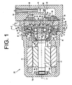
- FIG. 1 is a longitudinal cross-sectional view of the compressor of the first preferred embodiment.
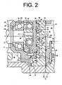
- FIG. 2 is a partially enlarged cross-sectional view of the compressor.
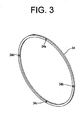
- FIG. 3 is a perspective view of an annular seal member.
- FIG. 4 is a cross-sectional view taken along the line I - I in FIG. 1.
- a compressor 10 has a housing 11 including a first housing component 12 and a second housing component 13 which is fixed to the first housing component 12.
- the first housing component 12 has a cylindrical shape which has a bottom 12a on the left side in FIG. 1.
- the second housing component 13 is cover-shaped and has a partition 13a which defines a plurality of spaces therein. The opening end of the first housing component 12 is covered with the second housing component 13.
- the first housing component 12 has an annular rib 12b which extends from the center of the inner surface of the bottom 12a.
- the first housing component 12 accommodates a shaft support 14 adjacently to the opening endof the first housing component 12.
- the shaft support 14 includes a cylindrical portion 15 and a flange portion 16.
- the cylindrical portion 15 has a hole 15a and a bearing-receiving portion 15b.
- the flange portion 16 extends radially from the right end of the cylindrical portion 15 adjacent to the opening of the first housing component 12.
- the outer periphery of the flange portion 16 is press-fitted to the inner wall of the first housing component 12.
- the inner space of the first housing component 12 is divided into two spaces by the shaft support 14.
- the first housing component 12 accommodates a rotary shaft 17.
- the rotary shaft 17 is rotatably supported at one end thereof by a bearing 18 which is disposed in the rib 12b, and at the other end thereof by a bearing 19 which is disposed in the bearing-receiving portion 15b of the shaft support 14.
- the inner space of the first housing component 12 adjacent to the bottom 12a provides a motor chamber 20 in which a stator 21 is fixed to the inner surface of the first housing component 12.
- a rotor 22 is disposed inside the stator 21 and fixed to the rotary shaft 17 in the motor chamber 20.
- the stator 21 and the rotor 22 form an electric motor of the compressor 10, and electric power is supplied to the stator 21 to rotate the rotor 22 and the rotary shaft 17 integrally.
- a fixed scroll member 25 is accommodated and fixed in the first housing component 12 adjacent to the opening of the first housing component 12 so that it is located closer to the opening of the first housing component 12 than the shaft support 14.
- a movable scroll member 35 is disposed between the fixed scroll member 25 and the shaft support 14.
- the fixed scroll member 25 has a disc-shaped fixed base plate 26, an outer peripheral wall 27 and a fixed scroll wall 28.
- the outer peripheral wall 27 extends from the outer periphery of a front surface (or a left surface in FIG. 1) of the fixed base plate 26.
- the fixed scroll wall 28 extends from the radially inner portion of the front surface of the fixed base plate 26 inside the outer peripheral wall 27.
- the surface of the fixed base plate 26 which faces the movable scroll member 35 is the front surface of the fixed base plate 26 or the fixed scroll member 25.
- a seal member 29 is provided on the distal end of the fixed scroll wall 28, and the outer peripheral wall 27 is joined at its distal end to the outer periphery of the flange portion 16 of the shaft support 14.
- a crankshaft 30 is provided on the end of the rotary shaft 17 adjacent to the opening of the first housing component 12 and has an eccentric axis Q which is offset from the axis P of the rotary shaft 17.
- a bushing 31 is fitted on the crankshaft 30.
- An inner ring of a bearing 32 is attached to the bushing 31.
- the movable scroll member 35 is supported on an outer ring of the bearing 32.
- a balancer 33 is provided on the bushing 31 for alleviating imbalance of the rotary shaft 17 due to the offset arrangement of the movable scroll member 35.
- the movable scroll member 35 has a disc-shaped movable base plate 36, an annular outer peripheral wall 37, a movable scroll wall 38, and a bearing-receiving portion 39 or a boss for receiving therein the bearing 32.
- the annular outer peripheral wall 37 extends from the outer periphery of a back surface (or a left surface in FIG. 1) of the movable base plate 36.
- the movable scroll wall 38 extends from a front surface (or a right surface in FIG 1) of the movable base plate 36 and is located radially inward of the outer peripheral wall 37.
- the surface of the movable base plate 36 which faces the fixed scroll member 25 is the front surface of the movable base plate 36 or the movable scroll member 35.
- a seal member 40 is provided on the distal end of the movable scroll wall 38.
- the outer peripheral wall 37 is in slide contact at the distal end thereof with the flange portion 16 of the shaft support 14.
- the shaft support 14 corresponds to a slide-contact body of the invention which is in slide contact with the back surface of the movable scroll member 35.
- An annular seal member 34 as a first seal member is provided on the distal end of the outer peripheral wall 37 of the movable scroll member 35. The seal member 34 will be described later.
- the movable scroll wall 38 of the movable scroll member 35 and the fixed scroll wall 28 of the fixed scroll member 25 are engaged with each other.
- the movable scroll wall 38 is in slide contact at the distal end thereof with the fixed base plate 26.
- the fixed scroll wall 28 is in slide contact at the distal end thereof with the movable base plate 36.
- the fixed scroll member 25 and the movable scroll member 35 cooperate to define therebetween compression chambers 41 by the base plates 26 and 36 and the scroll walls 28 and 38.
- a plurality of pins 42 as a self-rotation blocking means for the movable scroll member 35 are provided between the back surface of the movable base plate 36 and the flange portion 16 of the shaft support 14.
- the outer peripheral wall 27 of the fixed scroll member 25, the outer peripheral wall 37 of the movable scroll member 35 and the flange portion 16 of the shaft support 14 cooperate to define a suction chamber 43 as a suction-pressure region.
- the flange portion 16 of the shaft support 14 has a suction passage 44 which connects the motor chamber 20 to the suction chamber 43.
- the first housing component 12 has an inlet 45 which is in communication with the motor chamber 20 and is connected to the lower pressure side of an external refrigerant circuit.
- low-pressure refrigerant gas is introduced from the external refrigerant circuit into the suction chamber 43 through the inlet 45, the motor chamber 20 and the suction passage 44 during operation of the compressor 10.
- the motor chamber 20 and the suction chamber 43 also correspond to the suction-pressure region of the invention.
- a discharge chamber 48, an oil-separation chamber 49 and an oil-collection chamber 50 are defined in the second housing component 13 of the housing 11.
- the fixed scroll member 25 has at the center thereof a discharge hole 26a.
- a reed type valve 46 is provided on the fixed base plate 26 adjacent to the opening of the discharge hole 26a which faces the discharge chamber 48.
- a partition member 47 is disposed between the second housing component 13 and the fixed scroll member 25 and defines the discharge chamber 48 and the oil-collection chamber 50 together with the partition 13a.
- the discharge chamber 48, the oil-separation chamber 49 and the oil-collection chamber 50 are divided by the partition 13a.
- the partition 13a has a passage 51 which connects the discharge chamber 48 to the oil-separation chamber 49 and a passage 52 which connects the oil-separation chamber 49 to the oil-collection chamber 50.
- An oil separator 53 is provided in the oil-separation chamber 49 for collecting lubricating oil which is contained in the refrigerant gas having a discharge pressure.
- the oil separator 53 is connected to the high-pressure side of the external refrigerant circuit.
- the lubricating oil which is collected by the oil separator 53 is introduced into the oil-collection chamber 50 through the passage 52.
- the high-pressure compressed refrigerant gas is delivered to the external refrigerant circuit through the discharge hole 26a, the discharge chamber 48, the oil-separation chamber 49 and the oil separator 53.
- the discharge chamber 48, the oil-separation chamber 49 and the oil-collection chamber 50 correspond to the discharge-pressure region of the invention.
- the partition member 47 has a hole 55 extending therethrough from the oil-collection chamber 50 to the outer periphery of the back surface of the fixed base plate 26.
- the opening of the hole 55 adjacent to the oil-collection chamber 50 is covered with a filter 56 which serves to remove foreign substances from the lubricating oil flowing from the oil-collection chamber 50 into the hole 55.
- the fixed base plate 26 has at the outer periphery thereof a hole 57 which is in communication with the hole 55 and extends from the back surface to the front surface of the fixed base plate 26.
- the fixed base plate 26 has a front wall 26b radially inward of the outer peripheral wall 27.
- the hole 57 has an opening on the front wall 26b.
- the opening of the hole 57 in the front wall 26b faces the outer periphery of the front surface of the movable base plate 36 of the movable scroll member 35.
- the outer periphery of the front surface of the movable base plate 36 is in slide contact with the front wall 26b located on the outer periphery of the fixed base plate 26.
- a slight gap (clearance) is formed between the movable base plate 36 and the front wall 26b of the fixed base plate 26 and allows the movable scroll member 35 to slightly move in the direction of the axis P.
- tip seals 58 and 59 are provided on the front wall 26b of the fixed base plate 26 for sealing between the hole 57 and the suction chamber 43 and between the hole 57 and the compression chamber 41, respectively.
- the movable base plate 36 has a hole 60 which is extended through the movable base plate 36 at the outer periphery of the front surface which faces the front wall 26b.
- the hole 60 communicates the above gap (clearance) with the back surface of the movable base plate 36.
- One opening of the hole 60 is located at the front surface of the movable base plate 36, facing the front wall 26b of the fixed base plate 26.
- the other opening of the hole 60 opened on the back surface of the movable base plate 36 is located radially inward of the outer peripheral wall 37.
- a space surrounded by the outer peripheral wall 37 of the movable base plate 36 forms a back-pressure chamber 61 as a back-pressure region.
- the back-pressure chamber 61 is defined by the back surface of the movable base plate 36 and the inner wall surface of the shaft support 14.
- a shaft-seal member 62 is disposed in the shaft support 14 for sealing between the back-pressure chamber 61 and the motor chamber 20 and held by a retaining ring 63 which is fitted in the inner wall surface of the shaft support 14.
- an introduction passage includes the hole 55, the hole 57, the slight gap (clearance) between the front wall 26b of the fixed base plate 26 and the movable base plate 36, and the hole 60 to connect the oil-collection chamber 50 to the back-pressure chamber 61.
- the introduction passage is used for adjusting the back pressure by the discharge pressure.
- the seal member 34 is installed in a groove 37a which is formed in the distal end of the outer peripheral wall 37.
- the seal member 34 is made of rubber and has four groove portions 34a through 34d as first groove portions which are spaced at regular intervals along the circumference of the seal member 34, that is, at intervals each corresponding to one-fourth of the circumferential length of the seal member 34 as shown in FIG. 3.
- the groove portions are provided under the following conditions.
- the number of the groove portions is two or more.
- the groove portions two groove portions, whose direct distance therebetween is the longest, are selected, and the shortest distance along the circumference of the seal member 34 between the selected two groove portions (e.g. the groove portion 34c is the remotest from the groove portion 34a, and the groove portion 34d is the remotest from the groove portion 34b.) is set at not less than one-third of the circumferential length of the seal member 34.
- the longest distance along the circumference of the seal member 34 therebetween is set at not more than two-thirds of the circumferential length of the seal member 34.
- Each of the groove portions 34a through 34d is a narrow groove formed in the end surface of the seal member 34 and extending in the radial direction of the seal member 34 for connecting the back-pressure chamber 61 to the suction chamber 43.
- Each depth of the groove portions 34a through 34d corresponds to the width of the gap between the front wall 26b of the fixed base plate 26 and the movable base plate 36.
- Each width of the groove portions 34a through 34d is set so that the groove portions 34a through 34d function as a throttle between the back-pressure chamber 61 and the suction chamber 43.
- any of the groove portions 34a through 34d faces the upper area of the back-pressure chamber 61 and the suction chamber 43, and any groove portion other than the groove portion faces the lower area thereof. That is, there exist at least one groove which connects the upper areas of the back-pressure chamber 61 and the suction chamber 43, and at least one groove which connects the lower areas of the back-pressure chamber 61 and the suction chamber 43.
- the back pressure in the back-pressure chamber 61 can be set as intended.
- the seal member 34 may be moved in the groove 37a circumferentially.
- the upper areas of the back-pressure chamber 61 and the suction chamber 43 indicate areas corresponding to one-fourth of the vertical length of the compressor 10 from the top of the compressor 10 which is mounted horizontally.
- the lower areas of the back-pressure chamber 61 and the suction chamber 43 indicate areas corresponding to one-fourth of the vertical length of the compressor 10.
- the refrigerant is in gas state in the upper areas of the back-pressure chamber 61 and the suction chamber 43 where the groove portions 34a through 34d of the seal member 34 are hardly clogged with liquid.
- the refrigerant tends to be in mist state or liquid state in the lower areas of the back-pressure chamber 61 and the suction chamber 43.
- the lubricating oil tends to be accumulated therein.
- the groove portions 34a through 34d of the seal member 34 in the lower area tends to be clogged with liquid such as the refrigerant liquid and the lubricating oil.
- the compressor 10 When the electric motor of the compressor 10 is supplied with electric power, the rotor 22 is rotated with the rotary shaft 17. As the rotary shaft 17 is rotated, the movable scroll member 35 orbits while blocking its self rotation, thus drawing the refrigerant into the compression chambers 41 and compressing it therein.
- the low-pressure refrigerant is introduced from the external refrigerant circuit into the suction chamber 43 through the inlet 45, the motor chamber 20 and the suction passage 44.
- the refrigerant In the compression process, the refrigerant is compressed in the compression chamber 41 by volume reduction of the compression chamber 41.
- the compressed refrigerant pushes open the check valve 46 and is discharged to the external refrigerant circuit through the discharge hole 26a, the discharge chamber 48, the oil-separation chamber 49 and the oil separator 53.
- the lubricating oil contained in the refrigerant gas is separated in the oil separator 53 and collected in the oil-collection chamber 50.
- the oil-collection chamber 50 is a part of the discharge-pressure region, and the refrigerant in the oil-collection chamber 50 is introduced into the back-pressure chamber 61 through the introduction passage 55, 57, 60.
- the pressure (or back pressure) in the back-pressure chamber 61 depends on the balance between an amount of the refrigerant introduced from the oil-collection chamber 50 into the back-pressure chamber 61 through the introduction passage and an amount of the refrigerant flowing out of the back-pressure chamber 61 through the groove portions 34a through 34d.
- the movable scroll member 35 receives an urging force (or a back-pressure force) which results from the back pressure in the back-pressure chamber 61 and is applied thereto in the thrust direction (or in the direction of the axis P) to urge the movable scroll member 35 toward the fixed scroll member 25.
- the movable scroll member 35 also receives an urging force (or a compression force) which results from the refrigerant pressure in the compression chambers 41 and is applied thereto in the thrust direction to urge the movable scroll member 35 toward the shaft support 14.
- the back-pressure force and the compression force acts in opposite directions.
- the position of the movable scroll member 35 relative to the fixed scroll member 25 in the axial direction depends on the balance between the back-pressure force and the compression force (or a positive-pressure force).
- the movable base plate 36 of the movable scroll member 35 is moved away from the shaft support 14 by the back-pressure force. Thereby, the gap between the front wall 26b of the fixed base plate 26 and the movable scroll member 35 becomes minimum or the gap does not exist. As shown in FIG. 5A, when the gap between the front wall 26b and the movable base plate 36 is minimized, the introduction passage is closed to prevent the refrigerant gas from passing therethrough. Thus, the refrigerant gas having the discharge pressure is not introduced into the back-pressure chamber 61 from the oil-collection chamber 50 .
- a second gap is formed between the outer peripheral wall 37 of the movable base plate 36 and the shaft support 14. This second gap is formed by minimizing the gap between the fixed base plate 26 and the movable base plate 36 before the movable base plate 36 is moved away from the shaft support 14.
- the seal member 34 is provided between the outer peripheral wall 37 of the movable base plate 36 and the shaft support 14.
- the groove portions 34a through 34d connects the back-pressure chamber 61 to the suction chamber 43 even when there is no gap between the outer peripheral wall 37 of the movable base plate 36 and the shaft support 14. Since the pressure in the suction chamber 43 is lower than that in the back-pressure chamber 61, the refrigerant gas in the back-pressure chamber 61 flows out to the suction chamber 43 therethrough while being throttled by the groove portions 34a through 34d. Thus, the back pressure falls and the back-pressure force urging the movable scroll member 35 toward the fixed scroll member 25 is decreased.
- the atmosphere may be uneven between the upper and lower areas of the back-pressure chamber 61 and the suction chamber 43, for example, the atmosphere is in gas state in the upper area but is changed into liquid state in the lower area.
- any of the groove portions 34a through 34d which is located in the lower area may not function as a throttle due to liquid clogging, any other of the groove portions 34a through 34d which is located in the upper area functions as a throttle for adjusting the back pressure in the back-pressure chamber 61.
- a gap is formed between the front surface of the movable scroll member 35 and the front wall 26b of the fixed scroll member 25.
- the space or the gap as a part of the introduction passage is formed between the front surfaces of both scroll members 25 and 35 and defined by the tip seals 58 and 59.
- the refrigerant gas having the discharge pressure is introduced from the oil-collection chamber 50 into the back-pressure chamber 61 through the introduction passage.
- the back pressure in the back-pressure chamber 61 rises and the back-pressure force urging the movable scroll member 35 toward the fixed scroll member 25 is increased.
- the increased back-pressure force reduces the contact pressure between the outer peripheral wall 37 of the movable base plate 36 and the shaft support 14, and hence the frictional force of the movable base plate 36 relative to the shaft support 14 on the back side is reduced. As a result, power loss of the compressor 10 is reduced and the performance of the compressor 10 is improved.
- the increased back-pressure force establishes the stabler and closer contact between the movable scroll member 35 and the fixed scroll member 25 to prevent the refrigerant gas from leaking out of the compression chambers 41.
- compression efficiency of the compressor 10 is improved, which contributes to improving the performance of the compressor 10.
- the movable scroll member 35 changes the size of the gap between the front surface of the movable base plate 36 and the shaft support 14 so that the back-pressure force based on the back pressure in the back-pressure chamber 61 corresponds appropriately to the compression force based on the pressure in the compression chambers 41, thereby adjusting the back pressure in the back-pressure chamber 61.
- the sliding resistance due to the orbital motion of the movable scroll member 35 can be reduced, and the sealing performance of the compression chambers 41 can be increased to improve the compression efficiency of the compressor 10.
- the compressor 10 of the preferred embodiment offers the following advantageous effects.
- FIG. 6 is a partially enlarged cross-sectional view of the compressor of the second preferred embodiment.
- the basic structure of the compressor 70 of the second preferred embodiment is the same as that of the first preferred embodiment, and, therefore, the description of the structure of the compressor 70 common to the compressor 10 is not given.
- a cylindrical first housing component 72 with a bottom (not shown) is joined to a cover-like second housing component 73.
- a space in the first housing component 72 is divided by a shaft support 74, and a divided space in the first housing component 72 on the bottom side is a motor chamber 75.
- a fixed scroll member 76 is accommodated and fixed in the first housing component 72 adjacently to the opening end thereof.
- the fixed scroll member 76 includes a fixed base plate 77, a fixed scroll wall 78 extending from the front surface (or a left surface in FIG 6) of the fixed base plate 77, and an outer peripheral wall 79 extending from the outer periphery of the front surface of the fixed base plate 77.
- a discharge chamber 80 as a discharge-pressure region is defined in the second housing component 73 on the back side (or a right side in FIG 6) of the fixed base plate 77.
- a movable scroll member 81 is disposed between the fixed scroll member 76 and the shaft support 74.
- the shaft support 74 corresponds to a slide-contact body of the invention which is in slide contact with the back surface of the movable scroll member 81.
- the movable scroll member 81 is supported by a crankshaft (not shown) of a rotary shaft (not shown) so that it can be orbited.
- the movable scroll member 81 includes a movable base plate 82 and a movable scroll wall 83 extending from the front surface (or a right surface in FIG. 6) of the movable base plate 82.
- the movable scroll member 81 and the fixed scroll member 76 are engaged with each other thereby to define compression chambers 85 therebetween.
- a suction chamber 86 as a suction-pressure region is defined between the outer peripheral wall 79 of the fixed base plate 77 and the outer peripheral surface of the movable base plate 82.
- the suction chamber 86 is connected to the external refrigerant circuit through an inlet 96 which extends through the outer peripheral wall 79 and the first housing component 72.
- the distal end of the movable scroll wall 83 is in slide contact with the front surface of the fixed base plate 77, and a tip seal 87 is provided on the distal end of the movable scroll wall 83.
- the distal end of the fixed scroll wall 78 is in slide contact with the front surface of the movable base plate 82, and a tip seal 88 is provided on the distal end of the fixed scroll wall 78.
- the front wall 77a of the fixed base plate 77 has a recess 77b in which two tip seals 89 are provided at the radially inner and outer peripheries thereof, respectively.
- the outer periphery of the back surface of the movable base plate 82 which is located radially inward of the suction chamber 86, is in slide contact with the shaft support 74.
- the movable base plate 82 has at the outer periphery of the back surface thereof an annular recess 82a which provides a back-pressure chamber.
- the back surface of the movable base plate 82 and the shaft support 74 are in slide contact with each other on the radially inner and outer sides of the recess 82a or the back-pressure chamber, and an annular seal member 90 as a first seal member is provided on the back surface of the movable base plate 82 on the radially outer side of the recess 82a.
- the seal member 90 has a plurality of groove portions 90a (or narrow grooves) as first groove portions for connecting the recess 82a to the suction chamber 86.
- An annular seal member 91 as a second seal member is provided on the shaft support 74 on the radially inner side of the recess 82a.
- the seal member 91 has a plurality of groove portions 91 a (or narrow grooves) as second groove portions for connecting the recess 82a to the motor chamber 75. Both seal members 90 and 91 have the same structure as seal member 34 of the first preferred embodiment except the size of diameter.
- the fixed base plate 77 has a hole 92 for connecting the discharge chamber 80 to the recess 77b.
- the opening of the hole 92 on the discharge chamber 80 side is covered with a filter 94.
- the movable base plate 82 of the movable scroll member 81 has a hole 95 for connecting the recess 77b of the fixed base plate 77 to the recess 82a of the movable base plate 82. That is, an introduction passage which includes the hole 92 and the recess 77b of the fixed base plate 77 and the hole 95 of the movable base plate 82, is provided for connecting the discharge chamber 80 to the recess 82a.
- the movable scroll member 81 orbits while blocking its self rotation, thus drawing the refrigerant gas into the compression chambers 41and compressing it therein.
- the movable scroll member 81 receives an urging force (or a back-pressure force) which results from the back pressure in the back-pressure chamber or the recess 82a and is applied thereto in the thrust direction to urge the movable scroll member 81 toward the fixed scroll member 76.
- the movable scroll member 81 also receives an urging force (or a compression force) which result from the pressure of the refrigerant gas in the compression chambers 85, and is applied to thereto in the thrust direction to urge the movable scroll member 81 toward the shaft support 74.
- the movable base plate 82 of the movable scroll member 81 is moved away from the shaft support 74 by the back-pressure force. Thereby, the gap between the fixed base plate 77 and the movable base plate 82 becomes minimum or does not exist.
- the introduction passage is closed to prevent the refrigerant gas from passing therethrough.
- the refrigerant gas having the discharge pressure is not introduced into the recess 82a from the discharge chamber 80.
- a gap exists between the movable base plate 82 and the shaft support 74 and has the same width as the gap between the fixed base plate 77 and the movable base plate 82 before the movable base plate 82 is moved away from the shaft support 74.
- the seal member 90 is provided between the movable base plate 82 and the shaft support 74 on the radially outer side of the recess 82a, when the gap exists between the movable base plate 82 and the shaft support 74, only the groove portions 90a connect the recess 82a to the suction chamber 86.
- the groove portions 91a of the seal member 91 connects the recess 82a to a space which is in communication with the motor chamber 75.
- any of the groove portions 90a and 91a of the seal members 90 and 91 which is located in the lower area may not function as a throttle due to liquid clogging.
- any other of the groove portions 90a and 91 a which is located in the upper area function as a throttle for adjusting the back pressure in the recess 82a.
- the movable base plate 82 of the movable scroll member 81 is moved away from the fixed base plate 77 by the compression force.
- the movable base plate 82 is brought into contact with the shaft support 74, thereby preventing the refrigerant gas from flowing through between the outer peripheral wall of the movable base plate 82 and the shaft support 74.
- a gap exists between the front surface of the movable scroll member 81 and the front surface of the fixed scroll member 76.
- the gap as a part of the introduction passage is formed in the recess 77b between the front surfaces of the both scroll members 76 and 81 and defined by the tip seals 89, and the refrigerant gas having the discharge pressure is introduced into the recess 82a through the introduction passage.
- the back pressure in the recess 82a rises and the back-pressure force urging the movable scroll member 81 toward the fixed scroll member 76 is increased.
- the increased back-pressure force reduces the contact pressure between the outer peripheral wall of the movable base plate 82 and the shaft support 74 and hence the frictional force of the movable base plate 82 relative to the shaft support 74 on the back side is reduced.
- the increased back-pressure force establishes stable and close contact of the movable scroll member 81 with the fixed scroll member 76 to prevent the refrigerant gas from leaking out of the compression chambers 85.
- the compressor 70 of the second preferred embodiment offers the same advantageous effects as mentioned in the paragraph (1) in the first preferred embodiment.
- the recess 82a as a back-pressure region is formed between the seal members 90 and 91 having the groove portions 90a and 91a, the back pressure in the back-pressure chamber can be more reliably set as intended.
- an annular seal member 101 has three groove portions (narrow grooves) 101 a through 101 c which are spaced at regular intervals along the circumference of the seal member 101.
- a distance along the circumference of the seal member 101 between any two of groove portions 101 a through 101 c which are adjacent to each other is one-third of the circumferential length of the seal member 101.
- the groove portions 101a through 101c for example, when the groove portion 101a is located in the upper area, the groove portions 101b and 101c are located in the lower area. In this case, since the groove portion 101 a and the groove portions 101b and 101c are respectively located in the upper and lower areas, controlling the back pressure is less adversely affected by the uneven atmosphere in the back-pressure chamber and the suction chamber.
- an annular seal member 102 has five groove portions 102a through 102e.
- the groove portions 102a through 102e are spaced at irregular intervals along the circumference of the seal member 102.
- the shortest distance along the circumference of the seal member 102 between the groove portion 102a and the groove portion 102d which is the remotest from the groove portion 102a is set at not less than one-third of the circumferential length of the seal member 102.
- the groove portion 102e is located on the seal member 102 between the groove portions 102a and 102d, which corresponds to the longest distance between the groove portions 102a and 102d.
- any of the groove portions 102a through 102e is located in the upper area of the back-pressure chamber and the suction chamber, and any other of them is located in the lower area thereof.
- an annular seal member 103 has two groove portions 103a and 103b. Both of the shortest and longest distances along the circumference of the seal member 103 between the groove portions 103a and 103b are set at not less than one-third of the circumferential length of the seal member 103.
- the groove portion 103a is located in the lower area of the back-pressure chamber and the suction chamber
- the groove portion 103b is located in the upper area thereof.
- both groove portions 103a and 103b are located at the substantially same height, namely, at the substantially same height as the center of the compressor. In this case, the groove portions 103a and 103b are not located in the lower area.
- the groove portions 103a and 103b are hardly clogged with liquid and mist, with the result that controlling the back pressure is hardly adversely affected by the uneven atmosphere in the back-pressure chamber and the suction chamber.
- the shortest and longest distance along the circumference of the seal members 101 through 103 between any two of the groove portions 101a through 101c, 102a through 102e or 103a and 103b which are the remotest from each other may be set at not less than one-third of the circumferential length of the seal member 101, 102 or 103.
- the number of the groove portions may be three or more, and the shortest distance along the circumference of the seal member between any two of the groove portions which are the remotest from each other, may be set at not less than one-third of the circumferential length of the seal member, and the rest of the groove portions may be located between the two of the groove portions on the part of the circumference of the seal member which corresponds to the longest distance along the circumference of the seal member therebetween.
- each of the groove portion 34a through 34d includes only a single narrow groove in the seal member 34.
- a seal member 105 has a groove portion 105c including a set of three narrow grooves 105a which extend radially or substantially parallely, and are spaced at certain intervals.
- Contact surfaces 105b which are in contact with the shaft support are formed between the narrow grooves 105a.
- the width of the groove portion 105c can be changed freely while the rigidity of the seal member 105 adjacent to the narrow grooves 105a is maintained.
- the cross section of the narrow grooves of the groove portion is not limited to a square shape but may be a circular shape, a triangular shape and the like as long as they function as a groove.
- the present invention is not limited to the first and second preferred embodiments described above and the alternative embodiments described above but may be modified as exemplified below.
- the annular seal member has the four groove portions which are spaced at regular intervals along the circumference of the annular seal member.
- the annular seal members as shown in FIGS. 7A through 7C may be used instead.
- the annular seal member is provided on the radially inner side of the recess formed on the front wall of the fixed base plate.
- a tip seal which does not have any groove portion may be provided in place of this annular seal member.
- only the other annular seal member which has the groove portions and is provided on the radially outer side of the recess is used for adjusting the back pressure by connecting the back-pressure chamber to the suction chamber.
- the two seal members which are provided on the radially inner and outer sides of the recess may have different structure. For example, the number of the groove portions and the number of the narrow grooves of each groove portion may be different between the two seal members.
- the shaft-seal member is provided for sealing between the back-pressure chamber and the motor chamber which is a part of the suction-pressure region.
- the shaft-seal member may not be provided and the motor chamber may be a part of the back-pressure region.
- the inlet is not connected to the motor chamber, and the suction passage needs to be provided so as to connect the inlet to the suction chamber.
- the oil separator is provided for collecting the lubricating oil in the refrigerant gas, and the collected lubricating oil is introduced into the back-pressure chamber through the introduction passage and flows through the groove portions of the annular seal member.
- another passage may be provided independently of the introduction passage for the lubricating oil to pass therethrough.
- the groove portions of the seal member can be less clogged with liquid.
Landscapes
- Engineering & Computer Science (AREA)
- Mechanical Engineering (AREA)
- General Engineering & Computer Science (AREA)
- Rotary Pumps (AREA)
- Applications Or Details Of Rotary Compressors (AREA)
Abstract
Description
- The present invention relates to a horizontally-mounted scroll compressor in which a crankshaft of an orbital scroll member extends horizontally, for example, a horizontally-mounted scroll compressor for compressing refrigerant for use in the refrigerant circuit of an air conditioning system.
- Conventional horizontally-mounted scroll compressors include a fixed scroll member having a fixed base plate which is fixed in the housing thereof and a fixed scroll wall which extends from the front surface of the fixed base plate, and a movable scroll member having a movable base plate and a movable scroll wall which extends from the front surface of the movable base plate. The fixed and movable scroll walls are engaged with each other thereby to define compression chambers therebetween. In such scroll compressor, the fixed base plate has a front wall which is in slide contact with the front surface of the movable scroll member. A shaft support is provided so as to slide relative to the back surface of the movable scroll member, and a back-pressure region is defined on the back side of the movable scroll member. The compression chambers are moved radially inwardly while being reduced in volume by the orbital motion of the movable scroll member, thereby the scroll compressor compressing a compressible fluid.
- In such scroll compressor, the movable scroll member receives a force (or a positive-pressure force) which results from the pressure in the compression chambers and is applied thereto in the thrust direction. As the pressure in the compression chambers rises, the positive-pressure force is increased. Thus, large load acts on the sliding portions of the movable scroll member, and the reliability of the scroll compressor may be damaged.
-
Japanese Patent Application Publication No. 2005-180345 - For example, when the pressure in the compression chambers falls, and the positive-pressure force applied to the movable scroll member becomes lower than a back-pressure force which results from the pressure in the back-pressure chamber and acts in the thrust direction. Thereby, the movable scroll member is moved toward the front wall of the fixed base plate. Thus, the clearance at the sliding portion between the movable scroll member and the front wall of the fixed scroll member becomes minimum, thereby preventing the refrigerant gas from being introduced from the discharge-pressure region to the back-pressure region. As a result, the pressure in the back-pressure chamber tends to fall.
- On the other hand, when the pressure in the compression chambers rises and the positive-pressure force applied to the movable scroll member exceeds the back-pressure force, the movable scroll member is moved away from the front wall of the fixed scroll member. Thus, the clearance between the movable scroll member and the front wall of the fixed scroll member becomes maximum, thereby promoting the refrigerant gas to be introduced from the discharge-pressure region to the back-pressure region therethrough. As a result, the pressure in the back-pressure region tends to rise.
- As to another conventional art,
Japanese Patent Application Publication No. 8-121366 - In the horizontally-mounted scroll compressor of
Japanese Patent Application Publication No. 2005-180345 - A passage may be provided between the back-pressure region and the suction-pressure region for controlling the back pressure. When the passage is located only at the lower area or adjacent to the lower area of the above regions, however, the passage may be clogged with liquid such as lubricating oil, refrigerant liquid or the like. Thus, frictional force at the sliding portion may be increased, and poor compression is caused. Therefore, when the atmosphere in the back-pressure region and the suction-pressure region is uneven, an intended back pressure may not be set in the conventional horizontally-mounted scroll compressor.
- The scroll compressor of
Japanese Patent Application Publication No. 8-121366 Japanese Patent Application Publication No. 8-121366 - The present invention is directed to a horizontally-mounted scroll compressor which provides an intended back pressure in a back-pressure region when the atmosphere in each of a back-pressure region and a suction-pressure region is uneven.
- In accordance with an aspect of the present invention, a horizontally-mounted scroll compressor which includes a housing, a fixed scroll member, a movable scroll member, a compression chamber, a slide-contact body, and a back-pressure region. The housing has a discharge-pressure region and a suction-pressure region. The fixed scroll member has a fixed base plate which is fixed in the housing and a fixed scroll wall which extends from a front surface of the fixed base plate. The movable scroll member has a movable base plate and a movable scroll wall which extends from a front surface of the movable base plate. The fixed and movable scroll walls are engaged with each other. The compression chamber is formed between the fixed and the movable scroll members. The compression chamber is moved radially inwardly while being reduced in volume by orbital motion of the movable scroll member thereby to compress a compressible fluid. The slide-contact body is provided so as to be in slide contact with a back surface of the movable base plate. The back-pressure region is defined in the housing on a back side of the movable base plate and connected to the discharge-pressure region through an introduction passage. A first annular seal member is provided between the movable base plate and the slide-contact body for sealing between the back-pressure region and the suction-pressure region. The first seal member has a plurality of first groove portions which connect the back-pressure region to the suction-pressure region. The shortest distance along a circumference of the first seal member between any two of the first groove portions which are the remotest from each other is set at not less than one-third of a circumferential length of the first seal member.
- Other aspects and advantages of the invention will become apparent from the following description, taken in conjunction with the accompanying drawings, illustrating by way of example the principles of the invention.
- The features of the present invention that are believed to be novel are set forth with particularity in the appended claims. The invention together with objects and advantages thereof, may best be understood by reference to the following description of the presently preferred embodiments together with the accompanying drawings in which:
- FIG. 1 is a longitudinal cross-sectional view of a horizontally-mounted scroll compressor of a first preferred embodiment according to the present invention;
- FIG. 2 is a partially enlarged cross-sectional view of the horizontally-mounted scroll compressor of the first preferred embodiment;
- FIG. 3 is a perspective view of a seal member of the first preferred embodiment;
- FIG. 4 is a cross-sectional view taken along the line I - I in FIG. 1;
- FIG. 5A is a partially enlarged cross-sectional view of the horizantally-maunted scroll compressor of the first preferred embodiment when a gap exists between a movable base plate and a shaft support;
- FIG. 5B is a partially enlarged cross-sectional view of the horizontally-mounted scroll compressor of the first preferred embodiment when a gap exists between the movable base plate and a fixed base plate;
- FIG. 6 is a partially enlarged cross-sectional view of a horizontally-mounted scroll compressor of a second preferred embodiment according to the present invention;
- FIG. 7A is a front view of an annular seal member of an alternative embodiment according to the present invention;
- FIG. 7B is a front view of an annular seal member of an alternative embodiment according to the present invention;
- FIG. 7C is a front view of an annular seal member of an alternative embodiment according to the present invention; and
- FIG. 8 is a perspective view of a groove portion of an annular seal member of an alternative embodiment according to the present invention.
- The following will describe a horizontally-mounted scroll compressor of a first preferred embodiment according to the present invention. The horizontally-mounted scroll compressor is used in the refrigerant circuit of a vehicle air conditioning system and hereinafter referred to merely as compressor. Carbon dioxide is used as a compressible fluid in the refrigerant circuit. FIG. 1 is a longitudinal cross-sectional view of the compressor of the first preferred embodiment. FIG. 2 is a partially enlarged cross-sectional view of the compressor. FIG. 3 is a perspective view of an annular seal member. FIG. 4 is a cross-sectional view taken along the line I - I in FIG. 1.
- Referring to FIG. 1, a
compressor 10 has ahousing 11 including afirst housing component 12 and asecond housing component 13 which is fixed to thefirst housing component 12. Thefirst housing component 12 has a cylindrical shape which has a bottom 12a on the left side in FIG. 1. Thesecond housing component 13 is cover-shaped and has apartition 13a which defines a plurality of spaces therein. The opening end of thefirst housing component 12 is covered with thesecond housing component 13. - The
first housing component 12 has anannular rib 12b which extends from the center of the inner surface of the bottom 12a. Thefirst housing component 12 accommodates ashaft support 14 adjacently to the opening endof thefirst housing component 12. Theshaft support 14 includes acylindrical portion 15 and aflange portion 16. Thecylindrical portion 15 has ahole 15a and a bearing-receivingportion 15b. Theflange portion 16 extends radially from the right end of thecylindrical portion 15 adjacent to the opening of thefirst housing component 12. The outer periphery of theflange portion 16 is press-fitted to the inner wall of thefirst housing component 12. Thus, the inner space of thefirst housing component 12 is divided into two spaces by theshaft support 14. - The
first housing component 12 accommodates arotary shaft 17. Therotary shaft 17 is rotatably supported at one end thereof by a bearing 18 which is disposed in therib 12b, and at the other end thereof by a bearing 19 which is disposed in the bearing-receivingportion 15b of theshaft support 14. The inner space of thefirst housing component 12 adjacent to the bottom 12a provides amotor chamber 20 in which astator 21 is fixed to the inner surface of thefirst housing component 12. Arotor 22 is disposed inside thestator 21 and fixed to therotary shaft 17 in themotor chamber 20. Thestator 21 and therotor 22 form an electric motor of thecompressor 10, and electric power is supplied to thestator 21 to rotate therotor 22 and therotary shaft 17 integrally. - A fixed
scroll member 25 is accommodated and fixed in thefirst housing component 12 adjacent to the opening of thefirst housing component 12 so that it is located closer to the opening of thefirst housing component 12 than theshaft support 14. Amovable scroll member 35 is disposed between thefixed scroll member 25 and theshaft support 14. The fixedscroll member 25 has a disc-shaped fixedbase plate 26, an outerperipheral wall 27 and a fixedscroll wall 28. The outerperipheral wall 27 extends from the outer periphery of a front surface (or a left surface in FIG. 1) of the fixedbase plate 26. The fixedscroll wall 28 extends from the radially inner portion of the front surface of the fixedbase plate 26 inside the outerperipheral wall 27. In this invention, the surface of the fixedbase plate 26 which faces themovable scroll member 35 is the front surface of the fixedbase plate 26 or the fixedscroll member 25. Aseal member 29 is provided on the distal end of the fixedscroll wall 28, and the outerperipheral wall 27 is joined at its distal end to the outer periphery of theflange portion 16 of theshaft support 14. - A
crankshaft 30 is provided on the end of therotary shaft 17 adjacent to the opening of thefirst housing component 12 and has an eccentric axis Q which is offset from the axis P of therotary shaft 17. Abushing 31 is fitted on thecrankshaft 30. An inner ring of abearing 32 is attached to thebushing 31. Themovable scroll member 35 is supported on an outer ring of thebearing 32. Abalancer 33 is provided on thebushing 31 for alleviating imbalance of therotary shaft 17 due to the offset arrangement of themovable scroll member 35. - The
movable scroll member 35 has a disc-shapedmovable base plate 36, an annular outerperipheral wall 37, amovable scroll wall 38, and a bearing-receivingportion 39 or a boss for receiving therein thebearing 32. The annular outerperipheral wall 37 extends from the outer periphery of a back surface (or a left surface in FIG. 1) of themovable base plate 36. Themovable scroll wall 38 extends from a front surface (or a right surface in FIG 1) of themovable base plate 36 and is located radially inward of the outerperipheral wall 37. In this invention, the surface of themovable base plate 36 which faces the fixedscroll member 25 is the front surface of themovable base plate 36 or themovable scroll member 35. Aseal member 40 is provided on the distal end of themovable scroll wall 38. The outerperipheral wall 37 is in slide contact at the distal end thereof with theflange portion 16 of theshaft support 14. Theshaft support 14 corresponds to a slide-contact body of the invention which is in slide contact with the back surface of themovable scroll member 35. Anannular seal member 34 as a first seal member is provided on the distal end of the outerperipheral wall 37 of themovable scroll member 35. Theseal member 34 will be described later. - The
movable scroll wall 38 of themovable scroll member 35 and the fixedscroll wall 28 of the fixedscroll member 25 are engaged with each other. Themovable scroll wall 38 is in slide contact at the distal end thereof with the fixedbase plate 26. The fixedscroll wall 28 is in slide contact at the distal end thereof with themovable base plate 36. Thus, the fixedscroll member 25 and themovable scroll member 35 cooperate to definetherebetween compression chambers 41 by thebase plates scroll walls pins 42 as a self-rotation blocking means for themovable scroll member 35 are provided between the back surface of themovable base plate 36 and theflange portion 16 of theshaft support 14. - The outer
peripheral wall 27 of the fixedscroll member 25, the outerperipheral wall 37 of themovable scroll member 35 and theflange portion 16 of theshaft support 14 cooperate to define asuction chamber 43 as a suction-pressure region. Theflange portion 16 of theshaft support 14 has asuction passage 44 which connects themotor chamber 20 to thesuction chamber 43. Thefirst housing component 12 has aninlet 45 which is in communication with themotor chamber 20 and is connected to the lower pressure side of an external refrigerant circuit. Thus, low-pressure refrigerant gas is introduced from the external refrigerant circuit into thesuction chamber 43 through theinlet 45, themotor chamber 20 and thesuction passage 44 during operation of thecompressor 10. In the first preferred embodiment, themotor chamber 20 and thesuction chamber 43 also correspond to the suction-pressure region of the invention. - A
discharge chamber 48, an oil-separation chamber 49 and an oil-collection chamber 50 are defined in thesecond housing component 13 of thehousing 11. The fixedscroll member 25 has at the center thereof adischarge hole 26a. Areed type valve 46 is provided on the fixedbase plate 26 adjacent to the opening of thedischarge hole 26a which faces thedischarge chamber 48. In the first preferred embodiment, apartition member 47 is disposed between thesecond housing component 13 and the fixedscroll member 25 and defines thedischarge chamber 48 and the oil-collection chamber 50 together with thepartition 13a. Thedischarge chamber 48, the oil-separation chamber 49 and the oil-collection chamber 50 are divided by thepartition 13a. Thepartition 13a has apassage 51 which connects thedischarge chamber 48 to the oil-separation chamber 49 and apassage 52 which connects the oil-separation chamber 49 to the oil-collection chamber 50. - An
oil separator 53 is provided in the oil-separation chamber 49 for collecting lubricating oil which is contained in the refrigerant gas having a discharge pressure. Theoil separator 53 is connected to the high-pressure side of the external refrigerant circuit. The lubricating oil which is collected by theoil separator 53 is introduced into the oil-collection chamber 50 through thepassage 52. During the operation of thecompressor 10, the high-pressure compressed refrigerant gas is delivered to the external refrigerant circuit through thedischarge hole 26a, thedischarge chamber 48, the oil-separation chamber 49 and theoil separator 53. Thedischarge chamber 48, the oil-separation chamber 49 and the oil-collection chamber 50 correspond to the discharge-pressure region of the invention. - The following will describe the adjustment of the back pressure acting on the
movable scroll member 35. As shown in FIG. 2, thepartition member 47 has ahole 55 extending therethrough from the oil-collection chamber 50 to the outer periphery of the back surface of the fixedbase plate 26. The opening of thehole 55 adjacent to the oil-collection chamber 50 is covered with afilter 56 which serves to remove foreign substances from the lubricating oil flowing from the oil-collection chamber 50 into thehole 55. The fixedbase plate 26 has at the outer periphery thereof ahole 57 which is in communication with thehole 55 and extends from the back surface to the front surface of the fixedbase plate 26. The fixedbase plate 26 has afront wall 26b radially inward of the outerperipheral wall 27. Thehole 57 has an opening on thefront wall 26b. - The opening of the
hole 57 in thefront wall 26b faces the outer periphery of the front surface of themovable base plate 36 of themovable scroll member 35. The outer periphery of the front surface of themovable base plate 36 is in slide contact with thefront wall 26b located on the outer periphery of the fixedbase plate 26. A slight gap (clearance) is formed between themovable base plate 36 and thefront wall 26b of the fixedbase plate 26 and allows themovable scroll member 35 to slightly move in the direction of the axis P. As shown in FIG. 2, tip seals 58 and 59 are provided on thefront wall 26b of the fixedbase plate 26 for sealing between thehole 57 and thesuction chamber 43 and between thehole 57 and thecompression chamber 41, respectively. - The
movable base plate 36 has ahole 60 which is extended through themovable base plate 36 at the outer periphery of the front surface which faces thefront wall 26b. Thehole 60 communicates the above gap (clearance) with the back surface of themovable base plate 36. One opening of thehole 60 is located at the front surface of themovable base plate 36, facing thefront wall 26b of the fixedbase plate 26. The other opening of thehole 60 opened on the back surface of themovable base plate 36 is located radially inward of the outerperipheral wall 37. A space surrounded by the outerperipheral wall 37 of themovable base plate 36 forms a back-pressure chamber 61 as a back-pressure region. The back-pressure chamber 61 is defined by the back surface of themovable base plate 36 and the inner wall surface of theshaft support 14. A shaft-seal member 62 is disposed in theshaft support 14 for sealing between the back-pressure chamber 61 and themotor chamber 20 and held by a retainingring 63 which is fitted in the inner wall surface of theshaft support 14. - As described above, an introduction passage includes the
hole 55, thehole 57, the slight gap (clearance) between thefront wall 26b of the fixedbase plate 26 and themovable base plate 36, and thehole 60 to connect the oil-collection chamber 50 to the back-pressure chamber 61. The introduction passage is used for adjusting the back pressure by the discharge pressure. - The foregoing has described that the distal end of the outer
peripheral wall 37 of themovable scroll member 35 is in slide contact with theflange portion 16 of theshaft support 14, and theseal member 34 is provided thereon. Theseal member 34 is installed in agroove 37a which is formed in the distal end of the outerperipheral wall 37. Theseal member 34 is made of rubber and has fourgroove portions 34a through 34d as first groove portions which are spaced at regular intervals along the circumference of theseal member 34, that is, at intervals each corresponding to one-fourth of the circumferential length of theseal member 34 as shown in FIG. 3. Preferably, the groove portions are provided under the following conditions. The number of the groove portions is two or more. Among the groove portions, two groove portions, whose direct distance therebetween is the longest, are selected, and the shortest distance along the circumference of theseal member 34 between the selected two groove portions (e.g. thegroove portion 34c is the remotest from thegroove portion 34a, and thegroove portion 34d is the remotest from thegroove portion 34b.) is set at not less than one-third of the circumferential length of theseal member 34. The longest distance along the circumference of theseal member 34 therebetween is set at not more than two-thirds of the circumferential length of theseal member 34. Each of thegroove portions 34a through 34d is a narrow groove formed in the end surface of theseal member 34 and extending in the radial direction of theseal member 34 for connecting the back-pressure chamber 61 to thesuction chamber 43. Each depth of thegroove portions 34a through 34d corresponds to the width of the gap between thefront wall 26b of the fixedbase plate 26 and themovable base plate 36. Each width of thegroove portions 34a through 34d is set so that thegroove portions 34a through 34d function as a throttle between the back-pressure chamber 61 and thesuction chamber 43. - When the
seal member 34 thus formed is installed in themovable scroll member 35, any of thegroove portions 34a through 34d faces the upper area of the back-pressure chamber 61 and thesuction chamber 43, and any groove portion other than the groove portion faces the lower area thereof. That is, there exist at least one groove which connects the upper areas of the back-pressure chamber 61 and thesuction chamber 43, and at least one groove which connects the lower areas of the back-pressure chamber 61 and thesuction chamber 43. When the atmosphere in the back-pressure chamber 61 and thesuction chamber 43 is uneven, the back pressure is adjusted through thegroove portions groove portions 34a is located on the upper side where clogging hardly occurs, and thegroove portions pressure chamber 61 can be set as intended. When themovable scroll member 35 orbits in slide contact with theshaft support 14, theseal member 34 may be moved in thegroove 37a circumferentially. Despite such movement of theseal member 34, there exist at least one of thegroove portions 34a through 34d which connects the upper areas of the back-pressure chamber 61 and thesuction chamber 43, and at least one of thegroove portions 34a through 34d which connects the lower areas of the back-pressure chamber 61 and thesuction chamber 43. - In the first preferred embodiment, the upper areas of the back-
pressure chamber 61 and thesuction chamber 43 indicate areas corresponding to one-fourth of the vertical length of thecompressor 10 from the top of thecompressor 10 which is mounted horizontally. The lower areas of the back-pressure chamber 61 and thesuction chamber 43 indicate areas corresponding to one-fourth of the vertical length of thecompressor 10. The refrigerant is in gas state in the upper areas of the back-pressure chamber 61 and thesuction chamber 43 where thegroove portions 34a through 34d of theseal member 34 are hardly clogged with liquid. The refrigerant tends to be in mist state or liquid state in the lower areas of the back-pressure chamber 61 and thesuction chamber 43. In addition, the lubricating oil tends to be accumulated therein. Thus, thegroove portions 34a through 34d of theseal member 34 in the lower area tends to be clogged with liquid such as the refrigerant liquid and the lubricating oil. - The following will describe the operation of the
compressor 10. When the electric motor of thecompressor 10 is supplied with electric power, therotor 22 is rotated with therotary shaft 17. As therotary shaft 17 is rotated, themovable scroll member 35 orbits while blocking its self rotation, thus drawing the refrigerant into thecompression chambers 41 and compressing it therein. In the suction process, the low-pressure refrigerant is introduced from the external refrigerant circuit into thesuction chamber 43 through theinlet 45, themotor chamber 20 and thesuction passage 44. In the compression process, the refrigerant is compressed in thecompression chamber 41 by volume reduction of thecompression chamber 41. The compressed refrigerant pushes open thecheck valve 46 and is discharged to the external refrigerant circuit through thedischarge hole 26a, thedischarge chamber 48, the oil-separation chamber 49 and theoil separator 53. The lubricating oil contained in the refrigerant gas is separated in theoil separator 53 and collected in the oil-collection chamber 50. - The oil-
collection chamber 50 is a part of the discharge-pressure region, and the refrigerant in the oil-collection chamber 50 is introduced into the back-pressure chamber 61 through theintroduction passage pressure chamber 61 depends on the balance between an amount of the refrigerant introduced from the oil-collection chamber 50 into the back-pressure chamber 61 through the introduction passage and an amount of the refrigerant flowing out of the back-pressure chamber 61 through thegroove portions 34a through 34d. - The
movable scroll member 35 receives an urging force (or a back-pressure force) which results from the back pressure in the back-pressure chamber 61 and is applied thereto in the thrust direction (or in the direction of the axis P) to urge themovable scroll member 35 toward the fixedscroll member 25. Themovable scroll member 35 also receives an urging force (or a compression force) which results from the refrigerant pressure in thecompression chambers 41 and is applied thereto in the thrust direction to urge themovable scroll member 35 toward theshaft support 14. The back-pressure force and the compression force acts in opposite directions. Thus, the position of themovable scroll member 35 relative to the fixedscroll member 25 in the axial direction depends on the balance between the back-pressure force and the compression force (or a positive-pressure force). - When the pressure in the
compression chamber 41 falls and the compression force becomes lower than the back-pressure force, themovable base plate 36 of themovable scroll member 35 is moved away from theshaft support 14 by the back-pressure force. Thereby, the gap between thefront wall 26b of the fixedbase plate 26 and themovable scroll member 35 becomes minimum or the gap does not exist. As shown in FIG. 5A, when the gap between thefront wall 26b and themovable base plate 36 is minimized, the introduction passage is closed to prevent the refrigerant gas from passing therethrough. Thus, the refrigerant gas having the discharge pressure is not introduced into the back-pressure chamber 61 from the oil-collection chamber 50 . By moving themovable base plate 36 away from theshaft support 14, however, a second gap is formed between the outerperipheral wall 37 of themovable base plate 36 and theshaft support 14. This second gap is formed by minimizing the gap between the fixedbase plate 26 and themovable base plate 36 before themovable base plate 36 is moved away from theshaft support 14. - The
seal member 34 is provided between the outerperipheral wall 37 of themovable base plate 36 and theshaft support 14. Thus, thegroove portions 34a through 34d connects the back-pressure chamber 61 to thesuction chamber 43 even when there is no gap between the outerperipheral wall 37 of themovable base plate 36 and theshaft support 14. Since the pressure in thesuction chamber 43 is lower than that in the back-pressure chamber 61, the refrigerant gas in the back-pressure chamber 61 flows out to thesuction chamber 43 therethrough while being throttled by thegroove portions 34a through 34d. Thus, the back pressure falls and the back-pressure force urging themovable scroll member 35 toward the fixedscroll member 25 is decreased. At this time, the atmosphere may be uneven between the upper and lower areas of the back-pressure chamber 61 and thesuction chamber 43, for example, the atmosphere is in gas state in the upper area but is changed into liquid state in the lower area. In this case, even if any of thegroove portions 34a through 34d which is located in the lower area may not function as a throttle due to liquid clogging, any other of thegroove portions 34a through 34d which is located in the upper area functions as a throttle for adjusting the back pressure in the back-pressure chamber 61. - When the pressure in the
compression chambers 41 rises and the compression force exceeds the back-pressure force, themovable base plate 36 of themovable scroll member 35 is moved away from the fixedbase plate 26 by the compression force. Thus, as shown in FIG. 5B, the outerperipheral wall 37 of themovable base plate 36 is brought into contact with theshaft support 14, thereby preventing the refrigerant gas from flowing through between the outerperipheral wall 37 of themovable base plate 36 and theshaft support 14. - A gap is formed between the front surface of the
movable scroll member 35 and thefront wall 26b of the fixedscroll member 25. The space or the gap as a part of the introduction passage is formed between the front surfaces of bothscroll members collection chamber 50 into the back-pressure chamber 61 through the introduction passage. Thus, the back pressure in the back-pressure chamber 61 rises and the back-pressure force urging themovable scroll member 35 toward the fixedscroll member 25 is increased. The increased back-pressure force reduces the contact pressure between the outerperipheral wall 37 of themovable base plate 36 and theshaft support 14, and hence the frictional force of themovable base plate 36 relative to theshaft support 14 on the back side is reduced. As a result, power loss of thecompressor 10 is reduced and the performance of thecompressor 10 is improved. - The increased back-pressure force establishes the stabler and closer contact between the
movable scroll member 35 and the fixedscroll member 25 to prevent the refrigerant gas from leaking out of thecompression chambers 41. Thus, compression efficiency of thecompressor 10 is improved, which contributes to improving the performance of thecompressor 10. - As described above, the
movable scroll member 35 changes the size of the gap between the front surface of themovable base plate 36 and theshaft support 14 so that the back-pressure force based on the back pressure in the back-pressure chamber 61 corresponds appropriately to the compression force based on the pressure in thecompression chambers 41, thereby adjusting the back pressure in the back-pressure chamber 61. Thus, the sliding resistance due to the orbital motion of themovable scroll member 35 can be reduced, and the sealing performance of thecompression chambers 41 can be increased to improve the compression efficiency of thecompressor 10. - The
compressor 10 of the preferred embodiment offers the following advantageous effects. - (1) The
seal member 34 serves to seal between the back-pressure chamber 61 and thesuction chamber 43 while thegroove portion 34a through 34d of theseal member 34 connects the back-pressure chamber 61 to thesuction chamber 43. Thegroove portions 34a through 34d function as a throttle, and the refrigerant gas in the back-pressure chamber 61 flows therethrough into thesuction chamber 43 in which the pressure is lower than that in the back-pressure region. Thus, the back pressure in the back-pressure chamber 61 is adjusted in response to the discharge pressure. Since a plurality of thegroove portions 34a through 34d are formed in theseal member 34, any of thegroove portions 34a through 34d appropriately functions as a throttle even when the atmosphere in the back-pressure chamber 61 and thesuction chamber 43 is uneven. For example, when the atmosphere in the back-pressure chamber 61 and thesuction chamber 43 is in gas state in the upper area and is in liquid state in the lower area, any of thegroove portions 34a through 34d which is located in the lower area may be clogged with liquid. Even in this case, any other of thegroove portions 34a through 34d which is located in the upper area in which gas exists functions as a throttle. Thus, the back pressure in the back-pressure chamber 61 is appropriately adjusted. - (2) The lubricating oil which is separated by the
oil separator 53 is stored in the discharge-pressure region. Thus, the atmosphere in the back-pressure chamber 61 and the suction chamber tends to be uneven. In this situation, it is more advantageous when the back pressure in the back-pressure chamber 61 is set as intended. - (3) The back pressure in the back-
pressure chamber 61 can be adjusted merely by using simply theseal member 34 having thegroove portions 34a through 34d. In addition, theseal member 34 has simple structure and is easily manufactured. - The following will describe a compressor of a second preferred embodiment according to the present invention with reference to FIG. 6. The compressor of the second preferred embodiment is a horizontally-mounted scroll compressor similar to that of the first preferred embodiment. In the compressor of the second preferred embodiment, the back-pressure chamber is defined only by the movable scroll member and the shaft support. FIG. 6 is a partially enlarged cross-sectional view of the compressor of the second preferred embodiment.
- The basic structure of the
compressor 70 of the second preferred embodiment is the same as that of the first preferred embodiment, and, therefore, the description of the structure of thecompressor 70 common to thecompressor 10 is not given. Referring to FIG. 6, a cylindricalfirst housing component 72 with a bottom (not shown) is joined to a cover-likesecond housing component 73. A space in thefirst housing component 72 is divided by ashaft support 74, and a divided space in thefirst housing component 72 on the bottom side is amotor chamber 75. - A fixed
scroll member 76 is accommodated and fixed in thefirst housing component 72 adjacently to the opening end thereof. The fixedscroll member 76 includes a fixedbase plate 77, a fixedscroll wall 78 extending from the front surface (or a left surface in FIG 6) of the fixedbase plate 77, and an outerperipheral wall 79 extending from the outer periphery of the front surface of the fixedbase plate 77. Adischarge chamber 80 as a discharge-pressure region is defined in thesecond housing component 73 on the back side (or a right side in FIG 6) of the fixedbase plate 77. Amovable scroll member 81 is disposed between thefixed scroll member 76 and theshaft support 74. Theshaft support 74 corresponds to a slide-contact body of the invention which is in slide contact with the back surface of themovable scroll member 81. - The
movable scroll member 81 is supported by a crankshaft (not shown) of a rotary shaft (not shown) so that it can be orbited. Themovable scroll member 81 includes amovable base plate 82 and amovable scroll wall 83 extending from the front surface (or a right surface in FIG. 6) of themovable base plate 82. Themovable scroll member 81 and the fixedscroll member 76 are engaged with each other thereby to definecompression chambers 85 therebetween. Asuction chamber 86 as a suction-pressure region is defined between the outerperipheral wall 79 of the fixedbase plate 77 and the outer peripheral surface of themovable base plate 82. Thesuction chamber 86 is connected to the external refrigerant circuit through aninlet 96 which extends through the outerperipheral wall 79 and thefirst housing component 72. - The distal end of the
movable scroll wall 83 is in slide contact with the front surface of the fixedbase plate 77, and atip seal 87 is provided on the distal end of themovable scroll wall 83. Similarly, the distal end of the fixedscroll wall 78 is in slide contact with the front surface of themovable base plate 82, and atip seal 88 is provided on the distal end of the fixedscroll wall 78. - The outer periphery of the front surface of the
movable base plate 82, which is located radially outward of thecompression chamber 85, is in slide contact with afront wall 77a which is formed in the front surface of the fixedbase plate 77. Thefront wall 77a of the fixedbase plate 77 has arecess 77b in which twotip seals 89 are provided at the radially inner and outer peripheries thereof, respectively. - The outer periphery of the back surface of the
movable base plate 82, which is located radially inward of thesuction chamber 86, is in slide contact with theshaft support 74. Themovable base plate 82 has at the outer periphery of the back surface thereof anannular recess 82a which provides a back-pressure chamber. The back surface of themovable base plate 82 and theshaft support 74 are in slide contact with each other on the radially inner and outer sides of therecess 82a or the back-pressure chamber, and anannular seal member 90 as a first seal member is provided on the back surface of themovable base plate 82 on the radially outer side of therecess 82a. - The
seal member 90 has a plurality ofgroove portions 90a (or narrow grooves) as first groove portions for connecting therecess 82a to thesuction chamber 86. Anannular seal member 91 as a second seal member is provided on theshaft support 74 on the radially inner side of therecess 82a. Theseal member 91 has a plurality ofgroove portions 91 a (or narrow grooves) as second groove portions for connecting therecess 82a to themotor chamber 75. Bothseal members seal member 34 of the first preferred embodiment except the size of diameter. - The fixed
base plate 77 has ahole 92 for connecting thedischarge chamber 80 to therecess 77b. The opening of thehole 92 on thedischarge chamber 80 side is covered with afilter 94. Themovable base plate 82 of themovable scroll member 81 has ahole 95 for connecting therecess 77b of the fixedbase plate 77 to therecess 82a of themovable base plate 82. That is, an introduction passage which includes thehole 92 and therecess 77b of the fixedbase plate 77 and thehole 95 of themovable base plate 82, is provided for connecting thedischarge chamber 80 to therecess 82a. - In operation of the
compressor 70 of the second preferred embodiment, themovable scroll member 81 orbits while blocking its self rotation, thus drawing the refrigerant gas into the compression chambers 41and compressing it therein. Themovable scroll member 81 receives an urging force (or a back-pressure force) which results from the back pressure in the back-pressure chamber or therecess 82a and is applied thereto in the thrust direction to urge themovable scroll member 81 toward the fixedscroll member 76. Themovable scroll member 81 also receives an urging force (or a compression force) which result from the pressure of the refrigerant gas in thecompression chambers 85, and is applied to thereto in the thrust direction to urge themovable scroll member 81 toward theshaft support 74. - When the pressure in the
compression chambers 85 falls and the compression force becomes lower than the back-pressure force, themovable base plate 82 of themovable scroll member 81 is moved away from theshaft support 74 by the back-pressure force. Thereby, the gap between the fixedbase plate 77 and themovable base plate 82 becomes minimum or does not exist. When the gap between the fixedbase plate 77 and themovable base plate 82 does not exist, the introduction passage is closed to prevent the refrigerant gas from passing therethrough. Thus, the refrigerant gas having the discharge pressure is not introduced into therecess 82a from thedischarge chamber 80. However, a gap exists between themovable base plate 82 and theshaft support 74 and has the same width as the gap between the fixedbase plate 77 and themovable base plate 82 before themovable base plate 82 is moved away from theshaft support 74. - Since the
seal member 90 is provided between themovable base plate 82 and theshaft support 74 on the radially outer side of therecess 82a, when the gap exists between themovable base plate 82 and theshaft support 74, only thegroove portions 90a connect therecess 82a to thesuction chamber 86. On the radially inner side of therecess 82a, thegroove portions 91a of theseal member 91 connects therecess 82a to a space which is in communication with themotor chamber 75. Since the pressure in thesuction chamber 86 and themotor chamber 75 is lower than that in therecess 82a, the refrigerant gas in therecess 82a is throttled by thegroove portions suction chamber 86 and themotor chamber 75 therethrough. Thus, the back pressure falls and the back-pressure force urging themovable scroll member 81 toward the fixedscroll member 76 is decreased. At this time, when the atmosphere is in gas state in the upper area, and is in liquid state in the lower area, any of thegroove portions seal members groove portions recess 82a. - On the other hand, when the pressure in the
compression chambers 85 rises and the compression force exceeds the back-pressure force, themovable base plate 82 of themovable scroll member 81 is moved away from the fixedbase plate 77 by the compression force. Thus, themovable base plate 82 is brought into contact with theshaft support 74, thereby preventing the refrigerant gas from flowing through between the outer peripheral wall of themovable base plate 82 and theshaft support 74. However, a gap exists between the front surface of themovable scroll member 81 and the front surface of the fixedscroll member 76. At this time, the gap as a part of the introduction passage is formed in therecess 77b between the front surfaces of the bothscroll members recess 82a through the introduction passage. Thus, the back pressure in therecess 82a rises and the back-pressure force urging themovable scroll member 81 toward the fixedscroll member 76 is increased. - The increased back-pressure force reduces the contact pressure between the outer peripheral wall of the
movable base plate 82 and theshaft support 74 and hence the frictional force of themovable base plate 82 relative to theshaft support 74 on the back side is reduced. In addition, the increased back-pressure force establishes stable and close contact of themovable scroll member 81 with the fixedscroll member 76 to prevent the refrigerant gas from leaking out of thecompression chambers 85. - The
compressor 70 of the second preferred embodiment offers the same advantageous effects as mentioned in the paragraph (1) in the first preferred embodiment. In addition, since therecess 82a as a back-pressure region is formed between theseal members groove portions - The following will describe alternative embodiments of the seal member. In the first preferred embodiment, the four
groove portions 34a through 34d are spaced at regular intervals along the circumference of theseal member 40. In an alternative embodiment as shown in FIG. 7A, anannular seal member 101 has three groove portions (narrow grooves) 101 a through 101 c which are spaced at regular intervals along the circumference of theseal member 101. A distance along the circumference of theseal member 101 between any two ofgroove portions 101 a through 101 c which are adjacent to each other is one-third of the circumferential length of theseal member 101. According to the arrangement of thegroove portions 101a through 101c, for example, when thegroove portion 101a is located in the upper area, thegroove portions 101b and 101c are located in the lower area. In this case, since thegroove portion 101 a and thegroove portions 101b and 101c are respectively located in the upper and lower areas, controlling the back pressure is less adversely affected by the uneven atmosphere in the back-pressure chamber and the suction chamber. - In another alternative embodiment as shown in FIG. 7B, an
annular seal member 102 has fivegroove portions 102a through 102e. Thegroove portions 102a through 102e are spaced at irregular intervals along the circumference of the seal member 102.For example, the shortest distance along the circumference of theseal member 102 between thegroove portion 102a and thegroove portion 102d which is the remotest from thegroove portion 102a, is set at not less than one-third of the circumferential length of theseal member 102. Thegroove portion 102e is located on theseal member 102 between thegroove portions groove portions groove portions 102a through 102e, any of thegroove portions 102a through 102e is located in the upper area of the back-pressure chamber and the suction chamber, and any other of them is located in the lower area thereof. - In still another alternative embodiment as shown in FIG. 7C, an
annular seal member 103 has twogroove portions seal member 103 between thegroove portions seal member 103. Thus, when thegroove portion 103a is located in the lower area of the back-pressure chamber and the suction chamber, thegroove portion 103b is located in the upper area thereof. It is assumed that bothgroove portions groove portions groove portions - As shown in FIGS. 7A through 7C, the shortest and longest distance along the circumference of the
seal members 101 through 103 between any two of thegroove portions 101a through 101c, 102a through 102e or 103a and 103b which are the remotest from each other, may be set at not less than one-third of the circumferential length of theseal member - The following will describe an alternative embodiment of the groove portion of the annular seal member. In the first preferred embodiment, each of the
groove portion 34a through 34d includes only a single narrow groove in theseal member 34. In an alternative embodiment as shown in FIG. 8, aseal member 105 has agroove portion 105c including a set of threenarrow grooves 105a which extend radially or substantially parallely, and are spaced at certain intervals. Contact surfaces 105b which are in contact with the shaft support are formed between thenarrow grooves 105a. Thus, the rigidity of theseal member 105 adjacent to thenarrow grooves 105a is maintained to prevent thegroove portion 105c from being deformed. In addition, since thegroove portion 105c is formed by thenarrow grooves 105a, the width of thegroove portion 105c can be changed freely while the rigidity of theseal member 105 adjacent to thenarrow grooves 105a is maintained. The cross section of the narrow grooves of the groove portion is not limited to a square shape but may be a circular shape, a triangular shape and the like as long as they function as a groove. - The present invention is not limited to the first and second preferred embodiments described above and the alternative embodiments described above but may be modified as exemplified below.
- In the first and second preferred embodiments, the annular seal member has the four groove portions which are spaced at regular intervals along the circumference of the annular seal member. However, the annular seal members as shown in FIGS. 7A through 7C may be used instead.
- In the second preferred embodiment, the annular seal member is provided on the radially inner side of the recess formed on the front wall of the fixed base plate. However, a tip seal which does not have any groove portion may be provided in place of this annular seal member. In this case, only the other annular seal member which has the groove portions and is provided on the radially outer side of the recess is used for adjusting the back pressure by connecting the back-pressure chamber to the suction chamber. Alternatively, the two seal members which are provided on the radially inner and outer sides of the recess may have different structure. For example, the number of the groove portions and the number of the narrow grooves of each groove portion may be different between the two seal members.
- In the first preferred embodiment, the shaft-seal member is provided for sealing between the back-pressure chamber and the motor chamber which is a part of the suction-pressure region. However, the shaft-seal member may not be provided and the motor chamber may be a part of the back-pressure region. In this case, the inlet is not connected to the motor chamber, and the suction passage needs to be provided so as to connect the inlet to the suction chamber.
- In the first preferred embodiment, the oil separator is provided for collecting the lubricating oil in the refrigerant gas, and the collected lubricating oil is introduced into the back-pressure chamber through the introduction passage and flows through the groove portions of the annular seal member. However, another passage may be provided independently of the introduction passage for the lubricating oil to pass therethrough. Thus, the groove portions of the seal member can be less clogged with liquid.
- Therefore, the present examples and embodiments are to be considered as illustrative and not restrictive, and the invention is not to be limited to the details given herein but may be modified within the scope of the appended claims.
Claims (13)
- A horizontally-mounted scroll compressor (10, 70) including:a housing (11) having a discharge-pressure region (48, 49, 50, 80) and a suction-pressure region (20, 43, 75, 86);a fixed scroll member (25, 76) having a fixed base plate (26, 77) which is fixed in the housing (11) and a fixed scroll wall (28, 78) which extends from a front surface of the fixed base plate (26, 77);a movable scroll member (35, 81) having a movable base plate (36, 82) and a movable scroll wall (38, 83) which extends from a front surface of the movable base plate (36, 82), the fixed and movable scroll walls (28, 78, 38, 83) being engaged with each other;a compression chamber (41, 85) formed between the fixed and movable scroll members (25, 76, 35, 81), the compression chamber (41, 85) being moved radially inwardly while being reduced in volume by orbital motion of the movable scroll member (35, 81) to compress a compressible fluid;a slide-contact body (14, 74) being provided so as to be in slide contact with a back surface of the movable base plate (36, 82); anda back-pressure region (61, 82a) being defined on a back side of the movable base plate (36, 82) and connected to the discharge-pressure region (48, 49, 50, 80) through an introduction passage (55, 57, 60, 77b, 92, 95),characterized in that;a first annular seal member (34, 90, 101, 102, 103, 105) is provided between the movable base plate (36, 82) and the slide-contact body (14, 74) for sealing between the back-pressure region (61, 82a) and the suction-pressure region (20, 43, 75, 86),in that the first seal member (34, 90, 101, 102, 103, 105) has a plurality of first groove portions (34a, 34b, 34c, 34d, 90a, 101a, 101b, 101c, 102a, 102b, 102c, 102d, 102e, 103a, 103b, 105c) which connect the back-pressure region (61, 82a) to the suction-pressure region (20, 43, 75, 86), andin that the shortest distance along a circumference of the first seal member (34, 90, 101, 102, 103, 105) between any two of the first groove portions (34a, 34b, 34c, 34d, 90a, 101a, 101b, 101c, 102a, 102b, 102c, 102d, 102e, 103a, 103b, 105c) which are the remotest from each other is set at not less than one-third of a circumferential length of the first seal member (34, 90, 101, 102, 103, 105).
- The horizontally-mounted scroll (10, 70) compressor according to claim 1, wherein the longest distance along the circumference of the first seal member (34, 90, 101, 102, 103, 105) between any two of the first groove portions (34a, 34b, 34c, 34d, 90a, 101a, 101b, 101c, 102a, 102b, 102c, 102d, 102e, 103a, 103b, 105c) which are the remotest from each other is set at not more than two-thirds of the circumferential length of the first seal member (34, 90, 101, 102, 103, 105).
- The horizontally-mounted scroll compressor (10, 70) according to any one of claims 1 and 2, wherein the first groove portions (34a, 34b, 34c, 34d, 90a, 101a, 101 b, 101c, 102a, 102b, 102c, 102d, 102e, 103a, 103b, 105c) are spaced at regular intervals along the circumference of the first seal member (34, 90, 101, 102, 103, 105).
- The horizontally-mounted scroll compressor (10, 70) according to any one of claims 1 through 3, wherein each of the first groove portions (34a, 34b, 34c, 34d, 90a, 101a, 101b, 101c, 102a, 102b, 102c, 102d, 102e, 103a, 103b, 105c) includes a plurality of spaced grooves (105a).
- The horizontally-mounted scroll compressor (10, 70) according to any one of claims 1 through 4, wherein a second annular seal member (91) is provided between the movable base plate (36, 82) and the slide-contact body (14, 74) and has a diameter smaller than that of the first seal member (34, 90, 101, 102, 103, 105), the second seal member (91) has a plurality of second groove portions (91 a) which connects the back-pressure region (61, 82a) to the suction-pressure region (20, 43, 75, 86).
- The horizontally-mounted scroll compressor (10, 70) according to claim 5, wherein the shortest distance along a circumference of the second seal member (91) between any two of the second groove portions (91a) which are the remotest from each other, is set at not less than one-third of a circumferential length of the second seal member (91).
- The horizontally-mounted scroll compressor (10, 70) according to any one of claims 5 and 6, wherein the longest distance along the circumference of the second seal member (91) between any two of the second groove portions (91a) which are the remotest from each other, is set at not more than two-thirds of a circumferential length of the second seal member (91).
- The horizontally-mounted scroll compressor (10, 70) according to any one of claims 5 through 7, wherein the second groove portions (91a) are spaced at regular intervals along the circumference of the first seal member (91).
- The horizontally-mounted scroll compressor (10, 70) according to any one of claims 5 through 8, wherein each of the second groove portions (91 a) includes a plurality of spaced grooves.
- The horizontally-mounted scroll compressor (10, 70) according to any one of claims 1 through 9, wherein an oil separator (53) is provided in the discharge-pressure region (48, 49, 50, 80), the introduction passage (55, 57, 60, 77b, 92, 95) allowing oil which is collected by the oil separator (53) to pass therethrough.
- The horizontally-mounted scroll compressor (10, 70) according to any one of claims 1 through 10, wherein the back-pressure region (61, 82a) is a recess (82a) which is formed in the back surface of the movable base plate (36, 82).
- The horizontally-mounted scroll compressor (10, 70) according to any one of claims 1 through 11, wherein the introduction passage (55, 57, 60, 77b, 92, 95) includes a hole (57, 92) which extends through the fixed base plate (26, 77), a gap which is formed between the fixed base plate (26, 77) and the movable base plate (36, 82), and a hole (60, 95) which extends through the movable base plate (36, 82).
- The horizontally-mounted scroll compressor (10, 70) according to any one of claims 1 through 12, wherein the slide-contact body (14, 74) is a shaft support (14, 74) which is accommodated in the housing (11) and rotatably supports a rotary shaft (17).
Applications Claiming Priority (1)
| Application Number | Priority Date | Filing Date | Title |
|---|---|---|---|
| JP2006033155A JP4635893B2 (en) | 2006-02-10 | 2006-02-10 | Horizontal scroll compressor |
Publications (2)
| Publication Number | Publication Date |
|---|---|
| EP1818541A1 true EP1818541A1 (en) | 2007-08-15 |
| EP1818541B1 EP1818541B1 (en) | 2014-06-25 |
Family
ID=38015303
Family Applications (1)
| Application Number | Title | Priority Date | Filing Date |
|---|---|---|---|
| EP20070002715 Not-in-force EP1818541B1 (en) | 2006-02-10 | 2007-02-08 | Horizontally-mounted scroll compressor |
Country Status (2)
| Country | Link |
|---|---|
| EP (1) | EP1818541B1 (en) |
| JP (1) | JP4635893B2 (en) |
Cited By (6)
| Publication number | Priority date | Publication date | Assignee | Title |
|---|---|---|---|---|
| CN102374156A (en) * | 2010-08-17 | 2012-03-14 | 株式会社丰田自动织机 | Compressor |
| EP3690246A1 (en) * | 2019-02-01 | 2020-08-05 | LG Electronics Inc. | Scroll compressor |
| US11168687B2 (en) | 2017-05-16 | 2021-11-09 | Denso Corporation | Scroll compressor |
| US11193476B2 (en) * | 2016-12-21 | 2021-12-07 | Samsung Electronics Co., Ltd. | Scroll compressor |
| WO2025224247A1 (en) * | 2024-04-26 | 2025-10-30 | OET GmbH | Scroll compressor for compressing high-pressure refrigerant |
| US20260002534A1 (en) * | 2024-07-01 | 2026-01-01 | Kabushiki Kaisha Toyota Jidoshokki | Scroll compressor |
Families Citing this family (7)
| Publication number | Priority date | Publication date | Assignee | Title |
|---|---|---|---|---|
| JPH0747441B2 (en) | 1990-01-13 | 1995-05-24 | 名古屋精工株式会社 | Cable suspension mechanism |
| KR102067141B1 (en) * | 2015-03-19 | 2020-01-17 | 한온시스템 주식회사 | Oil separation device of the compressor |
| JP7052563B2 (en) * | 2018-05-28 | 2022-04-12 | 株式会社デンソー | Compressor |
| JP7063299B2 (en) * | 2019-03-27 | 2022-05-09 | 株式会社豊田自動織機 | Scroll compressor |
| KR101999325B1 (en) * | 2019-05-27 | 2019-07-12 | 한온시스템 주식회사 | Scroll compressor |
| EP4080091A4 (en) * | 2019-12-17 | 2023-12-13 | Eagle Industry Co., Ltd. | SLIDING COMPONENT |
| JP2025098615A (en) * | 2023-12-20 | 2025-07-02 | 株式会社豊田自動織機 | Scroll-type compressor |
Citations (4)
| Publication number | Priority date | Publication date | Assignee | Title |
|---|---|---|---|---|
| US5383772A (en) * | 1993-11-04 | 1995-01-24 | Tecumseh Products Company | Scroll compressor stabilizer ring |
| JPH08121366A (en) * | 1994-10-24 | 1996-05-14 | Hitachi Ltd | Scroll compressor |
| JPH10159755A (en) | 1996-11-29 | 1998-06-16 | Matsushita Electric Ind Co Ltd | Scroll compressor |
| JP2000136782A (en) * | 1998-10-30 | 2000-05-16 | Denso Corp | Scroll compressor |
Family Cites Families (4)
| Publication number | Priority date | Publication date | Assignee | Title |
|---|---|---|---|---|
| JPH06336986A (en) * | 1993-05-28 | 1994-12-06 | Hitachi Ltd | Lubrication mechanism of scroll compressor |
| JPH0996363A (en) * | 1995-09-29 | 1997-04-08 | Ntn Corp | Seal ring |
| JP4007189B2 (en) * | 2002-12-20 | 2007-11-14 | 株式会社豊田自動織機 | Scroll compressor |
| JP4329528B2 (en) * | 2003-12-19 | 2009-09-09 | 株式会社豊田自動織機 | Scroll compressor |
-
2006
- 2006-02-10 JP JP2006033155A patent/JP4635893B2/en not_active Expired - Fee Related
-
2007
- 2007-02-08 EP EP20070002715 patent/EP1818541B1/en not_active Not-in-force
Patent Citations (4)
| Publication number | Priority date | Publication date | Assignee | Title |
|---|---|---|---|---|
| US5383772A (en) * | 1993-11-04 | 1995-01-24 | Tecumseh Products Company | Scroll compressor stabilizer ring |
| JPH08121366A (en) * | 1994-10-24 | 1996-05-14 | Hitachi Ltd | Scroll compressor |
| JPH10159755A (en) | 1996-11-29 | 1998-06-16 | Matsushita Electric Ind Co Ltd | Scroll compressor |
| JP2000136782A (en) * | 1998-10-30 | 2000-05-16 | Denso Corp | Scroll compressor |
Cited By (7)
| Publication number | Priority date | Publication date | Assignee | Title |
|---|---|---|---|---|
| CN102374156A (en) * | 2010-08-17 | 2012-03-14 | 株式会社丰田自动织机 | Compressor |
| CN102374156B (en) * | 2010-08-17 | 2014-11-19 | 株式会社丰田自动织机 | Compressor |
| US11193476B2 (en) * | 2016-12-21 | 2021-12-07 | Samsung Electronics Co., Ltd. | Scroll compressor |
| US11168687B2 (en) | 2017-05-16 | 2021-11-09 | Denso Corporation | Scroll compressor |
| EP3690246A1 (en) * | 2019-02-01 | 2020-08-05 | LG Electronics Inc. | Scroll compressor |
| WO2025224247A1 (en) * | 2024-04-26 | 2025-10-30 | OET GmbH | Scroll compressor for compressing high-pressure refrigerant |
| US20260002534A1 (en) * | 2024-07-01 | 2026-01-01 | Kabushiki Kaisha Toyota Jidoshokki | Scroll compressor |
Also Published As
| Publication number | Publication date |
|---|---|
| JP2007211702A (en) | 2007-08-23 |
| JP4635893B2 (en) | 2011-02-23 |
| EP1818541B1 (en) | 2014-06-25 |
Similar Documents
| Publication | Publication Date | Title |
|---|---|---|
| EP1818541B1 (en) | Horizontally-mounted scroll compressor | |
| US6537043B1 (en) | Compressor discharge valve having a contoured body with a uniform thickness | |
| US7195470B2 (en) | Scroll compressor having a supply passage connecting the back pressure chamber to discharge pressure region and passing a clearance at a sliding portion | |
| EP1775475B1 (en) | Scroll machine | |
| EP1382854A2 (en) | Dual volume-ratio scroll machine | |
| EP2781753A1 (en) | Scroll compressor with back pressure discharge | |
| US9541083B2 (en) | Scroll compressor including communication hole with improved back pressure chamber and back pressure hole locations | |
| KR100916554B1 (en) | Scroll compressor having a clearance for the oldham coupling | |
| KR102400430B1 (en) | Scroll compressor | |
| EP2205873A1 (en) | Compressor having a shutdown valve | |
| EP2864635B1 (en) | Scroll compressor with slider block | |
| US8172560B2 (en) | Fluid machinery having annular back pressure space communicating with oil passage | |
| US5702241A (en) | Scroll-type fluid displacement apparatus having sealing means for central portions of the wraps | |
| EP2947320B1 (en) | Scroll compressor | |
| JP4122339B2 (en) | Scroll compressor | |
| KR100557061B1 (en) | Scroll compressor | |
| KR20220133800A (en) | Electric compressor | |
| KR102232272B1 (en) | Motor operated compressor | |
| CN116816682B (en) | compressor | |
| KR102748144B1 (en) | Sliding parts | |
| EP3726058A1 (en) | Motor operated compressor | |
| KR20250016571A (en) | Scroll compressor | |
| KR20210030129A (en) | Scroll compressor | |
| JP2008144598A (en) | Fluid machinery |
Legal Events
| Date | Code | Title | Description |
|---|---|---|---|
| PUAI | Public reference made under article 153(3) epc to a published international application that has entered the european phase |
Free format text: ORIGINAL CODE: 0009012 |
|
| 17P | Request for examination filed |
Effective date: 20070208 |
|
| AK | Designated contracting states |
Kind code of ref document: A1 Designated state(s): AT BE BG CH CY CZ DE DK EE ES FI FR GB GR HU IE IS IT LI LT LU LV MC NL PL PT RO SE SI SK TR |
|
| AX | Request for extension of the european patent |
Extension state: AL BA HR MK YU |
|
| AKX | Designation fees paid |
Designated state(s): DE FR IT |
|
| GRAP | Despatch of communication of intention to grant a patent |
Free format text: ORIGINAL CODE: EPIDOSNIGR1 |
|
| INTG | Intention to grant announced |
Effective date: 20140220 |
|
| GRAS | Grant fee paid |
Free format text: ORIGINAL CODE: EPIDOSNIGR3 |
|
| GRAA | (expected) grant |
Free format text: ORIGINAL CODE: 0009210 |
|
| AK | Designated contracting states |
Kind code of ref document: B1 Designated state(s): DE FR IT |
|
| REG | Reference to a national code |
Ref country code: DE Ref legal event code: R096 Ref document number: 602007037289 Country of ref document: DE Effective date: 20140807 |
|
| REG | Reference to a national code |
Ref country code: DE Ref legal event code: R097 Ref document number: 602007037289 Country of ref document: DE |
|
| PG25 | Lapsed in a contracting state [announced via postgrant information from national office to epo] |
Ref country code: IT Free format text: LAPSE BECAUSE OF FAILURE TO SUBMIT A TRANSLATION OF THE DESCRIPTION OR TO PAY THE FEE WITHIN THE PRESCRIBED TIME-LIMIT Effective date: 20140625 |
|
| PLBE | No opposition filed within time limit |
Free format text: ORIGINAL CODE: 0009261 |
|
| STAA | Information on the status of an ep patent application or granted ep patent |
Free format text: STATUS: NO OPPOSITION FILED WITHIN TIME LIMIT |
|
| 26N | No opposition filed |
Effective date: 20150326 |
|
| REG | Reference to a national code |
Ref country code: FR Ref legal event code: ST Effective date: 20151030 |
|
| PG25 | Lapsed in a contracting state [announced via postgrant information from national office to epo] |
Ref country code: FR Free format text: LAPSE BECAUSE OF NON-PAYMENT OF DUE FEES Effective date: 20150302 |
|
| REG | Reference to a national code |
Ref country code: DE Ref legal event code: R084 Ref document number: 602007037289 Country of ref document: DE |
|
| PGFP | Annual fee paid to national office [announced via postgrant information from national office to epo] |
Ref country code: DE Payment date: 20180123 Year of fee payment: 12 |
|
| REG | Reference to a national code |
Ref country code: DE Ref legal event code: R119 Ref document number: 602007037289 Country of ref document: DE |
|
| PG25 | Lapsed in a contracting state [announced via postgrant information from national office to epo] |
Ref country code: DE Free format text: LAPSE BECAUSE OF NON-PAYMENT OF DUE FEES Effective date: 20190903 |