EP1818511A2 - Leaned deswirl vanes behind a centrifugal compressor in a gas turbine engine - Google Patents
Leaned deswirl vanes behind a centrifugal compressor in a gas turbine engine Download PDFInfo
- Publication number
- EP1818511A2 EP1818511A2 EP07101951A EP07101951A EP1818511A2 EP 1818511 A2 EP1818511 A2 EP 1818511A2 EP 07101951 A EP07101951 A EP 07101951A EP 07101951 A EP07101951 A EP 07101951A EP 1818511 A2 EP1818511 A2 EP 1818511A2
- Authority
- EP
- European Patent Office
- Prior art keywords
- vanes
- disposed
- vane
- annular wall
- deswirl
- Prior art date
- Legal status (The legal status is an assumption and is not a legal conclusion. Google has not performed a legal analysis and makes no representation as to the accuracy of the status listed.)
- Withdrawn
Links
Images

Classifications
-
- F—MECHANICAL ENGINEERING; LIGHTING; HEATING; WEAPONS; BLASTING
- F04—POSITIVE - DISPLACEMENT MACHINES FOR LIQUIDS; PUMPS FOR LIQUIDS OR ELASTIC FLUIDS
- F04D—NON-POSITIVE-DISPLACEMENT PUMPS
- F04D29/00—Details, component parts, or accessories
- F04D29/40—Casings; Connections of working fluid
- F04D29/42—Casings; Connections of working fluid for radial or helico-centrifugal pumps
- F04D29/44—Fluid-guiding means, e.g. diffusers
- F04D29/441—Fluid-guiding means, e.g. diffusers especially adapted for elastic fluid pumps
- F04D29/444—Bladed diffusers
-
- F—MECHANICAL ENGINEERING; LIGHTING; HEATING; WEAPONS; BLASTING
- F01—MACHINES OR ENGINES IN GENERAL; ENGINE PLANTS IN GENERAL; STEAM ENGINES
- F01D—NON-POSITIVE DISPLACEMENT MACHINES OR ENGINES, e.g. STEAM TURBINES
- F01D9/00—Stators
- F01D9/02—Nozzles; Nozzle boxes; Stator blades; Guide conduits, e.g. individual nozzles
-
- F—MECHANICAL ENGINEERING; LIGHTING; HEATING; WEAPONS; BLASTING
- F05—INDEXING SCHEMES RELATING TO ENGINES OR PUMPS IN VARIOUS SUBCLASSES OF CLASSES F01-F04
- F05D—INDEXING SCHEME FOR ASPECTS RELATING TO NON-POSITIVE-DISPLACEMENT MACHINES OR ENGINES, GAS-TURBINES OR JET-PROPULSION PLANTS
- F05D2240/00—Components
- F05D2240/10—Stators
- F05D2240/12—Fluid guiding means, e.g. vanes
- F05D2240/127—Vortex generators, turbulators, or the like, for mixing
-
- F—MECHANICAL ENGINEERING; LIGHTING; HEATING; WEAPONS; BLASTING
- F05—INDEXING SCHEMES RELATING TO ENGINES OR PUMPS IN VARIOUS SUBCLASSES OF CLASSES F01-F04
- F05D—INDEXING SCHEME FOR ASPECTS RELATING TO NON-POSITIVE-DISPLACEMENT MACHINES OR ENGINES, GAS-TURBINES OR JET-PROPULSION PLANTS
- F05D2240/00—Components
- F05D2240/10—Stators
- F05D2240/12—Fluid guiding means, e.g. vanes
- F05D2240/128—Nozzles
-
- F—MECHANICAL ENGINEERING; LIGHTING; HEATING; WEAPONS; BLASTING
- F05—INDEXING SCHEMES RELATING TO ENGINES OR PUMPS IN VARIOUS SUBCLASSES OF CLASSES F01-F04
- F05D—INDEXING SCHEME FOR ASPECTS RELATING TO NON-POSITIVE-DISPLACEMENT MACHINES OR ENGINES, GAS-TURBINES OR JET-PROPULSION PLANTS
- F05D2240/00—Components
- F05D2240/20—Rotors
- F05D2240/30—Characteristics of rotor blades, i.e. of any element transforming dynamic fluid energy to or from rotational energy and being attached to a rotor
Definitions
- a gas turbine engine may be used to power various types of vehicles and systems.
- a typical gas turbine engine includes a fan section, a compressor section, a combustor section, a turbine section, and an exhaust section.
- the fan section induces air from the surrounding environment into the engine and accelerates a fraction of the air toward the compressor section.
- the compressor section compresses the pressure of the air to a relatively high level and directs the air to the combustor section.
- a steady stream of fuel is injected into the combustor section, and the injected fuel is ignited to significantly increase the energy of the compressed air.
- the high-energy compressed air then flows into and through the turbine section, causing rotationally mounted turbine blades therein to rotate and generate energy.
- the air exiting the turbine section is exhausted from the engine via the exhaust section, and the energy remaining in the exhaust air aids the thrust generated by the air flowing through a bypass plenum.
- FIG. 4 is the portion of the exemplary deswirl assembly shown in FIG. 3 aft looking forward;
- the diffuser 204 is coupled to the shroud 210 and is configured to decrease the velocity and increase the static pressure of air that is received therefrom.
- any one of numerous conventional diffusers 204 suitable for operating with a centrifugal compressor may be employed.
- the diffuser 204 includes an inlet 214, an outlet 216, and a flow path 218 that each communicates with the passage 212, and the flow path 218 is configured to direct the received air flow radially outwardly.
Abstract
Description
- The present invention relates to a gas turbine engine and, more particularly, to a deswirl assembly having leaned deswirl vanes for use in the gas turbine engine.
- A gas turbine engine may be used to power various types of vehicles and systems. A typical gas turbine engine includes a fan section, a compressor section, a combustor section, a turbine section, and an exhaust section. The fan section induces air from the surrounding environment into the engine and accelerates a fraction of the air toward the compressor section. The compressor section compresses the pressure of the air to a relatively high level and directs the air to the combustor section. A steady stream of fuel is injected into the combustor section, and the injected fuel is ignited to significantly increase the energy of the compressed air. The high-energy compressed air then flows into and through the turbine section, causing rotationally mounted turbine blades therein to rotate and generate energy. The air exiting the turbine section is exhausted from the engine via the exhaust section, and the energy remaining in the exhaust air aids the thrust generated by the air flowing through a bypass plenum.
- In some engines, the compressor section is implemented with a centrifugal compressor. A centrifugal compressor typically includes at least one impeller that is rotationally mounted to a rotor and surrounded by a shroud. When the impeller rotates, it compresses and imparts tangential velocity to the air received from the fan section and the shroud directs the air radially outward into a diffuser. The diffuser decreases the radial and tangential velocity of the air and increases the static pressure of the air and directs the air into a deswirl assembly. The deswirl assembly includes an annular housing having a plurality of straight radially extending vanes mounted therein that straighten and reduce the tangential velocity component of the air flow before it enters the combustor section. The combustor section in some engines is implemented with an axial through-flow combustor that includes an annular combustor disposed within a combustor housing that defines a plenum. The straightened air enters the plenum and travels axially through the annular combustor where it is mixed with fuel and ignited.
- Recently, conventional deswirl assemblies have included downcanted outlets to improve aerodynamic coupling between the diffuser and combustor. However, it has been found that these deswirl assemblies generate greater flow angle variation across the span of the flowpath at the deswirl vane leading edge and therefore may not adequately condition air flow to a sufficiently low mach number in an acceptably efficient manner unless the overall axial length and/or radial envelope of the assembly is increased. Because engines are continually designed to be smaller, the size increase may not be acceptable in newer aircraft. As a result, the configuration of the deswirl assembly has had to be redesigned. One preferred configuration includes vanes that are shaped so that the vane can accept a large variation in air angle at its leading edge. The vanes may also be configured such that the pressure side of each vane faces radially inwardly. However, although this configuration optimizes airflow through the deswirl assembly, manufacture of the assembly is relatively time-consuming and costly because each vane may need to be individually formed and shaped.
- Hence, there is a need for an improved downcanted deswirl assembly that includes a plurality of vanes that are configured to aerodynamically couple a centrifugal compressor and an axial through-flow combustor. Additionally, it is desirable for the deswirl assembly to be relatively inexpensive and simple to manufacture. Moreover, it is desirable for the deswirl assembly to suitably direct and condition the air lowing therethrough for optimal engine performance.
- The present invention provides a deswirl assembly for receiving air flow from a diffuser. The deswirl assembly includes an annular housing and a plurality of vanes. The annular housing includes an inner annular wall, an outer annular wall disposed concentric to the inner annular wall, and a flowpath defined therebetween. The plurality of vanes is disposed in the flowpath in a substantially annular pattern. Each vane has a leading edge, a trailing edge, a convex surface, and concave surface, and each of the convex and concave surfaces extends between the leading and trailing edges. Additionally, each vane extends between and is angled relative to the inner and the outer annular walls such that the concave surface faces the outer annular wall and the convex surface faces the inner annular wall.
- In one embodiment, and by way of example only, the deswirl assembly including an annular housing, and a first and a second plurality of vanes. The annular housing includes an inner annular wall, an outer annular wall disposed concentric to the inner annular wall, and a flowpath defined therebetween. The first plurality of vanes is disposed in the flowpath in a substantially annular pattern, and each vane has a leading edge, a trailing edge, a convex surface, and concave surface, each of the convex and concave surfaces extending between the leading and trailing edges, each vane extends between and is angled relative to the inner and the outer annular walls such that the concave surface faces the outer annular wall and the convex surface faces the inner annular wall and each vane has an axial cross section shape, and each axial cross section shape is substantially the same. The second plurality of vanes is disposed in the flowpath in a substantially annular pattern downstream of the first plurality of vanes. Each vane has a leading edge, a trailing edge, a convex surface, and concave surface, each of the convex and concave surfaces extends between the leading and trailing edges, and each vane extends between and is angled relative to the inner and the outer annular walls such that the concave surface faces the outer annular wall and the convex surface faces the inner annular wall. Additionally, each vane of the second plurality of vanes has an axial cross section shape, and each axial cross section shape is substantially the same.
- In still another embodiment, a system is provided for aerodynamically coupling air flow from a centrifugal compressor to an axial combustor, where the compressor and combustor are disposed about a longitudinal axis. The system includes a diffuser, a deswirl assembly, combuster inner and outer annular liners, a combustor dome, and a curved annular plate. The diffuser has an inlet, an outlet and a flow path extending therebetween, where the diffuser inlet is in flow communication with the centrifugal compressor, and the diffuser flow path extends radially outward from the longitudinal axis. The deswirl assembly includes an annular housing and a plurality of vanes. The annular housing includes an inner annular wall, an outer annular wall disposed concentric to the inner annular wall, and a flowpath defined therebetween. The plurality of vanes is disposed in the flowpath in a substantially annular pattern. Each vane has a leading edge, a trailing edge, a convex surface, and concave surface, and each of the convex and concave surfaces extends between the leading and trailing edges. Additionally, each vane extends between and is angled relative to the inner and the outer annular walls such that the concave surface faces the outer annular wall and the convex surface faces the inner annular wall. The combustor inner annular liner is disposed about the longitudinal axis, and the inner annular liner has an upstream end. The combustor outer annular liner is disposed concentric to the combustor inner annular liner and forms a combustion plenum therebetween. The outer annular liner has an upstream end. The combustor dome is coupled to and extends between the combustor inner and outer annular liner upstream ends. The curved annular plate is coupled to the combustor inner and outer annular liner upstream ends to form a combustor subplenum therebetween, and the curved annular plate has a first opening and a second opening formed therein. The first opening is signed with the deswirl assembly outlet to receive air discharged therefrom.
- Other independent features and advantages of the preferred deswirl assembly will become apparent from the following detailed description, taken in conjunction with the accompanying drawings which illustrate, by way of example, the principles of the invention.
- FIG. 1 is a simplified cross section side view of an exemplary multi-spool turbofan gas turbine jet engine according to an embodiment of the present invention;
- FIG. 2 is a cross section view of a portion of an exemplary combustor that may be used in the engine of FIG. 1;
- FIG. 3 is a cutaway view of a portion of an exemplary deswirl assembly that may be implemented into the combustor shown in FIG. 2 forward looking aft;
- FIG. 4 is the portion of the exemplary deswirl assembly shown in FIG. 3 aft looking forward; and
- FIG. 5 is a top view of the exemplary deswirl assembly shown in FIG. 3.
- Before proceeding with the detailed description, it is to be appreciated that the described embodiment is not limited to use in conjunction with a particular type of turbine engine. Thus, although the present embodiment is, for convenience of explanation, depicted and described as being implemented in a multi-spool turbofan gas turbine jet engine, it will be appreciated that it can be implemented in various other types of turbines, and in various other systems and environments.
- An exemplary embodiment of a multi-spool turbofan gas
turbine jet engine 100 is depicted in FIG. 1, and includes anintake section 102, acompressor section 104, acombustion section 106, aturbine section 108, and anexhaust section 110.
Theintake section 102 includes afan 112, which is mounted in afan case 114. Thefan 112 draws air into theintake section 102 and accelerates it. A faction of the accelerated air exhausted from thefan 112 is directed through abypass section 116 disposed between thefan case 114 and anengine cowl 118, and provides a forward thrust. The remaining fraction of air exhausted from thefan 112 is directed into thecompressor section 104. - The
compressor section 104 includes two compressors, anintermediate pressure compressor 120, and ahigh pressure compressor 122. Theintermediate pressure compressor 120 raises the pressure of the air directed into it from thefan 112, and directs the compressed air into thehigh pressure compressor 122. Thehigh pressure compressor 122 compresses the air still further, and directs the high pressure air into thecombustion section 106. In thecombustion section 106, which includes anannular combustor 124, the high pressure air is mixed with fuel and combusted. The combusted air is then directed into theturbine section 108. - The
turbine section 108 includes three turbines disposed in axial flow series, ahigh pressure turbine 126, anintermediate pressure turbine 128, and alow pressure turbine 130. The combusted air from thecombustion section 106 expands through each turbine, causing it to rotate. The air is then exhausted through apropulsion nozzle 132 disposed in theexhaust section 110, providing additional forward thrust. As the turbines rotate, each drives equipment in theengine 100 via concentrically disposed shafts or spools. Specifically, thehigh pressure turbine 126 drives thehigh pressure compressor 122 via ahigh pressure spool 134, theintermediate pressure turbine 128 drives theintermediate pressure compressor 120 via anintermediate pressure spool 136, and the low pressure turbine 1 30 drives thefan 112 via alow pressure spool 138. - Turning now to FIG. 2, an exemplary cross section of the area between the
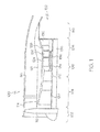
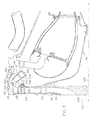
high pressure compressor 122 andannular combustor 124 is illustrated, In addition to thecompressor 122 andcombustor 124, FIG. 2 depicts adiffuser 204 and adeswirl assembly 206, each disposed about alongitudinal axis 207. Thehigh pressure compressor 122 is preferably a centrifugal compressor and includes animpeller 208 and ashroud 210 disposed in acompressor housing 211. Theimpeller 208, as alluded to above, is driven by thehigh pressure turbine 126 and rotates about thelongitudinal axis 207. Theshroud 210 is disposed around theimpeller 208 and defines an impellerdischarge flow passage 212 therewith that extends radially outwardly. - The
diffuser 204 is coupled to theshroud 210 and is configured to decrease the velocity and increase the static pressure of air that is received therefrom. In this regard, any one of numerousconventional diffusers 204 suitable for operating with a centrifugal compressor may be employed. In any case, thediffuser 204 includes aninlet 214, anoutlet 216, and aflow path 218 that each communicates with thepassage 212, and theflow path 218 is configured to direct the received air flow radially outwardly. - The
deswirl assembly 206 communicates with thediffuser 204 and is configured to substantially remove swirl from air received therefrom, to thereby decrease the Mach number of the air flow. Thedeswirl assembly 206 includes an innerannular wall 220, an outerannular wall 222, and two pluralities ofvanes walls flow path 228 that is configured to redirect the air from its radially outward direction to a radially inward and axially downstream direction. In this regard, thewalls flow path 228 extends between aninlet 230 andoutlet 232 in an are 233 so that when the air exits theoutlet 232, it is directed at an angle and toward thelongitudinal axis 207 and theannular combustor 124. As the angle of thearc 233 is increased the variation of the air angle between theinner wall 220 and outwall 222 is increased. - As briefly mentioned above, the two pluralities of
vanes walls vanes assembly 206, eachwall slots slots vanes slots vanes walls - To condition the airflow to a sufficiently low Mach number, each vane preferably has a substantially identical predetermined shape and is positioned in the
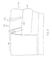
flow path 228 at a predetermined angle relative to thewaits Exemplary vanes 300, which are shown as being implemented into the two pluralities ofvanes vanes 300 from forward to aft, while FIG. 4 is the deswirl assembly shown in FIG. 3 looking at thevanes 300 from aft to forward. - Each
vane 300 includes aleading edge 302 and a trailingedge 304. Aconcave pressure surface 306 and aconvex suction surface 308 extend between the leading and trailingedges vanes 300 preferably each have a uniformly shaped curved axial cross-section from top 310 tobottom 312. In this regard, a number of thevanes 300 having substantially identical shapes may be mass produced from a single sheet of material. Specifically, the sheet of material may be suitably pressed into an appropriate curve shape to form the concave andconvex surfaces vanes 300 may be cut from the single sheet of material. - As mentioned previously, each
vane 300 of the two pluralities ofvanes walls vanes 300 are each placed such that theconcave pressure surface 306 faces outwardly toward the outerannular wall 222 and theconvex suction surface 308 faces inwardly toward the innerannular wall 220. Angling thevanes 300 in this preferred embodiment reduces the variation in air angle between the walls 220,222. In one exemplary embodiment, thevanes 300 are disposed such that an angle between theconcave pressure surface 208 the innerannular wall 220 is about 110.8°. However, it will be appreciated that the particular angle at which thevanes walls - The degree to which the
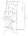
vanes vanes vanes 224 are equally spaced apart from one another and the trailing edge of each vane is disposed around a firstcircumferential position 242 around the innerannular wall 220, while the vanes of the second plurality ofvanes 226 are also equally spaced apart from one another but the leading edge of each is disposed around a secondcircumferential position 244. Although the first and secondcircumferential positions circumferential position 242 is disposed upstream of the secondcircumferential position 244, the firstcircumferential position 242 may alternatively be disposed downstream of the secondcircumferential position 244, or may overlap. - Additionally, the second plurality of
vanes 226 are preferably staggered between the first plurality ofvanes 224. For instance, as shown in FIG. 5 viewing thevanes 300 from forward 250 to aft 252, onevane 226b of the second plurality ofvanes 226 is preferably disposed between twovanes vanes 224 and biased toward thepressure surface 306 of vane 224b. in one exemplary embodiment, adistance 254 betweenvane 226b of the second plurality ofvanes 226 andvane 224b of the first plurality ofvanes 224 is about 35% of thedistance 256 betweenvanes vanes 224. It will be appreciated, however, that the particular distances between all of the vanes may largely depend on the angling thereof relative to thewalls - It will further be appreciated that although two pluralities of
vases vanes - An improved downcanted deswirl assembly has now been provided that includes a plurality of vanes that are configured to aerodynamically couple a centrifugal compressor and an axial through-flow combustor. Additionally, the deswirl assembly is relatively inexpensive and simple to manufacture and is capable of directing and conditioning the air flowing therethrough for optimal engine performance
- While the invention has been described with reference to a preferred embodiment, it will be understood by those skilled in the art that various changes may be made and equivalents may be substituted for elements thereof without departing from the scope of the invention. In addition, many modifications may be made to adapt to a particular situation or material to the teachings of the invention without departing from the essential scope thereof. Therefore, it is intended that the invention not be limited to the particular embodiment disclosed as the best mode contemplated for carrying out this invention, but that the invention will include all embodiments falling within the scope of the appended claims.
Claims (9)
- A deswirl assembly (206) for receiving air flow from a diffuser, the deswirl assembly (206) comprising:an annular housing including an inner annular wall (220), an outer annular wall (222) disposed concentric to the inner annular wall (220), and a flowpath (228) defined therebetween; anda plurality of vanes (224) disposed in the flowpath (228) in a substantially annular pattern, each vane (224) having a leading edge (302), a trailing edge (304), a convex surface (308), and concave surface (306), each of the convex and concave surfaces (308, 306) extending between the leading and trailing edges (302, 304), each vane (2240) extending between and angled relative to the inner and the outer annular walls (220, 222) such that the concave surface (306) faces the outer annular wall (222) and the convex surface (308) faces the inner annular wall (220).
- The deswirl assembly (206) of claim 1, wherein each vane (224) has an axial cross section shape, and each axial cross section shape is substantially the same.
- The deswirl assembly (206) of claim 1, further comprising a second plurality of vanes (226) disposed in the flowpath (228) in a substantially annular pattern downstream of the first plurality of vanes (224).
- The deswirl assembly (206) of claim 1, wherein the trailing edges (304) of the vanes of the first plurality of vanes (224) are disposed around a first circumferential position (242) around the inner annular wall (220) and the leading edges (302) of the vanes of the second plurality of vanes (226) are disposed around a second circumferential position (244) around the inner angular wall (220).
- The deswirl assembly (206) of claim 4, wherein the first and second circumferential positions (242, 244) do not overlap.
- The deswirl assembly (206) of claim 4, wherein the first circumferential position (242) is disposed downstream of the second circumferential position (244).
- The deswirl assembly (206) of claim 4, wherein the vanes of the second plurality of vanes (226) are each staggered between vanes of the first plurality of vanes (224).
- The deswirl assembly (206) of claim 7, wherein at least one vane (226b) of the second plurality of vanes (226) is disposed between two vanes (224a, 224b) of the first plurality of vanes (224) and a first distance (254) between the at least one vane (226b) of the second plurality of vanes and one (224b) of the two vanes (224a, 224b) of the first plurality of vanes (224) is less than a second distance (256) between the two vanes (224a, 224b) of the first plurality of vanes (224).
- The deswirl assembly of claim 8, wherein the first distance (254) is about 35% of the second distance (256).
Applications Claiming Priority (1)
| Application Number | Priority Date | Filing Date | Title |
|---|---|---|---|
| US11/350,537 US20070183890A1 (en) | 2006-02-09 | 2006-02-09 | Leaned deswirl vanes behind a centrifugal compressor in a gas turbine engine |
Publications (2)
| Publication Number | Publication Date |
|---|---|
| EP1818511A2 true EP1818511A2 (en) | 2007-08-15 |
| EP1818511A3 EP1818511A3 (en) | 2007-12-05 |
Family
ID=38024292
Family Applications (1)
| Application Number | Title | Priority Date | Filing Date |
|---|---|---|---|
| EP07101951A Withdrawn EP1818511A3 (en) | 2006-02-09 | 2007-02-08 | Leaned deswirl vanes behind a centrifugal compressor in a gas turbine engine |
Country Status (3)
| Country | Link |
|---|---|
| US (1) | US20070183890A1 (en) |
| EP (1) | EP1818511A3 (en) |
| CA (1) | CA2577461A1 (en) |
Cited By (7)
| Publication number | Priority date | Publication date | Assignee | Title |
|---|---|---|---|---|
| FR2922939A1 (en) * | 2007-10-26 | 2009-05-01 | Snecma Sa | Turbomachine e.g. jet engine, for aircraft, has diffuser with upstream part having portion inclined with respect to direction perpendicular to axis, towards front of turbomachine, in plane, such that diffuser has gooseneck form |
| FR2927949A1 (en) * | 2008-02-27 | 2009-08-28 | Snecma Sa | TURBOMACHINE DIFFUSER COMPRISING SCREWED ANNULAR SAILS |
| EP2123863A1 (en) * | 2008-05-23 | 2009-11-25 | Honeywell International Inc. | Pre-diffuser for centrifugal compressor |
| FR2955364A1 (en) * | 2010-01-19 | 2011-07-22 | Snecma | DIFFUSER-RECTIFIER CONNECTION FOR A CENTRIFUGAL COMPRESSOR |
| EP2128388A3 (en) * | 2008-05-30 | 2012-06-27 | Honeywell International Inc. | Diffuser |
| CN107725479A (en) * | 2017-09-26 | 2018-02-23 | 中国科学院工程热物理研究所 | A kind of rotor casing structure inside inside rotating disc cavities and the engine comprising the structure |
| RU2667736C2 (en) * | 2014-09-02 | 2018-09-24 | Ман Дизель Унд Турбо Се | Stage of centrifugal compressor (options) |
Families Citing this family (13)
| Publication number | Priority date | Publication date | Assignee | Title |
|---|---|---|---|---|
| FR2920032B1 (en) * | 2007-08-13 | 2014-08-22 | Snecma | DIFFUSER OF A TURBOMACHINE |
| US7984614B2 (en) * | 2008-11-17 | 2011-07-26 | Honeywell International Inc. | Plasma flow controlled diffuser system |
| FR2941742B1 (en) * | 2009-02-05 | 2011-08-19 | Snecma | DIFFUSER-RECTIFIER ASSEMBLY FOR A TURBOMACHINE |
| DE102015219556A1 (en) | 2015-10-08 | 2017-04-13 | Rolls-Royce Deutschland Ltd & Co Kg | Diffuser for radial compressor, centrifugal compressor and turbo machine with centrifugal compressor |
| US10208628B2 (en) | 2016-03-30 | 2019-02-19 | Honeywell International Inc. | Turbine engine designs for improved fine particle separation efficiency |
| US20180135516A1 (en) * | 2016-11-16 | 2018-05-17 | Honeywell International Inc. | Scavenge methodologies for turbine engine particle separation concepts |
| US10718222B2 (en) | 2017-03-27 | 2020-07-21 | General Electric Company | Diffuser-deswirler for a gas turbine engine |
| US10816014B2 (en) * | 2018-07-25 | 2020-10-27 | Honeywell International Inc. | Systems and methods for turbine engine particle separation |
| US11098730B2 (en) | 2019-04-12 | 2021-08-24 | Rolls-Royce Corporation | Deswirler assembly for a centrifugal compressor |
| US11441516B2 (en) | 2020-07-14 | 2022-09-13 | Rolls-Royce North American Technologies Inc. | Centrifugal compressor assembly for a gas turbine engine with deswirler having sealing features |
| US11286952B2 (en) | 2020-07-14 | 2022-03-29 | Rolls-Royce Corporation | Diffusion system configured for use with centrifugal compressor |
| US11578654B2 (en) | 2020-07-29 | 2023-02-14 | Rolls-Royce North American Technologies Inc. | Centrifical compressor assembly for a gas turbine engine |
| US11619172B1 (en) | 2022-03-01 | 2023-04-04 | General Electric Company | Detonation combustion systems |
Citations (7)
| Publication number | Priority date | Publication date | Assignee | Title |
|---|---|---|---|---|
| CH289476A (en) * | 1950-03-03 | 1953-03-15 | Rolls Royce | Axial flow line of annular cross section with guide device. |
| GB712523A (en) * | 1950-03-03 | 1954-07-28 | Rolls Royce | Improvements in or relating to guide vane assemblies in annular fluid ducts |
| US2962260A (en) * | 1954-12-13 | 1960-11-29 | United Aircraft Corp | Sweep back in blading |
| GB1256122A (en) * | 1968-03-06 | 1971-12-08 | Gen Electric | Improvements in axial flow compressors and turbofan engines employing same |
| DE19502808A1 (en) * | 1995-01-30 | 1996-08-08 | Man B & W Diesel Ag | Radial-flow compressor with deflected flow duct |
| WO2001018404A1 (en) * | 1999-09-07 | 2001-03-15 | General Electric Company | Deswirler system for centrifugal compressor |
| US20050186070A1 (en) * | 2004-02-23 | 2005-08-25 | Ling-Zhong Zeng | Fan assembly and method |
Family Cites Families (14)
| Publication number | Priority date | Publication date | Assignee | Title |
|---|---|---|---|---|
| US2414551A (en) * | 1941-07-21 | 1947-01-21 | Northrop Aircraft Inc | Compressor |
| US2419669A (en) * | 1942-05-08 | 1947-04-29 | Fed Reserve Bank | Diffuser for centrifugal compressors |
| US3285005A (en) * | 1964-05-28 | 1966-11-15 | Continental Aviat & Eng Corp | Turbine engine construction |
| US4027997A (en) * | 1975-12-10 | 1977-06-07 | General Electric Company | Diffuser for a centrifugal compressor |
| US4455121A (en) * | 1982-11-01 | 1984-06-19 | Avco Corporation | Rotating turbine stator |
| DE3882463T2 (en) * | 1987-09-01 | 1993-11-11 | Hitachi Ltd | Diffuser for centrifugal compressors. |
| US4824325A (en) * | 1988-02-08 | 1989-04-25 | Dresser-Rand Company | Diffuser having split tandem low solidity vanes |
| JP3356510B2 (en) * | 1992-12-25 | 2002-12-16 | 株式会社荏原製作所 | Centrifugal or mixed flow pump vaned diffuser |
| JP3110205B2 (en) * | 1993-04-28 | 2000-11-20 | 株式会社日立製作所 | Centrifugal compressor and diffuser with blades |
| US5555721A (en) * | 1994-09-28 | 1996-09-17 | General Electric Company | Gas turbine engine cooling supply circuit |
| JP3686300B2 (en) * | 2000-02-03 | 2005-08-24 | 三菱重工業株式会社 | Centrifugal compressor |
| US6540481B2 (en) * | 2001-04-04 | 2003-04-01 | General Electric Company | Diffuser for a centrifugal compressor |
| US7025566B2 (en) * | 2003-11-04 | 2006-04-11 | Pratt & Whitney Canada Corp. | Hybrid vane island diffuser |
| US7500364B2 (en) * | 2005-11-22 | 2009-03-10 | Honeywell International Inc. | System for coupling flow from a centrifugal compressor to an axial combustor for gas turbines |
-
2006
- 2006-02-09 US US11/350,537 patent/US20070183890A1/en not_active Abandoned
-
2007
- 2007-02-07 CA CA002577461A patent/CA2577461A1/en not_active Abandoned
- 2007-02-08 EP EP07101951A patent/EP1818511A3/en not_active Withdrawn
Patent Citations (7)
| Publication number | Priority date | Publication date | Assignee | Title |
|---|---|---|---|---|
| CH289476A (en) * | 1950-03-03 | 1953-03-15 | Rolls Royce | Axial flow line of annular cross section with guide device. |
| GB712523A (en) * | 1950-03-03 | 1954-07-28 | Rolls Royce | Improvements in or relating to guide vane assemblies in annular fluid ducts |
| US2962260A (en) * | 1954-12-13 | 1960-11-29 | United Aircraft Corp | Sweep back in blading |
| GB1256122A (en) * | 1968-03-06 | 1971-12-08 | Gen Electric | Improvements in axial flow compressors and turbofan engines employing same |
| DE19502808A1 (en) * | 1995-01-30 | 1996-08-08 | Man B & W Diesel Ag | Radial-flow compressor with deflected flow duct |
| WO2001018404A1 (en) * | 1999-09-07 | 2001-03-15 | General Electric Company | Deswirler system for centrifugal compressor |
| US20050186070A1 (en) * | 2004-02-23 | 2005-08-25 | Ling-Zhong Zeng | Fan assembly and method |
Cited By (19)
| Publication number | Priority date | Publication date | Assignee | Title |
|---|---|---|---|---|
| FR2922939A1 (en) * | 2007-10-26 | 2009-05-01 | Snecma Sa | Turbomachine e.g. jet engine, for aircraft, has diffuser with upstream part having portion inclined with respect to direction perpendicular to axis, towards front of turbomachine, in plane, such that diffuser has gooseneck form |
| US8875517B2 (en) | 2008-02-27 | 2014-11-04 | Snecma | Diffuser for turbine engine including indented annular webs |
| RU2488718C2 (en) * | 2008-02-27 | 2013-07-27 | Снекма | Gas turbine engine diffuser and gas turbine engine with such diffuser |
| CN101960151B (en) * | 2008-02-27 | 2012-10-24 | 斯奈克玛 | Diffuser for turbine engine including indented annular webs |
| WO2009115690A1 (en) * | 2008-02-27 | 2009-09-24 | Snecma | Diffuser for turbine engine including indented annular webs |
| FR2927949A1 (en) * | 2008-02-27 | 2009-08-28 | Snecma Sa | TURBOMACHINE DIFFUSER COMPRISING SCREWED ANNULAR SAILS |
| JP2011513624A (en) * | 2008-02-27 | 2011-04-28 | スネクマ | Turbine engine diffuser with a notched annular web |
| EP2123863A1 (en) * | 2008-05-23 | 2009-11-25 | Honeywell International Inc. | Pre-diffuser for centrifugal compressor |
| US8438854B2 (en) | 2008-05-23 | 2013-05-14 | Honeywell International Inc. | Pre-diffuser for centrifugal compressor |
| EP2128388A3 (en) * | 2008-05-30 | 2012-06-27 | Honeywell International Inc. | Diffuser |
| WO2011089355A1 (en) * | 2010-01-19 | 2011-07-28 | Snecma | Diffuser-rectifier connection for a centrifugal compressor |
| CN102713308A (en) * | 2010-01-19 | 2012-10-03 | 斯奈克玛 | Diffuser-rectifier connection for a centrifugal compressor |
| RU2561790C2 (en) * | 2010-01-19 | 2015-09-10 | Снекма | Connection diffuser-straightening device for centrifugal compressor |
| US9291171B2 (en) | 2010-01-19 | 2016-03-22 | Snecma | Diffuser-guide vane connection for a centrifugal compressor |
| CN102713308B (en) * | 2010-01-19 | 2017-07-18 | 斯奈克玛 | The diffuser guide vane attachment means of centrifugal compressor |
| FR2955364A1 (en) * | 2010-01-19 | 2011-07-22 | Snecma | DIFFUSER-RECTIFIER CONNECTION FOR A CENTRIFUGAL COMPRESSOR |
| RU2667736C2 (en) * | 2014-09-02 | 2018-09-24 | Ман Дизель Унд Турбо Се | Stage of centrifugal compressor (options) |
| CN107725479B (en) * | 2017-09-26 | 2019-09-24 | 中国科学院工程热物理研究所 | A kind of rotor casing structure inside inside rotating disc cavities and the engine comprising the structure |
| CN107725479A (en) * | 2017-09-26 | 2018-02-23 | 中国科学院工程热物理研究所 | A kind of rotor casing structure inside inside rotating disc cavities and the engine comprising the structure |
Also Published As
| Publication number | Publication date |
|---|---|
| CA2577461A1 (en) | 2007-08-09 |
| EP1818511A3 (en) | 2007-12-05 |
| US20070183890A1 (en) | 2007-08-09 |
Similar Documents
| Publication | Publication Date | Title |
|---|---|---|
| EP1818511A2 (en) | Leaned deswirl vanes behind a centrifugal compressor in a gas turbine engine | |
| US7500364B2 (en) | System for coupling flow from a centrifugal compressor to an axial combustor for gas turbines | |
| US8438854B2 (en) | Pre-diffuser for centrifugal compressor | |
| US7189059B2 (en) | Compressor including an enhanced vaned shroud | |
| EP2778427B1 (en) | Compressor bleed self-recirculating system | |
| US8157514B2 (en) | Components for gas turbine engines | |
| EP2204533B1 (en) | Methods, systems and/or apparatus relating to inducers for turbine engines | |
| EP2775119B1 (en) | Compressor shroud reverse bleed holes | |
| CN105793577B (en) | Curved diffuser passage section for centrifugal compressor | |
| CN107084004B (en) | Impingement hole for a turbine engine component | |
| EP3791047B1 (en) | Outlet guide vane | |
| US20070147987A1 (en) | Self-aspirated flow control system for centrifugal compressors | |
| EP3832144B1 (en) | Diffuser pipe with radially-outward exit | |
| CA3081250A1 (en) | Diffuser pipe with exit flare | |
| EP3599344A1 (en) | Systems for turbine engine particle separation | |
| CN109083687B (en) | Method of minimizing cross flow across cooling holes and component for turbine engine | |
| EP2126367B1 (en) | Turbogas system multistage compressor | |
| WO2007023449A2 (en) | Engine |
Legal Events
| Date | Code | Title | Description |
|---|---|---|---|
| PUAI | Public reference made under article 153(3) epc to a published international application that has entered the european phase |
Free format text: ORIGINAL CODE: 0009012 |
|
| AK | Designated contracting states |
Kind code of ref document: A2 Designated state(s): AT BE BG CH CY CZ DE DK EE ES FI FR GB GR HU IE IS IT LI LT LU LV MC NL PL PT RO SE SI SK TR |
|
| AX | Request for extension of the european patent |
Extension state: AL BA HR MK YU |
|
| PUAL | Search report despatched |
Free format text: ORIGINAL CODE: 0009013 |
|
| AK | Designated contracting states |
Kind code of ref document: A3 Designated state(s): AT BE BG CH CY CZ DE DK EE ES FI FR GB GR HU IE IS IT LI LT LU LV MC NL PL PT RO SE SI SK TR |
|
| AX | Request for extension of the european patent |
Extension state: AL BA HR MK YU |
|
| 17P | Request for examination filed |
Effective date: 20080325 |
|
| 17Q | First examination report despatched |
Effective date: 20080609 |
|
| AKX | Designation fees paid |
Designated state(s): FR |
|
| REG | Reference to a national code |
Ref country code: DE Ref legal event code: 8566 |
|
| GRAP | Despatch of communication of intention to grant a patent |
Free format text: ORIGINAL CODE: EPIDOSNIGR1 |
|
| STAA | Information on the status of an ep patent application or granted ep patent |
Free format text: STATUS: THE APPLICATION IS DEEMED TO BE WITHDRAWN |
|
| 18D | Application deemed to be withdrawn |
Effective date: 20100408 |