EP1818224A1 - Hinge mechanism for motor vehicle bonnet - Google Patents
Hinge mechanism for motor vehicle bonnet Download PDFInfo
- Publication number
- EP1818224A1 EP1818224A1 EP06270094A EP06270094A EP1818224A1 EP 1818224 A1 EP1818224 A1 EP 1818224A1 EP 06270094 A EP06270094 A EP 06270094A EP 06270094 A EP06270094 A EP 06270094A EP 1818224 A1 EP1818224 A1 EP 1818224A1
- Authority
- EP
- European Patent Office
- Prior art keywords
- hinge
- bonnet
- slot
- stud
- deployed position
- Prior art date
- Legal status (The legal status is an assumption and is not a legal conclusion. Google has not performed a legal analysis and makes no representation as to the accuracy of the status listed.)
- Granted
Links
- 230000007246 mechanism Effects 0.000 title claims abstract description 29
- 238000013459 approach Methods 0.000 claims description 9
- 229910000831 Steel Inorganic materials 0.000 claims description 4
- 239000010959 steel Substances 0.000 claims description 4
- 210000000988 bone and bone Anatomy 0.000 claims description 2
- 239000013536 elastomeric material Substances 0.000 claims description 2
- 238000012986 modification Methods 0.000 description 4
- 230000004048 modification Effects 0.000 description 4
- 230000000694 effects Effects 0.000 description 2
- 239000002184 metal Substances 0.000 description 1
- 230000010355 oscillation Effects 0.000 description 1
- 229920003023 plastic Polymers 0.000 description 1
- 239000004033 plastic Substances 0.000 description 1
- 239000012858 resilient material Substances 0.000 description 1
- 230000000630 rising effect Effects 0.000 description 1
Images

Classifications
-
- B—PERFORMING OPERATIONS; TRANSPORTING
- B60—VEHICLES IN GENERAL
- B60R—VEHICLES, VEHICLE FITTINGS, OR VEHICLE PARTS, NOT OTHERWISE PROVIDED FOR
- B60R21/00—Arrangements or fittings on vehicles for protecting or preventing injuries to occupants or pedestrians in case of accidents or other traffic risks
- B60R21/34—Protecting non-occupants of a vehicle, e.g. pedestrians
-
- E—FIXED CONSTRUCTIONS
- E05—LOCKS; KEYS; WINDOW OR DOOR FITTINGS; SAFES
- E05D—HINGES OR SUSPENSION DEVICES FOR DOORS, WINDOWS OR WINGS
- E05D11/00—Additional features or accessories of hinges
-
- B—PERFORMING OPERATIONS; TRANSPORTING
- B60—VEHICLES IN GENERAL
- B60R—VEHICLES, VEHICLE FITTINGS, OR VEHICLE PARTS, NOT OTHERWISE PROVIDED FOR
- B60R21/00—Arrangements or fittings on vehicles for protecting or preventing injuries to occupants or pedestrians in case of accidents or other traffic risks
- B60R21/34—Protecting non-occupants of a vehicle, e.g. pedestrians
- B60R21/38—Protecting non-occupants of a vehicle, e.g. pedestrians using means for lifting bonnets
-
- B—PERFORMING OPERATIONS; TRANSPORTING
- B62—LAND VEHICLES FOR TRAVELLING OTHERWISE THAN ON RAILS
- B62D—MOTOR VEHICLES; TRAILERS
- B62D25/00—Superstructure or monocoque structure sub-units; Parts or details thereof not otherwise provided for
- B62D25/08—Front or rear portions
- B62D25/10—Bonnets or lids, e.g. for trucks, tractors, busses, work vehicles
- B62D25/12—Parts or details thereof
-
- B—PERFORMING OPERATIONS; TRANSPORTING
- B60—VEHICLES IN GENERAL
- B60R—VEHICLES, VEHICLE FITTINGS, OR VEHICLE PARTS, NOT OTHERWISE PROVIDED FOR
- B60R21/00—Arrangements or fittings on vehicles for protecting or preventing injuries to occupants or pedestrians in case of accidents or other traffic risks
- B60R21/34—Protecting non-occupants of a vehicle, e.g. pedestrians
- B60R2021/343—Protecting non-occupants of a vehicle, e.g. pedestrians using deformable body panel, bodywork or components
-
- E—FIXED CONSTRUCTIONS
- E05—LOCKS; KEYS; WINDOW OR DOOR FITTINGS; SAFES
- E05Y—INDEXING SCHEME ASSOCIATED WITH SUBCLASSES E05D AND E05F, RELATING TO CONSTRUCTION ELEMENTS, ELECTRIC CONTROL, POWER SUPPLY, POWER SIGNAL OR TRANSMISSION, USER INTERFACES, MOUNTING OR COUPLING, DETAILS, ACCESSORIES, AUXILIARY OPERATIONS NOT OTHERWISE PROVIDED FOR, APPLICATION THEREOF
- E05Y2900/00—Application of doors, windows, wings or fittings thereof
- E05Y2900/50—Application of doors, windows, wings or fittings thereof for vehicles
- E05Y2900/53—Type of wing
- E05Y2900/536—Hoods
Definitions
- the present invention relates to a hinge mechanism to lift the rear edge of a hood or a bonnet of a motor vehicle providing improved pedestrian safety.
- hinge mechanisms have been proposed to mount the bonnet to a body structure such that, in the event of a detected collision with a pedestrian, the rear edge of the bonnet is raised by means of at least one lift actuator from its normal closed position to a partially raised position.
- Such hinge mechanisms usually have a first operating mode in which the front edge of the bonnet can be lifted in a normal way about a pivot axis defined at the rear of the bonnet by the hinge and a second operating mode in which the rear edge of the bonnet can be raised by the lift actuator.
- One known type of hinge mechanism allows for upward movement of the bonnet by means of a co-operating stud and slot arranged on the hinge.
- Each hinge mechanism has a slot which releasably connects with a stud attached to the body structure so that the stud can move freely along the slot under the application of the upward force applied by the lift actuators until it strikes the end of the slot.
- a hinge mechanism for providing a hinged connection between a bonnet and a body structure of a motor vehicle, the hinge mechanism allowing the rear edge of the bonnet to be lifted from a normal position to a deployed position under an upward force, the hinge mechanism including first and second hinge members which in normal position are fast with each other but which move relative to each other when the bonnet is moved from the normal position to the deployed position, the first hinge member having a slot and the second hinge member having a stud which is slidable in the slot during movement of the bonnet from the normal position into the deployed position and wherein energy dissipating means is provided to dissipate impact energy of the stud against the end of the slot as the bonnet approaches the deployed position.
- the energy dissipating means may be a resiliently deformable element connected to the first hinge member at one end of the slot.
- the energy dissipating means includes at least one bridge piece formed between an aperture in the first hinge member and one end of the slot such that the or each bridge piece can deform under impact energy of the stud against the end of the slot as the bonnet approaches the deployed position.
- the energy dissipating means is a plate including at least one bridge piece formed between two apertures, the plate being attached to first hinge member in such a way that the stud is slidable along one of the two apertures and that the or each bridge piece can be deform under impact energy of the stud as the bonnet approaches the deployed position.
- a motor vehicle having at least one hinge mechanism according to the first aspect of the invention.
- a hinge mechanism 10 intended to pivotally connect a rear edge of a bonnet 11 to a vehicle body structure (not shown). It will be noted that the bonnet 11 is pivotally attached to the body structure in a conventional manner by two hinge mechanisms 10 (only one shown) each located towards respective right and left hand sides of the bonnet 11.
- Each hinge mechanism 10 is associated with a lift actuator (not shown).
- Each hinge mechanism 10 comprises, in this example, three steel leaves or hinge members, a lower leaf or hinge member 12 attached to part of the body structure, an upper leaf or hinge member 13 attached to the bonnet 11 and a middle leaf or hinge member 14 connected to the lower and upper leaves 12, 13.
- the lower leaf 12 has, at its rearward end, an upwardly extending portion 15 which is pivotally attached at a pivot axis 9 to the rearward end of the middle leaf 14. At its free end the middle leaf 14 has a laterally extending stud 16.
- the upper leaf 13 has at its forward end an elongate slot 17. As can best be seen in Figs 2 and 3, the stud 16 extends through the slot 17 and is slideable along the slot 17.
- a guide link 18 is pivotally connected in a known manner at one 19 of its ends to the middle leaf 14 and at its other end 20 to the upper leaf 13.
- the end of the upper leaf 13 remote from the slot 17 is releasably attached to the middle leaf 14 by a releasable locking member.
- the locking member is a moveable pin (not shown) which engages apertures 21, 22 formed in the upper and middles leaves 13, 14.
- other locking members are possible such as a shear pin or a releasable locking member which is formed by the co-operation of a tab in the upper leaf, with a corresponding recess in the middle leaf.
- the upper leaf 13 is provided with an energy dissipating means at the rearward end of the slot 17.
- the energy dissipating means shown in Fig.4 is a resiliently deformable element 30 made of elastomeric material.
- the deformable element 30 is, in this example, moulded onto the upper leaf 13 such that part of the rearward end of the slot 17 is closed, thus forming a buffer wall 31.
- the bonnet 11 is articulated around the pivot axis 9 between the lower leaf 12 and the middle leaf 14, the upper leaf 13 being prevented from pivoting with respect to the middle leaf 14 about the stud 16 by the releasable locking member.
- the locking member When a pedestrian collision is detected, the locking member is removed from the apertures 21,22 and the lift actuator begins to deploy.
- the upward force exerted by the lift actuators lifts the rear end of the bonnet 11 into a deployed position and opens the hinge mechanism 10 into an extended position (Fig.3) in which the stud 16 of the middle leaf 14 slides along the slot 17 of the upper leaf 13 until the stud 16 strikes the buffer wall 31 of the deformable element 30 as the bonnet approaches the deployed position.
- the hysteresis of the deformable element 30 absorbs a large proportion of the kinetic energy of the rising bonnet 10 thus limiting any tendency for the bonnet 10 to oscillate after the lift actuator has been fully deployed.
- the resiliently deformable element 30 has numerous elongated cavities 40, each cavity having a bone shaped form with a longitudinal axis which is substantially perpendicular to the direction of travel of the stud 16 along the slot 17. It has been found that with such a shape the deformable element 30 is able to dissipate a large amount of energy.
- the element 30 may have any number of cavities 40 and any type of shape according to the amount of energy that it is necessary to dissipate.
- the rearward end of the slot 17 is formed by an end wall 50 behind which is formed an aperture 51 so that a bridge piece formed between the aperture 51 and the end wall 50 can deform under the striking force of the stud 16 against this wall 51, thereby dissipating energy from the over-travel of stud 16.
- several apertures can be successively formed on the upper leaf behind the slot 17, thus forming several bridge pieces which can deform progressively.
- Fig. 7 shows a further alternative embodiment of the energy dissipating means which is in the form of a steel plate 70 having two apertures 71 and 72 between which is formed a bridge piece 73.
- the plate 70 is attached to the upper leaf 13 by means of rivets in such a way that the stud 16 extends through the slot 17 and the aperture 71 of the plate 70 and is slidable along the slot 17 and the aperture 71.
- the stud 16 slides along the slot 17 and the aperture 71 until the stud 16 strikes the bridge piece 73 of the plate 70 as the bonnet approaches the deployed position. Under the striking force of the stud 16 the bridge piece 73 is deformed thereby dissipating energy from the over-travel of the stud 16.
- the plate 70 can have several bridge pieces 73 which can deform progressively.
- the energy dissipating means can be applied to other hinge mechanisms in which a stud and slot connection is used to limit the deploying movement of the bonnet from the normal, closed position to a deployed position in the event of a pedestrian collision, for instance as described in GB 2 410 924 which discloses only two leaves where the slot is formed on the lower leaf connected to the body structure.
- the buffer wall 31 can have a surface that curves outward instead of being perpendicular.
- the plate 70 can be made of metal other than steel or can even be made of a resilient material such as plastics.
- the plate can also have a tongue which extends through the slot and acts as an energy dissipating means.
Landscapes
- Engineering & Computer Science (AREA)
- Mechanical Engineering (AREA)
- Chemical & Material Sciences (AREA)
- Combustion & Propulsion (AREA)
- Transportation (AREA)
- Superstructure Of Vehicle (AREA)
Abstract
Description
- The present invention relates to a hinge mechanism to lift the rear edge of a hood or a bonnet of a motor vehicle providing improved pedestrian safety.
- Various hinge mechanisms have been proposed to mount the bonnet to a body structure such that, in the event of a detected collision with a pedestrian, the rear edge of the bonnet is raised by means of at least one lift actuator from its normal closed position to a partially raised position. Such hinge mechanisms usually have a first operating mode in which the front edge of the bonnet can be lifted in a normal way about a pivot axis defined at the rear of the bonnet by the hinge and a second operating mode in which the rear edge of the bonnet can be raised by the lift actuator. One known type of hinge mechanism allows for upward movement of the bonnet by means of a co-operating stud and slot arranged on the hinge. See, for example,
GB 2 410 924 - It is a problem with such a known hinge mechanism that when the bonnet is lifted by the lift actuators, the magnitude of the impact of the stud with the end of the slot causes the bonnet to oscillate or flutter. This oscillation of the bonnet can have a negative effect on the impact performance of the bonnet, especially if the bonnet is flexing upwards when a pedestrian strikes the bonnet. Then the relative velocity is greater than if the bonnet is stationary (relative to the vehicle) or is moving downward. To overcome this problem, it is proposed in
GB 2 410 924 - It is an object of this invention to provide an improved hinge mechanism for a motor vehicle bonnet which solves or alleviates the problem associated with the prior art.
- According to a first aspect of the invention there is provided a hinge mechanism for providing a hinged connection between a bonnet and a body structure of a motor vehicle, the hinge mechanism allowing the rear edge of the bonnet to be lifted from a normal position to a deployed position under an upward force, the hinge mechanism including first and second hinge members which in normal position are fast with each other but which move relative to each other when the bonnet is moved from the normal position to the deployed position, the first hinge member having a slot and the second hinge member having a stud which is slidable in the slot during movement of the bonnet from the normal position into the deployed position and wherein energy dissipating means is provided to dissipate impact energy of the stud against the end of the slot as the bonnet approaches the deployed position.
- The energy dissipating means may be a resiliently deformable element connected to the first hinge member at one end of the slot.
- In an alternative, the energy dissipating means includes at least one bridge piece formed between an aperture in the first hinge member and one end of the slot such that the or each bridge piece can deform under impact energy of the stud against the end of the slot as the bonnet approaches the deployed position.
- In another alternative, the energy dissipating means is a plate including at least one bridge piece formed between two apertures, the plate being attached to first hinge member in such a way that the stud is slidable along one of the two apertures and that the or each bridge piece can be deform under impact energy of the stud as the bonnet approaches the deployed position.
- According to a second aspect of the invention there is provided a motor vehicle having at least one hinge mechanism according to the first aspect of the invention.
- The invention will now be described by way of example with reference to the accompanying drawings of which: -
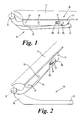
- Fig.1 is a schematic of a hinge mechanism connected to the rear edge of a bonnet in its normal position,
- Fig.2 is a view similar to Fig.1 but showing the hinge mechanism in its open position, i.e. when the bonnet is opened in the normal way,
- Fig.3 is a view similar to Fig.1 but showing the hinge mechanism in an extended position in the event of a detected collision with a pedestrian,
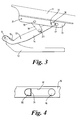
- Fig.4 is a scrap view in to the direction of arrow B in Fig.1 to a larger scale,
- Figs. 5 and 6 are views similar to Fig.4 but showing two alternatives respectively, and
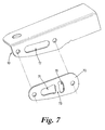
- Fig. 7 is an exploded view to a larger scale according to a second embodiment of the present invention.
- With reference to Figs.1 to 3, there is shown a
hinge mechanism 10 intended to pivotally connect a rear edge of abonnet 11 to a vehicle body structure (not shown). It will be noted that thebonnet 11 is pivotally attached to the body structure in a conventional manner by two hinge mechanisms 10 (only one shown) each located towards respective right and left hand sides of thebonnet 11. - Each
hinge mechanism 10 is associated with a lift actuator (not shown). Eachhinge mechanism 10 comprises, in this example, three steel leaves or hinge members, a lower leaf or hingemember 12 attached to part of the body structure, an upper leaf or hingemember 13 attached to thebonnet 11 and a middle leaf or hingemember 14 connected to the lower andupper leaves - The
lower leaf 12 has, at its rearward end, an upwardly extendingportion 15 which is pivotally attached at apivot axis 9 to the rearward end of themiddle leaf 14. At its free end themiddle leaf 14 has a laterally extendingstud 16. - The
upper leaf 13 has at its forward end anelongate slot 17. As can best be seen in Figs 2 and 3, thestud 16 extends through theslot 17 and is slideable along theslot 17. - A
guide link 18 is pivotally connected in a known manner at one 19 of its ends to themiddle leaf 14 and at itsother end 20 to theupper leaf 13. - The end of the
upper leaf 13 remote from theslot 17 is releasably attached to themiddle leaf 14 by a releasable locking member. In this example, the locking member is a moveable pin (not shown) which engagesapertures - Referring now in particular to Fig. 4, the
upper leaf 13 is provided with an energy dissipating means at the rearward end of theslot 17. The energy dissipating means shown in Fig.4 is a resilientlydeformable element 30 made of elastomeric material. Thedeformable element 30 is, in this example, moulded onto theupper leaf 13 such that part of the rearward end of theslot 17 is closed, thus forming abuffer wall 31. - During normal operation of the
hinge mechanism 10, thebonnet 11 is articulated around thepivot axis 9 between thelower leaf 12 and themiddle leaf 14, theupper leaf 13 being prevented from pivoting with respect to themiddle leaf 14 about thestud 16 by the releasable locking member. - When a pedestrian collision is detected, the locking member is removed from the
apertures bonnet 11 into a deployed position and opens thehinge mechanism 10 into an extended position (Fig.3) in which thestud 16 of themiddle leaf 14 slides along theslot 17 of theupper leaf 13 until thestud 16 strikes thebuffer wall 31 of thedeformable element 30 as the bonnet approaches the deployed position. The hysteresis of thedeformable element 30 absorbs a large proportion of the kinetic energy of the risingbonnet 10 thus limiting any tendency for thebonnet 10 to oscillate after the lift actuator has been fully deployed. - In a modification shown in Fig. 5, the resiliently
deformable element 30 has numerouselongated cavities 40, each cavity having a bone shaped form with a longitudinal axis which is substantially perpendicular to the direction of travel of thestud 16 along theslot 17. It has been found that with such a shape thedeformable element 30 is able to dissipate a large amount of energy. Theelement 30 may have any number ofcavities 40 and any type of shape according to the amount of energy that it is necessary to dissipate. - In an alternative embodiment of the energy dissipating means shown in Fig. 6, the rearward end of the
slot 17 is formed by anend wall 50 behind which is formed anaperture 51 so that a bridge piece formed between theaperture 51 and theend wall 50 can deform under the striking force of thestud 16 against thiswall 51, thereby dissipating energy from the over-travel ofstud 16. In a modification several apertures can be successively formed on the upper leaf behind theslot 17, thus forming several bridge pieces which can deform progressively. - Fig. 7 shows a further alternative embodiment of the energy dissipating means which is in the form of a
steel plate 70 having twoapertures bridge piece 73. Theplate 70 is attached to theupper leaf 13 by means of rivets in such a way that thestud 16 extends through theslot 17 and theaperture 71 of theplate 70 and is slidable along theslot 17 and theaperture 71. Hence when a pedestrian collision is detected, thestud 16 slides along theslot 17 and theaperture 71 until thestud 16 strikes thebridge piece 73 of theplate 70 as the bonnet approaches the deployed position. Under the striking force of thestud 16 thebridge piece 73 is deformed thereby dissipating energy from the over-travel of thestud 16. In a modification theplate 70 can haveseveral bridge pieces 73 which can deform progressively. - Although the invention has been described by way of example with reference to a specific hinge mechanism, the energy dissipating means can be applied to other hinge mechanisms in which a stud and slot connection is used to limit the deploying movement of the bonnet from the normal, closed position to a deployed position in the event of a pedestrian collision, for instance as described in
GB 2 410 924 buffer wall 31 can have a surface that curves outward instead of being perpendicular. Theplate 70 can be made of metal other than steel or can even be made of a resilient material such as plastics. The plate can also have a tongue which extends through the slot and acts as an energy dissipating means.
Claims (12)
- A hinge mechanism (10) for providing a hinged connection between a bonnet (11) and a body structure of a motor vehicle, the hinge mechanism (10) allowing the rear edge of the bonnet (11) to be lifted from a normal position to a deployed position under an upward force, the hinge mechanism (10) including first (13) and second (14) hinge members which in normal position are fast with each other but which move relative to each other when the bonnet (11) is moved from the normal position to the deployed position, the first hinge member (13) having a slot (17) and the second hinge member (14) having a stud (16) which is slidable in the slot (17) during movement of the bonnet (11) from the normal position into the deployed position and wherein energy dissipating means (30; 50, 51) is provided to dissipate impact energy of the stud (16) against the end of the slot (17) as the bonnet (11) approaches the deployed position.
- A hinge as claimed in claim 1 in which the energy dissipating means is a resiliently deformable element (30) connected to the first hinge member (13) at one end of the slot (17).
- A hinge as claimed in claim 2 in which the deformable element (30) has at least one cavity (40).
- A hinge as claimed in claim 3 in which the or each cavity (40) is elongate and has a longitudinal axis which is substantially perpendicular to the travel direction of the stud (16).
- A hinge as claimed in claim 4 in which the or each cavity (40) is bone shaped.
- A hinge as claimed in any one of claim 2 to 5 in which the element (30) has a buffer wall (31) arranged to abut the stud (16).
- A hinge as claimed in claim 6 in which the buffer wall (31) has a surface that curves outward.
- A hinge as claimed in any one of claim 2 to 7 in which the element (30) is made of elastomeric material.
- A hinge as claimed in claim 1 in which the energy dissipating means includes at least one bridge piece formed between an aperture (51) in the first hinge member (13) and one end of the slot (17) such that the or each bridge piece can deform under impact energy of the stud (16) against the end (50) of the slot (17) as the bonnet approaches the deployed position.
- A hinge as claimed in claim 1 in which the energy dissipating means is a plate (70) including at least one bridge piece (73) formed between two apertures (71, 72), the plate (70) being attached to first hinge member (13) in such a way that the stud (16) is slidable along one (71) of the two apertures and that the or each bridge piece (73) can be deform under impact energy of the stud (16) as the bonnet approaches the deployed position.
- A hinge as claimed in claim 10 in which the plate is made of steel.
- A motor vehicle having at least one hinge mechanism according to any preceding claim.
Priority Applications (1)
| Application Number | Priority Date | Filing Date | Title |
|---|---|---|---|
| EP06270094A EP1818224B1 (en) | 2006-02-10 | 2006-11-16 | Motor vehicle with hinge mechanism for motor vehicle bonnet |
Applications Claiming Priority (2)
| Application Number | Priority Date | Filing Date | Title |
|---|---|---|---|
| GBGB0602586.0A GB0602586D0 (en) | 2006-02-10 | 2006-02-10 | A hinge mechanism |
| EP06270094A EP1818224B1 (en) | 2006-02-10 | 2006-11-16 | Motor vehicle with hinge mechanism for motor vehicle bonnet |
Publications (2)
| Publication Number | Publication Date |
|---|---|
| EP1818224A1 true EP1818224A1 (en) | 2007-08-15 |
| EP1818224B1 EP1818224B1 (en) | 2012-09-12 |
Family
ID=36119763
Family Applications (1)
| Application Number | Title | Priority Date | Filing Date |
|---|---|---|---|
| EP06270094A Active EP1818224B1 (en) | 2006-02-10 | 2006-11-16 | Motor vehicle with hinge mechanism for motor vehicle bonnet |
Country Status (4)
| Country | Link |
|---|---|
| US (1) | US7934293B2 (en) |
| EP (1) | EP1818224B1 (en) |
| CN (1) | CN101016060B (en) |
| GB (2) | GB0602586D0 (en) |
Cited By (10)
| Publication number | Priority date | Publication date | Assignee | Title |
|---|---|---|---|---|
| EP2025565A1 (en) * | 2007-08-14 | 2009-02-18 | Nissan Motor Co., Ltd. | Hood pop-up system |
| EP2096007A1 (en) | 2008-03-01 | 2009-09-02 | Bayerische Motoren Werke Aktiengesellschaft | Pedestrian protection device at the front bonnet of a motor vehicle |
| DE102008030220A1 (en) * | 2008-06-25 | 2009-12-31 | Bayerische Motoren Werke Aktiengesellschaft | Hinge device for a front flap of a motor vehicle with an impact protection device and / or pedestrian protection device |
| EP2243669A1 (en) * | 2010-01-29 | 2010-10-27 | ISE Automotive GmbH | Bonnet fitting for a jointed connection of a vehicle bonnet |
| DE102009051980A1 (en) | 2009-11-04 | 2011-05-05 | Dr. Ing. H.C. F. Porsche Aktiengesellschaft | motor vehicle |
| EP2351671A1 (en) | 2010-11-19 | 2011-08-03 | ISE Automotive GmbH | Hinge mechanism for connection of a vehicle bonnet to the vehicle |
| EP2495140A1 (en) * | 2011-03-01 | 2012-09-05 | Saab Automobile Ab | Hood hinge assembly for a motor vehicle |
| EP2634047A1 (en) * | 2012-03-02 | 2013-09-04 | Volvo Car Corporation | Hinge mechanism |
| US8768574B1 (en) | 2013-02-22 | 2014-07-01 | Ventra Group, Inc. | Pedestrian protection vehicle hood hinge assembly |
| DE102015122579A1 (en) | 2015-12-22 | 2017-06-22 | Kiekert Ag | Safety device for a motor vehicle with a rotary latch and a protective layer |
Families Citing this family (56)
| Publication number | Priority date | Publication date | Assignee | Title |
|---|---|---|---|---|
| DE602006001692D1 (en) * | 2005-06-23 | 2008-08-21 | Mazda Motor | Safety device on a vehicle |
| GB0602586D0 (en) * | 2006-02-10 | 2006-03-22 | Ford Global Tech Llc | A hinge mechanism |
| JP2007333044A (en) * | 2006-06-14 | 2007-12-27 | Daicel Chem Ind Ltd | Pyro-type actuator |
| JP4291850B2 (en) | 2006-12-28 | 2009-07-08 | トヨタ自動車株式会社 | Pop-up hood device for vehicle |
| JP4297161B2 (en) * | 2006-12-28 | 2009-07-15 | トヨタ自動車株式会社 | Pop-up hood device for vehicle |
| GB2451622B (en) * | 2007-08-06 | 2011-12-07 | Ford Global Tech Llc | A hinge mechanism |
| GB2452333B (en) * | 2007-09-01 | 2012-02-15 | Wild Mfg Group Ltd | Hinge assembly |
| GB2457715B (en) * | 2008-02-25 | 2013-01-02 | Jaguar Cars | A hinge mechanism |
| DE102008046145A1 (en) * | 2008-09-05 | 2010-03-11 | Bayerische Motoren Werke Aktiengesellschaft | Hinge device for adjustably supporting rear lateral area of front flap of motor vehicle, has rod whose axis is formed by connection with pin, where pin is engaged with hole at vehicle body or rod and fixed in area of hole against load |
| DE102008050678B4 (en) * | 2008-10-07 | 2019-05-09 | Bayerische Motoren Werke Aktiengesellschaft | Hinge device for a front flap of a motor vehicle with pedestrian protection device |
| US8336666B2 (en) * | 2008-10-24 | 2012-12-25 | Honda Motor Co., Ltd. | Hood hinge |
| JP5246125B2 (en) * | 2009-01-08 | 2013-07-24 | 三菱自動車工業株式会社 | Hood hinge structure |
| DE102009061130B3 (en) * | 2009-07-17 | 2015-08-20 | Autoliv Development Ab | Device for lifting a body part of a motor vehicle |
| DE102009040415B4 (en) * | 2009-09-07 | 2020-08-06 | Bayerische Motoren Werke Aktiengesellschaft | Vehicle safety device with a first and a second hinge part |
| DE102009040403B4 (en) * | 2009-09-07 | 2019-12-05 | Bayerische Motoren Werke Aktiengesellschaft | Hinge for a vehicle |
| DE102009040406B4 (en) * | 2009-09-07 | 2020-10-22 | Bayerische Motoren Werke Aktiengesellschaft | Vehicle safety device |
| EP2345563B1 (en) | 2010-01-14 | 2012-06-27 | Volvo Car Corporation | Deployable Bonnet System |
| DE102010029410A1 (en) * | 2010-05-27 | 2011-12-01 | Bayerische Motoren Werke Aktiengesellschaft | Spring and damper assembly |
| FR2973588B1 (en) * | 2011-03-31 | 2013-03-29 | Renault Sa | ELECTRIC LOADING TRAPPER DEVICE FOR ELECTRIC VEHICLE COMPATIBLE WITH PITCH SHOCK |
| US8490735B2 (en) * | 2011-06-28 | 2013-07-23 | Ford Global Technologies | Vehicle hood structure for pedestrian body impact protection |
| DE102012015226A1 (en) * | 2012-08-01 | 2014-02-06 | GM Global Technology Operations LLC (n. d. Gesetzen des Staates Delaware) | Hinge arrangement for attachment of flap e.g. bonnet at structure of motor car, has recess whose inner contour is communicated with groove so that plastic deformation of recess in groove is occurred with respect to deformation portion |
| US8887849B2 (en) * | 2013-03-15 | 2014-11-18 | Paccar Inc | Articulated hood pivot linkage |
| US9121212B2 (en) * | 2013-03-15 | 2015-09-01 | Dura Operating, Llc | Releasable hood hinge with positive reset |
| EP2792554B1 (en) * | 2013-04-19 | 2016-03-23 | Volvo Car Corporation | Bonnet arrangement |
| CN104165008B (en) * | 2013-05-17 | 2016-06-15 | 北京真金昌汽车科技有限公司 | The bayonet type hinges device of automotive hood |
| KR101520549B1 (en) * | 2013-11-25 | 2015-05-14 | 주식회사 금창 | Active hinge device of Automobile hood that have double rivet structure |
| KR101517698B1 (en) * | 2013-11-29 | 2015-05-04 | 쌍용자동차 주식회사 | Piston tyte active hood hinge for automobile |
| CN104912417A (en) * | 2014-03-11 | 2015-09-16 | 上海通用汽车有限公司 | Double-shaft hinge |
| FR3019847B1 (en) * | 2014-04-15 | 2018-08-17 | Renault S.A.S | ARTICULATION SYSTEM WITH CONTROLLED OPENING SPEED, ESPECIALLY FOR OPENING OF THE AUTOMOTIVE VEHICLE COVER |
| CN106029454B (en) * | 2014-08-07 | 2018-05-01 | 丰田自动车株式会社 | Vehicle upspring type engine cover arrangement |
| CN104832019B (en) * | 2014-12-19 | 2017-08-04 | 北汽福田汽车股份有限公司 | Hood hinge, hood hinge control system and car body |
| KR20160092217A (en) * | 2015-01-27 | 2016-08-04 | 현대자동차주식회사 | Detent hood hinge |
| JP6380180B2 (en) * | 2015-03-18 | 2018-08-29 | トヨタ自動車株式会社 | Pop-up hood device for vehicle |
| CN106627472B (en) * | 2015-07-29 | 2019-02-26 | 比亚迪股份有限公司 | Hood hinge structure and pedestrian protection |
| DE102015116669A1 (en) * | 2015-10-01 | 2017-04-06 | Kiekert Ag | Safety device with manually unlockable front hood |
| KR101734694B1 (en) * | 2015-10-26 | 2017-05-24 | 현대자동차주식회사 | Passive hood hinge system for vehicle |
| CN106703578B (en) * | 2015-11-18 | 2018-11-09 | 上汽通用汽车有限公司 | Upspring structure for car engine cover and the method that bounces car engine cover |
| CN106121416A (en) * | 2016-08-24 | 2016-11-16 | 北京汽车研究总院有限公司 | Anticollision hinge for engine hood and automobile |
| US10315612B2 (en) * | 2016-08-24 | 2019-06-11 | Honda Motor Co., Ltd. | Vehicle hood lift system |
| CN108001402B (en) * | 2016-10-31 | 2019-10-11 | 比亚迪股份有限公司 | Hood lifting apparatus and vehicle with it |
| KR102596236B1 (en) * | 2016-11-23 | 2023-11-01 | 현대자동차주식회사 | Active hood device for vehicle |
| KR102429187B1 (en) * | 2016-12-08 | 2022-08-03 | 현대자동차주식회사 | Hood hinge device for vehicle |
| WO2019008739A1 (en) * | 2017-07-07 | 2019-01-10 | 本田技研工業株式会社 | Structure for front portion of vehicle body |
| US11383672B2 (en) * | 2018-11-27 | 2022-07-12 | Magna Closures Inc. | Active pedestrian hood hinge with integrated latch assembly |
| JP7064457B2 (en) * | 2019-02-19 | 2022-05-10 | 本田技研工業株式会社 | Vehicle pop-up hood device |
| US11072952B2 (en) * | 2019-03-06 | 2021-07-27 | Bsh Home Appliances Corporation | Side opening door keeper |
| WO2020237376A1 (en) * | 2019-05-30 | 2020-12-03 | Magna Closures Inc. | Compliant hinge for motor vehicle |
| CN110481484A (en) * | 2019-08-12 | 2019-11-22 | 重庆长安汽车股份有限公司 | A kind of hood lock construction and vehicle conducive to pedestrian protecting |
| US11572724B2 (en) * | 2019-11-06 | 2023-02-07 | Toyota Motor Engineering & Manufacturing North America, Inc. | Collision energy absorbing apparatus, systems, and methods |
| US11560118B2 (en) * | 2020-06-25 | 2023-01-24 | Edscha Enginerring Gmbh | Drive assembly for driving a vehicle flap |
| PL4103023T3 (en) * | 2020-12-18 | 2024-08-05 | Versuni Holding B.V. | Kitchen appliance with lid |
| JP7521444B2 (en) | 2021-02-02 | 2024-07-24 | マツダ株式会社 | Vehicle hood support structure |
| USD1004516S1 (en) * | 2021-09-30 | 2023-11-14 | Ringbrothers, Llc | Automobile hood hinge |
| USD998531S1 (en) * | 2021-11-03 | 2023-09-12 | Ringbrothers, Llc | Automobile hood hinge |
| US12077126B2 (en) * | 2022-07-05 | 2024-09-03 | Hyundai Motor Company | Active hood system |
| USD1042296S1 (en) | 2023-05-12 | 2024-09-17 | Ringbrothers Llc | Automobile hood hinge |
Citations (4)
| Publication number | Priority date | Publication date | Assignee | Title |
|---|---|---|---|---|
| EP1104727A2 (en) * | 1999-12-01 | 2001-06-06 | Volkswagen Aktiengesellschaft | Vehicle provided with a safety device for the protection of pedestrians |
| DE20214904U1 (en) * | 2002-09-26 | 2003-02-13 | TRW Occupant Restraint Systems GmbH & Co. KG, 73553 Alfdorf | Actuator for pedestrian safety motor vehicle bonnet lifter has gas driven piston in cylinder with ports to allow controlled braking gas flow |
| GB2410924A (en) * | 2004-02-14 | 2005-08-17 | Ford Global Tech Llc | A hinge arrangement |
| US20050257980A1 (en) * | 2004-05-18 | 2005-11-24 | Green David J | Active vehicle hood system and method |
Family Cites Families (15)
| Publication number | Priority date | Publication date | Assignee | Title |
|---|---|---|---|---|
| US2173644A (en) * | 1937-10-22 | 1939-09-19 | Gen Motors Corp | Trunk hinge |
| JPH0411181A (en) * | 1990-04-28 | 1992-01-16 | Nissan Motor Co Ltd | Automotive hood hinge |
| GB9506815D0 (en) * | 1995-04-01 | 1995-05-24 | Itw Ltd | Hinge device |
| US6415882B1 (en) * | 2001-11-05 | 2002-07-09 | Ford Global Technologies, Inc. | Deployable hinge for pedestrian protection vehicle hood |
| GB0207146D0 (en) | 2002-03-27 | 2002-05-08 | Ford Global Tech Inc | A hinge assembly and a motor vehicle including same |
| DE10314968A1 (en) | 2003-04-02 | 2004-10-28 | Daimlerchrysler Ag | Vehicle bonnet or hood adopting position protecting pedestrians to increase their safety during impact, moves upwardly and rearwardly |
| GB2400826B (en) * | 2003-04-24 | 2006-05-10 | Autoliv Dev | Improvements in or relating to a safety device |
| JP4306485B2 (en) * | 2004-02-13 | 2009-08-05 | 日産自動車株式会社 | Flip-up hood |
| DE102004027436A1 (en) | 2004-06-04 | 2005-12-29 | Daimlerchrysler Ag | Front hood arrangement for vehicles |
| DE602006000884T2 (en) * | 2005-03-24 | 2008-10-02 | Mazda Motor Corp. | Safety device for a motor vehicle |
| DE602006014477D1 (en) * | 2005-08-30 | 2010-07-08 | Mazda Motor | Vehicle hood |
| CA2518682A1 (en) | 2005-09-09 | 2007-03-09 | Multimatic Inc. | Pedestrian protection hood hinge |
| GB0602586D0 (en) * | 2006-02-10 | 2006-03-22 | Ford Global Tech Llc | A hinge mechanism |
| DE102006017730A1 (en) | 2006-04-15 | 2007-10-25 | Daimlerchrysler Ag | hood hinge |
| DE102006017731A1 (en) | 2006-04-15 | 2007-10-25 | Daimlerchrysler Ag | hood hinge |
-
2006
- 2006-02-10 GB GBGB0602586.0A patent/GB0602586D0/en not_active Ceased
- 2006-10-30 CN CN200610150184.5A patent/CN101016060B/en not_active Expired - Fee Related
- 2006-11-16 EP EP06270094A patent/EP1818224B1/en active Active
- 2006-11-16 GB GB0622802A patent/GB2435016B/en active Active
-
2007
- 2007-02-07 US US11/672,276 patent/US7934293B2/en not_active Expired - Fee Related
Patent Citations (4)
| Publication number | Priority date | Publication date | Assignee | Title |
|---|---|---|---|---|
| EP1104727A2 (en) * | 1999-12-01 | 2001-06-06 | Volkswagen Aktiengesellschaft | Vehicle provided with a safety device for the protection of pedestrians |
| DE20214904U1 (en) * | 2002-09-26 | 2003-02-13 | TRW Occupant Restraint Systems GmbH & Co. KG, 73553 Alfdorf | Actuator for pedestrian safety motor vehicle bonnet lifter has gas driven piston in cylinder with ports to allow controlled braking gas flow |
| GB2410924A (en) * | 2004-02-14 | 2005-08-17 | Ford Global Tech Llc | A hinge arrangement |
| US20050257980A1 (en) * | 2004-05-18 | 2005-11-24 | Green David J | Active vehicle hood system and method |
Cited By (14)
| Publication number | Priority date | Publication date | Assignee | Title |
|---|---|---|---|---|
| EP2025565A1 (en) * | 2007-08-14 | 2009-02-18 | Nissan Motor Co., Ltd. | Hood pop-up system |
| US8311701B2 (en) | 2007-08-14 | 2012-11-13 | Nissan Motor Co., Ltd. | Hood pop-up system |
| EP2096007A1 (en) | 2008-03-01 | 2009-09-02 | Bayerische Motoren Werke Aktiengesellschaft | Pedestrian protection device at the front bonnet of a motor vehicle |
| DE102008030220A1 (en) * | 2008-06-25 | 2009-12-31 | Bayerische Motoren Werke Aktiengesellschaft | Hinge device for a front flap of a motor vehicle with an impact protection device and / or pedestrian protection device |
| US8167076B2 (en) | 2009-11-04 | 2012-05-01 | Dr. Ing. h.c.F. Porsche Aktiengesselschaft | Motor vehicle |
| DE102009051980A1 (en) | 2009-11-04 | 2011-05-05 | Dr. Ing. H.C. F. Porsche Aktiengesellschaft | motor vehicle |
| EP2243669A1 (en) * | 2010-01-29 | 2010-10-27 | ISE Automotive GmbH | Bonnet fitting for a jointed connection of a vehicle bonnet |
| EP2351671A1 (en) | 2010-11-19 | 2011-08-03 | ISE Automotive GmbH | Hinge mechanism for connection of a vehicle bonnet to the vehicle |
| EP2495140A1 (en) * | 2011-03-01 | 2012-09-05 | Saab Automobile Ab | Hood hinge assembly for a motor vehicle |
| EP2634047A1 (en) * | 2012-03-02 | 2013-09-04 | Volvo Car Corporation | Hinge mechanism |
| CN103291158A (en) * | 2012-03-02 | 2013-09-11 | 沃尔沃汽车公司 | Hinge mechanism |
| US8768574B1 (en) | 2013-02-22 | 2014-07-01 | Ventra Group, Inc. | Pedestrian protection vehicle hood hinge assembly |
| DE102015122579A1 (en) | 2015-12-22 | 2017-06-22 | Kiekert Ag | Safety device for a motor vehicle with a rotary latch and a protective layer |
| WO2017108023A1 (en) | 2015-12-22 | 2017-06-29 | Kiekert Ag | Safety device for a motor vehicle having a rotary latch and a protective position |
Also Published As
| Publication number | Publication date |
|---|---|
| GB2435016B (en) | 2009-05-13 |
| CN101016060B (en) | 2010-04-07 |
| EP1818224B1 (en) | 2012-09-12 |
| CN101016060A (en) | 2007-08-15 |
| GB0622802D0 (en) | 2006-12-27 |
| GB0602586D0 (en) | 2006-03-22 |
| US20070187993A1 (en) | 2007-08-16 |
| GB2435016A (en) | 2007-08-15 |
| US7934293B2 (en) | 2011-05-03 |
Similar Documents
| Publication | Publication Date | Title |
|---|---|---|
| EP1818224B1 (en) | Motor vehicle with hinge mechanism for motor vehicle bonnet | |
| GB2451622A (en) | Bonnet hinge mechanism | |
| EP3188935B1 (en) | Bonnet displacement mechanism | |
| US6854788B1 (en) | Device for reducing vehicle aerodynamic resistance | |
| CN107667040B (en) | Pedestrian protecting automotive hinge | |
| EP2634047B1 (en) | Hinge mechanism | |
| KR101096169B1 (en) | Pedestrian protection automotive hood hinge assembly | |
| US9512650B2 (en) | Hood latch release system | |
| US20060175115A1 (en) | Device for reducing the impact for pedestrians | |
| JP2008542123A5 (en) | ||
| EP2495140A1 (en) | Hood hinge assembly for a motor vehicle | |
| CN104204382B (en) | The door handle device of vehicle | |
| JP2002544056A5 (en) | ||
| EP1536991B1 (en) | A motor vehicle and a hinge assembly therefor | |
| EP3184377A1 (en) | Hinge arrangement | |
| GB2457715A (en) | A hinge mechanism for a vehicle bonnet | |
| US20060153943A1 (en) | Mold device for curving sheet member | |
| CN115139968A (en) | Engine cover retreating structure | |
| EP2423056B1 (en) | A safety device | |
| CN115139967A (en) | Engine hood retreating structure | |
| EP3323683A1 (en) | Hinge arrangement | |
| CN113795408B (en) | Expandable flip hinge | |
| US20130019433A1 (en) | Device for spacing an opening element apart from a stationary element in particular of a motor vehicle | |
| KR101520549B1 (en) | Active hinge device of Automobile hood that have double rivet structure | |
| KR100968735B1 (en) | Hood Striker for Vehicles |
Legal Events
| Date | Code | Title | Description |
|---|---|---|---|
| PUAI | Public reference made under article 153(3) epc to a published international application that has entered the european phase |
Free format text: ORIGINAL CODE: 0009012 |
|
| AK | Designated contracting states |
Kind code of ref document: A1 Designated state(s): AT BE BG CH CY CZ DE DK EE ES FI FR GB GR HU IE IS IT LI LT LU LV MC NL PL PT RO SE SI SK TR |
|
| AX | Request for extension of the european patent |
Extension state: AL BA HR MK YU |
|
| 17P | Request for examination filed |
Effective date: 20080215 |
|
| AKX | Designation fees paid |
Designated state(s): DE FR |
|
| 17Q | First examination report despatched |
Effective date: 20080410 |
|
| RAP1 | Party data changed (applicant data changed or rights of an application transferred) |
Owner name: JAGUAR CARS LIMITED |
|
| REG | Reference to a national code |
Ref country code: DE Ref legal event code: R079 Ref document number: 602006031928 Country of ref document: DE Free format text: PREVIOUS MAIN CLASS: B60R0021340000 Ipc: E05D0011000000 |
|
| GRAP | Despatch of communication of intention to grant a patent |
Free format text: ORIGINAL CODE: EPIDOSNIGR1 |
|
| RIC1 | Information provided on ipc code assigned before grant |
Ipc: B60R 21/38 20110101ALI20120515BHEP Ipc: E05D 11/00 20060101AFI20120515BHEP |
|
| GRAS | Grant fee paid |
Free format text: ORIGINAL CODE: EPIDOSNIGR3 |
|
| GRAA | (expected) grant |
Free format text: ORIGINAL CODE: 0009210 |
|
| AK | Designated contracting states |
Kind code of ref document: B1 Designated state(s): DE FR |
|
| REG | Reference to a national code |
Ref country code: DE Ref legal event code: R096 Ref document number: 602006031928 Country of ref document: DE Effective date: 20121108 |
|
| PLBE | No opposition filed within time limit |
Free format text: ORIGINAL CODE: 0009261 |
|
| 26N | No opposition filed |
Effective date: 20130613 |
|
| REG | Reference to a national code |
Ref country code: DE Ref legal event code: R097 Ref document number: 602006031928 Country of ref document: DE Effective date: 20130613 |
|
| PLAA | Information modified related to event that no opposition was filed |
Free format text: ORIGINAL CODE: 0009299DELT |
|
| PLBE | No opposition filed within time limit |
Free format text: ORIGINAL CODE: 0009261 |
|
| STAA | Information on the status of an ep patent application or granted ep patent |
Free format text: STATUS: NO OPPOSITION FILED WITHIN TIME LIMIT |
|
| R26N | No opposition filed (corrected) |
Effective date: 20130613 |
|
| REG | Reference to a national code |
Ref country code: FR Ref legal event code: PLFP Year of fee payment: 10 |
|
| REG | Reference to a national code |
Ref country code: FR Ref legal event code: PLFP Year of fee payment: 11 |
|
| REG | Reference to a national code |
Ref country code: FR Ref legal event code: PLFP Year of fee payment: 12 |
|
| REG | Reference to a national code |
Ref country code: FR Ref legal event code: PLFP Year of fee payment: 13 |
|
| P01 | Opt-out of the competence of the unified patent court (upc) registered |
Effective date: 20230528 |
|
| PGFP | Annual fee paid to national office [announced via postgrant information from national office to epo] |
Ref country code: FR Payment date: 20231019 Year of fee payment: 18 Ref country code: DE Payment date: 20231019 Year of fee payment: 18 |