EP1817490B1 - Gekühlter Abgaskanal - Google Patents
Gekühlter Abgaskanal Download PDFInfo
- Publication number
- EP1817490B1 EP1817490B1 EP05811553A EP05811553A EP1817490B1 EP 1817490 B1 EP1817490 B1 EP 1817490B1 EP 05811553 A EP05811553 A EP 05811553A EP 05811553 A EP05811553 A EP 05811553A EP 1817490 B1 EP1817490 B1 EP 1817490B1
- Authority
- EP
- European Patent Office
- Prior art keywords
- wall
- exhaust duct
- cooled exhaust
- bands
- baffles
- Prior art date
- Legal status (The legal status is an assumption and is not a legal conclusion. Google has not performed a legal analysis and makes no representation as to the accuracy of the status listed.)
- Expired - Lifetime
Links
Images

Classifications
-
- F—MECHANICAL ENGINEERING; LIGHTING; HEATING; WEAPONS; BLASTING
- F02—COMBUSTION ENGINES; HOT-GAS OR COMBUSTION-PRODUCT ENGINE PLANTS
- F02K—JET-PROPULSION PLANTS
- F02K1/00—Plants characterised by the form or arrangement of the jet pipe or nozzle; Jet pipes or nozzles peculiar thereto
- F02K1/78—Other construction of jet pipes
- F02K1/82—Jet pipe walls, e.g. liners
- F02K1/827—Sound absorbing structures or liners
-
- F—MECHANICAL ENGINEERING; LIGHTING; HEATING; WEAPONS; BLASTING
- F02—COMBUSTION ENGINES; HOT-GAS OR COMBUSTION-PRODUCT ENGINE PLANTS
- F02K—JET-PROPULSION PLANTS
- F02K1/00—Plants characterised by the form or arrangement of the jet pipe or nozzle; Jet pipes or nozzles peculiar thereto
- F02K1/78—Other construction of jet pipes
- F02K1/82—Jet pipe walls, e.g. liners
-
- F—MECHANICAL ENGINEERING; LIGHTING; HEATING; WEAPONS; BLASTING
- F02—COMBUSTION ENGINES; HOT-GAS OR COMBUSTION-PRODUCT ENGINE PLANTS
- F02K—JET-PROPULSION PLANTS
- F02K1/00—Plants characterised by the form or arrangement of the jet pipe or nozzle; Jet pipes or nozzles peculiar thereto
-
- F—MECHANICAL ENGINEERING; LIGHTING; HEATING; WEAPONS; BLASTING
- F02—COMBUSTION ENGINES; HOT-GAS OR COMBUSTION-PRODUCT ENGINE PLANTS
- F02K—JET-PROPULSION PLANTS
- F02K1/00—Plants characterised by the form or arrangement of the jet pipe or nozzle; Jet pipes or nozzles peculiar thereto
- F02K1/002—Plants characterised by the form or arrangement of the jet pipe or nozzle; Jet pipes or nozzles peculiar thereto with means to modify the direction of thrust vector
- F02K1/004—Plants characterised by the form or arrangement of the jet pipe or nozzle; Jet pipes or nozzles peculiar thereto with means to modify the direction of thrust vector by using one or more swivable nozzles rotating about their own axis
-
- F—MECHANICAL ENGINEERING; LIGHTING; HEATING; WEAPONS; BLASTING
- F02—COMBUSTION ENGINES; HOT-GAS OR COMBUSTION-PRODUCT ENGINE PLANTS
- F02K—JET-PROPULSION PLANTS
- F02K1/00—Plants characterised by the form or arrangement of the jet pipe or nozzle; Jet pipes or nozzles peculiar thereto
- F02K1/78—Other construction of jet pipes
- F02K1/82—Jet pipe walls, e.g. liners
- F02K1/822—Heat insulating structures or liners, cooling arrangements, e.g. post combustion liners; Infrared radiation suppressors
-
- Y—GENERAL TAGGING OF NEW TECHNOLOGICAL DEVELOPMENTS; GENERAL TAGGING OF CROSS-SECTIONAL TECHNOLOGIES SPANNING OVER SEVERAL SECTIONS OF THE IPC; TECHNICAL SUBJECTS COVERED BY FORMER USPC CROSS-REFERENCE ART COLLECTIONS [XRACs] AND DIGESTS
- Y02—TECHNOLOGIES OR APPLICATIONS FOR MITIGATION OR ADAPTATION AGAINST CLIMATE CHANGE
- Y02T—CLIMATE CHANGE MITIGATION TECHNOLOGIES RELATED TO TRANSPORTATION
- Y02T50/00—Aeronautics or air transport
- Y02T50/60—Efficient propulsion technologies, e.g. for aircraft
Definitions
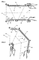
- This invention applies to ducts having utility in gas turbine engines in general, and to cooled ducts in particular.
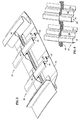
- the cooled exhaust duct further includes a plurality of baffles extending between adjacent bands.
- the baffles compartmentalize the circumferentially extending compartment, in which they are disposed, into a plurality of sub-compartments that inhibit circumferential travel of cooling air flow.
Landscapes
- Engineering & Computer Science (AREA)
- Chemical & Material Sciences (AREA)
- Combustion & Propulsion (AREA)
- Mechanical Engineering (AREA)
- General Engineering & Computer Science (AREA)
- Turbine Rotor Nozzle Sealing (AREA)
Claims (13)
- Gekühltes Auslassrohr (10), das eine axiale Mittellinie (18) aufweist, umfassend:einen internen Bereich (20), der zwischen einer ersten Wand (24) und einer zweiten Wand (26) angeordnet ist, wobei sich der interne Bereich entlang der axialen Mittellinie (18) erstreckt, wobei die erste Wand (24) radial innenseitig der zweiten Wand (26) angeordnet ist; undeine Mehrzahl von radial erweiterbaren Bändern (22), die sich jeweils innerhalb des inneren Bereichs (20) erstrecken und axial voneinander beabstandet sind, wobei die Bänder an der ersten Wand (24) und der zweiten Wand (26) angebracht sind und betreibbar sind, eine relative Positionsänderung zwischen der ersten Wand (24) und der zweiten Wand (26) aufzunehmen;dadurch gekennzeichnet, dass das gekühlte Auslassrohr (10) des Weiteren umfasst:eine Mehrzahl von Ablenkplatten (40), die sich in Längsrichtung zwischen benachbarten radial erweiterbaren Bändern (22) und in Höhenrichtung zwischen der ersten Wand (24) und der zweiten Wand (26) erstrecken.
- Gekühltes Auslassrohr nach Anspruch 1, wobei jedes Band (22) einen ersten Bereich (32), der an der ersten Wand (24) angebracht ist, einen zweiten Bereich (34), der an der zweiten Wand (26) angebracht ist, und einen Zwischenbereich beinhaltet, der mit dem ersten und dem zweiten Bereich (32, 34) verbunden ist.
- Gekühltes Auslassrohr nach Anspruch 1 oder 2, wobei die radial erweiterbaren Bänder (22) Aussparungen (42) beinhalten und die Ablenkplatten (40) innerhalb der Aussparungen (42) angeordnet sind.
- Gekühltes Auslassrohr nach Anspruch 3, wobei sich die Ablenkplatten (40) in Längsrichtung im Wesentlichen parallel zu der axialen Mittellinie (18) erstrecken.
- Gekühltes Auslassrohr nach einem der vorangehenden Ansprüche, wobei die Ablenkplatten (40) und die Bänder (22) im Wesentlichen orthogonal angeordnet sind.
- Gekühltes Auslassrohr nach Anspruch 1, wobei das gekühlte Auslassrohr des Weiteren einen Umfang aufweist, und wobei:der innere Bereich ein Ring (20) ist, der zwischen einer ersten Wand (24) und einer zweiten Wand (26) angeordnet ist, wobei sich der Ring entlang der axialen Mittellinie (18) erstreckt; undwobei sich jedes der Mehrzahl von radial erweiterbaren Bändern (22) umfangsmäßig innerhalb des Rings (30) erstreckt.
- Gekühltes Auslassrohr nach Anspruch 6, wobei jedes Band (22) einen ersten Bereich (32), der an der ersten Wand (24) angebracht ist, einen zweiten Bereich (34), der an der zweiten Wand (26) angebracht ist, und einen Zwischenbereich (36) beinhaltet, der mit dem ersten und dem zweiten Bereich (32, 34) verbunden ist.
- Gekühltes Auslassrohr nach Anspruch 7, wobei sich der Zwischenbereich (36) in etwa parallel zu der axialen Mittellinie (18) erstreckt.
- Gekühltes Auslassrohr nach einem der Ansprüche 6 bis 8, wobei die radial erweiterbaren Bänder (22) Aussparungen (42) beinhalten, und die Ablenkplatten (40) innerhalb der Aussparungen (42) angeordnet sind.
- Gekühltes Auslassrohr nach Anspruch 9, wobei sich die Ablenkplatten (40) in Längsrichtung im Wesentlichen parallel zu der axialen Mittellinie (18) erstrecken.
- Gekühltes Auslassrohr nach einem der Ansprüche 6 bis 10, wobei die Ablenkplatten (40) und die Bänder (22) im Wesentlichen orthogonal angeordnet sind.
- Gekühltes Auslassrohr nach einem der Ansprüche 6 bis 11, wobei zumindest eine der Mehrzahl von Ablenkplatten ein Versteifungsmittel (44) beinhaltet.
- Gekühltes Auslassrohr nach einem der Ansprüche 6 bis 11, des Weiteren umfassend ein oder mehrere Gelenke (46) in zumindest einer der Mehrzahl von Ablenkplatten (40).
Applications Claiming Priority (2)
| Application Number | Priority Date | Filing Date | Title |
|---|---|---|---|
| US11/000,829 US7631481B2 (en) | 2004-12-01 | 2004-12-01 | Cooled duct for gas turbine engine |
| PCT/GB2005/004617 WO2006059119A1 (en) | 2004-12-01 | 2005-12-01 | Cooled duct for gas turbine engine |
Publications (2)
| Publication Number | Publication Date |
|---|---|
| EP1817490A1 EP1817490A1 (de) | 2007-08-15 |
| EP1817490B1 true EP1817490B1 (de) | 2012-08-01 |
Family
ID=35759237
Family Applications (1)
| Application Number | Title | Priority Date | Filing Date |
|---|---|---|---|
| EP05811553A Expired - Lifetime EP1817490B1 (de) | 2004-12-01 | 2005-12-01 | Gekühlter Abgaskanal |
Country Status (6)
| Country | Link |
|---|---|
| US (1) | US7631481B2 (de) |
| EP (1) | EP1817490B1 (de) |
| JP (1) | JP2008522096A (de) |
| KR (1) | KR20070086215A (de) |
| TW (1) | TW200702549A (de) |
| WO (1) | WO2006059119A1 (de) |
Families Citing this family (21)
| Publication number | Priority date | Publication date | Assignee | Title |
|---|---|---|---|---|
| US7430867B2 (en) * | 2004-01-21 | 2008-10-07 | Rolls-Royce Plc | Gas turbine multiple sectioned exhaust duct |
| US20060137352A1 (en) * | 2004-12-29 | 2006-06-29 | United Technologies Corporation | Augmentor liner |
| US7975488B2 (en) * | 2006-07-28 | 2011-07-12 | United Technologies Corporation | Low profile attachment hanger system for a cooling liner within a gas turbine engine swivel exhaust duct |
| US7814753B2 (en) * | 2006-07-25 | 2010-10-19 | United Technologies Corporation | Low profile attachment hanger system for a cooling liner within a gas turbine engine swivel exhaust duct |
| DE102007050664A1 (de) * | 2007-10-24 | 2009-04-30 | Man Turbo Ag | Brenner für eine Strömungsmaschine, Leitblech für einen derartigen Brenner sowie eine Strömungsmaschine mit einem derartigen Brenner |
| US8127526B2 (en) * | 2008-01-16 | 2012-03-06 | United Technologies Corporation | Recoatable exhaust liner cooling arrangement |
| US8122722B2 (en) * | 2008-02-29 | 2012-02-28 | General Electric Company | Exhaust nozzle seal with segmented basesheet disposed between side rails |
| US9297335B2 (en) * | 2008-03-11 | 2016-03-29 | United Technologies Corporation | Metal injection molding attachment hanger system for a cooling liner within a gas turbine engine swivel exhaust duct |
| DE102008023052B4 (de) * | 2008-05-09 | 2011-02-10 | Eads Deutschland Gmbh | Brennkammerwand bzw. Heißgaswand einer Brennkammer und Brennkammer mit einer Brennkammerwand |
| RU2530685C2 (ru) * | 2010-03-25 | 2014-10-10 | Дженерал Электрик Компани | Структуры ударного воздействия для систем охлаждения |
| US10436063B2 (en) | 2012-08-17 | 2019-10-08 | United Technologies Corporation | Assembly for mounting a turbine engine to an airframe |
| WO2014109758A1 (en) | 2013-01-11 | 2014-07-17 | United Technologies Corporation | Serpentine baffle for a gas turbine engine exhaust duct |
| US9080447B2 (en) * | 2013-03-21 | 2015-07-14 | General Electric Company | Transition duct with divided upstream and downstream portions |
| US10704424B2 (en) * | 2013-11-04 | 2020-07-07 | Raytheon Technologies Corporation | Coated cooling passage |
| US9896970B2 (en) * | 2014-11-14 | 2018-02-20 | General Electric Company | Method and system for sealing an annulus |
| EP3181455B1 (de) | 2015-12-16 | 2019-04-17 | AIRBUS HELICOPTERS DEUTSCHLAND GmbH | Flugzeug mit heisser abluft mit zwei schwenkbar gelagerten abgasabschnitten |
| GB201803483D0 (en) * | 2018-03-05 | 2018-04-18 | Rolls Royce Plc | Aircraft nozzle |
| US11346253B2 (en) * | 2019-03-22 | 2022-05-31 | Raytheon Technologies Corporation | Liner apparatus and method of inspecting and/or cleaning a liner annular region |
| US11614233B2 (en) * | 2020-08-31 | 2023-03-28 | General Electric Company | Impingement panel support structure and method of manufacture |
| CN114687888B (zh) * | 2022-04-14 | 2024-01-30 | 中国航发沈阳发动机研究所 | 一种二元矢量喷管冷却结构 |
| CN116641809B (zh) * | 2023-06-16 | 2025-08-29 | 中国航发沈阳发动机研究所 | 一种发动机二元喷管 |
Family Cites Families (32)
| Publication number | Priority date | Publication date | Assignee | Title |
|---|---|---|---|---|
| US2874536A (en) * | 1954-03-18 | 1959-02-24 | Gen Electric | Cooling means for tailpipe |
| GB857345A (en) * | 1958-03-05 | 1960-12-29 | Havilland Engine Co Ltd | Duct assemblies |
| US3043103A (en) * | 1958-10-10 | 1962-07-10 | Gen Motors Corp | Liquid cooled wall |
| DE1481606A1 (de) * | 1966-03-03 | 1970-01-22 | Man Turbo Gmbh | Vorrichtung zur Betaetigung einer aus drei um ihre Laengsachsen gegeneinander verdrehbaren Rohrabschnitten bestehenden Strahlablenkvorrichtung |
| US3437173A (en) * | 1966-11-25 | 1969-04-08 | Gen Electric | Gas turbine engine with screech attenuating means |
| US3981448A (en) * | 1970-04-23 | 1976-09-21 | The Garrett Corporation | Cooled infrared suppressor |
| US3850261A (en) * | 1973-03-01 | 1974-11-26 | Gen Electric | Wide band width single layer sound suppressing panel |
| US3972475A (en) * | 1975-07-31 | 1976-08-03 | United Technologies Corporation | Nozzle construction providing for thermal growth |
| US4433751A (en) * | 1981-12-09 | 1984-02-28 | Pratt & Whitney Aircraft Of Canada Limited | Sound suppressor liner |
| GB2185718B (en) * | 1986-01-23 | 1989-11-01 | Rolls Royce | Exhaust nozzle for a gas turbine engine |
| US5557932A (en) * | 1986-06-06 | 1996-09-24 | The United States Of America As Represented By The Secretary Of The Air Force | Low thermal stress impingement cooling apparatus |
| US4718230A (en) * | 1986-11-10 | 1988-01-12 | United Technologies Corporation | Augmentor liner construction |
| US4864818A (en) * | 1988-04-07 | 1989-09-12 | United Technologies Corporation | Augmentor liner construction |
| US4887663A (en) * | 1988-05-31 | 1989-12-19 | United Technologies Corporation | Hot gas duct liner |
| US4944362A (en) * | 1988-11-25 | 1990-07-31 | General Electric Company | Closed cavity noise suppressor |
| US5076496A (en) * | 1990-02-05 | 1991-12-31 | General Electric Company | Exhaust nozzle flap seal |
| US5388765A (en) * | 1990-04-18 | 1995-02-14 | United Technologies Corporation | Gas turbine nozzle construction |
| DE69232222T2 (de) * | 1991-05-16 | 2002-08-22 | General Electric Co., Schenectady | Hitzeschild für achsymmetrische schwenkbare Schubdüse |
| FR2676779B1 (fr) * | 1991-05-21 | 1994-06-03 | Lair Jean Pierre | Tuyere a section variable. |
| US5201887A (en) * | 1991-11-26 | 1993-04-13 | United Technologies Corporation | Damper for augmentor liners |
| FR2691209B1 (fr) * | 1992-05-18 | 1995-09-01 | Europ Propulsion | Enceinte contenant des gaz chauds refroidie par transpiration, notamment chambre propulsive de moteur-fusee, et procede de fabrication. |
| DE69526615T2 (de) * | 1994-09-14 | 2002-11-28 | Mitsubishi Jukogyo K.K., Tokio/Tokyo | Wandaufbau für die Austrittsdüse eines Überschall-Strahltriebwerks |
| US5839663A (en) * | 1996-07-23 | 1998-11-24 | United Technologies Corporation | Gas turbine exhaust nozzle flap and flap seal apparatus |
| GB9623615D0 (en) * | 1996-11-13 | 1997-07-09 | Rolls Royce Plc | Jet pipe liner |
| US6199371B1 (en) * | 1998-10-15 | 2001-03-13 | United Technologies Corporation | Thermally compliant liner |
| US6415599B1 (en) * | 2001-05-11 | 2002-07-09 | General Electric Company | Engine interface for axisymmetric vectoring nozzle |
| US7188417B2 (en) * | 2002-06-28 | 2007-03-13 | United Technologies Corporation | Advanced L-channel welded nozzle design |
| ES2224807B1 (es) * | 2002-08-14 | 2007-05-01 | Sener, Ingenieria Y Sistemas, S.A. | Conducto de reduccion de ruido para componentes estaticos de motores aeronauticos. |
| US7430867B2 (en) * | 2004-01-21 | 2008-10-07 | Rolls-Royce Plc | Gas turbine multiple sectioned exhaust duct |
| US20060137352A1 (en) * | 2004-12-29 | 2006-06-29 | United Technologies Corporation | Augmentor liner |
| US7739872B2 (en) * | 2005-02-14 | 2010-06-22 | United Technologies Corporation | Cooled dual wall liner closeout |
| US7581399B2 (en) * | 2006-01-05 | 2009-09-01 | United Technologies Corporation | Damped coil pin for attachment hanger hinge |
-
2004
- 2004-12-01 US US11/000,829 patent/US7631481B2/en active Active
-
2005
- 2005-12-01 KR KR1020077013474A patent/KR20070086215A/ko not_active Ceased
- 2005-12-01 TW TW094142255A patent/TW200702549A/zh unknown
- 2005-12-01 EP EP05811553A patent/EP1817490B1/de not_active Expired - Lifetime
- 2005-12-01 WO PCT/GB2005/004617 patent/WO2006059119A1/en not_active Ceased
- 2005-12-01 JP JP2007543918A patent/JP2008522096A/ja active Pending
Also Published As
| Publication number | Publication date |
|---|---|
| KR20070086215A (ko) | 2007-08-27 |
| WO2006059119A1 (en) | 2006-06-08 |
| US20060112676A1 (en) | 2006-06-01 |
| EP1817490A1 (de) | 2007-08-15 |
| JP2008522096A (ja) | 2008-06-26 |
| US7631481B2 (en) | 2009-12-15 |
| TW200702549A (en) | 2007-01-16 |
Similar Documents
| Publication | Publication Date | Title |
|---|---|---|
| EP1817490B1 (de) | Gekühlter Abgaskanal | |
| EP2927428B1 (de) | Gekühltes schaufelblatt eines turbinenmotors | |
| CA2327857C (en) | Turbine nozzle with sloped film cooling | |
| EP2870324B1 (de) | Gewellter wärmestrahlungsschutzschirm für einen mittelturbinenrahmen | |
| US10641122B2 (en) | Tip clearance control for turbine blades | |
| EP3396107B1 (de) | Umlenkkappe und zugehörige leitschaufel | |
| EP3040519B1 (de) | Spitzenabstandssteuerung für turbinenschaufeln | |
| EP2236750B1 (de) | Agencement de refroidissement par projection pour moteur à turbine à gaz | |
| EP2948636B1 (de) | Gasturbinenmotorkomponente mit konturiertem rippenende | |
| EP3399149B1 (de) | Umlenkkappen für schaufeln in gasturbinentriebwerken | |
| WO2012134816A1 (en) | Turbine combustion system liner | |
| US8328511B2 (en) | Prechorded turbine nozzle | |
| US20160319698A1 (en) | Blade outer air seal cooling passage | |
| US11268443B2 (en) | Turbine engine nacelle comprising a cooling device | |
| US2884759A (en) | Combustion chamber construction | |
| EP3048282B1 (de) | Gasturbinenmotor und blockiertüranordnung | |
| US10975770B1 (en) | Integral engine case precooler | |
| RU2382279C2 (ru) | Камера сгорания газотурбинного двигателя | |
| US9650904B1 (en) | Transition duct system with straight ceramic liner for delivering hot-temperature gases in a combustion turbine engine | |
| US11686215B2 (en) | Assembly for turbine | |
| EP2943654B1 (de) | Auskleidungsanordnung für eine gasturbine | |
| GB2628854A (en) | HEX strut arrangement |
Legal Events
| Date | Code | Title | Description |
|---|---|---|---|
| PUAI | Public reference made under article 153(3) epc to a published international application that has entered the european phase |
Free format text: ORIGINAL CODE: 0009012 |
|
| 17P | Request for examination filed |
Effective date: 20070522 |
|
| AK | Designated contracting states |
Kind code of ref document: A1 Designated state(s): DE FR GB IT |
|
| RBV | Designated contracting states (corrected) |
Designated state(s): DE FR GB IT |
|
| RIN1 | Information on inventor provided before grant (corrected) |
Inventor name: PAUL, STEPHEN, A. Inventor name: KEHRET, DEBORAH, F. Inventor name: FARAH, JORGE, I. Inventor name: MURPHEY, MICHAEL Inventor name: SCOTT, RICHARD Inventor name: COWAN, CURTIS, C. Inventor name: LAVIN, JEFFREY, R. Inventor name: KEYSA, STANLEY |
|
| DAX | Request for extension of the european patent (deleted) | ||
| 17Q | First examination report despatched |
Effective date: 20090703 |
|
| GRAP | Despatch of communication of intention to grant a patent |
Free format text: ORIGINAL CODE: EPIDOSNIGR1 |
|
| RTI1 | Title (correction) |
Free format text: COOLED EXHAUST DUCT |
|
| GRAS | Grant fee paid |
Free format text: ORIGINAL CODE: EPIDOSNIGR3 |
|
| GRAA | (expected) grant |
Free format text: ORIGINAL CODE: 0009210 |
|
| AK | Designated contracting states |
Kind code of ref document: B1 Designated state(s): DE FR GB IT |
|
| REG | Reference to a national code |
Ref country code: GB Ref legal event code: FG4D |
|
| REG | Reference to a national code |
Ref country code: DE Ref legal event code: R096 Ref document number: 602005035451 Country of ref document: DE Effective date: 20121011 |
|
| PGFP | Annual fee paid to national office [announced via postgrant information from national office to epo] |
Ref country code: DE Payment date: 20121128 Year of fee payment: 8 |
|
| PGFP | Annual fee paid to national office [announced via postgrant information from national office to epo] |
Ref country code: GB Payment date: 20121128 Year of fee payment: 8 Ref country code: IT Payment date: 20121212 Year of fee payment: 8 |
|
| PLBE | No opposition filed within time limit |
Free format text: ORIGINAL CODE: 0009261 |
|
| STAA | Information on the status of an ep patent application or granted ep patent |
Free format text: STATUS: NO OPPOSITION FILED WITHIN TIME LIMIT |
|
| 26N | No opposition filed |
Effective date: 20130503 |
|
| REG | Reference to a national code |
Ref country code: DE Ref legal event code: R097 Ref document number: 602005035451 Country of ref document: DE Effective date: 20130503 |
|
| REG | Reference to a national code |
Ref country code: FR Ref legal event code: ST Effective date: 20130830 |
|
| PG25 | Lapsed in a contracting state [announced via postgrant information from national office to epo] |
Ref country code: FR Free format text: LAPSE BECAUSE OF NON-PAYMENT OF DUE FEES Effective date: 20130102 |
|
| REG | Reference to a national code |
Ref country code: DE Ref legal event code: R119 Ref document number: 602005035451 Country of ref document: DE |
|
| GBPC | Gb: european patent ceased through non-payment of renewal fee |
Effective date: 20131201 |
|
| REG | Reference to a national code |
Ref country code: DE Ref legal event code: R119 Ref document number: 602005035451 Country of ref document: DE Effective date: 20140701 |
|
| PG25 | Lapsed in a contracting state [announced via postgrant information from national office to epo] |
Ref country code: DE Free format text: LAPSE BECAUSE OF NON-PAYMENT OF DUE FEES Effective date: 20140701 |
|
| PG25 | Lapsed in a contracting state [announced via postgrant information from national office to epo] |
Ref country code: GB Free format text: LAPSE BECAUSE OF NON-PAYMENT OF DUE FEES Effective date: 20131201 |
|
| PG25 | Lapsed in a contracting state [announced via postgrant information from national office to epo] |
Ref country code: IT Free format text: LAPSE BECAUSE OF NON-PAYMENT OF DUE FEES Effective date: 20131231 |
|
| PG25 | Lapsed in a contracting state [announced via postgrant information from national office to epo] |
Ref country code: IT Free format text: LAPSE BECAUSE OF NON-PAYMENT OF DUE FEES Effective date: 20131201 |