EP1817143B2 - Shaving implement - Google Patents
Shaving implement Download PDFInfo
- Publication number
- EP1817143B2 EP1817143B2 EP05804456.1A EP05804456A EP1817143B2 EP 1817143 B2 EP1817143 B2 EP 1817143B2 EP 05804456 A EP05804456 A EP 05804456A EP 1817143 B2 EP1817143 B2 EP 1817143B2
- Authority
- EP
- European Patent Office
- Prior art keywords
- skin
- guard
- arcuate channels
- razor
- razor cartridge
- Prior art date
- Legal status (The legal status is an assumption and is not a legal conclusion. Google has not performed a legal analysis and makes no representation as to the accuracy of the status listed.)
- Active
Links
- 239000000463 material Substances 0.000 claims abstract description 10
- 229920001971 elastomer Polymers 0.000 claims description 3
- 239000005060 rubber Substances 0.000 claims description 3
- 239000006260 foam Substances 0.000 claims description 2
- 239000012815 thermoplastic material Substances 0.000 claims description 2
- 229920001187 thermosetting polymer Polymers 0.000 claims description 2
- XLYOFNOQVPJJNP-UHFFFAOYSA-N water Substances O XLYOFNOQVPJJNP-UHFFFAOYSA-N 0.000 abstract description 10
- 210000004209 hair Anatomy 0.000 description 5
- 230000000694 effects Effects 0.000 description 4
- 150000001875 compounds Chemical class 0.000 description 1
- 230000001419 dependent effect Effects 0.000 description 1
- 239000010408 film Substances 0.000 description 1
- 230000001788 irregular Effects 0.000 description 1
- 239000000314 lubricant Substances 0.000 description 1
- 230000004048 modification Effects 0.000 description 1
- 238000012986 modification Methods 0.000 description 1
- 229920003052 natural elastomer Polymers 0.000 description 1
- 229920001194 natural rubber Polymers 0.000 description 1
- 239000003921 oil Substances 0.000 description 1
- 239000008257 shaving cream Substances 0.000 description 1
- 229920003051 synthetic elastomer Polymers 0.000 description 1
- 239000005061 synthetic rubber Substances 0.000 description 1
- 239000010409 thin film Substances 0.000 description 1
Images


Classifications
-
- B—PERFORMING OPERATIONS; TRANSPORTING
- B26—HAND CUTTING TOOLS; CUTTING; SEVERING
- B26B—HAND-HELD CUTTING TOOLS NOT OTHERWISE PROVIDED FOR
- B26B21/00—Razors of the open or knife type; Safety razors or other shaving implements of the planing type; Hair-trimming devices involving a razor-blade; Equipment therefor
- B26B21/40—Details or accessories
- B26B21/4012—Housing details, e.g. for cartridges
- B26B21/4018—Guard elements
-
- B—PERFORMING OPERATIONS; TRANSPORTING
- B26—HAND CUTTING TOOLS; CUTTING; SEVERING
- B26B—HAND-HELD CUTTING TOOLS NOT OTHERWISE PROVIDED FOR
- B26B21/00—Razors of the open or knife type; Safety razors or other shaving implements of the planing type; Hair-trimming devices involving a razor-blade; Equipment therefor
- B26B21/08—Razors of the open or knife type; Safety razors or other shaving implements of the planing type; Hair-trimming devices involving a razor-blade; Equipment therefor involving changeable blades
- B26B21/14—Safety razors with one or more blades arranged transversely to the handle
- B26B21/22—Safety razors with one or more blades arranged transversely to the handle involving several blades to be used simultaneously
- B26B21/222—Safety razors with one or more blades arranged transversely to the handle involving several blades to be used simultaneously with the blades moulded into, or attached to, a changeable unit
-
- B—PERFORMING OPERATIONS; TRANSPORTING
- B26—HAND CUTTING TOOLS; CUTTING; SEVERING
- B26B—HAND-HELD CUTTING TOOLS NOT OTHERWISE PROVIDED FOR
- B26B21/00—Razors of the open or knife type; Safety razors or other shaving implements of the planing type; Hair-trimming devices involving a razor-blade; Equipment therefor
- B26B21/40—Details or accessories
- B26B21/4012—Housing details, e.g. for cartridges
Definitions
- This invention relates generally to razor cartridges and, more particularly, to guards disposed on razor cartridges.
- Conventional wet shaving systems include a handle and a razor cartridge.
- razor cartridges have several skin-engaging elements mounted on a frame, the skin-engaging elements including at least one razor blade, a guard, and a cap.
- the razor cartridge and the handle are formed as a single, unitary piece.
- the razor cartridge and handle in these "disposable razor units" are used together until the razor blades are dulled. Once worn, the entire disposable razor unit is discarded and a new disposable razor unit is used in place of the discarded one.
- the razor cartridge is removably attached to a reusable handle. In these applications, the razor cartridge is attached to the handle and used until the blades are dulled. The user then selectively replaces the worn razor cartridge with a new one on the same handle for continued shaving.
- the skin-engaging elements are positioned on the frame such that the guard is forward of the blades and the cap is aft of the blades.
- the terms "forward” and “aft,” as used herein, define the relative position between features of the razor cartridge.
- a skin-engaging element “forward” of the blades is positioned such that the surface to be shaved encounters that feature prior to encountering the blades during normal shaving operation.
- a skin-engaging element "aft" of the blades is positioned such that the surface to be shaved encounters that feature only after encountering the blades during normal shaving.
- the known razor head comprises at least one blade and a guard element in front of the blades.
- the guard element is advantageously formed with a material comprising a high coefficient of friction, e.g. rubber or rubber type compounds, in order to stretch the skin before it encounters the sharp edges of the blades.
- the forward guard element also comprises an irregular surface in order to provide better gripping of the skin surface prior to contact with the blades.
- US-A-5 689 883 discloses a shaving element comprising a shaving head which includes a skin-contacting element, in the form of a plurality of sections of flexible ridges. The ridges are arranged in a herringbone pattern and thus are divided into a plurality of adjacent segments.
- a guard having the features of the preamble of claim 1 is known from WO-A-2005/08284 .
- the present invention is directed to a guard for a razor cartridge as defined in claim 1.
- the present invention is directed to a razor cartridge which is provided as defined in claim 9.
- the present invention is directed to a wet shaving system which is provided as defined in claim 19.
- the dependent claims relate to individual embodiments of the invention.
- the arcuate channels facilitate the close cutting of the hairs to be shaved. Because the arcuate shape is convex in the direction in which the guard of the present invention is stroked, the skin is stretched in the direction of the shaving stroke and outward towards the ends of the frame. By stretching the skin in this manner, the skin is pulled taught, thereby allowing the skin to be flattened and the hairs to be more erectly positioned in preparation for being cut.
- Another advantage of the present invention is that the arcuate channels trap water and shaving aid on the skin surface during the shaving operation. By doing so, a leveling effect is realized with regard to the skin surface. Accordingly, a thin, uniform film of water and/or shaving aid is left on the skin surface for the razor blades to slide over, which thereby provides a smooth shave.
- the arcuate shape of the channels allows the trapped water and/or shaving aid to be distributed along the lengths thereof.
- the forward movement of the stroke allows the water and/or shaving aid to be forced back through the channels in the directions of the points at which the channels terminate.
- Shaving debris e.g., cut whiskers and the like
- System 10 comprises a razor cartridge 12 attached to a handle 14.
- the cartridge 12 may be permanently attached to the handle 14, or it may be removably connected to the handle to allow the razor cartridge to be changed when the hair cutting devices thereof (hereinafter referred to as razor blades, although other devices are within the scope of the invention) become dulled and warrant replacement.
- the cartridge 12 may be pivotally attached or connected to the handle 14 to allow for the pivotal movement of the razor blades relative to the skin surface to be shaved.
- the cartridge 12 comprises a frame 16 that defines a plurality of skin-engaging elements.
- the skin-engaging elements generally facilitate the functions associated with a shaving operation, namely, stretching the skin in preparation for shaving, applying a lubricant or other skin-conditioning aid to the skin, and removing oils, shaving debris, and/or excess water from the skin surface.
- the skin-engaging elements comprise a guard 18, a cap 20, and at least one razor blade 22.
- the guard 18 forms a forward portion of the cartridge 12 and is positioned forward of the razor blades 22.
- the cap 20 forms an aft portion of the cartridge 12 and is positioned behind the razor blades 22.
- the razor blades 22 are mounted longitudinally in the opening over a length "L" of the cartridge 12, each razor blade 22 having a sharpened edge 26 suitable for cutting hair.
- the guard 18 extends at least part way across the length L of the cartridge 12 and includes a skin-engaging surface 28 and one or more channels 30 that extend lengthwise on an upper surface of the skin-engaging surface.
- the channels 30 are arcuate in shape such that the midpoints of the channels substantially correspond to the midpoints of the razor blades 22.
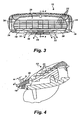
- the ends of the channels 30 extend back towards the sides or end walls 24 of the frame 16 to stretch the skin by a desired amount in the directions indicated by arrows 32 ( FIG. 3 ) prior to the cutting edges 26 of the razor blades 22 engaging the hairs.
- Several channels 30 are preferably disposed on the guard 18, each having a radius that progressively varies in the forward-to-aft direction.
- the channels 30 may be cut, etched, molded into, or otherwise suitably formed in the surface of the guard 18.
- the channels 30 each have a width "w,” which may either be the same or different for each channel, and which may either be the same or different along the length of each channel.
- Each channel 30 also has a depth "d,” which, as with the width w, may be the same or different for each channel and which may either by the same or different along the length of each channel.
- the width w and the depth d are sufficient to trap excess water and/or shaving aid applied to the skin prior to shaving and to redistribute such water and/or shaving aid during a shaving stroke.
- the skin-engaging surface is pressed against the surface being shaved, a leveling effect is realized, thereby allowing a thin film of water and/or shaving aid to be distributed over the skin during a shaving stroke.
- the width w and depth d may be sufficient to allow shaving debris to be removed from the skin and either pushed to the sides of the cartridge 12 or at least evenly distributed in front of the blades 22.
- each channel is also separated from adjacent channels by a distance "D," which, as with the width w and depth d, may be the same or may vary.
- the guard 18 is manufactured from any suitable flexible material.
- suitable flexible materials include, but are not limited to, elastomeric materials such as natural or synthetic rubbers and the like, foams, thermoplastic materials of appropriate flexibility, thermoset materials, and combinations of the foregoing materials.
- a guard of a razor cartridge may include two or more sets of arcuately-shaped channels.
- a cartridge 112 is shown in which a guard 118 is shown in which two sets of arcuately-shaped channels are positioned on an upper surface thereof.
- the first set (shown at 130) is positioned on one side of the guard 118, while the second set (shown at 131) is positioned on the other side of the guard 118.
- the space "s" defined between the first set 130 and the second set 131 is dimensioned to provide optimal skin-stretching effects during a shaving operation. Referring now to FIG.
- a razor cartridge 212 having a guard 218 is shown in which three sets of arcuately-shaped channels are positioned on an upper surface thereof. Each set (shown at 230, 231, and 233, respectively) is positioned such that during a shaving operation, an optimal skin-stretching effect is provided. In any embodiment of a razor cartridge in which two or more sets of arcuate channels are utilized, the sets may be equidistantly positioned on the skin-engaging surface.
Abstract
Description
- This invention relates generally to razor cartridges and, more particularly, to guards disposed on razor cartridges.
- Conventional wet shaving systems include a handle and a razor cartridge. Typically, razor cartridges have several skin-engaging elements mounted on a frame, the skin-engaging elements including at least one razor blade, a guard, and a cap. In some embodiments, the razor cartridge and the handle are formed as a single, unitary piece. The razor cartridge and handle in these "disposable razor units" are used together until the razor blades are dulled. Once worn, the entire disposable razor unit is discarded and a new disposable razor unit is used in place of the discarded one. In other embodiments, the razor cartridge is removably attached to a reusable handle. In these applications, the razor cartridge is attached to the handle and used until the blades are dulled. The user then selectively replaces the worn razor cartridge with a new one on the same handle for continued shaving.
- In a typical razor cartridge, the skin-engaging elements are positioned on the frame such that the guard is forward of the blades and the cap is aft of the blades. The terms "forward" and "aft," as used herein, define the relative position between features of the razor cartridge. A skin-engaging element "forward" of the blades is positioned such that the surface to be shaved encounters that feature prior to encountering the blades during normal shaving operation. Conversely, a skin-engaging element "aft" of the blades is positioned such that the surface to be shaved encounters that feature only after encountering the blades during normal shaving.
- One known razor head is described in
EP-A-1 184 141 . The known razor head comprises at least one blade and a guard element in front of the blades. The guard element is advantageously formed with a material comprising a high coefficient of friction, e.g. rubber or rubber type compounds, in order to stretch the skin before it encounters the sharp edges of the blades. The forward guard element also comprises an irregular surface in order to provide better gripping of the skin surface prior to contact with the blades. - Further
US-A-5 689 883 discloses a shaving element comprising a shaving head which includes a skin-contacting element, in the form of a plurality of sections of flexible ridges. The ridges are arranged in a herringbone pattern and thus are divided into a plurality of adjacent segments.
A guard having the features of the preamble of claim 1 is known fromWO-A-2005/08284 - During a use of typical razor cartridge, some surfaces to be shaved are often too fleshy or fatty, which results in excess skin flow over the razor blades. When the skin flow over the blades exceeds the capabilities of the razor, the skin is nicked or cut. One way to avoid this type of overflow condition is to pull the skin in front of the razor blades taut during the shaving operation using the fingers of the free hand. However, pulling the skin taut with the fingers is not always possible or desirable, as the skin surface is typically coated with shaving aid.
- It would be desirable to provide a shaving implement having a guard with a surface formed of flexible skin-engaging members to pre-stretch the skin prior to being shaved by the razor blade.
- It would also be desirable to provide an array of skin-engaging members on the guard which act to trap and evenly redistribute water and shaving aid (e.g., shaving cream) forward of the blades.
- In one aspect, the present invention is directed to a guard for a razor cartridge as defined in claim 1.
- In a second aspect, the present invention is directed to a razor cartridge which is provided as defined in claim 9.
- In a third aspect, the present invention is directed to a wet shaving system which is provided as defined in claim 19. The dependent claims relate to individual embodiments of the invention.
- One advantage of the present invention is that the arcuate channels facilitate the close cutting of the hairs to be shaved. Because the arcuate shape is convex in the direction in which the guard of the present invention is stroked, the skin is stretched in the direction of the shaving stroke and outward towards the ends of the frame. By stretching the skin in this manner, the skin is pulled taught, thereby allowing the skin to be flattened and the hairs to be more erectly positioned in preparation for being cut.
- Another advantage of the present invention is that the arcuate channels trap water and shaving aid on the skin surface during the shaving operation. By doing so, a leveling effect is realized with regard to the skin surface. Accordingly, a thin, uniform film of water and/or shaving aid is left on the skin surface for the razor blades to slide over, which thereby provides a smooth shave.
- Another advantage is that the arcuate shape of the channels allows the trapped water and/or shaving aid to be distributed along the lengths thereof. As a shaving stroke is executed, the forward movement of the stroke allows the water and/or shaving aid to be forced back through the channels in the directions of the points at which the channels terminate. Shaving debris (e.g., cut whiskers and the like) may also be directed through the channels and away from the cutting edges of the razor blades.
-
-
FIG. 1 is a perspective view of a cartridge with a guard of the present invention mounted on a handle. -
FIG. 2 is a perspective view of the cartridge ofFIG. 1 . -
FIG. 3 is a front view of the cartridge ofFIG. 1 . -
FIG. 4 is a sectional view of the cartridge ofFIG. 1 . -
FIG. 5 is a sectional view depicting one embodiment of the guard of the present invention. -
FIG. 6 is a sectional view depicting one embodiment of the guard of the present invention. - Referring to
FIG. 1 , a wet-shave razor system is shown generally at 10 and is hereinafter referred to as "system 10."System 10 comprises arazor cartridge 12 attached to ahandle 14. Thecartridge 12 may be permanently attached to thehandle 14, or it may be removably connected to the handle to allow the razor cartridge to be changed when the hair cutting devices thereof (hereinafter referred to as razor blades, although other devices are within the scope of the invention) become dulled and warrant replacement. In either configuration, thecartridge 12 may be pivotally attached or connected to thehandle 14 to allow for the pivotal movement of the razor blades relative to the skin surface to be shaved. - Referring now to
FIGS. 2 and3 , thecartridge 12 comprises aframe 16 that defines a plurality of skin-engaging elements. The skin-engaging elements generally facilitate the functions associated with a shaving operation, namely, stretching the skin in preparation for shaving, applying a lubricant or other skin-conditioning aid to the skin, and removing oils, shaving debris, and/or excess water from the skin surface. The skin-engaging elements comprise aguard 18, acap 20, and at least onerazor blade 22. Theguard 18 forms a forward portion of thecartridge 12 and is positioned forward of therazor blades 22. Thecap 20 forms an aft portion of thecartridge 12 and is positioned behind therazor blades 22. Theguard 18 and thecap 20, which may be joined together at end surfaces thereof or respectively joined todiscrete end walls 24, define an opening. Therazor blades 22 are mounted longitudinally in the opening over a length "L" of thecartridge 12, eachrazor blade 22 having a sharpenededge 26 suitable for cutting hair. Although the description hereinafter refers to razor blades in the plural, it should be understood that the present invention may utilize only one razor blade. - The
guard 18 extends at least part way across the length L of thecartridge 12 and includes a skin-engaging surface 28 and one ormore channels 30 that extend lengthwise on an upper surface of the skin-engaging surface. Thechannels 30 are arcuate in shape such that the midpoints of the channels substantially correspond to the midpoints of therazor blades 22. The ends of thechannels 30 extend back towards the sides orend walls 24 of theframe 16 to stretch the skin by a desired amount in the directions indicated by arrows 32 (FIG. 3 ) prior to thecutting edges 26 of therazor blades 22 engaging the hairs.Several channels 30 are preferably disposed on theguard 18, each having a radius that progressively varies in the forward-to-aft direction. Thechannels 30 may be cut, etched, molded into, or otherwise suitably formed in the surface of theguard 18. - As can be best seen in
FIG. 4 , thechannels 30 each have a width "w," which may either be the same or different for each channel, and which may either be the same or different along the length of each channel. Eachchannel 30 also has a depth "d," which, as with the width w, may be the same or different for each channel and which may either by the same or different along the length of each channel. In anychannel 30, the width w and the depth d are sufficient to trap excess water and/or shaving aid applied to the skin prior to shaving and to redistribute such water and/or shaving aid during a shaving stroke. Also, because the skin-engaging surface is pressed against the surface being shaved, a leveling effect is realized, thereby allowing a thin film of water and/or shaving aid to be distributed over the skin during a shaving stroke. Furthermore, the width w and depth d may be sufficient to allow shaving debris to be removed from the skin and either pushed to the sides of thecartridge 12 or at least evenly distributed in front of theblades 22. - In embodiments in which two or
more channels 30 are employed, each channel is also separated from adjacent channels by a distance "D," which, as with the width w and depth d, may be the same or may vary. - The
guard 18 is manufactured from any suitable flexible material. Suitable flexible materials that may be used include, but are not limited to, elastomeric materials such as natural or synthetic rubbers and the like, foams, thermoplastic materials of appropriate flexibility, thermoset materials, and combinations of the foregoing materials. - In alternative embodiments, a guard of a razor cartridge may include two or more sets of arcuately-shaped channels. Referring now to
FIG. 5 , acartridge 112 is shown in which aguard 118 is shown in which two sets of arcuately-shaped channels are positioned on an upper surface thereof. The first set (shown at 130) is positioned on one side of theguard 118, while the second set (shown at 131) is positioned on the other side of theguard 118. Preferably, the space "s" defined between thefirst set 130 and thesecond set 131 is dimensioned to provide optimal skin-stretching effects during a shaving operation. Referring now toFIG. 6 , arazor cartridge 212 having aguard 218 is shown in which three sets of arcuately-shaped channels are positioned on an upper surface thereof. Each set (shown at 230, 231, and 233, respectively) is positioned such that during a shaving operation, an optimal skin-stretching effect is provided. In any embodiment of a razor cartridge in which two or more sets of arcuate channels are utilized, the sets may be equidistantly positioned on the skin-engaging surface. - Although this invention has been shown and described with respect to the detailed embodiments thereof, it will be understood by those of skill in the art that various changes may be made and equivalents may be substituted for elements thereof without departing from the scope of the invention. In addition, modifications may be made to adapt a particular situation or material to the teachings of the invention without departing from the essential scope thereof. Therefore, it is intended that the invention not be limited to the particular embodiments disclosed in the above detailed description, but that the invention will include all embodiments falling within the scope of the appended claims.
Claims (17)
- A guard (18,118,218) for a razor cartridge (12,112,212) having at least one razor blade (22), the guard (18,118,218) including:- a skin-engaging surface (28), and- a plurality of arcuate channels (30,130,131,230,231,233) formed in the skin-engaging surface (28), each channel (30,130,131,230,231,233) having two ends,- wherein at least one of the arcuate channels (30,130,131,230,231,233) has a radius that varies from at least one other of the arcuate channels (30,130,131, 230,231,233),characterized in that- the ends of each of the arcuate channels (30,130,131,230,231,233) extend back towards the opposing ends of the razor blade (22).
- The guard (18,118,218) of claim 1, wherein the skin-engaging surface (28) extends at least part way across a length (L) of the razor cartridge (12,112,212).
- The guard (18,118,218) of claim 1 or 2, wherein the arcuate channels (30,130,131,230,231,233) extend lengthwise on an upper surface of the skin-engaging surface (28).
- The guard (18,118,218) of any one of claims 1 to 3, wherein midpoints along a length of the arcuate channels (30,130,131,230,231,233) substantially correspond to a midpoint along a length of the razor blade (22).
- The guard (18,118,218) of any one of claims 1 to 4, wherein the arcuate channels (30,130,131,230,231,233) are cut, etched, or molded into the skin-engaging surface (28).
- The guard (18,118,218) of any one of claims 1 to 5, wherein the guard (18,118,218) is manufactured from a rubber, foam, a thermoplastic material, a thermoset material, or a combination of at least two of the foregoing materials.
- The guard (18,118,218) of any one of claims 1 to 6, wherein the plurality of arcuate channels (30,130,131,230,231,233) includes at least two sets of pluralities of arcuate channels (30,130,131,230,231,233).
- The guard (18,118,218) of claim 7, wherein the at least two sets of pluralities of arcuate channels (30,130,131,230,231, 233) are equidistantly positioned on the skin-engaging surface (28).
- A razor cartridge (12,112,212), including:- a plurality of skin-engaging elements mounted on a frame (16) having two ends, the skin-engaging elements including:- at least one blade (22) having a sharpened cutting edge (26),- a cap positioned aft of the at least one blade (22), and- a guard (18,118,218) according to any one of the preceding claims positioned forward of the at least one blade (22).
- The razor cartridge (12,112,212) of claim 9, wherein the two ends of the frame (16) are each defined by an end wall (24).
- The razor cartridge (12,112,212) of claim 9 or 10, wherein the arcuate channels (30,130,131,230,231,233) extend lengthwise on the skin-engaging surface (28).
- The razor cartridge (12,112,212) of any one of claims 9 to 11, wherein each of the arcuate channels (30,130,131,230,231,233) is defined by a curved channel having a midpoint along a length of said curved channel that corresponds substantival with a midpoint along a length of the guard (18,118,218) and opposing ends that extend rearward towards the two ends of the frame (16).
- The razor cartridge (12,112,212) of any one of claims 9 to 12, wherein the plurality of arcuate channels (30,130,131,230,231,233) includes at least two sets of pluralities of arcuate channels (30,130,131,230,231, 233).
- A wet shaving system (10), including:- a handle (14), and- a razor cartridge (12,112,212) according to any one of claims 9 to 13 mounted on the handle (14).
- The wet shaving system (10) of claim 14, wherein the razor cartridge (12,112,212) is removably mounted on the handle (14).
- The wet shaving system (10) of claim 14 or 15, wherein the razor cartridge (12,112,212) is pivotally mounted on the handle (14).
- The wet shaving system (10) of any one of claims 14 to 16, wherein the arcuate channels (30,130,131,230,231,233) extend lengthwise on the skin-engaging surface (28).
Priority Applications (1)
| Application Number | Priority Date | Filing Date | Title |
|---|---|---|---|
| PL05804456T PL1817143T5 (en) | 2004-10-05 | 2005-10-05 | Shaving implement |
Applications Claiming Priority (2)
| Application Number | Priority Date | Filing Date | Title |
|---|---|---|---|
| US61634204P | 2004-10-05 | 2004-10-05 | |
| PCT/US2005/035763 WO2006041885A1 (en) | 2004-10-05 | 2005-10-05 | Shaving implement |
Publications (3)
| Publication Number | Publication Date |
|---|---|
| EP1817143A1 EP1817143A1 (en) | 2007-08-15 |
| EP1817143B1 EP1817143B1 (en) | 2011-03-16 |
| EP1817143B2 true EP1817143B2 (en) | 2014-07-16 |
Family
ID=35789192
Family Applications (1)
| Application Number | Title | Priority Date | Filing Date |
|---|---|---|---|
| EP05804456.1A Active EP1817143B2 (en) | 2004-10-05 | 2005-10-05 | Shaving implement |
Country Status (8)
| Country | Link |
|---|---|
| US (1) | US20060070240A1 (en) |
| EP (1) | EP1817143B2 (en) |
| JP (1) | JP2008515545A (en) |
| AT (1) | ATE501819T1 (en) |
| AU (1) | AU2005294415B2 (en) |
| DE (1) | DE602005026979D1 (en) |
| PL (1) | PL1817143T5 (en) |
| WO (1) | WO2006041885A1 (en) |
Families Citing this family (13)
| Publication number | Priority date | Publication date | Assignee | Title |
|---|---|---|---|---|
| US20050188539A1 (en) * | 2004-02-26 | 2005-09-01 | Prudden John Jr. | Shaving blade unit |
| US7665199B2 (en) * | 2008-01-23 | 2010-02-23 | The Gillette Company | Method of making a razor blade unit |
| GB2511726B (en) * | 2013-01-09 | 2016-12-21 | SOCIéTé BIC | Razors and razor blade cartridges and methods of manufacture therefore |
| CN206510078U (en) * | 2014-04-24 | 2017-09-22 | 沙夫罗吉克公司 | razor cartridge |
| USD748856S1 (en) * | 2014-06-13 | 2016-02-02 | The Gillette Company | Razor cartridge |
| USD807581S1 (en) * | 2016-03-02 | 2018-01-09 | Jami Bolduc | Personal shaver |
| EP3842195B1 (en) | 2016-03-18 | 2022-12-21 | Dollar Shave Club, Inc. | Razor cartridge |
| USD884970S1 (en) | 2019-02-27 | 2020-05-19 | PCMR International Ltd. | Razor cartridge guard |
| USD884969S1 (en) | 2019-02-27 | 2020-05-19 | Pcmr International Ltd | Combined razor cartridge guard and docking |
| USD884971S1 (en) | 2019-02-27 | 2020-05-19 | Pcmr International Ltd | Razor cartridge |
| USD965887S1 (en) | 2020-05-20 | 2022-10-04 | The Gillette Company Llc | Shaving razor guard bar |
| US11000960B1 (en) | 2020-11-16 | 2021-05-11 | Personal Care Marketing And Research, Inc. | Razor exposure |
| EP4000823B1 (en) * | 2020-11-17 | 2024-05-08 | BIC Violex Single Member S.A. | Double direction shaving head |
Citations (3)
| Publication number | Priority date | Publication date | Assignee | Title |
|---|---|---|---|---|
| WO1997033729A1 (en) † | 1996-03-11 | 1997-09-18 | The Gillette Company | Safety razors |
| WO2003064120A1 (en) † | 2002-01-30 | 2003-08-07 | Eveready Battery Company, Inc. | Guard bar for a razor cartridge |
| WO2005082584A1 (en) † | 2004-02-26 | 2005-09-09 | The Gillette Company | Shaving blade unit |
Family Cites Families (15)
| Publication number | Priority date | Publication date | Assignee | Title |
|---|---|---|---|---|
| US3909939A (en) * | 1973-08-23 | 1975-10-07 | Colombo Winifred M | Safety razor having a row of short convergently slanted counter-stretching tension grooves extending along the guard bar |
| US4998347A (en) * | 1989-05-08 | 1991-03-12 | Schaechter Friedrich | Shaving instrument with high energy beam induced microstretch element |
| US5331740A (en) * | 1992-10-08 | 1994-07-26 | The Gillette Company | Shaving system |
| ES2153489T3 (en) * | 1994-07-01 | 2001-03-01 | Gillette Co | ELEMENT OF CONTACT WITH THE SKIN FOR ASSEMBLY OF SHAVING BLADE. |
| US6298558B1 (en) * | 1994-10-31 | 2001-10-09 | The Gillette Company | Skin engaging member |
| US5953819A (en) * | 1995-02-06 | 1999-09-21 | The Gillette Company | Razors |
| GB9502268D0 (en) * | 1995-02-06 | 1995-03-29 | Gillette Co | Razors |
| US5689883A (en) * | 1995-05-08 | 1997-11-25 | Warner-Lambert Company | Shaving implement |
| US5794343A (en) * | 1997-05-12 | 1998-08-18 | The Gillette Company | Razor blade assembly |
| US6131287A (en) * | 1998-06-08 | 2000-10-17 | American Safety Razor Company | Razor cartridge with dimpled blade guard |
| US6519856B1 (en) * | 1998-06-22 | 2003-02-18 | Delphi Oracle Corp | Safety razor head with intrinsic fencing and lateral skin tensioning |
| US6675479B1 (en) * | 2000-02-29 | 2004-01-13 | The Gillette Company | Shaving razor and blade unit with improved guard |
| US6550141B1 (en) * | 2000-07-28 | 2003-04-22 | Warner-Lambert Company | Razor heads with intermediate guard elements |
| US20040020053A1 (en) * | 2000-10-16 | 2004-02-05 | The Gillette Company | Safety razors |
| JP3931881B2 (en) * | 2003-12-08 | 2007-06-20 | フェザー安全剃刀株式会社 | Razor with protective member |
-
2005
- 2005-10-05 AT AT05804456T patent/ATE501819T1/en not_active IP Right Cessation
- 2005-10-05 AU AU2005294415A patent/AU2005294415B2/en active Active
- 2005-10-05 PL PL05804456T patent/PL1817143T5/en unknown
- 2005-10-05 WO PCT/US2005/035763 patent/WO2006041885A1/en active Application Filing
- 2005-10-05 DE DE602005026979T patent/DE602005026979D1/en active Active
- 2005-10-05 US US11/244,093 patent/US20060070240A1/en not_active Abandoned
- 2005-10-05 EP EP05804456.1A patent/EP1817143B2/en active Active
- 2005-10-05 JP JP2007535768A patent/JP2008515545A/en active Pending
Patent Citations (3)
| Publication number | Priority date | Publication date | Assignee | Title |
|---|---|---|---|---|
| WO1997033729A1 (en) † | 1996-03-11 | 1997-09-18 | The Gillette Company | Safety razors |
| WO2003064120A1 (en) † | 2002-01-30 | 2003-08-07 | Eveready Battery Company, Inc. | Guard bar for a razor cartridge |
| WO2005082584A1 (en) † | 2004-02-26 | 2005-09-09 | The Gillette Company | Shaving blade unit |
Also Published As
| Publication number | Publication date |
|---|---|
| EP1817143A1 (en) | 2007-08-15 |
| WO2006041885A1 (en) | 2006-04-20 |
| EP1817143B1 (en) | 2011-03-16 |
| PL1817143T5 (en) | 2014-12-31 |
| DE602005026979D1 (en) | 2011-04-28 |
| AU2005294415B2 (en) | 2012-04-05 |
| ATE501819T1 (en) | 2011-04-15 |
| AU2005294415A1 (en) | 2006-04-20 |
| US20060070240A1 (en) | 2006-04-06 |
| JP2008515545A (en) | 2008-05-15 |
| WO2006041885B1 (en) | 2006-07-06 |
| PL1817143T3 (en) | 2011-08-31 |
Similar Documents
| Publication | Publication Date | Title |
|---|---|---|
| EP1817143B2 (en) | Shaving implement | |
| RU2505394C2 (en) | Cartridges of shaving sets with multiple arrays | |
| AU2006258078B2 (en) | Inter-blade guard and method for manufacturing same | |
| US6223442B1 (en) | Non-motorized razor with spring-supported head | |
| EP1531030B1 (en) | Razor | |
| US20180345511A1 (en) | Razor cartridge with non-cutting element | |
| EP4177019A1 (en) | Shaving razor cartridge | |
| US8726518B2 (en) | Shaving razors and cartridges | |
| EP1472055B1 (en) | Guard bar for a razor cartridge | |
| US20040231161A1 (en) | Wet shaving device with wire-wrapped blade sets | |
| EP1937444A1 (en) | Blade mounting members for a razor cartridge | |
| EP2176041A1 (en) | Multi-use shaving implement | |
| US20050198826A1 (en) | Shaving aid roller for razor cartridge | |
| US20040103538A1 (en) | Razor cartridge | |
| US20110023307A1 (en) | Inter-Blade Guard and Method for Manufacturing Same | |
| GB2413980A (en) | Razor head | |
| JP4215826B2 (en) | Safety razor |
Legal Events
| Date | Code | Title | Description |
|---|---|---|---|
| PUAI | Public reference made under article 153(3) epc to a published international application that has entered the european phase |
Free format text: ORIGINAL CODE: 0009012 |
|
| 17P | Request for examination filed |
Effective date: 20070412 |
|
| AK | Designated contracting states |
Kind code of ref document: A1 Designated state(s): AT BE BG CH CY CZ DE DK EE ES FI FR GB GR HU IE IS IT LI LT LU LV MC NL PL PT RO SE SI SK TR |
|
| DAX | Request for extension of the european patent (deleted) | ||
| 17Q | First examination report despatched |
Effective date: 20090324 |
|
| GRAP | Despatch of communication of intention to grant a patent |
Free format text: ORIGINAL CODE: EPIDOSNIGR1 |
|
| GRAS | Grant fee paid |
Free format text: ORIGINAL CODE: EPIDOSNIGR3 |
|
| GRAA | (expected) grant |
Free format text: ORIGINAL CODE: 0009210 |
|
| AK | Designated contracting states |
Kind code of ref document: B1 Designated state(s): AT BE BG CH CY CZ DE DK EE ES FI FR GB GR HU IE IS IT LI LT LU LV MC NL PL PT RO SE SI SK TR |
|
| REG | Reference to a national code |
Ref country code: GB Ref legal event code: FG4D |
|
| REG | Reference to a national code |
Ref country code: CH Ref legal event code: EP |
|
| REG | Reference to a national code |
Ref country code: IE Ref legal event code: FG4D |
|
| REF | Corresponds to: |
Ref document number: 602005026979 Country of ref document: DE Date of ref document: 20110428 Kind code of ref document: P |
|
| REG | Reference to a national code |
Ref country code: DE Ref legal event code: R096 Ref document number: 602005026979 Country of ref document: DE Effective date: 20110428 |
|
| REG | Reference to a national code |
Ref country code: NL Ref legal event code: VDEP Effective date: 20110316 |
|
| PG25 | Lapsed in a contracting state [announced via postgrant information from national office to epo] |
Ref country code: LV Free format text: LAPSE BECAUSE OF FAILURE TO SUBMIT A TRANSLATION OF THE DESCRIPTION OR TO PAY THE FEE WITHIN THE PRESCRIBED TIME-LIMIT Effective date: 20110316 Ref country code: ES Free format text: LAPSE BECAUSE OF FAILURE TO SUBMIT A TRANSLATION OF THE DESCRIPTION OR TO PAY THE FEE WITHIN THE PRESCRIBED TIME-LIMIT Effective date: 20110627 Ref country code: GR Free format text: LAPSE BECAUSE OF FAILURE TO SUBMIT A TRANSLATION OF THE DESCRIPTION OR TO PAY THE FEE WITHIN THE PRESCRIBED TIME-LIMIT Effective date: 20110617 Ref country code: SE Free format text: LAPSE BECAUSE OF FAILURE TO SUBMIT A TRANSLATION OF THE DESCRIPTION OR TO PAY THE FEE WITHIN THE PRESCRIBED TIME-LIMIT Effective date: 20110316 Ref country code: LT Free format text: LAPSE BECAUSE OF FAILURE TO SUBMIT A TRANSLATION OF THE DESCRIPTION OR TO PAY THE FEE WITHIN THE PRESCRIBED TIME-LIMIT Effective date: 20110316 |
|
| LTIE | Lt: invalidation of european patent or patent extension |
Effective date: 20110316 |
|
| PG25 | Lapsed in a contracting state [announced via postgrant information from national office to epo] |
Ref country code: AT Free format text: LAPSE BECAUSE OF FAILURE TO SUBMIT A TRANSLATION OF THE DESCRIPTION OR TO PAY THE FEE WITHIN THE PRESCRIBED TIME-LIMIT Effective date: 20110316 Ref country code: SI Free format text: LAPSE BECAUSE OF FAILURE TO SUBMIT A TRANSLATION OF THE DESCRIPTION OR TO PAY THE FEE WITHIN THE PRESCRIBED TIME-LIMIT Effective date: 20110316 Ref country code: FI Free format text: LAPSE BECAUSE OF FAILURE TO SUBMIT A TRANSLATION OF THE DESCRIPTION OR TO PAY THE FEE WITHIN THE PRESCRIBED TIME-LIMIT Effective date: 20110316 Ref country code: CY Free format text: LAPSE BECAUSE OF FAILURE TO SUBMIT A TRANSLATION OF THE DESCRIPTION OR TO PAY THE FEE WITHIN THE PRESCRIBED TIME-LIMIT Effective date: 20110316 Ref country code: BG Free format text: LAPSE BECAUSE OF FAILURE TO SUBMIT A TRANSLATION OF THE DESCRIPTION OR TO PAY THE FEE WITHIN THE PRESCRIBED TIME-LIMIT Effective date: 20110616 |
|
| REG | Reference to a national code |
Ref country code: PL Ref legal event code: T3 |
|
| PG25 | Lapsed in a contracting state [announced via postgrant information from national office to epo] |
Ref country code: BE Free format text: LAPSE BECAUSE OF FAILURE TO SUBMIT A TRANSLATION OF THE DESCRIPTION OR TO PAY THE FEE WITHIN THE PRESCRIBED TIME-LIMIT Effective date: 20110316 |
|
| PG25 | Lapsed in a contracting state [announced via postgrant information from national office to epo] |
Ref country code: PT Free format text: LAPSE BECAUSE OF FAILURE TO SUBMIT A TRANSLATION OF THE DESCRIPTION OR TO PAY THE FEE WITHIN THE PRESCRIBED TIME-LIMIT Effective date: 20110718 Ref country code: EE Free format text: LAPSE BECAUSE OF FAILURE TO SUBMIT A TRANSLATION OF THE DESCRIPTION OR TO PAY THE FEE WITHIN THE PRESCRIBED TIME-LIMIT Effective date: 20110316 |
|
| PG25 | Lapsed in a contracting state [announced via postgrant information from national office to epo] |
Ref country code: SK Free format text: LAPSE BECAUSE OF FAILURE TO SUBMIT A TRANSLATION OF THE DESCRIPTION OR TO PAY THE FEE WITHIN THE PRESCRIBED TIME-LIMIT Effective date: 20110316 Ref country code: CZ Free format text: LAPSE BECAUSE OF FAILURE TO SUBMIT A TRANSLATION OF THE DESCRIPTION OR TO PAY THE FEE WITHIN THE PRESCRIBED TIME-LIMIT Effective date: 20110316 Ref country code: RO Free format text: LAPSE BECAUSE OF FAILURE TO SUBMIT A TRANSLATION OF THE DESCRIPTION OR TO PAY THE FEE WITHIN THE PRESCRIBED TIME-LIMIT Effective date: 20110316 Ref country code: IS Free format text: LAPSE BECAUSE OF FAILURE TO SUBMIT A TRANSLATION OF THE DESCRIPTION OR TO PAY THE FEE WITHIN THE PRESCRIBED TIME-LIMIT Effective date: 20110716 |
|
| PLBI | Opposition filed |
Free format text: ORIGINAL CODE: 0009260 |
|
| PG25 | Lapsed in a contracting state [announced via postgrant information from national office to epo] |
Ref country code: NL Free format text: LAPSE BECAUSE OF FAILURE TO SUBMIT A TRANSLATION OF THE DESCRIPTION OR TO PAY THE FEE WITHIN THE PRESCRIBED TIME-LIMIT Effective date: 20110316 |
|
| PLAX | Notice of opposition and request to file observation + time limit sent |
Free format text: ORIGINAL CODE: EPIDOSNOBS2 |
|
| 26 | Opposition filed |
Opponent name: THE GILLETTE COMPANY Effective date: 20111215 |
|
| REG | Reference to a national code |
Ref country code: DE Ref legal event code: R026 Ref document number: 602005026979 Country of ref document: DE Effective date: 20111215 |
|
| PLBB | Reply of patent proprietor to notice(s) of opposition received |
Free format text: ORIGINAL CODE: EPIDOSNOBS3 |
|
| PG25 | Lapsed in a contracting state [announced via postgrant information from national office to epo] |
Ref country code: IT Free format text: LAPSE BECAUSE OF FAILURE TO SUBMIT A TRANSLATION OF THE DESCRIPTION OR TO PAY THE FEE WITHIN THE PRESCRIBED TIME-LIMIT Effective date: 20110316 Ref country code: MC Free format text: LAPSE BECAUSE OF NON-PAYMENT OF DUE FEES Effective date: 20111031 |
|
| REG | Reference to a national code |
Ref country code: CH Ref legal event code: PL |
|
| PG25 | Lapsed in a contracting state [announced via postgrant information from national office to epo] |
Ref country code: CH Free format text: LAPSE BECAUSE OF NON-PAYMENT OF DUE FEES Effective date: 20111031 Ref country code: LI Free format text: LAPSE BECAUSE OF NON-PAYMENT OF DUE FEES Effective date: 20111031 |
|
| REG | Reference to a national code |
Ref country code: IE Ref legal event code: MM4A |
|
| PG25 | Lapsed in a contracting state [announced via postgrant information from national office to epo] |
Ref country code: IE Free format text: LAPSE BECAUSE OF NON-PAYMENT OF DUE FEES Effective date: 20111005 |
|
| PG25 | Lapsed in a contracting state [announced via postgrant information from national office to epo] |
Ref country code: LU Free format text: LAPSE BECAUSE OF NON-PAYMENT OF DUE FEES Effective date: 20111005 |
|
| PLAB | Opposition data, opponent's data or that of the opponent's representative modified |
Free format text: ORIGINAL CODE: 0009299OPPO |
|
| R26 | Opposition filed (corrected) |
Opponent name: THE GILLETTE COMPANY Effective date: 20111215 |
|
| PG25 | Lapsed in a contracting state [announced via postgrant information from national office to epo] |
Ref country code: TR Free format text: LAPSE BECAUSE OF FAILURE TO SUBMIT A TRANSLATION OF THE DESCRIPTION OR TO PAY THE FEE WITHIN THE PRESCRIBED TIME-LIMIT Effective date: 20110316 |
|
| PG25 | Lapsed in a contracting state [announced via postgrant information from national office to epo] |
Ref country code: HU Free format text: LAPSE BECAUSE OF FAILURE TO SUBMIT A TRANSLATION OF THE DESCRIPTION OR TO PAY THE FEE WITHIN THE PRESCRIBED TIME-LIMIT Effective date: 20110316 |
|
| PUAH | Patent maintained in amended form |
Free format text: ORIGINAL CODE: 0009272 |
|
| STAA | Information on the status of an ep patent application or granted ep patent |
Free format text: STATUS: PATENT MAINTAINED AS AMENDED |
|
| 27A | Patent maintained in amended form |
Effective date: 20140716 |
|
| AK | Designated contracting states |
Kind code of ref document: B2 Designated state(s): AT BE BG CH CY CZ DE DK EE ES FI FR GB GR HU IE IS IT LI LT LU LV MC NL PL PT RO SE SI SK TR |
|
| REG | Reference to a national code |
Ref country code: DE Ref legal event code: R102 Ref document number: 602005026979 Country of ref document: DE |
|
| REG | Reference to a national code |
Ref country code: DE Ref legal event code: R102 Ref document number: 602005026979 Country of ref document: DE Effective date: 20140716 |
|
| REG | Reference to a national code |
Ref country code: PL Ref legal event code: T5 |
|
| PG25 | Lapsed in a contracting state [announced via postgrant information from national office to epo] |
Ref country code: LV Free format text: LAPSE BECAUSE OF FAILURE TO SUBMIT A TRANSLATION OF THE DESCRIPTION OR TO PAY THE FEE WITHIN THE PRESCRIBED TIME-LIMIT Effective date: 20140716 |
|
| REG | Reference to a national code |
Ref country code: FR Ref legal event code: PLFP Year of fee payment: 11 |
|
| REG | Reference to a national code |
Ref country code: FR Ref legal event code: PLFP Year of fee payment: 12 |
|
| REG | Reference to a national code |
Ref country code: FR Ref legal event code: PLFP Year of fee payment: 13 |
|
| REG | Reference to a national code |
Ref country code: FR Ref legal event code: PLFP Year of fee payment: 14 |
|
| P01 | Opt-out of the competence of the unified patent court (upc) registered |
Effective date: 20230526 |
|
| P02 | Opt-out of the competence of the unified patent court (upc) changed |
Effective date: 20230728 |
|
| PGFP | Annual fee paid to national office [announced via postgrant information from national office to epo] |
Ref country code: PL Payment date: 20230922 Year of fee payment: 19 |
|
| PGFP | Annual fee paid to national office [announced via postgrant information from national office to epo] |
Ref country code: GB Payment date: 20231027 Year of fee payment: 19 |
|
| PGFP | Annual fee paid to national office [announced via postgrant information from national office to epo] |
Ref country code: FR Payment date: 20231025 Year of fee payment: 19 Ref country code: DE Payment date: 20231027 Year of fee payment: 19 |