EP1816738A2 - Offset PWM signals for multiphase motor - Google Patents
Offset PWM signals for multiphase motor Download PDFInfo
- Publication number
- EP1816738A2 EP1816738A2 EP07250433A EP07250433A EP1816738A2 EP 1816738 A2 EP1816738 A2 EP 1816738A2 EP 07250433 A EP07250433 A EP 07250433A EP 07250433 A EP07250433 A EP 07250433A EP 1816738 A2 EP1816738 A2 EP 1816738A2
- Authority
- EP
- European Patent Office
- Prior art keywords
- phase
- motor
- switching array
- current
- pwm signals
- Prior art date
- Legal status (The legal status is an assumption and is not a legal conclusion. Google has not performed a legal analysis and makes no representation as to the accuracy of the status listed.)
- Granted
Links
- 238000004804 winding Methods 0.000 claims abstract description 12
- 238000005070 sampling Methods 0.000 claims description 9
- 238000003491 array Methods 0.000 claims description 4
- 238000000034 method Methods 0.000 description 8
- 238000010586 diagram Methods 0.000 description 6
- 238000005259 measurement Methods 0.000 description 5
- 238000012986 modification Methods 0.000 description 2
- 230000004048 modification Effects 0.000 description 2
- 230000001360 synchronised effect Effects 0.000 description 2
- 230000003750 conditioning effect Effects 0.000 description 1
- 238000010276 construction Methods 0.000 description 1
- 238000001514 detection method Methods 0.000 description 1
- 238000009499 grossing Methods 0.000 description 1
Images

Classifications
-
- H—ELECTRICITY
- H02—GENERATION; CONVERSION OR DISTRIBUTION OF ELECTRIC POWER
- H02M—APPARATUS FOR CONVERSION BETWEEN AC AND AC, BETWEEN AC AND DC, OR BETWEEN DC AND DC, AND FOR USE WITH MAINS OR SIMILAR POWER SUPPLY SYSTEMS; CONVERSION OF DC OR AC INPUT POWER INTO SURGE OUTPUT POWER; CONTROL OR REGULATION THEREOF
- H02M7/00—Conversion of AC power input into DC power output; Conversion of DC power input into AC power output
- H02M7/42—Conversion of DC power input into AC power output without possibility of reversal
- H02M7/44—Conversion of DC power input into AC power output without possibility of reversal by static converters
- H02M7/48—Conversion of DC power input into AC power output without possibility of reversal by static converters using discharge tubes with control electrode or semiconductor devices with control electrode
- H02M7/53—Conversion of DC power input into AC power output without possibility of reversal by static converters using discharge tubes with control electrode or semiconductor devices with control electrode using devices of a triode or transistor type requiring continuous application of a control signal
- H02M7/537—Conversion of DC power input into AC power output without possibility of reversal by static converters using discharge tubes with control electrode or semiconductor devices with control electrode using devices of a triode or transistor type requiring continuous application of a control signal using semiconductor devices only, e.g. single switched pulse inverters
- H02M7/5387—Conversion of DC power input into AC power output without possibility of reversal by static converters using discharge tubes with control electrode or semiconductor devices with control electrode using devices of a triode or transistor type requiring continuous application of a control signal using semiconductor devices only, e.g. single switched pulse inverters in a bridge configuration
- H02M7/53871—Conversion of DC power input into AC power output without possibility of reversal by static converters using discharge tubes with control electrode or semiconductor devices with control electrode using devices of a triode or transistor type requiring continuous application of a control signal using semiconductor devices only, e.g. single switched pulse inverters in a bridge configuration with automatic control of output voltage or current
- H02M7/53873—Conversion of DC power input into AC power output without possibility of reversal by static converters using discharge tubes with control electrode or semiconductor devices with control electrode using devices of a triode or transistor type requiring continuous application of a control signal using semiconductor devices only, e.g. single switched pulse inverters in a bridge configuration with automatic control of output voltage or current with digital control
-
- H—ELECTRICITY
- H02—GENERATION; CONVERSION OR DISTRIBUTION OF ELECTRIC POWER
- H02P—CONTROL OR REGULATION OF ELECTRIC MOTORS, ELECTRIC GENERATORS OR DYNAMO-ELECTRIC CONVERTERS; CONTROLLING TRANSFORMERS, REACTORS OR CHOKE COILS
- H02P7/00—Arrangements for regulating or controlling the speed or torque of electric DC motors
- H02P7/06—Arrangements for regulating or controlling the speed or torque of electric DC motors for regulating or controlling an individual DC dynamo-electric motor by varying field or armature current
- H02P7/18—Arrangements for regulating or controlling the speed or torque of electric DC motors for regulating or controlling an individual DC dynamo-electric motor by varying field or armature current by master control with auxiliary power
- H02P7/24—Arrangements for regulating or controlling the speed or torque of electric DC motors for regulating or controlling an individual DC dynamo-electric motor by varying field or armature current by master control with auxiliary power using discharge tubes or semiconductor devices
- H02P7/28—Arrangements for regulating or controlling the speed or torque of electric DC motors for regulating or controlling an individual DC dynamo-electric motor by varying field or armature current by master control with auxiliary power using discharge tubes or semiconductor devices using semiconductor devices
- H02P7/285—Arrangements for regulating or controlling the speed or torque of electric DC motors for regulating or controlling an individual DC dynamo-electric motor by varying field or armature current by master control with auxiliary power using discharge tubes or semiconductor devices using semiconductor devices controlling armature supply only
- H02P7/29—Arrangements for regulating or controlling the speed or torque of electric DC motors for regulating or controlling an individual DC dynamo-electric motor by varying field or armature current by master control with auxiliary power using discharge tubes or semiconductor devices using semiconductor devices controlling armature supply only using pulse modulation
-
- H—ELECTRICITY
- H02—GENERATION; CONVERSION OR DISTRIBUTION OF ELECTRIC POWER
- H02M—APPARATUS FOR CONVERSION BETWEEN AC AND AC, BETWEEN AC AND DC, OR BETWEEN DC AND DC, AND FOR USE WITH MAINS OR SIMILAR POWER SUPPLY SYSTEMS; CONVERSION OF DC OR AC INPUT POWER INTO SURGE OUTPUT POWER; CONTROL OR REGULATION THEREOF
- H02M1/00—Details of apparatus for conversion
- H02M1/0003—Details of control, feedback or regulation circuits
- H02M1/0009—Devices or circuits for detecting current in a converter
-
- H—ELECTRICITY
- H02—GENERATION; CONVERSION OR DISTRIBUTION OF ELECTRIC POWER
- H02P—CONTROL OR REGULATION OF ELECTRIC MOTORS, ELECTRIC GENERATORS OR DYNAMO-ELECTRIC CONVERTERS; CONTROLLING TRANSFORMERS, REACTORS OR CHOKE COILS
- H02P2205/00—Indexing scheme relating to controlling arrangements characterised by the control loops
- H02P2205/01—Current loop, i.e. comparison of the motor current with a current reference
Definitions
- the present invention generally relates to current sensing in multiphase motors and, in particular, using a single current sensor for sensing current in each phase of a multiphase motor drive.
- Three current sensors are normally needed to measure the currents in each phase of a three phase motor.
- Many control methods and systems for commutating the switches which selectively supply power to each of the three phases of a motor require three signals, one from each of the three current sensors in each phase, for operation.
- Some control methods and systems employ the signal from a current sensor connected to a bus supplying current to the three phases.
- the cost of the sensors and the related conditioning circuitry associated with each sensor adds cost to the motor drive.
- the sensors also take up additional space thereby making the overall size of the drive circuitry of the motor larger.
- Single current sensors are used in six step drives for three phase motors when individual phase current information is not needed. If individual phase current information is needed, more complex control methods and systems are employed.
- U.S. Patent No. 6,642,690 discloses modifying PWM signals in one cycle to allow for measurement of the current in a particular phase. After measurement, the PWM signals are again modified to correct for any distortion caused by the first modification during which the current was measured.
- U.S. Patent No. 6,735,537 suggests a procedure for measuring the current in each phase of a three phase motor via a single sensor by shifting the drive signals applied to windings for individual phases only for specific cases of signal overlap to allow separating individual phase currents.
- U.S. Patent No. 6,914,409 relates to a current detection method which varies the offset of phase drive signals to allow separating each phase current from the combined current signal. The offset varies depending on the particular duty cycle of the PWM phase signals. In summary, such current sensing tends to dynamically shift the drive signals in real time.
- an apparatus for supplying current from a power source to each phase of a multi-phase motor One or more switching arrays interconnect the power source and each phase of the multi-phase motor.
- One or more current sensors sense current supplied from the power source via the switching array to the motor.
- a controller generates pulse width modulated (PWM) signals for controlling the switching array(s) to supply power to each of the phases of the motor.
- PWM signals supplied by the controller to the switching array(s) to supply power to each of the phases is offset a preset amount from the PWM signals supplied by the controller to the switching array to supply power to the other phases.
- the offset timing allows the individual phase currents to be determined from a single current sensor.
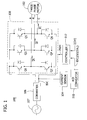
- Figure 1 is a diagram partially in block form and partially in schematic form of an apparatus according to one embodiment of the invention for supplying current to each phase of three-phase motor using a single current sensor.
- FIG. 2 is a timing diagram of the phase of PWM signals of a three phase motor according to one embodiment of the invention wherein motor phases A and B have a 42% duty cycle (e.g., operating during 150 degrees of a PWM cycle) and motor phase C has a 58% duty cycle (e.g., operating at 210 degrees of a PWM cycle).
- motor phases A and B have a 42% duty cycle (e.g., operating during 150 degrees of a PWM cycle) and motor phase C has a 58% duty cycle (e.g., operating at 210 degrees of a PWM cycle).
- 42% duty cycle e.g., operating during 150 degrees of a PWM cycle
- motor phase C has a 58% duty cycle (e.g., operating at 210 degrees of a PWM cycle).
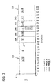
- FIG. 3 is a timing diagram of the phase of PWM signals of a three phase motor according to one embodiment of the invention wherein motor phases A and B have a 92% duty cycle (e.g., operating during 330 degrees of a PWM cycle) and motor phase C has a 8% duty cycle (e.g., operating at 30 degrees of a PWM cycle).
- motor phases A and B have a 92% duty cycle (e.g., operating during 330 degrees of a PWM cycle) and motor phase C has a 8% duty cycle (e.g., operating at 30 degrees of a PWM cycle).
- These duty cycles are simply examples for illustrative purposes.
- FIG. 1 is a diagram partially in block form and partially in schematic form showing an apparatus 100 for supplying current to each phase of multiphase alternating current motor such as a three phase motor 102 using a single current sensor 104.
- the apparatus 100 includes a converter 106 for converting alternating current from a three-phase AC (Alternating Current) power source 107 into direct current used to power a three phase motor 102.
- An inverter 108 comprises a switching array including a pair of switching devices Q1 and Q2, a pair of switching devices Q3 and Q4, and a pair of switching devices Q5 and Q6 for supplying power to the respective phases.
- either the upper or lower switch for a given phase is always on, except for brief periods during switching.
- the inverter 108 converts direct current from the converter 106 into alternating current and provides the alternating current to the three-phase motor 102.
- a current sensor 104 such as a shunt or other current sensing device or circuit measures current that flows through a bus line from the converter 106 or source 107 to the inverter 108.
- An analog-to digital (A/D) converter 110 periodically samples and converts an analog direct current value measured by the current sensor 104 into a digital current signal IDC (DIGITAL).
- a controller 112 generates a pulse width modulated (PWM) signal on the basis of the digital current signal from the A/D converter 110, to thus control switching of the switching devices Q 1 and Q2, the switching devices Q3 and Q4, and the switching devices Q5 and Q6 in the respective phases.
- PWM pulse width modulated
- the PWM signals for each of the three phases are offset a preset amount from each other. This allows periods of time that each phase can be sampled by a single current sensor. Whether a phase is HIGH or LOW depends on convention and definition. In one view, a particular phase is considered to be "HIGH” (or “on”) when a HIGH PWM pulse is applied to the switch between the particular phase and the positive DC line so that the switch is closed and conducting. A particular phase is considered to be "LOW” (or “off”) when a LOW PWM pulse is applied to the switch between the particular phase and the positive DC line so that the switch is an open circuit.
- the three currents IA, IB and IC can be measured or derived from the single current sensor 104. Without an offset, all PWM pulses could start and be "HIGH” (or “on”) at the same time, could start and be "LOW” (or “off”) at the same time, or could be too close to one another, so that sampling current from the current sensor would not indicate the current in a particular phase. Offsetting the starting times of the PWM streams results in predictable, known periods of time when the current flowing through the single current sensor 104 is the current in a particular motor phase or phases. Over a PWM cycle this occurs at a different time for each of the motor phases.
- sampling may occur at the center of the PWM pulses. In one embodiment, sampling may occur as a time which is a function of the leading edge, the trailing edge or the center of the PWM pulses. In one embodiment, the sampling is programmed to occur at times when no switching is occurring in any of the motor phases. Since the amplitude applied to each winding in response to the PWM pulse may vary sinusoidally with time (and be 120° offset), even during 100% duty cycles for a phase, there are known periods of time when the switches of other motor phases are such that individual phase currents can be sampled.
- the apparatus 100 uses the single current sensor 104 according to one embodiment of the invention to monitor the current in each phase of the motor 102.
- the converter 106 receives the three-phase alternating current from the three-phase current power source 107 and outputs to the inverter 108 direct current after rectifying and smoothing.
- the inverter 108 converts the direct current into alternating current and outputs the alternating current to the three-phase motor 102.
- the value of the direct current that flows between the converter 106 and the inverter 108 (e.g., flows through a direct current link) is measured using the current sensor 104.
- the measured analog direct current value is sampled and converted to digital data using the A/D converter 110 which provides a corresponding digital current signal that is output to the controller 112.
- the PWM signal is a rectangular wave for turning on or turning off the switch devices Q1-Q6 of the inverter to commutate each corresponding phase.
- the switching devices Q1-Q6 of the inverter 108 are turned on or closed when the pulse width modulated (PWM) square wave signal is at a high level and are turned off or opened when the PWM square wave signal is at a low level.
- PWM pulse width modulated
- the current sensor 104 is a shunt which measures the current IDC and outputs the measured value as an analog signal to the A/D converter 110.
- the controller 112 determines the values of the currents IA, IB, and IC of the respective phases on the basis of the digital current signal from the A/D converter 110 and on the basis that the PWM signals for each of the three phases are offset a preset amount from each other.
- the converter 110 is illustrated as a separate component from the controller 112, it is contemplated that the controller 112 may have an integral converter
- an offset of approximately 120° between each of the three phases may be implemented by the controller 112.
- the magnitude of the offset may be a function of or synchronized with the 120° offset frequently employed between the phases of the motor windings or synchronized with the frequency of the PWM signals.
- Figure 2 is a timing diagram of the phase of PWM signals of a three phase motor according to one embodiment of the invention wherein motor phases A and B have, for example, a 42% duty cycle (e.g., operating during 150 degrees of a PWM cycle) and motor phase C has a 58% duty cycle (e.g., operating at 210 degrees of a PWM cycle).
- phases A and B are HIGH (e.g., shown in the box) and C is LOW so that the controller would receive the digital current signal from the A/D converter 110 to measure the total current in phase C.
- the single phase that has a status (either HIGH or LOW) different from the other two phases is the phase that is measured.
- a and B are HIGH so C is the single phase having a status (LOW) which is different form the other two phases (A and B are HIGH) so that the current in C is measured.
- the controller may signal the A/D converter 110 to sample the analog current signal from current sensor 104.
- phase or phases in the box indicate the phase or phases which are HIGH.
- phase B is HIGH (e.g., shown in the box) and phases A and C are LOW so that the current sensor 104 and A/D converter 110 would indicate a measurement of the total current in phase B.
- A is LOW and measured since B and C have the same HIGH status
- a and B are LOW so that C has a singular HIGH status and is measured
- time period 210 B is LOW and measured since A and C have the same HIGH status and during time period 212 B and C are LOW and A has a singular high status and is measured.
- Figure 3 is a timing diagram of the phase of PWM signals of a three phase motor according to one embodiment of the invention wherein motor phases A and B have a 92% duty cycle (e.g., operating during 330 degrees of a PWM cycle) and motor phase C has a 8% duty cycle (e.g., operating at 30 degrees of a PWM cycle).
- motor phases A and B have a 92% duty cycle (e.g., operating during 330 degrees of a PWM cycle) and motor phase C has a 8% duty cycle (e.g., operating at 30 degrees of a PWM cycle).
- phases A and B are HIGH so that phase C is LOW and measured
- time period 304 A and C are LOW so that B is HIGH and measured
- time period 306 A and B are HIGH so that C is LOW and measured
- time period 308 all phases A, B and C are HIGH so no measurements are taken (or the measurement would indicate total current in all three phases)
- time period 310 A and B are HIGH so that C is LOW and measured and during time period 312 B and C are LOW so that A is HIGH and measured.
- the controller may not be able to determine the current for a particular phase because the particular phase is never HIGH (or LOW) by itself and thus cannot be sampled.
- the current in the particular phase can be reconstructed. For example, for an n-phase motor the controller would measure current during a period when all of the n-1 phases other than the particular phase are HIGH. By knowing that the total current is zero and by knowing the current in n-1 phases, the controller reconstructs the current for the particular phase as a function of the determined current in the n-1 phases and as a function of the total current. For example, for a three phase motor it would measure current during a period when the two phases are HIGH (or LOW).
- the controller reconstructs the current for the third phase as a function of the determined current in the two phases and as a function of the total current.
- Figure 3 does not require reconstruction. Reconstruction is only needed when one phase cannot be sampled.
- each phase can be sampled individually and separately. Above 240 degree, pairs of phase currents can be sampled to provide the following information which can be solved to reconstruct the individual currents IA, IB and IC:
- An offset of 120° according to one embodiment of the invention as noted above in a three phase motor is a preset amount which need not vary with the duty cycle of the PWM signals.
- the offset may be applied over the full range of possible duty cycles of PWM signals.
- using a preset offset can allow sensing of current during up to 100% of the PWM cycles.
- many prior art sensing methods are restricted to less than 100% to allow time for the A/D converter 110 to sample the analog current sensor output.
- embodiments of the invention offset the timing of the three phase PWM signals so that the current in each of the three phases of the motor 102 can be determined from the single current sensor 104.
- This reduces the cost of the drive and its physical size compared to some embodiments because it employs one current sensor instead of three current sensors and because of reduced requirements for the A/D converter 110 and the input amplifier.
- it allows for multiple current readings per phase per PWM cycle.
- offsetting the PWM signals by 120 degrees or some other offset according to embodiments of the invention may reduce audible noise generated.
- prior art motor drives which sensed current in each phase have higher costs.
- Prior art single sensor methods may also require more processing power to calculate variations in offsets with changing PWM duty cycles.
- the A/D converter 110 may be programmed to sample the analog signal from sensor 104 at fixed points with respect to the PWM signals and/or the controller 112 may be programmed to only receive and process digital current signals from the A/D converter 110 at fixed points with respect to the PWM signals.
- the fixed point may be a time (degrees) in the PWM cycle or a relative fixed point such as the leading or trailing edge or center of the PWM pulse, or at a minimum or maximum of the PWM signals.
- an apparatus 100 supplies current from a power source (e.g., ac source 107 and converter 106) to each phase A, B, C of a three-phase motor 102.
- a switching array or other inverter 108 interconnects the power source and each phase of the three-phase motor 102.
- a current sensor 104 senses current supplied from the power source via the switching array to the motor and a controller 112 responsive to the sensor 104 generates pulse width modulated (PWM) signals for controlling the switching array to supply power to each of the phases of the motor.
- PWM pulse width modulated
- the phase of the PWM signals (e.g., the leading edge, the trail edge or the center of each pulse) supplied by the controller 112 to the switching array to supply power to one of the phases is offset a preset amount from the PWM signals supplied by the controller to the switching array to supply power to at least one of the other phases.
- the offset between each of the three phases is approximately 120 degrees.
- the current sensor comprises a single current sensor for sensing current supplied to a bus which supplies power to the switching array (e.g., the motor drive).
- one embodiment of the invention comprises an apparatus 100 for supplying current from a power source 107 to first, second and third phases A, B, C of a motor 102.
- a first switching array Q1 and Q2 interconnects the power source 107 and the first phase A of the motor 102.
- a second switching array Q3 and Q4 interconnects the power source 107 and the second phase B of the motor 102.
- a third switching array Q5 and Q6 interconnects the power source 107 and the third phase C of the motor 102.
- a current sensor 104 senses current supplied by the power source 107 to the switching arrays.
- a controller 112 generates first PWM signals for controlling the first switching array to supply power to the first phase A of the motor 102, generates second PWM signals for controlling the second switching array to supply power to the second phase B of the motor 102, and generates third PWM signals for controlling the third switching array to supply power to the third phase C of the motor 102.
- the phase of the first PWM signals supplied by the controller 112 are offset a preset amount from at least one of the phases of the second and third PWM signals.
- One embodiment of the invention comprises a motor 102 including a switching array 108 for interconnecting a power source 107 to each phase A, B, C of a three-phase winding.
- a current sensor 104 senses current supplied from the power source 107 via the switching array 108 to the winding A, B, C.
- a controller 112 generates PWM signals for controlling the switching array 108 to supply power to each of the phases A, B, C of the winding, wherein the PWM signals supplied by the controller 112 to the switching array 108 to supply power to one of the phases is offset a preset amount from the PWM signals supplied by the controller 112 to the switching array to supply power to at least one of the other phases.
Landscapes
- Engineering & Computer Science (AREA)
- Power Engineering (AREA)
- Control Of Ac Motors In General (AREA)
- Control Of Motors That Do Not Use Commutators (AREA)
- Inverter Devices (AREA)
Abstract
Description
- The present invention generally relates to current sensing in multiphase motors and, in particular, using a single current sensor for sensing current in each phase of a multiphase motor drive.
- Three current sensors are normally needed to measure the currents in each phase of a three phase motor. Many control methods and systems for commutating the switches which selectively supply power to each of the three phases of a motor require three signals, one from each of the three current sensors in each phase, for operation. Some control methods and systems employ the signal from a current sensor connected to a bus supplying current to the three phases. The cost of the sensors and the related conditioning circuitry associated with each sensor adds cost to the motor drive. The sensors also take up additional space thereby making the overall size of the drive circuitry of the motor larger.
- Single current sensors are used in six step drives for three phase motors when individual phase current information is not needed. If individual phase current information is needed, more complex control methods and systems are employed.
- As another example,
U.S. Patent No. 6,642,690 discloses modifying PWM signals in one cycle to allow for measurement of the current in a particular phase. After measurement, the PWM signals are again modified to correct for any distortion caused by the first modification during which the current was measured. As another example,U.S. Patent No. 6,735,537 suggests a procedure for measuring the current in each phase of a three phase motor via a single sensor by shifting the drive signals applied to windings for individual phases only for specific cases of signal overlap to allow separating individual phase currents. As another example,U.S. Patent No. 6,914,409 relates to a current detection method which varies the offset of phase drive signals to allow separating each phase current from the combined current signal. The offset varies depending on the particular duty cycle of the PWM phase signals. In summary, such current sensing tends to dynamically shift the drive signals in real time. - According to one aspect of this invention, there is provided an apparatus for supplying current from a power source to each phase of a multi-phase motor. One or more switching arrays interconnect the power source and each phase of the multi-phase motor. One or more current sensors sense current supplied from the power source via the switching array to the motor. A controller generates pulse width modulated (PWM) signals for controlling the switching array(s) to supply power to each of the phases of the motor. The PWM signals supplied by the controller to the switching array(s) to supply power to each of the phases is offset a preset amount from the PWM signals supplied by the controller to the switching array to supply power to the other phases.
- In one embodiment, the offset timing allows the individual phase currents to be determined from a single current sensor.
- Other objects and features will be in part apparent and in part pointed out hereinafter.
- Figure 1 is a diagram partially in block form and partially in schematic form of an apparatus according to one embodiment of the invention for supplying current to each phase of three-phase motor using a single current sensor.
- Figure 2 is a timing diagram of the phase of PWM signals of a three phase motor according to one embodiment of the invention wherein motor phases A and B have a 42% duty cycle (e.g., operating during 150 degrees of a PWM cycle) and motor phase C has a 58% duty cycle (e.g., operating at 210 degrees of a PWM cycle). These duty cycles are simply examples for illustrative purposes.
- Figure 3 is a timing diagram of the phase of PWM signals of a three phase motor according to one embodiment of the invention wherein motor phases A and B have a 92% duty cycle (e.g., operating during 330 degrees of a PWM cycle) and motor phase C has a 8% duty cycle (e.g., operating at 30 degrees of a PWM cycle). These duty cycles are simply examples for illustrative purposes.
- Corresponding reference characters indicate corresponding parts throughout the drawings.
- One embodiment of the present invention is illustrated in FIG. 1, which is a diagram partially in block form and partially in schematic form showing an
apparatus 100 for supplying current to each phase of multiphase alternating current motor such as a threephase motor 102 using a singlecurrent sensor 104. Theapparatus 100 includes aconverter 106 for converting alternating current from a three-phase AC (Alternating Current)power source 107 into direct current used to power a threephase motor 102. Aninverter 108 comprises a switching array including a pair of switching devices Q1 and Q2, a pair of switching devices Q3 and Q4, and a pair of switching devices Q5 and Q6 for supplying power to the respective phases. Generally, either the upper or lower switch for a given phase is always on, except for brief periods during switching. Theinverter 108 converts direct current from theconverter 106 into alternating current and provides the alternating current to the three-phase motor 102. Acurrent sensor 104 such as a shunt or other current sensing device or circuit measures current that flows through a bus line from theconverter 106 orsource 107 to theinverter 108. An analog-to digital (A/D)converter 110 periodically samples and converts an analog direct current value measured by thecurrent sensor 104 into a digital current signal IDC (DIGITAL). Acontroller 112 generates a pulse width modulated (PWM) signal on the basis of the digital current signal from the A/D converter 110, to thus control switching of theswitching devices Q 1 and Q2, the switching devices Q3 and Q4, and the switching devices Q5 and Q6 in the respective phases. - The PWM signals for each of the three phases are offset a preset amount from each other. This allows periods of time that each phase can be sampled by a single current sensor. Whether a phase is HIGH or LOW depends on convention and definition. In one view, a particular phase is considered to be "HIGH" (or "on") when a HIGH PWM pulse is applied to the switch between the particular phase and the positive DC line so that the switch is closed and conducting. A particular phase is considered to be "LOW" (or "off") when a LOW PWM pulse is applied to the switch between the particular phase and the positive DC line so that the switch is an open circuit.
- By offsetting the PWM signals in the three phases of the
motor 102, the three currents IA, IB and IC can be measured or derived from the singlecurrent sensor 104. Without an offset, all PWM pulses could start and be "HIGH" (or "on") at the same time, could start and be "LOW" (or "off") at the same time, or could be too close to one another, so that sampling current from the current sensor would not indicate the current in a particular phase. Offsetting the starting times of the PWM streams results in predictable, known periods of time when the current flowing through the singlecurrent sensor 104 is the current in a particular motor phase or phases. Over a PWM cycle this occurs at a different time for each of the motor phases. - In one embodiment, sampling may occur at the center of the PWM pulses. In one embodiment, sampling may occur as a time which is a function of the leading edge, the trailing edge or the center of the PWM pulses. In one embodiment, the sampling is programmed to occur at times when no switching is occurring in any of the motor phases. Since the amplitude applied to each winding in response to the PWM pulse may vary sinusoidally with time (and be 120° offset), even during 100% duty cycles for a phase, there are known periods of time when the switches of other motor phases are such that individual phase currents can be sampled.
- In operation, the
apparatus 100 uses the singlecurrent sensor 104 according to one embodiment of the invention to monitor the current in each phase of themotor 102. However, it is contemplated that more than one current sensor may be used. Theconverter 106 receives the three-phase alternating current from the three-phasecurrent power source 107 and outputs to theinverter 108 direct current after rectifying and smoothing. Theinverter 108 converts the direct current into alternating current and outputs the alternating current to the three-phase motor 102. The value of the direct current that flows between theconverter 106 and the inverter 108 (e.g., flows through a direct current link) is measured using thecurrent sensor 104. The measured analog direct current value is sampled and converted to digital data using the A/D converter 110 which provides a corresponding digital current signal that is output to thecontroller 112. - In one embodiment, the PWM signal is a rectangular wave for turning on or turning off the switch devices Q1-Q6 of the inverter to commutate each corresponding phase. The switching devices Q1-Q6 of the
inverter 108 are turned on or closed when the pulse width modulated (PWM) square wave signal is at a high level and are turned off or opened when the PWM square wave signal is at a low level. - In one embodiment, the
current sensor 104 is a shunt which measures the current IDC and outputs the measured value as an analog signal to the A/D converter 110. Thecontroller 112 determines the values of the currents IA, IB, and IC of the respective phases on the basis of the digital current signal from the A/D converter 110 and on the basis that the PWM signals for each of the three phases are offset a preset amount from each other. Although theconverter 110 is illustrated as a separate component from thecontroller 112, it is contemplated that thecontroller 112 may have an integral converter - For example, in one embodiment as illustrated in Figures 2 and 3, an offset of approximately 120° between each of the three phases may be implemented by the
controller 112. The magnitude of the offset may be a function of or synchronized with the 120° offset frequently employed between the phases of the motor windings or synchronized with the frequency of the PWM signals. Figure 2 is a timing diagram of the phase of PWM signals of a three phase motor according to one embodiment of the invention wherein motor phases A and B have, for example, a 42% duty cycle (e.g., operating during 150 degrees of a PWM cycle) and motor phase C has a 58% duty cycle (e.g., operating at 210 degrees of a PWM cycle). Duringtime period 202, phases A and B are HIGH (e.g., shown in the box) and C is LOW so that the controller would receive the digital current signal from the A/D converter 110 to measure the total current in phase C. In a three phase motor, the single phase that has a status (either HIGH or LOW) different from the other two phases is the phase that is measured. For example, duringtime period 202, A and B are HIGH so C is the single phase having a status (LOW) which is different form the other two phases (A and B are HIGH) so that the current in C is measured. Alternatively, or in addition, the controller may signal the A/D converter 110 to sample the analog current signal fromcurrent sensor 104. - In FIGS. 2 and 3, the phase or phases in the box indicate the phase or phases which are HIGH. During
time period 204, phase B is HIGH (e.g., shown in the box) and phases A and C are LOW so that thecurrent sensor 104 and A/D converter 110 would indicate a measurement of the total current in phase B. Similarly, duringtime period 206, A is LOW and measured since B and C have the same HIGH status, during time period 208 A and B are LOW so that C has a singular HIGH status and is measured, during time period 210 B is LOW and measured since A and C have the same HIGH status and during time period 212 B and C are LOW and A has a singular high status and is measured. - Figure 3 is a timing diagram of the phase of PWM signals of a three phase motor according to one embodiment of the invention wherein motor phases A and B have a 92% duty cycle (e.g., operating during 330 degrees of a PWM cycle) and motor phase C has a 8% duty cycle (e.g., operating at 30 degrees of a PWM cycle). During
time period 302, phases A and B are HIGH so that phase C is LOW and measured, during time period 304 A and C are LOW so that B is HIGH and measured, during time period 306 A and B are HIGH so that C is LOW and measured, duringtime period 308 all phases A, B and C are HIGH so no measurements are taken (or the measurement would indicate total current in all three phases), during time period 310 A and B are HIGH so that C is LOW and measured and during time period 312 B and C are LOW so that A is HIGH and measured. - In certain cases of an n-phase motor, the controller may not be able to determine the current for a particular phase because the particular phase is never HIGH (or LOW) by itself and thus cannot be sampled. However, by measuring the current in the other n-1 phases, the current in the particular phase can be reconstructed. For example, for an n-phase motor the controller would measure current during a period when all of the n-1 phases other than the particular phase are HIGH. By knowing that the total current is zero and by knowing the current in n-1 phases, the controller reconstructs the current for the particular phase as a function of the determined current in the n-1 phases and as a function of the total current. For example, for a three phase motor it would measure current during a period when the two phases are HIGH (or LOW). By knowing that the total current is zero and by knowing the current in two of the phases, the controller reconstructs the current for the third phase as a function of the determined current in the two phases and as a function of the total current. Figure 3 does not require reconstruction. Reconstruction is only needed when one phase cannot be sampled.
- In one embodiment, depending on waveform configurations and commutation scenarios, for PWM duty cycles in which the pulses are less than 240 degrees, each phase can be sampled individually and separately. Above 240 degree, pairs of phase currents can be sampled to provide the following information which can be solved to reconstruct the individual currents IA, IB and IC:
- IA + IB =
Sample 1; - IB + IC = Sample 2; and
- IC + IA = Sample 3.
- An offset of 120° according to one embodiment of the invention as noted above in a three phase motor is a preset amount which need not vary with the duty cycle of the PWM signals. In addition, the offset may be applied over the full range of possible duty cycles of PWM signals. Further, using a preset offset can allow sensing of current during up to 100% of the PWM cycles. In contrast, many prior art sensing methods are restricted to less than 100% to allow time for the A/
D converter 110 to sample the analog current sensor output. - As a result, embodiments of the invention offset the timing of the three phase PWM signals so that the current in each of the three phases of the
motor 102 can be determined from the singlecurrent sensor 104. This reduces the cost of the drive and its physical size compared to some embodiments because it employs one current sensor instead of three current sensors and because of reduced requirements for the A/D converter 110 and the input amplifier. Furthermore, it allows for multiple current readings per phase per PWM cycle. In addition, in certain motors and certain commutation schemes, offsetting the PWM signals by 120 degrees or some other offset according to embodiments of the invention may reduce audible noise generated. In contrast, prior art motor drives which sensed current in each phase have higher costs. Prior art single sensor methods may also require more processing power to calculate variations in offsets with changing PWM duty cycles. - As an alternative, the A/
D converter 110 may be programmed to sample the analog signal fromsensor 104 at fixed points with respect to the PWM signals and/or thecontroller 112 may be programmed to only receive and process digital current signals from the A/D converter 110 at fixed points with respect to the PWM signals. As some examples, the fixed point may be a time (degrees) in the PWM cycle or a relative fixed point such as the leading or trailing edge or center of the PWM pulse, or at a minimum or maximum of the PWM signals. - Thus, in summary, in one embodiment, an
apparatus 100 supplies current from a power source (e.g.,ac source 107 and converter 106) to each phase A, B, C of a three-phase motor 102. A switching array orother inverter 108 interconnects the power source and each phase of the three-phase motor 102. Acurrent sensor 104 senses current supplied from the power source via the switching array to the motor and acontroller 112 responsive to thesensor 104 generates pulse width modulated (PWM) signals for controlling the switching array to supply power to each of the phases of the motor. The phase of the PWM signals (e.g., the leading edge, the trail edge or the center of each pulse) supplied by thecontroller 112 to the switching array to supply power to one of the phases is offset a preset amount from the PWM signals supplied by the controller to the switching array to supply power to at least one of the other phases. In one embodiment, the offset between each of the three phases is approximately 120 degrees. In one embodiment, the current sensor comprises a single current sensor for sensing current supplied to a bus which supplies power to the switching array (e.g., the motor drive). - In summary, one embodiment of the invention comprises an
apparatus 100 for supplying current from apower source 107 to first, second and third phases A, B, C of amotor 102. A first switching array Q1 and Q2 interconnects thepower source 107 and the first phase A of themotor 102. A second switching array Q3 and Q4 interconnects thepower source 107 and the second phase B of themotor 102. A third switching array Q5 and Q6 interconnects thepower source 107 and the third phase C of themotor 102. Acurrent sensor 104 senses current supplied by thepower source 107 to the switching arrays. Acontroller 112 generates first PWM signals for controlling the first switching array to supply power to the first phase A of themotor 102, generates second PWM signals for controlling the second switching array to supply power to the second phase B of themotor 102, and generates third PWM signals for controlling the third switching array to supply power to the third phase C of themotor 102. The phase of the first PWM signals supplied by thecontroller 112 are offset a preset amount from at least one of the phases of the second and third PWM signals. - One embodiment of the invention comprises a
motor 102 including aswitching array 108 for interconnecting apower source 107 to each phase A, B, C of a three-phase winding. Acurrent sensor 104 senses current supplied from thepower source 107 via theswitching array 108 to the winding A, B, C. Acontroller 112 generates PWM signals for controlling theswitching array 108 to supply power to each of the phases A, B, C of the winding, wherein the PWM signals supplied by thecontroller 112 to theswitching array 108 to supply power to one of the phases is offset a preset amount from the PWM signals supplied by thecontroller 112 to the switching array to supply power to at least one of the other phases. - Having described embodiments of the invention in detail, it will be apparent that modifications and variations are possible without departing from the scope of the invention defined in the appended claims.
- When introducing elements of the present invention or the preferred embodiments(s) thereof, the articles "a", "an", "the" and "said" are intended to mean that there are one or more of the elements. The terms "comprising", "including" and "having" are intended to be inclusive and mean that there may be additional elements other than the listed elements.
- In view of the above, it will be seen that the several objects of the invention are achieved and other advantageous results attained.
- As various changes could be made in the above constructions, products, and methods without departing from the scope of the invention, it is intended that all matter contained in the above description and shown in the accompanying drawings shall be interpreted as illustrative and not in a limiting sense.
Claims (8)
- An apparatus for supplying current from a power source to each phase of a multi-phase motor comprising:a switching array interconnecting the power source and each phase of the multi-phase motor;a current sensor for sensing current supplied from the power source via the switching array to the motor; anda controller for generating pulse width modulated (PWM) signals for controlling the switching array to supply power to each of the phases of the motor, wherein the PWM signals supplied by the controller to the switching array to supply power to each of the phases is offset a preset amount from the PWM signals supplied by the controller to the switching array to supply power to the other phases.
- The apparatus of claim 1 wherein the motor is a three phase motor and wherein the offset between each of the three phases is approximately 120 degrees.
- The apparatus of claim 1 or 2 wherein the current sensor comprises a single current sensor for sensing current supplied to the switching array.
- The apparatus of claims 1-3 further comprising an A/D converter converting an analog signal from the current sensor into a digital signal supplied to the controller, said A/D converter sampling the analog signal at a sampling rate which is in synchronization with a frequency of the PWM signals.
- The apparatus of claims 1-4 further comprising an A/D converter converting an analog signal from the current sensor into a digital signal supplied to the controller, said A/D converter sampling the analog signal at a sampling rate which is independent of a frequency of the PWM signals.
- The apparatus of claims 1-5 further comprising an A/D converter converting an analog signal from the current sensor into a digital signal supplied to the controller, said A/D converter sampling the analog signal at fixed points with respect to the PWM signals, wherein said A/D converter samples the analog signals at or as a function of a leading edge, a trailing edge or a center of each of the PWM signals.
- The apparatus of claims 1-6 for supplying current from a power source to first, second and third phases of a motor further comprising:A first switching array interconnecting the power source and the first phase of the motor;A second switching array interconnecting the power source and the second phase of the motor;A third switching array interconnecting the power source and the third phase of the motor;a current sensor for sensing current supplied by the power source to the switching arrays; andwherein the controller generates first PWM signals for controlling the first switching array to supply power to the first phase of the motor, generates second PWM signals for controlling the second switching array to supply power to the second phase of the motor, and generates third PWM signals for controlling the third switching array to supply power to the third phase of the motor, wherein each of the PWM signals supplied by the controller to each switching array are offset a preset amount from the PWM signals supplied by the controller to other switching arrays.
- The apparatus of claims 1-7 in combination with a motor having a multi-phase winding wherein the switching array interconnects a power source to each phase of the multi-phase winding; wherein the current sensor senses current supplied from the power source via the switching array to the winding; and wherein the controller generates PWM signals for controlling the switching array to supply power to each of the phases of the winding, wherein the PWM signals supplied by the controller to the switching array to supply power to each of the phases is offset a preset amount from the PWM signals supplied by the controller to the switching array to supply power to the other phases.
Applications Claiming Priority (1)
| Application Number | Priority Date | Filing Date | Title |
|---|---|---|---|
| US11/346,027 US7193388B1 (en) | 2006-02-02 | 2006-02-02 | Offset PWM signals for multiphase motor |
Publications (3)
| Publication Number | Publication Date |
|---|---|
| EP1816738A2 true EP1816738A2 (en) | 2007-08-08 |
| EP1816738A3 EP1816738A3 (en) | 2009-09-02 |
| EP1816738B1 EP1816738B1 (en) | 2015-07-15 |
Family
ID=37863838
Family Applications (1)
| Application Number | Title | Priority Date | Filing Date |
|---|---|---|---|
| EP07250433.5A Not-in-force EP1816738B1 (en) | 2006-02-02 | 2007-02-01 | Offset PWM signals for multiphase motor |
Country Status (4)
| Country | Link |
|---|---|
| US (1) | US7193388B1 (en) |
| EP (1) | EP1816738B1 (en) |
| KR (1) | KR101192520B1 (en) |
| CN (1) | CN100553112C (en) |
Families Citing this family (38)
| Publication number | Priority date | Publication date | Assignee | Title |
|---|---|---|---|---|
| US8072180B1 (en) * | 2002-12-03 | 2011-12-06 | Deka Products Limited Partnership | Synchronous sampling of PWM waveforms |
| US7109742B2 (en) * | 2004-07-12 | 2006-09-19 | Motorola, Inc. | Current sensing in a two-phase motor |
| JP5168448B2 (en) * | 2007-02-26 | 2013-03-21 | 株式会社ジェイテクト | Motor control device and electric power steering device |
| JP2008211909A (en) * | 2007-02-26 | 2008-09-11 | Jtekt Corp | Motor control device and electric power steering device |
| JP2008211910A (en) * | 2007-02-26 | 2008-09-11 | Jtekt Corp | Motor control device and electric power steering device |
| JP5056175B2 (en) * | 2007-06-01 | 2012-10-24 | 株式会社ジェイテクト | Motor control device and electric power steering device |
| JP5233178B2 (en) * | 2007-06-14 | 2013-07-10 | 株式会社ジェイテクト | Motor control device and electric power steering device |
| JP5082719B2 (en) * | 2007-09-26 | 2012-11-28 | 株式会社ジェイテクト | Motor control device and electric power steering device |
| JP5252475B2 (en) * | 2007-11-06 | 2013-07-31 | オムロンオートモーティブエレクトロニクス株式会社 | Control device for multiphase motor |
| US7834574B2 (en) * | 2007-11-26 | 2010-11-16 | Gm Global Technology Operations, Inc. | Phase current sampling and regulating apparatus and methods, and electric motor drive systems |
| JP4884356B2 (en) * | 2007-11-26 | 2012-02-29 | オムロンオートモーティブエレクトロニクス株式会社 | Control device for multiphase motor |
| JP4884355B2 (en) * | 2007-11-26 | 2012-02-29 | オムロンオートモーティブエレクトロニクス株式会社 | Control device for multiphase motor |
| BRPI0803139A2 (en) * | 2008-08-05 | 2010-08-03 | Washington Corsi Pereira | electro-electronic device |
| US8050543B2 (en) * | 2008-09-14 | 2011-11-01 | Honeywell International Inc. | Trigger mechanism for current acquisition used for motor control applications |
| KR101517101B1 (en) * | 2008-10-02 | 2015-05-04 | 삼성전자 주식회사 | Method for predicting phase current |
| US8878482B2 (en) * | 2009-06-08 | 2014-11-04 | Mitsubishi Electric Corporation | Power converting apparatus |
| WO2011003220A1 (en) * | 2009-07-09 | 2011-01-13 | Texas Instruments Incorporated | Inverter current measurement using shunt resistor |
| US8698433B2 (en) | 2009-08-10 | 2014-04-15 | Emerson Climate Technologies, Inc. | Controller and method for minimizing phase advance current |
| US8344706B2 (en) * | 2009-08-10 | 2013-01-01 | Emerson Climate Technologies, Inc. | System and method for rejecting DC current in power factor correction systems |
| US8508166B2 (en) | 2009-08-10 | 2013-08-13 | Emerson Climate Technologies, Inc. | Power factor correction with variable bus voltage |
| US8358098B2 (en) * | 2009-08-10 | 2013-01-22 | Emerson Climate Technologies, Inc. | System and method for power factor correction |
| US8476873B2 (en) * | 2009-08-10 | 2013-07-02 | Emerson Climate Technologies, Inc. | System and method for current balancing |
| US8264192B2 (en) | 2009-08-10 | 2012-09-11 | Emerson Climate Technologies, Inc. | Controller and method for transitioning between control angles |
| US8406021B2 (en) * | 2009-08-10 | 2013-03-26 | Emerson Climate Technologies, Inc. | System and method for reducing line current distortion |
| US8264860B2 (en) * | 2009-08-10 | 2012-09-11 | Emerson Climate Technologies, Inc. | System and method for power factor correction frequency tracking and reference generation |
| US8493014B2 (en) * | 2009-08-10 | 2013-07-23 | Emerson Climate Technologies, Inc. | Controller and method for estimating, managing, and diagnosing motor parameters |
| TWI441443B (en) * | 2010-10-18 | 2014-06-11 | Hon Hai Prec Ind Co Ltd | Control circuit for fan |
| CN102454621A (en) * | 2010-10-21 | 2012-05-16 | 鸿富锦精密工业(深圳)有限公司 | Fan control circuit |
| JP5402948B2 (en) * | 2011-01-05 | 2014-01-29 | 日本精工株式会社 | Motor control device and electric power steering device using the same |
| US9634593B2 (en) | 2012-04-26 | 2017-04-25 | Emerson Climate Technologies, Inc. | System and method for permanent magnet motor control |
| WO2014026124A1 (en) | 2012-08-10 | 2014-02-13 | Emerson Climate Technologies, Inc. | Motor drive control using pulse-width modulation pulse skipping |
| CN103280986A (en) * | 2013-06-09 | 2013-09-04 | 浙江海振电子科技有限公司 | Frequency converter with anti-toppling switch |
| CN103715975B (en) * | 2013-12-31 | 2016-04-20 | 清华大学 | The device that a kind of control plane motor coil electric current switches fast |
| US20150214871A1 (en) * | 2014-01-28 | 2015-07-30 | Moog Inc. | Method and System for Determining Motor Shaft Position |
| JP7067135B2 (en) * | 2018-03-07 | 2022-05-16 | 株式会社デンソー | Power converter |
| US10320323B1 (en) | 2018-03-28 | 2019-06-11 | Infineon Technologies Austria Ag | Pulse width modulation (PWM) scheme for single shunt motor control |
| CN115004496B (en) * | 2019-12-03 | 2026-04-10 | Lg伊诺特有限公司 | Device and method for measuring current in a three-phase inverter |
| US11761985B2 (en) * | 2021-02-09 | 2023-09-19 | Analog Devices International Unlimited Company | Calibration using flipped sensor for highly dynamic system |
Citations (2)
| Publication number | Priority date | Publication date | Assignee | Title |
|---|---|---|---|---|
| US6914409B2 (en) | 2001-03-26 | 2005-07-05 | Toshiba Carrier Corporation | Current detection method and control apparatus for electric motor |
| US20050174076A1 (en) | 2004-02-09 | 2005-08-11 | Nippon Yusoki Co., Ltd. | Inverter control apparatus and inverter control method |
Family Cites Families (34)
| Publication number | Priority date | Publication date | Assignee | Title |
|---|---|---|---|---|
| GB2190754A (en) * | 1986-04-11 | 1987-11-25 | Hitachi Ltd | Load current detecting device for pulse width modulation inverter |
| US5023537A (en) | 1989-08-23 | 1991-06-11 | Sundstrand Corporation | Low frequency feeder fault protection |
| US5245525A (en) | 1991-10-24 | 1993-09-14 | Sundstrand Corporation | DC current control through an interphase transformer using differential current sensing |
| US5337013A (en) | 1992-06-10 | 1994-08-09 | Ford Motor Company | Method and apparatus for monitoring the operation of electrical loads in an automotive vehicle |
| GB9509408D0 (en) | 1995-05-10 | 1995-07-05 | Switched Reluctance Drives Ltd | Sensing phase current in switched reluctance machines |
| IT1280973B1 (en) | 1995-10-17 | 1998-02-11 | Bitron Spa | METHOD AND CONTROL APPARATUS FOR THE PILOTING OF STATIC ELECTRONIC COMPONENTS SUITABLE TO PERFORM THE SWITCHING OF THE PHASES IN |
| US6104149A (en) | 1997-02-28 | 2000-08-15 | International Rectifier Corp. | Circuit and method for improving short-circuit capability of IGBTs |
| US5874818A (en) * | 1997-06-11 | 1999-02-23 | Agile Systems, Inc. | Method and apparatus for sensing load current in a motor controller |
| US5977741A (en) | 1998-11-17 | 1999-11-02 | Allen-Bradley Company, Llc | Method for stabilizing AC induction motor having an open loop inverter |
| US6456946B1 (en) * | 2000-02-25 | 2002-09-24 | Motorola, Inc. | System and method for motor fault detection |
| JP4131079B2 (en) | 2000-07-12 | 2008-08-13 | 株式会社安川電機 | Inverter device and current limiting method thereof |
| WO2002050989A1 (en) | 2000-12-07 | 2002-06-27 | Kabushiki Kaisha Yaskawa Denki | Three-level neutral point clamping pwm inverter and neutral point voltage controller |
| JP2002315343A (en) * | 2001-04-18 | 2002-10-25 | Hitachi Ltd | PWM converter device |
| KR100425851B1 (en) | 2001-05-10 | 2004-04-03 | 엘지산전 주식회사 | Method for measuring three-phase current with single current sensor |
| US6798157B2 (en) | 2001-08-20 | 2004-09-28 | International Rectifier Corporation | Combined motor drive and current sensing circuit |
| US6801005B2 (en) | 2001-10-26 | 2004-10-05 | Load Logic, Inc. | Method and apparatus for controlling three-phase power |
| US6735537B2 (en) * | 2002-03-15 | 2004-05-11 | Motorola, Inc. | Procedure for measuring the current in each phase of a three-phase device via single current sensor |
| US20060071627A1 (en) | 2002-03-28 | 2006-04-06 | Ho Eddy Y Y | Motor current reconstruction via DC bus current measurement |
| US7202622B2 (en) | 2002-04-30 | 2007-04-10 | International Rectifier Corporation | Method for controlling an electric motor to reduce EMI |
| FI112558B (en) | 2002-05-17 | 2003-12-15 | Vacon Oyj | Inverter control |
| DE10247900A1 (en) | 2002-10-14 | 2004-04-22 | Robert Bosch Gmbh | Method and device for the power supply of an electronically commutable electric motor |
| US20040227476A1 (en) | 2002-12-19 | 2004-11-18 | International Rectifier Corp. | Flexible inverter power module for motor drives |
| US6984953B2 (en) * | 2003-01-20 | 2006-01-10 | International Rectifier Corporation | Method and apparatus for reconstructing motor current from DC bus current |
| JP2004282969A (en) * | 2003-03-19 | 2004-10-07 | Hitachi Ltd | Control device and control method for AC motor |
| KR100488529B1 (en) | 2003-05-20 | 2005-05-11 | 삼성전자주식회사 | apparatus and method for controlling inverter for driving 3phase-motor |
| JP2005269880A (en) * | 2003-06-19 | 2005-09-29 | Denso Corp | Three-phase voltage type PWM inverter device |
| JP4300903B2 (en) | 2003-06-23 | 2009-07-22 | 株式会社安川電機 | Method of detecting output current of three-phase PWM inverter and three-phase PWM inverter device using the same |
| US20050017760A1 (en) | 2003-07-22 | 2005-01-27 | International Rectifier Corporation | Current sense shunt resistor circuit |
| US7026772B2 (en) | 2004-01-14 | 2006-04-11 | International Rectifier Corporation | Position sensorless drive for permanent magnet synchronous motors |
| JP2005224070A (en) * | 2004-02-09 | 2005-08-18 | Nippon Yusoki Co Ltd | Inverter control device and method therefor |
| US7012393B2 (en) | 2004-03-30 | 2006-03-14 | International Rectifier Corporation | Motor drive |
| WO2006022142A1 (en) * | 2004-08-27 | 2006-03-02 | Mitsubishi Denki Kabushiki Kaisha | Three-phase pwm signal generator |
| JP4455981B2 (en) * | 2004-11-30 | 2010-04-21 | 株式会社日立産機システム | Synchronous motor drive device |
| US7119530B2 (en) * | 2005-02-04 | 2006-10-10 | Delphi Technologies, Inc. | Motor phase current measurement using a single DC bus shunt sensor |
-
2006
- 2006-02-02 US US11/346,027 patent/US7193388B1/en not_active Expired - Lifetime
-
2007
- 2007-02-01 KR KR1020070010538A patent/KR101192520B1/en not_active Expired - Fee Related
- 2007-02-01 EP EP07250433.5A patent/EP1816738B1/en not_active Not-in-force
- 2007-02-02 CN CNB2007100065383A patent/CN100553112C/en not_active Expired - Fee Related
Patent Citations (2)
| Publication number | Priority date | Publication date | Assignee | Title |
|---|---|---|---|---|
| US6914409B2 (en) | 2001-03-26 | 2005-07-05 | Toshiba Carrier Corporation | Current detection method and control apparatus for electric motor |
| US20050174076A1 (en) | 2004-02-09 | 2005-08-11 | Nippon Yusoki Co., Ltd. | Inverter control apparatus and inverter control method |
Also Published As
| Publication number | Publication date |
|---|---|
| EP1816738B1 (en) | 2015-07-15 |
| US7193388B1 (en) | 2007-03-20 |
| CN100553112C (en) | 2009-10-21 |
| CN101018037A (en) | 2007-08-15 |
| EP1816738A3 (en) | 2009-09-02 |
| KR101192520B1 (en) | 2012-10-17 |
| KR20070079577A (en) | 2007-08-07 |
Similar Documents
| Publication | Publication Date | Title |
|---|---|---|
| US7193388B1 (en) | Offset PWM signals for multiphase motor | |
| US6984953B2 (en) | Method and apparatus for reconstructing motor current from DC bus current | |
| KR101368707B1 (en) | Method and apparatus for current measurement in an in particular polyphase electrical system | |
| EP1944860B1 (en) | A method for sensorless estimation of rotor speed and position of a permanent magnet synchronous machine | |
| US7598698B2 (en) | Motor control device | |
| EP2037567B1 (en) | Improvements relating to driving brushless DC (BLDC) motors | |
| EP2180589A2 (en) | Method to predict phase current | |
| EP2254236A1 (en) | Inverter device | |
| US20040095090A1 (en) | Method of detecting motor current and motor control device | |
| EP2442437B1 (en) | Power converter | |
| JP2007259675A (en) | Power converter system | |
| KR940001915B1 (en) | Slip detection device and control device of compressor using same | |
| JP2007336641A (en) | Position sensorless drive device for synchronous motor | |
| EP1863160B1 (en) | Measurement of the current of a frequency converter | |
| JP4031965B2 (en) | Electric motor control device | |
| JP2006230169A (en) | Control device for synchronous machine | |
| EP1956380B1 (en) | Method and related device for estimating two currents flowing simultaneously through respective windings of a poly-phase electrical load driven in SVM mode | |
| US8456117B2 (en) | Driving brushless DC (BLDC) motors | |
| JP5466482B2 (en) | Digital conversion device and power conversion device | |
| JP4178946B2 (en) | Inverter device and motor current detection method | |
| JP2004208395A (en) | Current detector of inverter | |
| CN118688699A (en) | Method and device for monitoring phase current sensors | |
| Samuelsen et al. | PWM-synchronised flux position estimator for sensorless motor drive with IM based on FPGA | |
| KR100374830B1 (en) | Phase current detecting method of motor | |
| JP2009118568A (en) | Three-phase motor control device and control method |
Legal Events
| Date | Code | Title | Description |
|---|---|---|---|
| PUAI | Public reference made under article 153(3) epc to a published international application that has entered the european phase |
Free format text: ORIGINAL CODE: 0009012 |
|
| AK | Designated contracting states |
Kind code of ref document: A2 Designated state(s): AT BE BG CH CY CZ DE DK EE ES FI FR GB GR HU IE IS IT LI LT LU LV MC NL PL PT RO SE SI SK TR |
|
| AX | Request for extension of the european patent |
Extension state: AL BA HR MK YU |
|
| PUAL | Search report despatched |
Free format text: ORIGINAL CODE: 0009013 |
|
| AK | Designated contracting states |
Kind code of ref document: A3 Designated state(s): AT BE BG CH CY CZ DE DK EE ES FI FR GB GR HU IE IS IT LI LT LU LV MC NL PL PT RO SE SI SK TR |
|
| AX | Request for extension of the european patent |
Extension state: AL BA HR MK RS |
|
| RIC1 | Information provided on ipc code assigned before grant |
Ipc: H02M 7/5387 20070101ALI20090729BHEP Ipc: H02P 23/00 20060101AFI20070608BHEP |
|
| 17P | Request for examination filed |
Effective date: 20100104 |
|
| 17Q | First examination report despatched |
Effective date: 20100201 |
|
| AKX | Designation fees paid |
Designated state(s): AT BE BG CH CY CZ DE DK EE ES FI FR GB GR HU IE IS IT LI LT LU LV MC NL PL PT RO SE SI SK TR |
|
| REG | Reference to a national code |
Ref country code: DE Ref legal event code: R079 Ref document number: 602007042146 Country of ref document: DE Free format text: PREVIOUS MAIN CLASS: H02P0023000000 Ipc: H02M0007538700 |
|
| GRAP | Despatch of communication of intention to grant a patent |
Free format text: ORIGINAL CODE: EPIDOSNIGR1 |
|
| RIC1 | Information provided on ipc code assigned before grant |
Ipc: H02M 1/00 20070101ALI20150211BHEP Ipc: H02M 7/5387 20070101AFI20150211BHEP |
|
| INTG | Intention to grant announced |
Effective date: 20150225 |
|
| GRAS | Grant fee paid |
Free format text: ORIGINAL CODE: EPIDOSNIGR3 |
|
| GRAA | (expected) grant |
Free format text: ORIGINAL CODE: 0009210 |
|
| AK | Designated contracting states |
Kind code of ref document: B1 Designated state(s): AT BE BG CH CY CZ DE DK EE ES FI FR GB GR HU IE IS IT LI LT LU LV MC NL PL PT RO SE SI SK TR |
|
| REG | Reference to a national code |
Ref country code: GB Ref legal event code: FG4D Ref country code: CH Ref legal event code: EP |
|
| REG | Reference to a national code |
Ref country code: IE Ref legal event code: FG4D |
|
| REG | Reference to a national code |
Ref country code: AT Ref legal event code: REF Ref document number: 737230 Country of ref document: AT Kind code of ref document: T Effective date: 20150815 |
|
| REG | Reference to a national code |
Ref country code: DE Ref legal event code: R096 Ref document number: 602007042146 Country of ref document: DE |
|
| REG | Reference to a national code |
Ref country code: SE Ref legal event code: TRGR |
|
| REG | Reference to a national code |
Ref country code: AT Ref legal event code: MK05 Ref document number: 737230 Country of ref document: AT Kind code of ref document: T Effective date: 20150715 |
|
| REG | Reference to a national code |
Ref country code: NL Ref legal event code: MP Effective date: 20150715 |
|
| REG | Reference to a national code |
Ref country code: LT Ref legal event code: MG4D |
|
| PG25 | Lapsed in a contracting state [announced via postgrant information from national office to epo] |
Ref country code: LV Free format text: LAPSE BECAUSE OF FAILURE TO SUBMIT A TRANSLATION OF THE DESCRIPTION OR TO PAY THE FEE WITHIN THE PRESCRIBED TIME-LIMIT Effective date: 20150715 Ref country code: LT Free format text: LAPSE BECAUSE OF FAILURE TO SUBMIT A TRANSLATION OF THE DESCRIPTION OR TO PAY THE FEE WITHIN THE PRESCRIBED TIME-LIMIT Effective date: 20150715 Ref country code: FI Free format text: LAPSE BECAUSE OF FAILURE TO SUBMIT A TRANSLATION OF THE DESCRIPTION OR TO PAY THE FEE WITHIN THE PRESCRIBED TIME-LIMIT Effective date: 20150715 Ref country code: GR Free format text: LAPSE BECAUSE OF FAILURE TO SUBMIT A TRANSLATION OF THE DESCRIPTION OR TO PAY THE FEE WITHIN THE PRESCRIBED TIME-LIMIT Effective date: 20151016 |
|
| REG | Reference to a national code |
Ref country code: FR Ref legal event code: PLFP Year of fee payment: 10 |
|
| PG25 | Lapsed in a contracting state [announced via postgrant information from national office to epo] |
Ref country code: PT Free format text: LAPSE BECAUSE OF FAILURE TO SUBMIT A TRANSLATION OF THE DESCRIPTION OR TO PAY THE FEE WITHIN THE PRESCRIBED TIME-LIMIT Effective date: 20151116 Ref country code: PL Free format text: LAPSE BECAUSE OF FAILURE TO SUBMIT A TRANSLATION OF THE DESCRIPTION OR TO PAY THE FEE WITHIN THE PRESCRIBED TIME-LIMIT Effective date: 20150715 Ref country code: AT Free format text: LAPSE BECAUSE OF FAILURE TO SUBMIT A TRANSLATION OF THE DESCRIPTION OR TO PAY THE FEE WITHIN THE PRESCRIBED TIME-LIMIT Effective date: 20150715 Ref country code: ES Free format text: LAPSE BECAUSE OF FAILURE TO SUBMIT A TRANSLATION OF THE DESCRIPTION OR TO PAY THE FEE WITHIN THE PRESCRIBED TIME-LIMIT Effective date: 20150715 |
|
| REG | Reference to a national code |
Ref country code: DE Ref legal event code: R097 Ref document number: 602007042146 Country of ref document: DE |
|
| PG25 | Lapsed in a contracting state [announced via postgrant information from national office to epo] |
Ref country code: EE Free format text: LAPSE BECAUSE OF FAILURE TO SUBMIT A TRANSLATION OF THE DESCRIPTION OR TO PAY THE FEE WITHIN THE PRESCRIBED TIME-LIMIT Effective date: 20150715 Ref country code: SK Free format text: LAPSE BECAUSE OF FAILURE TO SUBMIT A TRANSLATION OF THE DESCRIPTION OR TO PAY THE FEE WITHIN THE PRESCRIBED TIME-LIMIT Effective date: 20150715 Ref country code: DK Free format text: LAPSE BECAUSE OF FAILURE TO SUBMIT A TRANSLATION OF THE DESCRIPTION OR TO PAY THE FEE WITHIN THE PRESCRIBED TIME-LIMIT Effective date: 20150715 Ref country code: CZ Free format text: LAPSE BECAUSE OF FAILURE TO SUBMIT A TRANSLATION OF THE DESCRIPTION OR TO PAY THE FEE WITHIN THE PRESCRIBED TIME-LIMIT Effective date: 20150715 |
|
| PLBE | No opposition filed within time limit |
Free format text: ORIGINAL CODE: 0009261 |
|
| STAA | Information on the status of an ep patent application or granted ep patent |
Free format text: STATUS: NO OPPOSITION FILED WITHIN TIME LIMIT |
|
| PG25 | Lapsed in a contracting state [announced via postgrant information from national office to epo] |
Ref country code: RO Free format text: LAPSE BECAUSE OF FAILURE TO SUBMIT A TRANSLATION OF THE DESCRIPTION OR TO PAY THE FEE WITHIN THE PRESCRIBED TIME-LIMIT Effective date: 20150715 Ref country code: BE Free format text: LAPSE BECAUSE OF NON-PAYMENT OF DUE FEES Effective date: 20160229 |
|
| 26N | No opposition filed |
Effective date: 20160418 |
|
| PG25 | Lapsed in a contracting state [announced via postgrant information from national office to epo] |
Ref country code: IS Free format text: LAPSE BECAUSE OF FAILURE TO SUBMIT A TRANSLATION OF THE DESCRIPTION OR TO PAY THE FEE WITHIN THE PRESCRIBED TIME-LIMIT Effective date: 20150715 |
|
| PG25 | Lapsed in a contracting state [announced via postgrant information from national office to epo] |
Ref country code: SI Free format text: LAPSE BECAUSE OF FAILURE TO SUBMIT A TRANSLATION OF THE DESCRIPTION OR TO PAY THE FEE WITHIN THE PRESCRIBED TIME-LIMIT Effective date: 20150715 |
|
| PG25 | Lapsed in a contracting state [announced via postgrant information from national office to epo] |
Ref country code: MC Free format text: LAPSE BECAUSE OF FAILURE TO SUBMIT A TRANSLATION OF THE DESCRIPTION OR TO PAY THE FEE WITHIN THE PRESCRIBED TIME-LIMIT Effective date: 20150715 Ref country code: LU Free format text: LAPSE BECAUSE OF FAILURE TO SUBMIT A TRANSLATION OF THE DESCRIPTION OR TO PAY THE FEE WITHIN THE PRESCRIBED TIME-LIMIT Effective date: 20160201 |
|
| REG | Reference to a national code |
Ref country code: CH Ref legal event code: PL |
|
| GBPC | Gb: european patent ceased through non-payment of renewal fee |
Effective date: 20160201 |
|
| PG25 | Lapsed in a contracting state [announced via postgrant information from national office to epo] |
Ref country code: LI Free format text: LAPSE BECAUSE OF NON-PAYMENT OF DUE FEES Effective date: 20160229 Ref country code: CH Free format text: LAPSE BECAUSE OF NON-PAYMENT OF DUE FEES Effective date: 20160229 |
|
| REG | Reference to a national code |
Ref country code: IE Ref legal event code: MM4A |
|
| PG25 | Lapsed in a contracting state [announced via postgrant information from national office to epo] |
Ref country code: BE Free format text: LAPSE BECAUSE OF FAILURE TO SUBMIT A TRANSLATION OF THE DESCRIPTION OR TO PAY THE FEE WITHIN THE PRESCRIBED TIME-LIMIT Effective date: 20150715 |
|
| PG25 | Lapsed in a contracting state [announced via postgrant information from national office to epo] |
Ref country code: IE Free format text: LAPSE BECAUSE OF NON-PAYMENT OF DUE FEES Effective date: 20160201 Ref country code: GB Free format text: LAPSE BECAUSE OF NON-PAYMENT OF DUE FEES Effective date: 20160201 |
|
| REG | Reference to a national code |
Ref country code: FR Ref legal event code: PLFP Year of fee payment: 11 |
|
| PG25 | Lapsed in a contracting state [announced via postgrant information from national office to epo] |
Ref country code: NL Free format text: LAPSE BECAUSE OF FAILURE TO SUBMIT A TRANSLATION OF THE DESCRIPTION OR TO PAY THE FEE WITHIN THE PRESCRIBED TIME-LIMIT Effective date: 20150715 |
|
| REG | Reference to a national code |
Ref country code: FR Ref legal event code: PLFP Year of fee payment: 12 |
|
| PG25 | Lapsed in a contracting state [announced via postgrant information from national office to epo] |
Ref country code: CY Free format text: LAPSE BECAUSE OF FAILURE TO SUBMIT A TRANSLATION OF THE DESCRIPTION OR TO PAY THE FEE WITHIN THE PRESCRIBED TIME-LIMIT Effective date: 20150715 Ref country code: HU Free format text: LAPSE BECAUSE OF FAILURE TO SUBMIT A TRANSLATION OF THE DESCRIPTION OR TO PAY THE FEE WITHIN THE PRESCRIBED TIME-LIMIT; INVALID AB INITIO Effective date: 20070201 |
|
| PG25 | Lapsed in a contracting state [announced via postgrant information from national office to epo] |
Ref country code: TR Free format text: LAPSE BECAUSE OF FAILURE TO SUBMIT A TRANSLATION OF THE DESCRIPTION OR TO PAY THE FEE WITHIN THE PRESCRIBED TIME-LIMIT Effective date: 20150715 |
|
| PG25 | Lapsed in a contracting state [announced via postgrant information from national office to epo] |
Ref country code: BG Free format text: LAPSE BECAUSE OF FAILURE TO SUBMIT A TRANSLATION OF THE DESCRIPTION OR TO PAY THE FEE WITHIN THE PRESCRIBED TIME-LIMIT Effective date: 20150715 |
|
| PGFP | Annual fee paid to national office [announced via postgrant information from national office to epo] |
Ref country code: SE Payment date: 20200227 Year of fee payment: 14 Ref country code: IT Payment date: 20200220 Year of fee payment: 14 Ref country code: DE Payment date: 20200227 Year of fee payment: 14 |
|
| PGFP | Annual fee paid to national office [announced via postgrant information from national office to epo] |
Ref country code: FR Payment date: 20200225 Year of fee payment: 14 |
|
| REG | Reference to a national code |
Ref country code: DE Ref legal event code: R119 Ref document number: 602007042146 Country of ref document: DE |
|
| REG | Reference to a national code |
Ref country code: SE Ref legal event code: EUG |
|
| PG25 | Lapsed in a contracting state [announced via postgrant information from national office to epo] |
Ref country code: SE Free format text: LAPSE BECAUSE OF NON-PAYMENT OF DUE FEES Effective date: 20210202 |
|
| PG25 | Lapsed in a contracting state [announced via postgrant information from national office to epo] |
Ref country code: DE Free format text: LAPSE BECAUSE OF NON-PAYMENT OF DUE FEES Effective date: 20210901 Ref country code: FR Free format text: LAPSE BECAUSE OF NON-PAYMENT OF DUE FEES Effective date: 20210228 |
|
| PG25 | Lapsed in a contracting state [announced via postgrant information from national office to epo] |
Ref country code: IT Free format text: LAPSE BECAUSE OF NON-PAYMENT OF DUE FEES Effective date: 20210201 |