EP1816727A2 - Electric motor - Google Patents
Electric motor Download PDFInfo
- Publication number
- EP1816727A2 EP1816727A2 EP20070001240 EP07001240A EP1816727A2 EP 1816727 A2 EP1816727 A2 EP 1816727A2 EP 20070001240 EP20070001240 EP 20070001240 EP 07001240 A EP07001240 A EP 07001240A EP 1816727 A2 EP1816727 A2 EP 1816727A2
- Authority
- EP
- European Patent Office
- Prior art keywords
- bearing
- plastic
- motor
- stator
- injection molding
- Prior art date
- Legal status (The legal status is an assumption and is not a legal conclusion. Google has not performed a legal analysis and makes no representation as to the accuracy of the status listed.)
- Withdrawn
Links
Images


Classifications
-
- H—ELECTRICITY
- H02—GENERATION; CONVERSION OR DISTRIBUTION OF ELECTRIC POWER
- H02K—DYNAMO-ELECTRIC MACHINES
- H02K5/00—Casings; Enclosures; Supports
- H02K5/04—Casings or enclosures characterised by the shape, form or construction thereof
- H02K5/16—Means for supporting bearings, e.g. insulating supports or means for fitting bearings in the bearing-shields
- H02K5/173—Means for supporting bearings, e.g. insulating supports or means for fitting bearings in the bearing-shields using bearings with rolling contact, e.g. ball bearings
- H02K5/1735—Means for supporting bearings, e.g. insulating supports or means for fitting bearings in the bearing-shields using bearings with rolling contact, e.g. ball bearings radially supporting the rotary shaft at only one end of the rotor
-
- F—MECHANICAL ENGINEERING; LIGHTING; HEATING; WEAPONS; BLASTING
- F04—POSITIVE - DISPLACEMENT MACHINES FOR LIQUIDS; PUMPS FOR LIQUIDS OR ELASTIC FLUIDS
- F04D—NON-POSITIVE-DISPLACEMENT PUMPS
- F04D25/00—Pumping installations or systems
- F04D25/02—Units comprising pumps and their driving means
- F04D25/06—Units comprising pumps and their driving means the pump being electrically driven
- F04D25/0606—Units comprising pumps and their driving means the pump being electrically driven the electric motor being specially adapted for integration in the pump
- F04D25/0613—Units comprising pumps and their driving means the pump being electrically driven the electric motor being specially adapted for integration in the pump the electric motor being of the inside-out type, i.e. the rotor is arranged radially outside a central stator
- F04D25/062—Details of the bearings
-
- F—MECHANICAL ENGINEERING; LIGHTING; HEATING; WEAPONS; BLASTING
- F04—POSITIVE - DISPLACEMENT MACHINES FOR LIQUIDS; PUMPS FOR LIQUIDS OR ELASTIC FLUIDS
- F04D—NON-POSITIVE-DISPLACEMENT PUMPS
- F04D25/00—Pumping installations or systems
- F04D25/02—Units comprising pumps and their driving means
- F04D25/06—Units comprising pumps and their driving means the pump being electrically driven
- F04D25/0606—Units comprising pumps and their driving means the pump being electrically driven the electric motor being specially adapted for integration in the pump
- F04D25/0613—Units comprising pumps and their driving means the pump being electrically driven the electric motor being specially adapted for integration in the pump the electric motor being of the inside-out type, i.e. the rotor is arranged radially outside a central stator
- F04D25/0646—Details of the stator
-
- H—ELECTRICITY
- H02—GENERATION; CONVERSION OR DISTRIBUTION OF ELECTRIC POWER
- H02K—DYNAMO-ELECTRIC MACHINES
- H02K1/00—Details of the magnetic circuit
- H02K1/06—Details of the magnetic circuit characterised by the shape, form or construction
- H02K1/12—Stationary parts of the magnetic circuit
- H02K1/18—Means for mounting or fastening magnetic stationary parts on to, or to, the stator structures
- H02K1/187—Means for mounting or fastening magnetic stationary parts on to, or to, the stator structures to inner stators
Definitions
- the invention relates to an electronically commutated motor, in particular a small or micro motor.
- Such motors are preferably used in small and micro fans.
- the fans of the ebm-papst 250 series have dimensions of 8 x 25 x 25 mm and a weight of approximately 5 g.
- the dimensions are 20 x 40 x 40 mm and the weight is less than 30 g.
- the engines are correspondingly even smaller and weigh even less.
- the assembly must be simple and uncomplicated to allow cost-effective production by a high degree of automation.
- this object is achieved by an engine according to claim 1 and a method according to claim 22.
- a motor can be very compact and allows operation at high speeds, ie high power.
- the terms left, right, up and down refer to the respective drawing figure, and may vary from one drawing figure to the next, depending on a particular orientation (portrait or landscape). Identical or equivalent parts are denoted by the same reference numerals in the various figures and usually described only once.
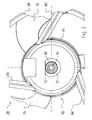
- Fig. 1 shows a longitudinal section through an axial fan 20 with a motor 21 according to a preferred embodiment of the invention on a greatly enlarged scale with an approximately five times magnification.
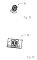
- the fan 20 in FIG. 13 is shown by way of example on a scale of approximately 1: 1.
- the motor 21 is arranged in an air guide tube 80 and has an outer rotor 22 and an inner stator 50.
- the outer rotor 22 has a rotor bell 24, on whose outer circumference a fan 23 with fan blades 26 is provided.
- a rotor magnet 28 is fixed on a soft ferromagnetic return element 27, which is e.g. can be magnetized four-pole.
- the rotor bell 24 has a bottom 30 in which an upper shaft end 32 of a rotor shaft 34 is fixed, which has a lower, free shaft end 35.
- the shaft 34 is made of steel and the rotor bell 24 made of plastic.
- the rotor bell 34 is fixed by plastic injection at the upper end of the shaft 32.
- the inner stator 50 which is described in detail in FIGS. 2 to 11, has a laminated stator core 52 with a plastic coating 77, which together form a bearing tube 70 for the rotatable mounting of the rotor shaft 34.
- a plastic part 90 'in the form of a first axial extension of the plastic coating 77 with a bearing 72 is arranged at one end 71' of the laminated stator core 52.
- a plastic part 90" in the form of a second axial extension is arranged, in which a bearing 76 is located.
- the plastic coating 77 and the projections 90 'and 90 " are made in one piece, with the bearing 72 being secured by plastic spraying in the extension 90' and held in a form-fitting manner by this
- the extension 90 ' can be produced independently of the plastic coating 77 and can be attached to it in a simple operation, for example
- the bearing 76 may also be optionally injected into or pressed into the extension 90 ".
- the bearings 72 and 76 are preferably designed as rolling bearings, but not limited to a particular type of bearing. Rather, different types of bearings can be used, eg plain bearings.
- the rolling bearing 72 has an inner ring 72 'and an outer ring 72 ", and the rolling bearing 76 has an inner ring 76' and an outer ring 76".
- the rotatably mounted in the rolling bearings 72 and 76 rotor shaft 34 is held there by a support member or securing element 92 and a compression spring 94.
- the support member 92 such as a snap-action disc or other locking member is engaged at the lower end 35 of the shaft 34 in an annular groove.
- the spring 94 is clamped between the inner ring 72 'of the rolling bearing 72 and the locking member 92. Through them, a conical extension of the bottom 30 of the rotor bell 24 is pressed against the inner ring 76 'of the rolling bearing 76, so that the shaft 34 in the rolling bearings 72 and 76 of the inner stator 50th is strained. This effect of the spring 94 is assisted by the fact that the rotor magnet 28 is offset against the stator lamination 52 down, creating a magnetic train on the outer rotor 22, which pulls it upwards.
- a printed circuit board 46 is arranged with a relatively large electronic component 48, e.g. a MOSFET which is provided for controlling the current in a stator winding 97 of the motor 21.
- a relatively large electronic component 48 e.g. a MOSFET which is provided for controlling the current in a stator winding 97 of the motor 21.
- Other electronic components e.g. a Hall IC, may also be arranged on the printed circuit board 46, to which connection elements 96 for the stator winding 97 are soldered. These connection elements 96 are fixed by plastic injection in a shoulder 95 of the extension 90 '.
- the lower end of the extension 90 ' is connected by pressing with a hub 85 and may additionally glued to this and / or welded. From this hub 85 go out webs 86 'and 86 ", which hold the Heilleitrohr 80.
- Fig. 2 shows a plan view of the hub 85 of the fan 20 of Fig. 1.
- Fig. 2 illustrates the arranged between the hub 85 and the shipsleitrohr 80 webs 86 ', 86 "and 86"', and the extension 90 ', whose free end is connected to the hub 85.
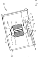
- FIG. 3 shows a perspective longitudinal section through the air duct 80 of the fan 20 with a perspective view of the inner stator 50.
- FIG. 3 illustrates the mounting of the fan 20 according to a preferred embodiment, in which the circuit board 46 with the component 48 in a first step the inner stator 50 is placed before it is attached to the hub 85 in a further step.
- the inner stator 50 has, by way of example, four spacers 59 ', 59 “, 59"', 59 “”. These serve to prevent damage to the stator winding 97 when the inner stator 50 is pressed into the hub 85.
- FIG. 4 shows a spatial representation of the inner stator 50 (FIG. 3) at approximately a tenfold magnification.
- the inner stator 50 is shown in FIG. 12 by way of example on a scale of approximately 1: 1.
- FIG. 4 shows the printed circuit board 46 abutting the shoulder 95 of the extension 90 ', to which the connecting element 96' is soldered, and also the roller bearing 76 fastened in the extension 90 ".
- FIG. this has at its upper end two recesses 75 'and 75 ".
- the laminated stator core 52 includes sheets, three of which are designated 55 ', 55 "and 55"'.
- the stator lamination stack 52 is "packetized", i. its sheets have small holes that are embossed so that they form a unitary block.
- plastic plastic coating 77 contribute, which is injected into the stator lamination 52 and forms together with this the bearing tube 70.
- this plastic forms strip-shaped plastic supports 79 at locations on the outside of the laminated core 52 - two plastic supports are designated by way of example with 79 'and 79 "- which further increase the strength.
- the laminated stator core 52 has, according to FIG. 9, distinct stator poles 52 ', 52 “, 52"', 52 “” which are separated from one another by grooves 54 ', 54 “, 54"', 54 “”, through which the plastic coating 77 extends.
- the stator winding 97 is arranged, see. Fig. 4.
- Fig. 5 shows a side view of the inner stator 50 of Fig. 4, but without the winding 97, and illustrates the shoulder 95 of the extension 90 ', in which the connection element 96' is fixed. In the region of the extension 90 ', in which the component 48 is arranged on the printed circuit board 46, this has a recess 99th
- FIG. 6 shows a longitudinal section through the inner stator 50 and illustrates the recess 99 as well as the bearing tube 70 formed by the plastic coating 77 and the laminated stator core 52.
- the plastic coating 77 forms at the lower end 71 'of the laminated stator core 52 an end layer 73', on which the axial extension 90 'is arranged.
- This has a recess 91 in which the rolling bearing 72 is arranged.
- the recess 91 has a first shoulder 91 'and a second shoulder 91 "opposite the first shoulder
- at least the outer ring 72" of this rolling bearing 72 is injected into the plastic of the extension 90'.
- a first tool is guided from above through the stator lamination stack 52, which holds the upper edge of this outer ring 72 "in front of the plastic injection molding, and its lower edge is held fast by a second tool coming from below. that during plastic injection no plastic can penetrate into the bearing 72.
- the plastic coating 77 forms an end layer or end plate 73" on which the axial extension 90 "is arranged. As can be seen from Fig. 6, the plastic coating 77 and the extensions 90 'and 90" are preferably in one piece educated.
- the extension 90 has a recess 93 for receiving the roller bearing 76. This is preferably pressed into the recess 93, see Fig. 7.
- FIG. 7 shows a sectional view of the inner stator 50 with both rolling bearings 72 and 76.
- FIG. 8 shows another side view of the inner stator 50 analogously to FIG. 5.
- the inner stator 50 is rotated 45 ° to the right in FIG. 8 and shown without the printed circuit board 46 and the component 48.
- These are preferably designed as bronze pins.
- FIG. 9 shows a plan view of the inner stator 50.
- FIG. 9 shows a preferred embodiment of the laminated stator core 52 provided with the plastic coating 77 and illustrates the grooves 54 'provided between the poles 52', 52 ", 52 '" and 52 “' thereof. 54 ", 54"'and 54 "”.
- the final layer 73 'of the plastic coating 77 has at the axial ends of the grooves 54', 54 ", 54" 'and 54 "” apertures 56', 56 ", 56 '” and 56 "”.
- the end layer 73 'lying opposite the end layer 73' has openings 58 ', 58 ", 58"' and 58 ".” These openings on both sides make it possible to arrange the stator winding 97 on the stator lamination stack 52 (not shown in FIG.
- poles 52 ', 52 ", 52'” and 52 “” have an identical structure. For simplicity, therefore, only the structure of the pole 52 'will be described.
- This has a pole core 12 and a pole piece with pole ends or pole horns 14, 16.
- the pole piece 16, on which the plastic support 79 'is applied, has a smaller diameter than the pole piece 14.
- This design is commonly referred to as a reluctance cut and is used to produce a so-called reluctance torque.
- the rotor magnet 28 has a trapezoidal magnetization for cooperation with this stator shape.
- Fig. 10 shows a sectional view of the inner stator 50 along the section line XX of Fig. 9, and Fig. 11 shows a sectional view of the inner stator 50 along the section line XI-XI of Fig. 9.
- Fig. 11 illustrates the openings 56 ', 56'"in the end layer 73 'at the end 71' of the laminated core 52, as well as the openings 58 ', 58"' in the final layer 73 "at the end 71".
- the fan as shown in Fig. 13, can be operated by the described type of storage at a speed of 15,000 rev / min.
- the invention preferably relates to an electronically commutated motor (21) which comprises: a permanent magnetic outer rotor (22) having a rotor shaft (34); an inner stator (50) having a stator lamination stack (52) having stator poles (52 ', 52 “, 52"', 52 “") between which slots (54 ', 54 ", 54”', 54 “") are interposed are; a plastic coating (77) which extends through the grooves (54 ', 54 ", 54”', 54 “"), which together with the stator lamination stack (52) has a bearing tube (70) for receiving at least one bearing (72, 76 ) for supporting the rotor shaft (34), and which for the storage of the rotor shaft (34) has a first axial extension (90 ') in which a first bearing (72) is fixed by plastic injection.
- the plastic injection-molded connection preferably has a first shoulder (91 ') and a second shoulder (91 ") for fastening the first bearing (72).
Landscapes
- Engineering & Computer Science (AREA)
- Power Engineering (AREA)
- Mechanical Engineering (AREA)
- General Engineering & Computer Science (AREA)
- Iron Core Of Rotating Electric Machines (AREA)
- Connection Of Motors, Electrical Generators, Mechanical Devices, And The Like (AREA)
- Motor Or Generator Frames (AREA)
Abstract
Description
Die Erfindung betrifft einen elektronisch kommutierten Motor, insbesondere einen Klein-oder Kleinstmotor. Solche Motoren werden bevorzugt in Klein- bzw. Kleinstlüftern verwendet.The invention relates to an electronically commutated motor, in particular a small or micro motor. Such motors are preferably used in small and micro fans.
Klein- und Kleinstlüfter haben in der Regel sehr geringe Abmessungen und dementsprechend ein sehr geringes Gewicht. Beispielsweise haben die Lüfter der ebm-papst Serie 250 Abmessungen von 8 x 25 x 25 mm und ein Gewicht von annähernd 5 g. Bei Lüftern der ebm-papst Serie 400 betragen die Abmessungen 20 x 40 x 40 mm und das Gewicht beträgt weniger als 30 g. Die Motoren sind korrespondierend hierzu noch kleiner und wiegen noch weniger.Small and very small fans usually have very small dimensions and therefore a very low weight. For example, the fans of the ebm-papst 250 series have dimensions of 8 x 25 x 25 mm and a weight of approximately 5 g. For fans of the ebm-papst 400 series, the dimensions are 20 x 40 x 40 mm and the weight is less than 30 g. The engines are correspondingly even smaller and weigh even less.
Bei derartigen Motoren muss die Montage einfach und unkompliziert sein, um eine kostengünstige Herstellung durch einen hohen Automatisierungsgrad zu ermöglichen. Darüber hinaus kann durch eine weitgehende Automatisierung bei der Herstellung eine gleichmäßige Qualität erzielt werden, welche für eine hohe mittlere Lebensdauer Voraussetzung ist.In such motors, the assembly must be simple and uncomplicated to allow cost-effective production by a high degree of automation. In addition, can be achieved by a high degree of automation in the production of a uniform quality, which is a prerequisite for a high average life.
Es ist deshalb eine Aufgabe der Erfindung, einen neuen Klein- oder Kleinstmotor bereit zu stellen.It is therefore an object of the invention to provide a new small or micro motor.
Nach der Erfindung wird diese Aufgabe gelöst durch einen Motor gemäß Anspruch 1 und ein Verfahren gemäß Anspruch 22. Ein solcher Motor lässt sich sehr kompakt bauen und ermöglicht einen Betrieb mit hohen Drehzahlen, also hoher Leistung.According to the invention, this object is achieved by an engine according to claim 1 and a method according to
Bevorzugte Ausführungsformen sind Gegenstand der Unteransprüche.Preferred embodiments are subject of the dependent claims.
Weitere Einzelheiten und vorteilhafte Weiterbildungen der Erfindung ergeben sich aus den im folgenden beschriebenen und in den Zeichnungen dargestellten, in keiner Weise als Einschränkung der Erfindung zu verstehenden Ausführungsbeispielen, sowie aus den Unteransprüchen. Es zeigt:
- Fig. 1
- einen Längsschnitt durch einen Lüfter, welcher von einem Klein- oder Kleinstmotor nach einer Ausführungsform der Erfindung angetrieben wird,
- Fig. 2
- eine stark vergrößerte Draufsicht auf die Nabe des Lüfters der Fig. 1,
- Fig. 3
- einen perspektivisch dargestellten Längsschnitt durch das Luftleitrohr des Lüfters der Fig. 1 mit einer ebenfalls perspektivischen Darstellung des Innenstators,
- Fig. 4
- eine perspektivische Darstellung des Innenstators der Fig. 1 mit Leiterplatte und MOSFET 48,
- Fig. 5
- eine Seitenansicht des Innenstators der Fig. 4,
- Fig. 6
- eine Schnittansicht des Innenstators der Fig. 4 mit einem der beiden Wälzlager, und mit einer Statorwicklung,
- Fig. 7
- eine Schnittansicht des Innenstators der Fig. 6 mit beiden Wälzlagern,
- Fig. 8
- eine Seitenansicht des Innenstators der Fig. 1 mit
eingespritzten Anschlusselementen 96, - Fig. 9
- eine Draufsicht auf den Innenstator von Fig. 8, gesehen in Richtung des Pfeiles IX der Fig. 8,
- Fig. 10
- einen Schnitt, gesehen längs der Linie X-X der Fig. 9,
- Fig. 11
- einen Schnitt, gesehen längs der Linie XI-XI der Fig. 9,
- Fig. 12
- eine perspektivische Darstellung des Innenstators der Fig. 4 etwa in natürlicher Größe, und
- Fig. 13
- einen Längsschnitt durch den Lüfter der Fig. 1 etwa in natürlicher Größe.
- Fig. 1
- a longitudinal section through a fan, which is driven by a small or micro motor according to an embodiment of the invention,
- Fig. 2
- a greatly enlarged plan view of the hub of the fan of Fig. 1,
- Fig. 3
- 1 shows a perspective view of a longitudinal section through the air duct of the fan of FIG. 1 with a likewise perspective view of the inner stator;
- Fig. 4
- 3 a perspective view of the inner stator of FIG. 1 with printed circuit board and
MOSFET 48, FIG. - Fig. 5
- a side view of the inner stator of Fig. 4,
- Fig. 6
- 4 shows a sectional view of the inner stator of FIG. 4 with one of the two roller bearings, and with a stator winding,
- Fig. 7
- 5 a sectional view of the inner stator of FIG. 6 with two roller bearings, FIG.
- Fig. 8
- 1 is a side view of the inner stator of FIG. 1 with injected
connection elements 96, - Fig. 9
- 8 is a plan view of the inner stator of FIG. 8, seen in the direction of the arrow IX of FIG. 8;
- Fig. 10
- a section, taken along the line XX of FIG. 9,
- Fig. 11
- a section, taken along the line XI-XI of Fig. 9,
- Fig. 12
- a perspective view of the inner stator of FIG. 4 approximately in natural size, and
- Fig. 13
- a longitudinal section through the fan of FIG. 1 approximately in natural size.
In der nachfolgenden Beschreibung beziehen sich die Begriffe links, rechts, oben und unten auf die jeweilige Zeichnungsfigur und können in Abhängigkeit von einer jeweils gewählten Ausrichtung (Hochformat oder Querformat) von einer Zeichnungsfigur zur nächsten variieren. Gleiche oder gleich wirkende Teile werden in den verschiedenen Figuren mit denselben Bezugszeichen bezeichnet und gewöhnlich nur einmal beschrieben.In the following description, the terms left, right, up and down refer to the respective drawing figure, and may vary from one drawing figure to the next, depending on a particular orientation (portrait or landscape). Identical or equivalent parts are denoted by the same reference numerals in the various figures and usually described only once.
Fig. 1 zeigt einen Längsschnitt durch einen Axiallüfter 20 mit einem Motor 21 gemäß einer bevorzugten Ausführungsform der Erfindung in stark vergrößertem Maßstab mit einer etwa fünffachen Vergrößerung. Um die für Klein- und Kleinstlüfter erforderlichen geringen Abmessungen zu verdeutlichen, ist der Lüfter 20 in Fig. 13 beispielhaft im Maßstab von etwa 1:1 gezeigt. Fig. 1 shows a longitudinal section through an
Der Motor 21 ist in einem Luftleitrohr 80 angeordnet und hat einen Außenrotor 22 und einen Innenstator 50. Der Außenrotor 22 hat eine Rotorglocke 24, an deren Außenumfang ein Lüfterrad 23 mit Lüfterflügeln 26 vorgesehen ist. Am inneren Umfang der Rotorglocke 24 ist auf einem weichferromagnetischen Rückschlusselement 27 ein Rotormagnet 28 befestigt, der z.B. vierpolig magnetisiert sein kann. Die Rotorglocke 24 hat einen Boden 30, in dem ein oberes Wellenende 32 einer Rotorwelle 34 befestigt ist, die ein unteres, freies Wellenende 35 hat. Bevorzugt ist die Welle 34 aus Stahl und die Rotorglocke 24 aus Kunststoff. Die Rotorglocke 34 ist durch Kunststoffspritzen am oberen Wellenende 32 befestigt.The
Der Innenstator 50, welcher bei Fig. 2 bis Fig. 11 im Detail beschrieben wird, hat ein Statorblechpaket 52 mit einer Kunststoffbeschichtung 77, welche zusammen ein Lagerrohr 70 zur drehbaren Lagerung der Rotorwelle 34 bilden. Hierzu ist an einem Ende 71' des Statorblechpakets 52 ein Kunststoffteil 90' in der Form eines ersten axialen Fortsatzes der Kunststoffbeschichtung 77 mit einem Lager 72 angeordnet. Am anderen Ende 71" des Statorblechpakets 52 ist ein Kunststoffteil 90" in der Form eines zweiten axialen Fortsatzes angeordnet, in dem sich ein Lager 76 befindet.The
Gemäß einer bevorzugten Ausführungsform der Erfindung sind die Kunststoffbeschichtung 77 und die Fortsätze 90' und 90" einteilig ausgeführt, wobei das Lager 72 durch Kunststoffspritzen im Fortsatz 90' befestigt und durch diesen formschlüssig gehalten wird. Alternativ hierzu kann der Fortsatz 90' als separates Bauteil derart ausgeführt werden, dass das Lager 72 durch Einpressen in ihm verankert werden kann. Hierbei kann der Fortsatz 90' unabhängig von der Kunststoffbeschichtung 77 hergestellt werden und in einem einfachen Arbeitsschritt beispielsweise auf diese aufgesteckt werden. Hierzu kann der Fortsatz 90' ein oder mehrere Führungselemente aufweisen, welche solch ein Aufstecken erleichtern. Das Lager 76 kann ebenfalls wahlweise in den Fortsatz 90" eingespritzt oder in diesen eingepresst werden.According to a preferred embodiment of the invention, the
Die Lager 72 und 76 sind bevorzugt als Wälzlager ausgeführt, jedoch nicht auf einen bestimmten Lagertyp beschränkt. Vielmehr können verschiedene Lagertypen verwendet werden, z.B. Gleitlager. Das Wälzlager 72 hat einen Innenring 72' und einen Außenring 72", und das Wälzlager 76 hat einen Innenring 76' und einen Außenring 76". Die in den Wälzlagern 72 und 76 drehbar gelagerte Rotorwelle 34 wird dort durch ein Stützglied bzw. Sicherungselement 92 und eine Druckfeder 94 gehalten. Das Stützglied 92, beispielsweise eine Schnappscheibe oder ein sonstiges Rastglied, ist am unteren Ende 35 der Welle 34 in eine Ringnut eingerastet. Die Feder 94 ist zwischen dem Innenring 72' des Wälzlagers 72 und dem Rastglied 92 eingespannt. Durch sie wird ein konischer Fortsatz des Bodens 30 der Rotorglocke 24 gegen den Innenring 76' des Wälzlagers 76 gedrückt, sodass die Welle 34 in den Wälzlagern 72 und 76 des Innenstators 50 verspannt wird. Diese Wirkung der Feder 94 wird dadurch unterstützt, dass der Rotormagnet 28 gegen das Statorblechpaket 52 nach unten versetzt ist, wodurch ein magnetischer Zug auf den Außenrotor 22 entsteht, welcher diesen nach oben zieht.The
Am äußeren Umfang 74 des Fortsatzes 90' ist eine Leiterplatte 46 mit einem relativ großen elektronischen Bauteil 48 angeordnet, z.B. einem MOSFET, welcher zum Steuern des Stromes in einer Statorwicklung 97 des Motors 21 vorgesehen ist. Weitere elektronische Bauelemente, z.B. ein Hall-IC, können ebenfalls auf der Leiterplatte 46 angeordnet sein, an welcher Anschlusselemente 96 für die Statorwicklung 97 angelötet sind. Diese Anschlusselemente 96 sind durch Kunststoffspritzen in einer Schulter 95 des Fortsatzes 90' befestigt.On the
Das untere Ende des Fortsatzes 90' ist durch Einpressen mit einer Nabe 85 verbunden und kann zusätzlich an dieser verklebt und/oder angeschweißt sein. Von dieser Nabe 85 gehen Stege 86' und 86" aus, welche das Luftleitrohr 80 halten.The lower end of the extension 90 'is connected by pressing with a
Fig. 2 zeigt eine Draufsicht auf die Nabe 85 des Lüfters 20 der Fig. 1. Fig. 2 verdeutlicht die zwischen der Nabe 85 und dem Luftleitrohr 80 angeordneten Stege 86', 86" und 86"', und den Fortsatz 90', dessen freies Ende mit der Nabe 85 verbunden ist. Fig. 2 shows a plan view of the
Fig. 3 zeigt einen perspektivischen Längsschnitt durch das Luftleitrohr 80 des Lüfters 20 mit einer perspektivischen Darstellung des Innenstators 50. Fig. 3 verdeutlicht die Montage des Lüfters 20 gemäß einer bevorzugten Ausführungsform, bei welcher in einem ersten Arbeitsschritt die Leiterplatte 46 mit dem Bauteil 48 auf dem Innenstator 50 angeordnet wird, bevor dieser in einem weiteren Arbeitsschritt an der Nabe 85 befestigt wird. 3 shows a perspective longitudinal section through the
Wie aus Fig. 3 ersichtlich, weist der Innenstator 50 beispielhaft vier Abstandhalter 59', 59", 59"', 59"" auf. Diese dienen dazu, eine Beschädigung der Statorwicklung 97 beim Einpressen des Innenstators 50 in die Nabe 85 zu verhindern.As can be seen in FIG. 3, the
Fig. 4 zeigt eine räumliche Darstellung des Innenstators 50 (Fig. 3) in etwa zehnfacher Vergrößerung. Zur Verdeutlichung ist der Innenstator 50 in Fig. 12 beispielhaft im Maßstab von etwa 1:1 gezeigt. FIG. 4 shows a spatial representation of the inner stator 50 (FIG. 3) at approximately a tenfold magnification. For clarity, the
Fig. 4 zeigt die an der Schulter 95 des Fortsatzes 90' anliegende Leiterplatte 46, an der das Anschlusselement 96' angelötet ist, sowie das im Fortsatz 90" befestigte Wälzlager 76. Um das Einpressen des Wälzlagers 76 in den Fortsatz 90" zu erleichtern, hat dieser an seinem oberen Ende zwei Aussparungen 75' und 75".4 shows the printed
Das Statorblechpaket 52 enthält Bleche, von denen drei mit 55', 55" und 55"' bezeichnet sind. Das Statorblechpaket 52 ist "packetiert", d.h. seine Bleche haben kleine Löcher, die verprägt werden, sodass Sie einen einheitlichen Block bilden. Zur Festigkeit dieses Blocks kann auch Kunststoff der Kunststoffbeschichtung 77 beitragen, der in das Statorblechpaket 52 eingespritzt wird und zusammen mit diesem das Lagerrohr 70 bildet. Gemäß Fig. 4 bildet dieser Kunststoff an Stellen auf der Außenseite des Blechpakets 52 streifenförmige Kunststoffauflagen 79 aus - zwei Kunststoffauflagen sind beispielhaft mit 79' und 79" bezeichnet -, welche die Festigkeit weiter erhöhen.The
Das Statorblechpaket 52 hat gemäß Fig. 9 ausgeprägte Statorpole 52', 52", 52"', 52"", welche durch Nuten 54', 54", 54"', 54"" voneinander getrennt sind, durch welche sich die Kunststoffbeschichtung 77 erstreckt. Auf den Statorpolen 52', 52", 52"', 52"" ist die Statorwicklung 97 angeordnet, vgl. Fig. 4.The
Fig. 5 zeigt eine Seitenansicht des Innenstators 50 von Fig. 4, aber ohne die Wicklung 97, und verdeutlicht die Schulter 95 des Fortsatzes 90', in welcher das Anschlusselement 96' befestigt ist. In dem Bereich des Fortsatzes 90', in dem das Bauteil 48 auf der Leiterplatte 46 angeordnet ist, hat dieser eine Aussparung 99. Fig. 5 shows a side view of the
Fig. 6 zeigt einen Längsschnitt durch den Innenstator 50 und verdeutlicht die Aussparung 99 sowie das von der Kunststoffbeschichtung 77 und dem Statorblechpaket 52 gebildete Lagerrohr 70. FIG. 6 shows a longitudinal section through the
Die Kunststoffbeschichtung 77 bildet am unteren Ende 71' des Statorblechpakets 52 eine Endschicht 73', an welcher der axiale Fortsatz 90' angeordnet ist. Dieser hat eine Ausnehmung 91, in der das Wälzlager 72 angeordnet ist. Die Ausnehmung 91 hat eine erste Schulter 91' und eine zweite Schulter 91 ", welche der ersten Schulter gegenüberliegt. Wie bei Fig. 1 erwähnt, wird zumindest der Außenring 72" dieses Wälzlagers 72 in den Kunststoff des Fortsatzes 90' eingespritzt. Hierzu wird vor dem Kunststoffspritzen ein erstes Werkzeug von oben durch das Statorblechpaket 52 geführt, welches den oberen Rand dieses Außenrings 72" festhält. Sein unterer Rand wird von einem von unten kommenden zweiten Werkzeug festgehalten. Die beiden Werkzeuge dichten das Wälzlager 72 hierbei derart ab, dass beim Kunststoffspritzen kein Kunststoff in das Lager 72 eindringen kann.The
Am oberen Ende 71" des Statorblechpakets 52 bildet die Kunststoffbeschichtung 77 eine Endschicht oder Stirnscheibe 73", an welcher der axiale Fortsatz 90" angeordnet ist. Wie aus Fig. 6 ersichtlich, sind die Kunststoffbeschichtung 77 und die Fortsätze 90' und 90" bevorzugt einteilig ausgebildet.At the
Der Fortsatz 90" hat eine Ausnehmung 93 zur Aufnahme des Wälzlagers 76. Dieses wird bevorzugt in die Ausnehmung 93 eingepresst, vgl. Fig. 7.The
Fig. 7 zeigt eine Schnittansicht des Innenstators 50 mit beiden Wälzlagern 72 und 76. FIG. 7 shows a sectional view of the
Fig. 8 zeigt analog zu Fig. 5 eine andere Seitenansicht des Innenstators 50. Im Gegensatz zur Seitenansicht der Fig. 5 ist der Innenstator 50 in Fig. 8 um 45° nach rechts gedreht und ohne die Leiterplatte 46 und das Bauteil 48 dargestellt. Dadurch sieht man in Fig. 8 die zwischen den Polen 52' und 52"" liegende Nut 54"" und die in die Schulter 95 eingespritzten Anschlusselemente 96" und 96"'. Diese sind bevorzugt als Bronzestifte ausgeführt. FIG. 8 shows another side view of the
Fig. 9 zeigt eine Draufsicht auf den Innenstator 50. Fig. 9 zeigt eine bevorzugte Ausführungsform des mit der Kunststoffbeschichtung 77 versehenen Statorblechpakets 52 und verdeutlicht die zwischen dessen Polen 52', 52", 52'" und 52"" vorgesehenen Nuten 54', 54", 54"' und 54"". 9 shows a plan view of the
Wie aus Fig. 9 ersichtlich, hat die Endschicht 73' der Kunststoffbeschichtung 77 an den axialen Enden der Nuten 54', 54", 54"' und 54"" Durchbrechungen 56', 56", 56'" und 56"". Analog hierzu hat die der Endschicht 73' gegenüberliegende Endschicht 73" Durchbrechungen 58', 58", 58"' und 58"". Diese beidseitigen Durchbrechungen ermöglichen die Anordnung der - in Fig. 9 nicht gezeigten - Statorwicklung 97 auf dem Statorblechpaket 52.As can be seen in Figure 9, the final layer 73 'of the
Alle Pole 52', 52", 52'" und 52"" haben einen identischen Aufbau. Zur Vereinfachung wird deshalb lediglich der Aufbau des Pols 52' beschrieben. Dieser hat einen Polkern 12 und einen Polschuh mit Polenden oder Polhörnern 14, 16. Das Polhorn 16, auf das die Kunststoffauflage 79' aufgebracht ist, hat einen geringeren Durchmesser als das Polhorn 14. Diese Formgebung wird üblicherweise als Reluktanzschnitt bezeichnet und dient zur Erzeugung eines so genannten Reluktanzmoments. Der Rotormagnet 28 hat zum Zusammenwirken mit dieser Statorform eine trapezförmige Magnetisierung.All
Fig. 10 zeigt eine Schnittansicht des Innenstators 50 entlang der Schnittlinie X-X der Fig. 9, und Fig. 11 zeigt eine Schnittansicht des Innenstators 50 entlang der Schnittlinie XI-XI der Fig. 9. Fig. 11 verdeutlicht die Durchbrechungen 56', 56'" in der Endschicht 73' am Ende 71' des Blechpakets 52, sowie die Durchbrechungen 58', 58"' in der Endschicht 73" an dessen Ende 71". Fig. 10 shows a sectional view of the
Es hat sich gezeigt, dass der Lüfter, wie er in Fig. 13 dargestellt ist, durch die beschriebene Art der Lagerung mit einer Drehzahl von 15.000 U/min betrieben werden kann.It has been found that the fan, as shown in Fig. 13, can be operated by the described type of storage at a speed of 15,000 rev / min.
Die Erfindung betrifft bevorzugt einen elektronisch kommutierter Motor (21), welcher aufweist: Einen permanentmagnetischen Außenrotor (22) mit einer Rotorwelle (34); einen Innenstator (50) mit einem Statorblechpaket (52), welches Statorpole (52', 52", 52"', 52"") aufweist, zwischen denen Nuten (54', 54", 54"', 54"") angeordnet sind; eine Kunststoffbeschichtung (77), welche sich durch die Nuten (54', 54", 54"', 54"") erstreckt, welche zusammen mit dem Statorblechpaket (52) ein Lagerrohr (70) zur Aufnahme mindestens eines Lagers (72, 76) zur Lagerung der Rotorwelle (34) bildet, und welche für die Lagerung der Rotorwelle (34) einen ersten axialen Fortsatz (90') aufweist, in dem ein erstes Lager (72) durch Kunststoffspritzen befestigt ist. Bevorzugt weist die Kunststoffspritzverbindung eine erste Schulter (91') und eine zweite Schulter (91 ") zur Befestigung des ersten Lagers (72) auf.The invention preferably relates to an electronically commutated motor (21) which comprises: a permanent magnetic outer rotor (22) having a rotor shaft (34); an inner stator (50) having a stator lamination stack (52) having stator poles (52 ', 52 ", 52"', 52 "") between which slots (54 ', 54 ", 54"', 54 "") are interposed are; a plastic coating (77) which extends through the grooves (54 ', 54 ", 54"', 54 ""), which together with the stator lamination stack (52) has a bearing tube (70) for receiving at least one bearing (72, 76 ) for supporting the rotor shaft (34), and which for the storage of the rotor shaft (34) has a first axial extension (90 ') in which a first bearing (72) is fixed by plastic injection. The plastic injection-molded connection preferably has a first shoulder (91 ') and a second shoulder (91 ") for fastening the first bearing (72).
Naturgemäß sind im Rahmen der vorliegenden Erfindung vielfache Abwandlungen und Modifikationen möglich.Naturally, many modifications and modifications are possible within the scope of the present invention.
Claims (25)
bei welchem das erste Lager (72) in dem ersten axialen Fortsatz (90') durch eine Kunststoffspritzverbindung befestigt ist.Motor according to claim 1,
wherein the first bearing (72) is secured in the first axial extension (90 ') by a plastic injection molding connection.
und welche einen zweiten axialen Fortsatz (90") mit einer zweiten Ausnehmung (93) zur Aufnahme eines zweiten Lagers (76) für die Lagerung der Rotorwelle (34) aufweist.A motor as claimed in any one of the preceding claims, wherein the plastic coating (77) forms at a second end (71 ") of the stator lamination stack (52) a second end layer (73") which is provided at the axial ends of the grooves (54 ', 54 ", 54 "', 54"") has apertures (58', 58", 58 "', 58""),
and which has a second axial extension (90 ") with a second recess (93) for receiving a second bearing (76) for supporting the rotor shaft (34).
mit einem Innenstator (50) mit einem Statorblechpaket (52), welches Statorpole (52', 52", 52"', 52"") aufweist, zwischen denen Nuten (54', 54", 54"', 54"") angeordnet sind,
mit einer Kunststoffbeschichtung (77),
welche sich durch die Nuten (54', 54", 54"', 54"") erstreckt und
welche zusammen mit dem Statorblechpaket (52) ein Lagerrohr (70) zur Aufnahme mindestens eines ersten Lagers (72, 76) zur Lagerung der Rotorwelle (34) bildet,
bei welchem Verfahren das erste Lager (72) in der Kunststoffbeschichtung durch Kunststoffspritzen befestigt wird.Method for producing an electronically commutated motor
comprising an inner stator (50) with a stator lamination stack (52) having stator poles (52 ', 52 ", 52"', 52 "") between which slots (54 ', 54 ", 54"', 54 "") are arranged
with a plastic coating (77),
which extends through the grooves (54 ', 54 ", 54"', 54 "") and
which together with the stator lamination stack (52) forms a bearing tube (70) for receiving at least one first bearing (72, 76) for supporting the rotor shaft (34),
In which method, the first bearing (72) is secured in the plastic coating by plastic spraying.
bei welchem das erste Lager (72) durch Kunststoffspritzen in der Weise befestigt wird, dass es zwischen einer ersten Schulter (91') und einer zweiten Schulter (91") der Kunststoffbeschichtung (77) gehalten wird.Method according to claim 22,
in which the first bearing (72) is fixed by plastic injection in such a way that it is held between a first shoulder (91 ') and a second shoulder (91 ") of the plastic coating (77).
mit einer Kunststoffspritzeinreichtung, welche ein erstes Spritzwerkzeug und ein zweites Spritzwerkzeug aufweist,
welches Verfahren die folgenden Schritte aufweist:
with a plastic injection device, which has a first injection molding tool and a second injection molding tool,
which method comprises the following steps:
Applications Claiming Priority (1)
| Application Number | Priority Date | Filing Date | Title |
|---|---|---|---|
| DE202006002068 | 2006-02-03 |
Publications (2)
| Publication Number | Publication Date |
|---|---|
| EP1816727A2 true EP1816727A2 (en) | 2007-08-08 |
| EP1816727A3 EP1816727A3 (en) | 2011-04-06 |
Family
ID=37864492
Family Applications (1)
| Application Number | Title | Priority Date | Filing Date |
|---|---|---|---|
| EP20070001240 Withdrawn EP1816727A3 (en) | 2006-02-03 | 2007-01-20 | Electric motor |
Country Status (2)
| Country | Link |
|---|---|
| US (1) | US7859145B2 (en) |
| EP (1) | EP1816727A3 (en) |
Cited By (4)
| Publication number | Priority date | Publication date | Assignee | Title |
|---|---|---|---|---|
| EP3141749A4 (en) * | 2014-05-07 | 2017-05-31 | Panasonic Corporation | Sealed compressor and refrigeration device |
| CN113669272A (en) * | 2020-05-15 | 2021-11-19 | 广达电脑股份有限公司 | Fan module and motor |
| US11437900B2 (en) | 2019-12-19 | 2022-09-06 | Black & Decker Inc. | Modular outer-rotor brushless motor for a power tool |
| US11757330B2 (en) | 2019-12-19 | 2023-09-12 | Black & Decker, Inc. | Canned outer-rotor brushless motor for a power tool |
Families Citing this family (10)
| Publication number | Priority date | Publication date | Assignee | Title |
|---|---|---|---|---|
| EP1816727A3 (en) * | 2006-02-03 | 2011-04-06 | ebm-papst St. Georgen GmbH & Co. KG | Electric motor |
| TWI340797B (en) * | 2007-08-24 | 2011-04-21 | Delta Electronics Inc | Fan, motor and bush thereof |
| JP5472683B2 (en) * | 2009-05-11 | 2014-04-16 | 日立工機株式会社 | Electric tool |
| US8283841B2 (en) * | 2010-06-23 | 2012-10-09 | Lin Engineering | Motor end cap with interference fit |
| US20150042189A1 (en) | 2013-08-09 | 2015-02-12 | Black & Decker Inc. | Brush assembly for an electric motor |
| US9866078B2 (en) | 2014-01-29 | 2018-01-09 | Black & Decker Inc. | Brush assembly mount |
| US9991770B2 (en) | 2013-08-09 | 2018-06-05 | Black & Decker Inc. | Spring post for brush card for a power tool |
| DE102013227054A1 (en) * | 2013-12-23 | 2015-06-25 | Robert Bosch Gmbh | Stator with an encapsulation and electric machine with the stator |
| WO2016006229A1 (en) * | 2014-07-07 | 2016-01-14 | パナソニックIpマネジメント株式会社 | Sealed compressor and refrigeration device using the same |
| CN106464066B (en) * | 2014-09-09 | 2019-03-26 | 株式会社Top | Motor |
Citations (1)
| Publication number | Priority date | Publication date | Assignee | Title |
|---|---|---|---|---|
| US20020113519A1 (en) | 2001-02-22 | 2002-08-22 | Brown Fred A. | Stator with molded insulator |
Family Cites Families (23)
| Publication number | Priority date | Publication date | Assignee | Title |
|---|---|---|---|---|
| US3200269A (en) * | 1961-01-31 | 1965-08-10 | Melvin M Goldstein | Self charging nuclear battery |
| DE3123814A1 (en) * | 1980-07-22 | 1982-04-01 | VEB Elektromotorenwerk Hartha, DDR 7302 Hartha | Stator construction for small electrical machines, especially electronic motors |
| US4604665A (en) * | 1980-12-05 | 1986-08-05 | Papst-Motoren Gmbh & Co. Kg | Driving mechanism for magnetic hard disc |
| DE3404466A1 (en) * | 1984-02-08 | 1985-08-08 | Ebm Elektrobau Mulfingen Gmbh & Co, 7119 Mulfingen | EXTERNAL ROTOR MOTOR |
| US4682065A (en) * | 1985-11-13 | 1987-07-21 | Nidec-Torin Corporation | Molded plastic motor housing with integral stator mounting and shaft journalling projection |
| DE3809277B4 (en) * | 1987-09-21 | 2005-02-24 | Papst Licensing Gmbh & Co. Kg | Bearing arrangement for axially compact micro fan |
| US5170086A (en) * | 1987-12-10 | 1992-12-08 | Papst Motoren Gmbh | Electric motor with toothed disk to secure stator core |
| US4934041A (en) * | 1988-07-27 | 1990-06-19 | Nidec Corporation | Method of assembling brushless electric motors |
| TW263629B (en) * | 1992-05-27 | 1995-11-21 | Nihon Densan Kk | |
| US5682074A (en) * | 1994-03-02 | 1997-10-28 | Northrop Grumman Corporation | Electric vehicle motor |
| US5770907A (en) * | 1995-08-14 | 1998-06-23 | Itt Automotive Electrical Systems, Inc. | Windshield wiper motor for use in a vehicle and method for manufacturing |
| US5666011A (en) * | 1995-09-08 | 1997-09-09 | Hong; Ching-Shen | Miniature fan motor assembly |
| EP0945967B1 (en) * | 1998-03-21 | 2006-10-11 | ebm-papst St. Georgen GmbH & Co. KG | Electronically commutated motor |
| US6050786A (en) * | 1998-08-19 | 2000-04-18 | Delta Electronics, Inc. | Heat dissipation structure of a fan unit |
| DE29914693U1 (en) * | 1998-09-01 | 2000-01-13 | Papst Motoren Gmbh & Co Kg | Axial fan with an external rotor drive motor |
| US6318976B1 (en) * | 2000-04-10 | 2001-11-20 | Hsieh Hsin-Mao | Heat dissipation fan |
| DE10052039C2 (en) * | 2000-10-20 | 2002-10-31 | Ebm Werke Gmbh & Co Kg | Axial shaft lock and locking element |
| EP1382106A4 (en) * | 2001-03-16 | 2005-03-09 | Steven E Howe | Alternator and method of manufacture |
| JP2004040926A (en) * | 2002-07-04 | 2004-02-05 | Minebea Co Ltd | Fan motor |
| ATE405754T1 (en) * | 2002-08-30 | 2008-09-15 | Ebm Papst St Georgen Gmbh & Co | ARRANGEMENT WITH A PLAIN BEARING |
| DE20301009U1 (en) * | 2003-01-23 | 2004-05-27 | Papst-Motoren Gmbh & Co. Kg | External rotor motor, especially small or very small fans |
| US7841541B2 (en) * | 2003-11-12 | 2010-11-30 | Ebm-Papst St. Georgen Gmbh & Co. Kg | Fan having a sensor |
| EP1816727A3 (en) * | 2006-02-03 | 2011-04-06 | ebm-papst St. Georgen GmbH & Co. KG | Electric motor |
-
2007
- 2007-01-20 EP EP20070001240 patent/EP1816727A3/en not_active Withdrawn
- 2007-01-30 US US11/668,508 patent/US7859145B2/en not_active Expired - Fee Related
Patent Citations (1)
| Publication number | Priority date | Publication date | Assignee | Title |
|---|---|---|---|---|
| US20020113519A1 (en) | 2001-02-22 | 2002-08-22 | Brown Fred A. | Stator with molded insulator |
Cited By (5)
| Publication number | Priority date | Publication date | Assignee | Title |
|---|---|---|---|---|
| EP3141749A4 (en) * | 2014-05-07 | 2017-05-31 | Panasonic Corporation | Sealed compressor and refrigeration device |
| US10001116B2 (en) | 2014-05-07 | 2018-06-19 | Panasonic Corporation | Sealed compressor and refrigeration device |
| US11437900B2 (en) | 2019-12-19 | 2022-09-06 | Black & Decker Inc. | Modular outer-rotor brushless motor for a power tool |
| US11757330B2 (en) | 2019-12-19 | 2023-09-12 | Black & Decker, Inc. | Canned outer-rotor brushless motor for a power tool |
| CN113669272A (en) * | 2020-05-15 | 2021-11-19 | 广达电脑股份有限公司 | Fan module and motor |
Also Published As
| Publication number | Publication date |
|---|---|
| US7859145B2 (en) | 2010-12-28 |
| US20070182261A1 (en) | 2007-08-09 |
| EP1816727A3 (en) | 2011-04-06 |
Similar Documents
| Publication | Publication Date | Title |
|---|---|---|
| EP1816727A2 (en) | Electric motor | |
| EP1620932B1 (en) | Electric machine | |
| DE102004017157B4 (en) | Method for producing a rotor assembly and rotor assembly for an electrical machine | |
| EP2735086B1 (en) | Internal rotor motor | |
| DE112007000201T5 (en) | Slotted cores for a motor stator, motor stator, permanent magnet type synchronous motor, and punch punch punching method for slotted cores | |
| DE102012021042A1 (en) | Rotor and motor | |
| DE102008026648B4 (en) | Rotor for an electronically commutated electric motor, method for producing such a rotor as well as usable in the manufacture of such a rotor intermediate | |
| WO2007033857A1 (en) | Module for a primary part of an electric machine which is excited by a permanent magnet | |
| DE102008032844A1 (en) | Permanent magnetic rotor | |
| EP2084806A1 (en) | Electric motor and method for manufacturing an electric motor for a motor vehicle actuator drive | |
| DE112016006720T5 (en) | Stator, motor, blower, vacuum cleaner and method for mounting a Hall sensor | |
| DE102004017507A1 (en) | Rotor arrangement for an electric machine | |
| EP2398130A2 (en) | Small electric motor | |
| DE102005047771A1 (en) | Rotor arrangement for electrical machine has stacked plates with some openings bridged at outer ends by outer bridges and other openings open at outer end | |
| DE112014007129T5 (en) | A stator core for a rotary electric machine, a rotary electric machine, and a method of manufacturing a rotary electric machine | |
| DE102004054277A1 (en) | Rotor assembly for an electric machine and method of manufacturing a rotor assembly | |
| DE102017103619A1 (en) | Electric motor, inner rotor and rotor plate | |
| WO2013164164A2 (en) | Positioning a permanent magnet in a rotor or stator | |
| DE102009003228B4 (en) | Electric machine | |
| EP2393186A2 (en) | Electric motor | |
| EP3462582A1 (en) | Permanent magnet rotor, method for its production and magnetizing apparatus | |
| EP2704294A1 (en) | Rotor of a permanently excited synchronous machine | |
| DE102015121102A1 (en) | Rotor device for an electric motor and / or generator, rotor and motor with such a rotor device and manufacturing method | |
| WO2013053537A2 (en) | Rotor or stator with a permanent magnet mounted in the radial direction | |
| EP1816729A2 (en) | Electric motor |
Legal Events
| Date | Code | Title | Description |
|---|---|---|---|
| PUAI | Public reference made under article 153(3) epc to a published international application that has entered the european phase |
Free format text: ORIGINAL CODE: 0009012 |
|
| AK | Designated contracting states |
Kind code of ref document: A2 Designated state(s): AT BE BG CH CY CZ DE DK EE ES FI FR GB GR HU IE IS IT LI LT LU LV MC NL PL PT RO SE SI SK TR |
|
| AX | Request for extension of the european patent |
Extension state: AL BA HR MK YU |
|
| PUAL | Search report despatched |
Free format text: ORIGINAL CODE: 0009013 |
|
| AK | Designated contracting states |
Kind code of ref document: A3 Designated state(s): AT BE BG CH CY CZ DE DK EE ES FI FR GB GR HU IE IS IT LI LT LU LV MC NL PL PT RO SE SI SK TR |
|
| AX | Request for extension of the european patent |
Extension state: AL BA HR MK RS |
|
| 17P | Request for examination filed |
Effective date: 20110730 |
|
| AKX | Designation fees paid |
Designated state(s): AT BE BG CH CY CZ DE DK EE ES FI FR GB GR HU IE IS IT LI LT LU LV MC NL PL PT RO SE SI SK TR |
|
| 17Q | First examination report despatched |
Effective date: 20121106 |
|
| RIC1 | Information provided on ipc code assigned before grant |
Ipc: H02K 5/173 20060101ALI20150217BHEP Ipc: F04D 25/06 20060101ALI20150217BHEP Ipc: H02K 1/18 20060101AFI20150217BHEP |
|
| GRAP | Despatch of communication of intention to grant a patent |
Free format text: ORIGINAL CODE: EPIDOSNIGR1 |
|
| INTG | Intention to grant announced |
Effective date: 20150515 |
|
| RIN1 | Information on inventor provided before grant (corrected) |
Inventor name: RAPP, NILS Inventor name: BERROTH, HANSJOERG |
|
| STAA | Information on the status of an ep patent application or granted ep patent |
Free format text: STATUS: THE APPLICATION IS DEEMED TO BE WITHDRAWN |
|
| 18D | Application deemed to be withdrawn |
Effective date: 20150926 |