EP1816693B1 - Negative electrode current collector for lead storage battery and lead storage battery including the same - Google Patents
Negative electrode current collector for lead storage battery and lead storage battery including the same Download PDFInfo
- Publication number
- EP1816693B1 EP1816693B1 EP05806142A EP05806142A EP1816693B1 EP 1816693 B1 EP1816693 B1 EP 1816693B1 EP 05806142 A EP05806142 A EP 05806142A EP 05806142 A EP05806142 A EP 05806142A EP 1816693 B1 EP1816693 B1 EP 1816693B1
- Authority
- EP
- European Patent Office
- Prior art keywords
- lead
- surface layer
- current collector
- electrode current
- negative electrode
- Prior art date
- Legal status (The legal status is an assumption and is not a legal conclusion. Google has not performed a legal analysis and makes no representation as to the accuracy of the status listed.)
- Ceased
Links
- 238000003860 storage Methods 0.000 title abstract description 7
- 239000002344 surface layer Substances 0.000 claims abstract description 116
- 229910052718 tin Inorganic materials 0.000 claims abstract description 63
- 229910045601 alloy Inorganic materials 0.000 claims abstract description 56
- 239000000956 alloy Substances 0.000 claims abstract description 56
- 229910052787 antimony Inorganic materials 0.000 claims abstract description 41
- 239000002253 acid Substances 0.000 claims description 86
- 229910052745 lead Inorganic materials 0.000 claims description 15
- 238000004519 manufacturing process Methods 0.000 abstract description 18
- 229910001245 Sb alloy Inorganic materials 0.000 abstract description 5
- 229910020220 Pb—Sn Inorganic materials 0.000 abstract 1
- 229910020935 Sn-Sb Inorganic materials 0.000 abstract 1
- 229910008757 Sn—Sb Inorganic materials 0.000 abstract 1
- 230000001747 exhibiting effect Effects 0.000 abstract 1
- 238000000034 method Methods 0.000 description 82
- 238000007747 plating Methods 0.000 description 21
- 239000008151 electrolyte solution Substances 0.000 description 17
- 239000000203 mixture Substances 0.000 description 17
- 230000005484 gravity Effects 0.000 description 16
- 238000005266 casting Methods 0.000 description 14
- 230000000694 effects Effects 0.000 description 11
- 238000005096 rolling process Methods 0.000 description 11
- 239000011149 active material Substances 0.000 description 9
- 230000006866 deterioration Effects 0.000 description 9
- QAOWNCQODCNURD-UHFFFAOYSA-N Sulfuric acid Chemical compound OS(O)(=O)=O QAOWNCQODCNURD-UHFFFAOYSA-N 0.000 description 8
- 239000000463 material Substances 0.000 description 8
- YADSGOSSYOOKMP-UHFFFAOYSA-N dioxolead Chemical compound O=[Pb]=O YADSGOSSYOOKMP-UHFFFAOYSA-N 0.000 description 7
- WATWJIUSRGPENY-UHFFFAOYSA-N antimony atom Chemical compound [Sb] WATWJIUSRGPENY-UHFFFAOYSA-N 0.000 description 6
- 238000002474 experimental method Methods 0.000 description 6
- 239000002184 metal Substances 0.000 description 6
- 229910052751 metal Inorganic materials 0.000 description 6
- 238000005260 corrosion Methods 0.000 description 5
- 230000007797 corrosion Effects 0.000 description 5
- ATJFFYVFTNAWJD-UHFFFAOYSA-N Tin Chemical compound [Sn] ATJFFYVFTNAWJD-UHFFFAOYSA-N 0.000 description 4
- 230000007423 decrease Effects 0.000 description 4
- 229910052739 hydrogen Inorganic materials 0.000 description 4
- 239000001257 hydrogen Substances 0.000 description 4
- 238000002844 melting Methods 0.000 description 4
- 230000008018 melting Effects 0.000 description 4
- 239000007774 positive electrode material Substances 0.000 description 4
- 229910014474 Ca-Sn Inorganic materials 0.000 description 3
- UFHFLCQGNIYNRP-UHFFFAOYSA-N Hydrogen Chemical compound [H][H] UFHFLCQGNIYNRP-UHFFFAOYSA-N 0.000 description 3
- 229910000978 Pb alloy Inorganic materials 0.000 description 3
- 229910052785 arsenic Inorganic materials 0.000 description 3
- 229910052791 calcium Inorganic materials 0.000 description 3
- 239000011575 calcium Substances 0.000 description 3
- 239000010410 layer Substances 0.000 description 3
- WABPQHHGFIMREM-UHFFFAOYSA-N lead(0) Chemical compound [Pb] WABPQHHGFIMREM-UHFFFAOYSA-N 0.000 description 3
- 239000007773 negative electrode material Substances 0.000 description 3
- 239000002245 particle Substances 0.000 description 3
- 238000003466 welding Methods 0.000 description 3
- OYPRJOBELJOOCE-UHFFFAOYSA-N Calcium Chemical compound [Ca] OYPRJOBELJOOCE-UHFFFAOYSA-N 0.000 description 2
- 230000015572 biosynthetic process Effects 0.000 description 2
- 230000015556 catabolic process Effects 0.000 description 2
- 238000006731 degradation reaction Methods 0.000 description 2
- 238000010586 diagram Methods 0.000 description 2
- 239000007789 gas Substances 0.000 description 2
- 239000012535 impurity Substances 0.000 description 2
- 229910000464 lead oxide Inorganic materials 0.000 description 2
- YEXPOXQUZXUXJW-UHFFFAOYSA-N oxolead Chemical compound [Pb]=O YEXPOXQUZXUXJW-UHFFFAOYSA-N 0.000 description 2
- 230000001105 regulatory effect Effects 0.000 description 2
- OKTJSMMVPCPJKN-UHFFFAOYSA-N Carbon Chemical compound [C] OKTJSMMVPCPJKN-UHFFFAOYSA-N 0.000 description 1
- HBBGRARXTFLTSG-UHFFFAOYSA-N Lithium ion Chemical compound [Li+] HBBGRARXTFLTSG-UHFFFAOYSA-N 0.000 description 1
- 229910001128 Sn alloy Inorganic materials 0.000 description 1
- 238000009825 accumulation Methods 0.000 description 1
- 229910052782 aluminium Inorganic materials 0.000 description 1
- 239000002140 antimony alloy Substances 0.000 description 1
- 239000007864 aqueous solution Substances 0.000 description 1
- QVGXLLKOCUKJST-UHFFFAOYSA-N atomic oxygen Chemical compound [O] QVGXLLKOCUKJST-UHFFFAOYSA-N 0.000 description 1
- 150000001553 barium compounds Chemical class 0.000 description 1
- 229910052799 carbon Inorganic materials 0.000 description 1
- 238000006243 chemical reaction Methods 0.000 description 1
- 238000002425 crystallisation Methods 0.000 description 1
- 230000008025 crystallization Effects 0.000 description 1
- 230000002542 deteriorative effect Effects 0.000 description 1
- 238000007599 discharging Methods 0.000 description 1
- 239000003792 electrolyte Substances 0.000 description 1
- 238000001125 extrusion Methods 0.000 description 1
- 239000011888 foil Substances 0.000 description 1
- 238000009434 installation Methods 0.000 description 1
- PIJPYDMVFNTHIP-UHFFFAOYSA-L lead sulfate Chemical compound [PbH4+2].[O-]S([O-])(=O)=O PIJPYDMVFNTHIP-UHFFFAOYSA-L 0.000 description 1
- 229920005610 lignin Polymers 0.000 description 1
- 239000007788 liquid Substances 0.000 description 1
- 229910001416 lithium ion Inorganic materials 0.000 description 1
- 230000014759 maintenance of location Effects 0.000 description 1
- 150000002739 metals Chemical class 0.000 description 1
- 229910052760 oxygen Inorganic materials 0.000 description 1
- 239000001301 oxygen Substances 0.000 description 1
- 238000005498 polishing Methods 0.000 description 1
- 229920013716 polyethylene resin Polymers 0.000 description 1
- 239000000843 powder Substances 0.000 description 1
- 238000003825 pressing Methods 0.000 description 1
- 238000004080 punching Methods 0.000 description 1
- 238000005215 recombination Methods 0.000 description 1
- 230000006798 recombination Effects 0.000 description 1
- 239000000126 substance Substances 0.000 description 1
- 230000019635 sulfation Effects 0.000 description 1
- 238000005670 sulfation reaction Methods 0.000 description 1
- XLYOFNOQVPJJNP-UHFFFAOYSA-N water Substances O XLYOFNOQVPJJNP-UHFFFAOYSA-N 0.000 description 1
Images

Classifications
-
- H—ELECTRICITY
- H01—ELECTRIC ELEMENTS
- H01M—PROCESSES OR MEANS, e.g. BATTERIES, FOR THE DIRECT CONVERSION OF CHEMICAL ENERGY INTO ELECTRICAL ENERGY
- H01M4/00—Electrodes
- H01M4/02—Electrodes composed of, or comprising, active material
- H01M4/64—Carriers or collectors
- H01M4/70—Carriers or collectors characterised by shape or form
- H01M4/72—Grids
- H01M4/73—Grids for lead-acid accumulators, e.g. frame plates
-
- H—ELECTRICITY
- H01—ELECTRIC ELEMENTS
- H01M—PROCESSES OR MEANS, e.g. BATTERIES, FOR THE DIRECT CONVERSION OF CHEMICAL ENERGY INTO ELECTRICAL ENERGY
- H01M50/00—Constructional details or processes of manufacture of the non-active parts of electrochemical cells other than fuel cells, e.g. hybrid cells
- H01M50/50—Current conducting connections for cells or batteries
- H01M50/531—Electrode connections inside a battery casing
- H01M50/54—Connection of several leads or tabs of plate-like electrode stacks, e.g. electrode pole straps or bridges
- H01M50/541—Connection of several leads or tabs of plate-like electrode stacks, e.g. electrode pole straps or bridges for lead-acid accumulators
-
- H—ELECTRICITY
- H01—ELECTRIC ELEMENTS
- H01M—PROCESSES OR MEANS, e.g. BATTERIES, FOR THE DIRECT CONVERSION OF CHEMICAL ENERGY INTO ELECTRICAL ENERGY
- H01M4/00—Electrodes
- H01M4/02—Electrodes composed of, or comprising, active material
- H01M4/64—Carriers or collectors
- H01M4/66—Selection of materials
- H01M4/68—Selection of materials for use in lead-acid accumulators
- H01M4/685—Lead alloys
-
- Y—GENERAL TAGGING OF NEW TECHNOLOGICAL DEVELOPMENTS; GENERAL TAGGING OF CROSS-SECTIONAL TECHNOLOGIES SPANNING OVER SEVERAL SECTIONS OF THE IPC; TECHNICAL SUBJECTS COVERED BY FORMER USPC CROSS-REFERENCE ART COLLECTIONS [XRACs] AND DIGESTS
- Y02—TECHNOLOGIES OR APPLICATIONS FOR MITIGATION OR ADAPTATION AGAINST CLIMATE CHANGE
- Y02E—REDUCTION OF GREENHOUSE GAS [GHG] EMISSIONS, RELATED TO ENERGY GENERATION, TRANSMISSION OR DISTRIBUTION
- Y02E60/00—Enabling technologies; Technologies with a potential or indirect contribution to GHG emissions mitigation
- Y02E60/10—Energy storage using batteries
Definitions
- the present invention relates to a negative electrode current collector for a lead-acid battery.
- Lead-acid batteries date back more than 100 years. Although new secondary batteries such as nickel-hydrogen batteries and lithium-ion batteries have recently been developed, lead-acid batteries are constantly in high demand such as for automobiles and backup due to their stability and cost performance.
- Lead-acid batteries are classified into valve regulated lead-acid batteries and open type lead-acid batteries from a viewpoint of their structure.
- electrolyte solution is impregnated or maintained by a positive plate, negative plate, and separator. There is little free electrolyte solution.
- a vent valve is mounted on a part called electrolyte solution filling opening or valve seat.
- open type lead-acid battery there is enough electrolyte solution and the inside of a storage battery is communicated to outer air through an exhaust opening.
- a current collector made of lead or lead alloy is used as a positive electrode and negative electrode of a lead-acid battery.
- this current collector is manufactured by gravity casting method, expanding method or punching method.
- a current collector is substantially square-shaped plate.
- an “upper frame part” is formed lengthwise from side to side.
- a “grid part” is connected to the upper frame part.
- an upper frame part has a part that juts out upside. This projecting portion is called “lug part”.
- Lead dioxide that functions as an active material is held by a current collector for a positive electrode.
- a spongy metal lead that functions as an active material is held by a current collector for a negative electrode.
- Current collectors holding lead dioxide or metal lead are sandwiched or wound with separators and contained in a container.
- a lead-acid battery is manufactured by filling electrolyte solution consisting primarily of dilute sulfuric acid aqueous solution in the container.
- a positive electrode current collector always contacts a positive electrode active material with higher potential even if the circuit is open. Therefore, a positive electrode current collector is in the corrosion environment all the time. When a lead-acid battery is charged, charge overvoltage is added and corrosion is further accelerated. If corrosion proceeds, power collection function and active material retention function, etc of a positive electrode current collector are reduced resulting in smaller service capacity of a lead-acid battery.
- Extension of positive electrode current collector may cause short circuit. Additionally, removal of active material may cause short circuit at the bottom of a lead-acid battery. These short circuits end cycle life of a lead-acid battery.
- a lead-acid battery is charged and discharged repeatedly, minute positive electrode active materials removed from a positive plate float in electrolyte solution due to gas generated when charging and sometimes adhere to a lug part and upper frame part of a negative plate. If this adherence proceeds, spongy lead accumulates. This spongy lead is called moss. If the moss continues to accumulate, it reaches the positive plate and may cause short circuit. By this, cycle life deterioration occurs in a lead-acid battery. This problem, for example, is disclosed in Japanese published unexamined application 8-203554 .
- Pb-Sb alloys have been used for current collectors of lead-acid batteries.
- Characteristics of electrolyte solution decrease of lead-acid batteries using a current collector made of Pb-Ca-Sn alloys are superior to that of a current collector made of Pb-Sb alloys.
- adhesion characteristics of lead-acid batteries using a current collector made of Pb-Ca-Sn alloys is inferior to that of current collectors made of Pb-Sb alloys.
- adhesion used here is an adhesion between the lug part of a current collector and strap.
- the electrolyte solution in a lead-acid battery decreases if the lead-acid battery is exposed to a hot environment or overcharged. At this time, if the interface between the strap and the lug part cannot be kept immersed in the electrolyte solution, the interface between the strap and lug part corrodes. This corrosion seems to be generated from the gap between the lug part and strap.
- inventions are disclosed in Japanese published unexamined application Nos. 1983-225568 , 1988-237354 , 1996-236101 , 1996-17460 , 1996-17461 , 1996-185853 and 1999-329399 . More specifically, installation of layers such as Pb ⁇ Sn alloy on the lug part in order to welding property between the lug part and strap are proposed.
- a negative electrode current collector for a lead-acid battery according to the present invention has grid part, upper frame part, and lug part, where the upper frame part and lug part has a surface layer, the surface layer is an alloy of Pb and Sn and the mass ratio of Sn accounts for 10% or more in the whole alloy, an alloy of Pb and Sb and the mass ratio of Sb accounts for 10% or more in the whole alloy, an alloy of Pb, Sn and Sb and the total mass ratio of Sn and Sb accounts for 10% or more in the whole alloy, Sn, or Sb.
- the rolling method and hot-dip plating method are known to install a surface layer on the upper frame part or on the lug part.
- a metal or alloy foil to be a surface layer is overlapped on a material to be overlapped with the surface layer (e.g., metal plate and alloy board) and they are extended by applying pressure.
- a material e.g., an upper frame part or a lug part of a negative electrode current collector
- a melting basin containing melted material to be a surface layer.
- this electrode current collector with a grid part, upper frame part, and lug part it is important for this electrode current collector with a grid part, upper frame part, and lug part to have only upper frame part and lug part only have a surface layer.
- a lead-acid battery is manufactured by using a negative electrode current collector in which upper frame part and lug part only have a surface layer, the cycle life deterioration of a lead-acid battery is suppressed.
- the cycle life performance of a lead-acid battery improves significantly. It is unknown which factor the present invention impacts positively on among ones that shorten the battery life. However, as shown in the embodiments below, it is apparent that the present invention improves the cycle life performance.
- the thickness of a surface layer according to the present invention is 5 to 200 microns (further preferably 10 to 60 microns). If the thickness is too small, the effect to prevent the reduction of cycle life performance gets smaller. On the contrary, if the thickness is too large, lead-acid battery gets larger and heavier because negative the electrode current collector is thick.
- a surface layer is attached to an upper frame part, it is preferable to cover all surface of the upper frame part. For example, if hot-dip plating method is adopted, a surface layer cover entire surface of an upper frame part. However, it has been apparent that a surface layer need not cover entire surface of the upper frame part. If a surface layer is layered by the rolling method, the surface layer is layered on one side or both sides of an upper frame part, and not layered on the edge face of the upper frame part. However, also in this case, an effect to improve the cycle life performance is obtained from the result of embodiment 1 shown below.
- the surface layer preferably covers the entire surface of the lug part.
- the hot-dip plating method is used, a surface layer covers the entire surface of a lug part.
- a surface layer need not cover the entire surface of a lug part.
- the surface layer is layered on one side or both sides of an upper frame part, and not layered on the edge face of the upper frame part.
- an effect to improve the cycle life performance is obtained from the result of embodiment 1 shown below.
- composition of the surface layer can further improve the cycle life performance of a lead-acid battery.
- an upper frame part and a lug part are equipped with a surface layer, a part other than an upper frame part and a lug part has a surface layer (this surface layer is called second surface layer for distinguishing the surface layer on the upper frame part and lug part), the area covered with the surface layer (the second surface layer) accounts for 20% or less to the surface area except the upper frame part and lug part.
- the upper frame part and lug part of the present invention has a surface layer and 20% or less of S has the surface layer.
- the part of a negative electrode current collector other than upper frame part and lug part does not have preferably a surface layer. However, in some cases, it is difficult to manufacture a negative electrode current collector with no surface layer. As in the present invention, the area having the second surface layer accounts for 20% or less in the surface area other than an upper frame part and lug part, the effect of the present invention was not reduced. In other words, a lead-acid battery manufactured by using this type of negative electrode current collector showed excellent cycle life performance.
- area or surface area used here are the “area” or “surface area” when the surface of a negative electrode current collector is flat and smooth. In other words, if there are minute irregularities on a negative electrode current collector, the irregularities are not considered.
- the rolling method and hot-dip plating method were used to install a surface layer.
- the rolling method is performed in the following method.
- the composition of an alloy that is a base material of a negative electrode current collector was Pb-0.05%Ca-0.5%Sn was used.
- the description of Pb-0.05%Ca-0.5%Sn means a lead alloy containing 0.05% of calcium by mass, 0.5% of tin by mass. In this case, it does not mean that the lead does not contain any impurity.
- the thickness of the base material that is an alloy board is 10mm. On the both surface of the alloy board, a tin sheet, antimony sheet and various alloy sheets with thickness of 0.5mm to be surface layers were layered. They were extended with a mill roller. By this, a rolled sheet with thickness of 1.0mm was manufactured. The thickness of surface layer was approximately 50 microns.
- the rolled sheet was deployed with a reciprocal type expanding machine so that a surface layer is positioned on a desired position on the negative electrode current collector by adjusting the position of the rolled sheet (expanding method).
- a negative electrode current collector with a surface layer at a prescribed position was manufactured.
- the thickness of a surface layer can be adjusted by adjusting the thickness of an alloy to be a base material, the thickness of a sheet to be a surface layer and the thickness of the sheet after rolling.
- the hot-dip plating method is performed in the following procedures.
- a melting basin containing metals or alloys to be a surface layer was prepared. Specifically, the basin contained alloys such as Sn, Sb, or Pb-50%Sn.
- An upper frame part and lug part were immersed in the melting basin.
- a surface layer was generated by the conventional so-called plating method.
- a negative electrode current collector may be manufactured in any method. In other words, a negative electrode current collector may be manufactured by gravity casting method or expanding method.
- the position of the surface layer can be changed by changing the position of the negative electrode current collector to be immersed in the melting basin.
- the thickness of the surface layer obtained by this method was 0.15mm. If a surface layer covers a part that should not be covered, the surface layer can be removed by polishing the surface of the metal.
- a paste for negative plate was filled into the negative electrode current collector with a surface layer obtained by the method shown above.
- the paste for negative plate contained lead powder consisting mainly of lead oxide added and mixed with lignin, barium compound, carbon and a given amount of dilute sulfuric acid.
- An unformed negative plate for 80D26 was obtained by curing a negative electrode current collector filled with a negative plate paste for three days at 35°C.
- Positive electrode current collector manufactured by the expand method was used for positive plate.
- the positive electrode current collector was made of an alloy of Pb-0.05%Ca-1.0%Sn.
- a positive plate paste was filled into this positive electrode current collector.
- the positive plate paste contained lead powder consisting mainly of lead oxide mixed with a given amount of dilute sulfuric acid.
- An unformed negative plate for 80D26 was obtained by curing a positive electrode current collector filled with a negative plate paste for three days at 35°C.
- a separator made of polyethylene resin manufactured by extrusion method was folded into two. Two sides were sealed mechanically. By this, a sack-like separator with only one side being opening was obtained.
- a negative plate was contained in a sack-like separator.
- An unformed element is formed by layering in alternate shifts seven positive plates and eight negative plates put in the separator.
- the unformed element was inserted into a container for 80D26 and the lid wad welded.
- a dilute sulfuric acid with predefined specific gravity was filled into the container.
- a container formation (electrical quantity: 280% of theoretical capacity of positive electrode active material, formation time : 18 hours) was performed in a water tank at 25°C.
- a lead-acid battery nominal voltage : 12V, rated capacity : 55Ah) with size of 80D26 stipulated in JIS D 5301 was manufactured.
- Lead dioxide powder (4g) was mixed into the manufactured lead-acid battery in advance. By this, moss is likely to adhere to or accumulated on a lug part and upper frame part. In other word, this makes significant difference in cycle life performance of each lead-acid battery.
- a shallow cycle endurance test specified in JIS D 5301 was performed on the lead-acid batteries. Three lead-acid batteries per type were tested. A battery was considered to come to the end of its life when 30 second voltage at discharge of test discharge performed every 480 cycle was less than 7.2V or the voltage when discharging 25A was lower than 9.0V The cycle number of a battery with shortest life among three lead-acid batteries was considered lowest life cycle number.
- Negative electrode current collectors equipped a surface layer by rolling method were manufactured. The parts of a negative electrode current collector to have a surface layer were varied. Various materials were used for manufacturing surface layers of negative electrode current collectors. Further, negative electrode current collectors equipped with a surface layer by the hot-dip plating method were manufactured. Table 1, 2 and 3 show the overview of various negative electrode current collectors manufactured by the method shown above. Lead-acid batteries were manufactured by using these negative electrode current collectors.
- Pb-0.05%Ca-0.5%Sn means a lead alloy containing 0.05% of calcium by weight and 0.5% of tin by weight. In this case, it does not mean that lead contain no impurity. That is the same in other tables.
- the description "O” in the table means that each part of a negative electrode current collector is covered with a surface layer. Meanwhile, the description "X" in the table means that no part of a negative electrode current collector is covered with a surface layer. That is the same in other tables.
- the cycle life performance of lead-acid batteries by using a negative electrode current collector with a surface layer on any parts was better than that of lead-acid batteries by using a negative electrode current collector with no surface layer on any parts.
- the cycle life performance of lead-acid batteries manufactured by using a negative electrode current collector with a surface layer on only lug part and upper frame part was quite excellent.
- cycle life performance was better when a surface layer is an alloy of Pb and Sn and the mass ratio of Sn accounts for 10% or more in the whole alloy, an alloy of Pb and Sb and the mass ratio of Sb accounts for 10% or more in the whole alloy, an alloy of Pb, Sn and Sb and the total mass ratio of Sn and Sb accounts for 10% or more in the whole alloy, Sn, or Sb. Additionally, the same effect can be obtained a surface layer contain other elements such as Ca, Al, Bi, Se or As. It is supposed that Sn or Sb contained in a surface layer impact positively.
- lead-acid batteries were broken up and investigated.
- lead-acid batteries manufactured by using a negative electrode current collector with either one of lug part or upper frame covered with no surface layer moss adhered to the parts with no surface layer. Further, accumulated moss was observed. It is probable that accumulation of moss affects the cycle life performance.
- Negative electrode current collectors were manufactured by gravity casting method.
- the negative electrode current collector is made of an alloy of Pb-0.05%Ca-0.5%Sn. Then, surface layer was formed on various part of negative electrode current collectors by the hot-dip plating method.
- Table 4 and 5 show the overview of various negative electrode current collectors as a whole. Lead-acid batteries were manufactured by using these negative electrode current collectors. The methods for manufacturing items other than negative electrode current collector are shown above.
- Negative electrode current collectors with surface layer of Pb-50%Sn or Pb-50%Sb on only upper frame part and lug part by the rolling method were manufactured.
- the thickness of the surface layer was 50 microns.
- a surface layer was formed on the parts of this negative electrode current collector other than lug part and upper frame part by the hot-dip plating method.
- the second rightmost column of table 6 shows the results of cycle life performance of manufactured lead-acid batteries. These results are relative values with the lowest life cycle number of lead-acid battery manufactured by using a negative electrode current collector with completely no surface layer being 100.
- the cycle life performance was almost the same as the case where a surface layer covered only lug part and upper frame part and excellent. This tendency was the same for the composition of the surface layer was Pb-50%Sn or Pb-50%Sb.
- the ratio of the area other than upper frame part and lug part covered with a surface layer (the second layer) to the parts other than upper frame part and lug part is more than 20%, the cycle life performance was lower than the case where a surface layer covered only lug part and upper frame part.
- the upper frame part and lug part have a surface layer with a certain composition in a negative electrode current collector for a lead-acid battery having a grid part, upper frame part, and lug part.
- a lead-acid battery shows excellent cycle life performance by manufacturing the lead-acid battery using this negative electrode current collector.
- Lead-acid batteries are used in various industries. The present invention, therefore, is industrially applicable, and its industrial advantage is extremely large.
Landscapes
- Chemical & Material Sciences (AREA)
- Chemical Kinetics & Catalysis (AREA)
- Electrochemistry (AREA)
- General Chemical & Material Sciences (AREA)
- Engineering & Computer Science (AREA)
- Materials Engineering (AREA)
- Cell Electrode Carriers And Collectors (AREA)
- Battery Electrode And Active Subsutance (AREA)
Abstract
Description
- The present invention relates to a negative electrode current collector for a lead-acid battery.
- Lead-acid batteries date back more than 100 years. Although new secondary batteries such as nickel-hydrogen batteries and lithium-ion batteries have recently been developed, lead-acid batteries are constantly in high demand such as for automobiles and backup due to their stability and cost performance.
- Lead-acid batteries are classified into valve regulated lead-acid batteries and open type lead-acid batteries from a viewpoint of their structure. In a valve regulated lead-acid battery, electrolyte solution is impregnated or maintained by a positive plate, negative plate, and separator. There is little free electrolyte solution. A vent valve is mounted on a part called electrolyte solution filling opening or valve seat. Meanwhile, in open type lead-acid battery, there is enough electrolyte solution and the inside of a storage battery is communicated to outer air through an exhaust opening.
- In both types of lead-acid battery, a current collector made of lead or lead alloy is used as a positive electrode and negative electrode of a lead-acid battery. Generally, this current collector is manufactured by gravity casting method, expanding method or punching method.
- In general, a current collector is substantially square-shaped plate. At the upper part, an "upper frame part" is formed lengthwise from side to side. A "grid part" is connected to the upper frame part. Further, an upper frame part has a part that juts out upside. This projecting portion is called "lug part".
- Lead dioxide that functions as an active material is held by a current collector for a positive electrode. A spongy metal lead that functions as an active material is held by a current collector for a negative electrode. Current collectors holding lead dioxide or metal lead are sandwiched or wound with separators and contained in a container. A lead-acid battery is manufactured by filling electrolyte solution consisting primarily of dilute sulfuric acid aqueous solution in the container.
- The capacity (hereinafter referred to as service capacity) that can be discharged by a lead-acid battery gets smaller as the lead-acid battery is used. If the service capacity of a lead-acid battery gets smaller, original service capacity cannot be obtained from the lead-acid battery resulting in a problem in using the lead-acid battery. Therefore, lead-acid batteries with an excellent cycle life performance are requested in the market. Service capacity getting smaller is generally called "cycle life deterioration." "Indicating excellent cycle life performance" means that the service capacity hardly gets smaller.
- It is known that the cycle life deterioration is caused by various factors. However, even now, not all factors that generate the cycle life deterioration are known. Additionally, it is difficult to think that an already apparent factor solely affects the cycle life deterioration. It is supposed that multiple factors intricately-intertwined with one another to affect the cycle life deterioration. Factors that are known currently for deteriorating the cycle life include:
- A positive electrode current collector always contacts a positive electrode active material with higher potential even if the circuit is open. Therefore, a positive electrode current collector is in the corrosion environment all the time. When a lead-acid battery is charged, charge overvoltage is added and corrosion is further accelerated. If corrosion proceeds, power collection function and active material retention function, etc of a positive electrode current collector are reduced resulting in smaller service capacity of a lead-acid battery.
- Accompanying charge and discharge, crystallization of Pb02 particles (an active material) proceeds, particles get larger and smoother resulting in network disruption among active material particles. As a result, conductive property of the active material itself falls or active material removes from a current collector resulting in reduced service capacity.
- Accompanying charges and discharges, expander added into negative electrode active material decreases and is degraded, specific surface area of active material is reduced. Additionally, if a battery is often used with little charge, a poor conductive property, lead sulfate, which is difficult to be charged, is accumulated. The phenomenon is called sulfation. As a result, service capacity falls.
- Extension of positive electrode current collector may cause short circuit. Additionally, removal of active material may cause short circuit at the bottom of a lead-acid battery. These short circuits end cycle life of a lead-acid battery.
- Additionally, a lead-acid battery is charged and discharged repeatedly, minute positive electrode active materials removed from a positive plate float in electrolyte solution due to gas generated when charging and sometimes adhere to a lug part and upper frame part of a negative plate. If this adherence proceeds, spongy lead accumulates. This spongy lead is called moss. If the moss continues to accumulate, it reaches the positive plate and may cause short circuit. By this, cycle life deterioration occurs in a lead-acid battery. This problem, for example, is disclosed in Japanese published unexamined application
8-203554 - Generally, substances such as antimony that lower hydrogen overvoltage are not added in manufacturing sealed lead acid batteries. If lead-antimony alloys are used in positive electrode current collector of sealed lead acid batteries, as the cycle of charges and discharges progresses, antimony in the positive electrode current collector may dissolve in electrolyte solution and be deposited on negative electrode active material. Thus, if antimony is deposited on the negative electrode, hydrogen is generated from the negative electrode earlier than oxygen is absorbed on negative electrode when charging a sealed lead-acid battery because antimony has lower hydrogen overvoltage than lead. In the situation, so-called gas recombination reaction of the sealed lead-acid battery does not occur. Specific gravity of electrolyte solution rises as the amount of electrolyte solution decreases. Eventually, cycle life performance gets worse.
- Conventionally, Pb-Sb alloys have been used for current collectors of lead-acid batteries. However, recently, people started using Pb-Ca-Sn alloys because lead-acid batteries have become maintenance-free.
- Characteristics of electrolyte solution decrease of lead-acid batteries using a current collector made of Pb-Ca-Sn alloys are superior to that of a current collector made of Pb-Sb alloys. However, adhesion characteristics of lead-acid batteries using a current collector made of Pb-Ca-Sn alloys is inferior to that of current collectors made of Pb-Sb alloys. The term, adhesion used here is an adhesion between the lug part of a current collector and strap.
- If the lug part of a negative electrode current collector adheres poorly to the strap, the following troubles occur. Specifically, the electrolyte solution in a lead-acid battery decreases if the lead-acid battery is exposed to a hot environment or overcharged. At this time, if the interface between the strap and the lug part cannot be kept immersed in the electrolyte solution, the interface between the strap and lug part corrodes. This corrosion seems to be generated from the gap between the lug part and strap.
- For solving this problem, inventions are disclosed in Japanese published unexamined application Nos.
1983-225568 1988-237354 1996-236101 1996-17460 1996-17461 1996-185853 1999-329399 - It is an object of the present invention to prevent the degradation of lead-acid battery life due to the factors shown above. It is another object of the present invention to alleviate cycle life deterioration caused by various factors, and to provide a battery with a service capacity that hardly becomes small even if the lead-acid battery is used, in other words, a lead-acid battery with an excellent cycle life performance.
- A negative electrode current collector for a lead-acid battery according to the present invention has grid part, upper frame part, and lug part, where the upper frame part and lug part has a surface layer, the surface layer is an alloy of Pb and Sn and the mass ratio of Sn accounts for 10% or more in the whole alloy, an alloy of Pb and Sb and the mass ratio of Sb accounts for 10% or more in the whole alloy, an alloy of Pb, Sn and Sb and the total mass ratio of Sn and Sb accounts for 10% or more in the whole alloy, Sn, or Sb.
- If a lead-acid battery is manufactured from any one of these negative electrode current collectors, cycle life deterioration of the lead-acid battery is suppressed. In other words, cycle life performance of a lead-acid battery increases significantly. It is unknown which factor the present invention impacts positively on among ones that shorten the battery life. However, as shown in the embodiments below, it is apparent that the present invention improves the cycle life performance.
- When performing the present invention, if a surface layer is installed only on the upper frame part, no significant effect is obtained. In the same way, if a surface layer is installed only on the lug part, no significant effect is obtained, either. Therefore, it is important to install a surface layer both on the upper frame part and on the lug part.
- The rolling method and hot-dip plating method are known to install a surface layer on the upper frame part or on the lug part. In the rolling method, a metal or alloy foil to be a surface layer is overlapped on a material to be overlapped with the surface layer (e.g., metal plate and alloy board) and they are extended by applying pressure. Meanwhile, in the hot-dip plating method, a material (e.g., an upper frame part or a lug part of a negative electrode current collector) to be plated is immersed into a melting basin containing melted material to be a surface layer.
- In this invention, it is important for this electrode current collector with a grid part, upper frame part, and lug part to have only upper frame part and lug part only have a surface layer.
- Conventionally, inventions that only a lug part has a surface layer have been disclosed. Those inventions are for readily welding a lug part and strap. Therefore, the disclosures do not motivate an upper frame part to have a surface layer because the upper frame part is not related to welding to strap.
- If a lead-acid battery is manufactured by using a negative electrode current collector in which upper frame part and lug part only have a surface layer, the cycle life deterioration of a lead-acid battery is suppressed. In other words, if the present invention is performed, the cycle life performance of a lead-acid battery improves significantly. It is unknown which factor the present invention impacts positively on among ones that shorten the battery life. However, as shown in the embodiments below, it is apparent that the present invention improves the cycle life performance.
- Preferably, the thickness of a surface layer according to the present invention is 5 to 200 microns (further preferably 10 to 60 microns). If the thickness is too small, the effect to prevent the reduction of cycle life performance gets smaller. On the contrary, if the thickness is too large, lead-acid battery gets larger and heavier because negative the electrode current collector is thick.
- If a surface layer is attached to an upper frame part, it is preferable to cover all surface of the upper frame part. For example, if hot-dip plating method is adopted, a surface layer cover entire surface of an upper frame part. However, it has been apparent that a surface layer need not cover entire surface of the upper frame part. If a surface layer is layered by the rolling method, the surface layer is layered on one side or both sides of an upper frame part, and not layered on the edge face of the upper frame part. However, also in this case, an effect to improve the cycle life performance is obtained from the result of embodiment 1 shown below.
- Likewise, if a surface layer is layered on a lug part, the surface layer preferably covers the entire surface of the lug part. For example, if the hot-dip plating method is used, a surface layer covers the entire surface of a lug part. However, it has been apparent that a surface layer need not cover the entire surface of a lug part. If a surface layer is layered by the rolling method, the surface layer is layered on one side or both sides of an upper frame part, and not layered on the edge face of the upper frame part. However, also in this case, an effect to improve the cycle life performance is obtained from the result of embodiment 1 shown below.
- A negative electrode current collector for a lead-acid battery according to the present invention where only upper frame part and lug part has a surface layer, the surface layer is an alloy of Pb and Sn and the mass ratio of Sn accounts for 10% or more in the whole alloy, an alloy of Pb and Sb and the mass ratio of Sb accounts for 10% or more in the whole alloy, an alloy of Pb, Sn and Sb and the total mass ratio of Sn and Sb accounts for 10% or more in the whole alloy, Sn, or Sb.
- Any one of composition of the surface layer can further improve the cycle life performance of a lead-acid battery.
- In a negative electrode current collector for a lead-acid battery according to the present invention, an upper frame part and a lug part are equipped with a surface layer, a part other than an upper frame part and a lug part has a surface layer (this surface layer is called second surface layer for distinguishing the surface layer on the upper frame part and lug part), the area covered with the surface layer (the second surface layer) accounts for 20% or less to the surface area except the upper frame part and lug part.
- If it is assumed that the surface area of the entire negative electrode current collector excluded by a lug part and upper frame part of the negative electrode current collector is S, the upper frame part and lug part of the present invention has a surface layer and 20% or less of S has the surface layer.
- The part of a negative electrode current collector other than upper frame part and lug part does not have preferably a surface layer. However, in some cases, it is difficult to manufacture a negative electrode current collector with no surface layer. As in the present invention, the area having the second surface layer accounts for 20% or less in the surface area other than an upper frame part and lug part, the effect of the present invention was not reduced. In other words, a lead-acid battery manufactured by using this type of negative electrode current collector showed excellent cycle life performance.
- The terms "area" or "surface area" used here are the "area" or "surface area" when the surface of a negative electrode current collector is flat and smooth. In other words, if there are minute irregularities on a negative electrode current collector, the irregularities are not considered.
-
-
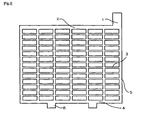
Fig.1 is a pattern diagram of a current collector manufactured by expanding method; and -
Fig.2 is a pattern diagram of current collector manufactured by gravity casting method. -
- 1 Lug part
- 2 Upper frame part
- 3 Grid part
- 4 Lower frame part
- 5 Side frame part
- 6 Foot part
- The rolling method and hot-dip plating method were used to install a surface layer.
- The rolling method is performed in the following method. The composition of an alloy that is a base material of a negative electrode current collector was Pb-0.05%Ca-0.5%Sn was used. The description of Pb-0.05%Ca-0.5%Sn means a lead alloy containing 0.05% of calcium by mass, 0.5% of tin by mass. In this case, it does not mean that the lead does not contain any impurity. The thickness of the base material that is an alloy board is 10mm. On the both surface of the alloy board, a tin sheet, antimony sheet and various alloy sheets with thickness of 0.5mm to be surface layers were layered. They were extended with a mill roller. By this, a rolled sheet with thickness of 1.0mm was manufactured. The thickness of surface layer was approximately 50 microns. Then, the rolled sheet was deployed with a reciprocal type expanding machine so that a surface layer is positioned on a desired position on the negative electrode current collector by adjusting the position of the rolled sheet (expanding method). By this, a negative electrode current collector with a surface layer at a prescribed position was manufactured. Meantime, in the rolling method, the thickness of a surface layer can be adjusted by adjusting the thickness of an alloy to be a base material, the thickness of a sheet to be a surface layer and the thickness of the sheet after rolling.
- The hot-dip plating method is performed in the following procedures. A melting basin containing metals or alloys to be a surface layer was prepared. Specifically, the basin contained alloys such as Sn, Sb, or Pb-50%Sn. An upper frame part and lug part were immersed in the melting basin. A surface layer was generated by the conventional so-called plating method. At this time, a negative electrode current collector may be manufactured in any method. In other words, a negative electrode current collector may be manufactured by gravity casting method or expanding method. The position of the surface layer can be changed by changing the position of the negative electrode current collector to be immersed in the melting basin. The thickness of the surface layer obtained by this method was 0.15mm. If a surface layer covers a part that should not be covered, the surface layer can be removed by polishing the surface of the metal.
- A paste for negative plate was filled into the negative electrode current collector with a surface layer obtained by the method shown above. The paste for negative plate contained lead powder consisting mainly of lead oxide added and mixed with lignin, barium compound, carbon and a given amount of dilute sulfuric acid. An unformed negative plate for 80D26 was obtained by curing a negative electrode current collector filled with a negative plate paste for three days at 35°C.
- Positive electrode current collector manufactured by the expand method was used for positive plate. The positive electrode current collector was made of an alloy of Pb-0.05%Ca-1.0%Sn. A positive plate paste was filled into this positive electrode current collector. The positive plate paste contained lead powder consisting mainly of lead oxide mixed with a given amount of dilute sulfuric acid. An unformed negative plate for 80D26 was obtained by curing a positive electrode current collector filled with a negative plate paste for three days at 35°C.
- A separator made of polyethylene resin manufactured by extrusion method was folded into two. Two sides were sealed mechanically. By this, a sack-like separator with only one side being opening was obtained.
- A negative plate was contained in a sack-like separator. An unformed element is formed by layering in alternate shifts seven positive plates and eight negative plates put in the separator. The unformed element was inserted into a container for 80D26 and the lid wad welded. A dilute sulfuric acid with predefined specific gravity was filled into the container. Then, a container formation (electrical quantity: 280% of theoretical capacity of positive electrode active material, formation time : 18 hours) was performed in a water tank at 25°C. A lead-acid battery (nominal voltage : 12V, rated capacity : 55Ah) with size of 80D26 stipulated in JIS D 5301 was manufactured.
- Lead dioxide powder (4g) was mixed into the manufactured lead-acid battery in advance. By this, moss is likely to adhere to or accumulated on a lug part and upper frame part. In other word, this makes significant difference in cycle life performance of each lead-acid battery.
- A shallow cycle endurance test specified in JIS D 5301 was performed on the lead-acid batteries. Three lead-acid batteries per type were tested. A battery was considered to come to the end of its life when 30 second voltage at discharge of test discharge performed every 480 cycle was less than 7.2V or the voltage when discharging 25A was lower than 9.0V The cycle number of a battery with shortest life among three lead-acid batteries was considered lowest life cycle number.
- Negative electrode current collectors equipped a surface layer by rolling method were manufactured. The parts of a negative electrode current collector to have a surface layer were varied. Various materials were used for manufacturing surface layers of negative electrode current collectors. Further, negative electrode current collectors equipped with a surface layer by the hot-dip plating method were manufactured. Table 1, 2 and 3 show the overview of various negative electrode current collectors manufactured by the method shown above. Lead-acid batteries were manufactured by using these negative electrode current collectors.
- The description of Pb-0.05%Ca-0.5%Sn means a lead alloy containing 0.05% of calcium by weight and 0.5% of tin by weight. In this case, it does not mean that lead contain no impurity. That is the same in other tables.
- The description "O" in the table means that each part of a negative electrode current collector is covered with a surface layer. Meanwhile, the description "X" in the table means that no part of a negative electrode current collector is covered with a surface layer. That is the same in other tables.
Table 1 Negative electrode current collector Surface layer Cycle life performance Manufacturing method Alloy composition Composition Method to form surface layer Lug part Upper frame part Grid part Lower frame part A01 Expanding method Pb-0.05%Ca-0.5%Sn Sn Rolling method O X X X 125 A02 X O X X 130 A03 X X O X 128 A04 X X X O 126 A05 O O X X 352 A06 O X O X 118 A07 X O X O 115 A08 X X O O 105 A09 X O O O 106 A10 O O O O 112 B01 Expanding method Pb-0.05%Ca-0.5%Sn Sn Hot-dip plating method O X X X 125 B02 X O X X 130 B03 X X O X 126 B04 X X X O 127 B05 O O X X 358 B06 O X O X 119 B07 X O X O 114 B08 X X O O 106 B09 X O O O 106 B10 O O O O 111 Table 2 Negative electrode current collector Surface layer Cycle life performance Manufacturing method Alloy composition Composition Method to form surface layer Lug part Upper frame part Grid part Lower frame part C01 Expanding method Pb-0.05%Ca-0.5%Sn Sb Rolling method O X X X 114 C02 X O X X 134 C03 X X O X 128 C04 X X X O 127 C05 O O X X 346 C06 O X O X 116 C07 X O X O 115 C08 X X O O 103 C09 X O O O 105 C10 O O O O 110 D01 Expanding method Pb-0.05%Ca-0.5%Sn Sb Hot-dip plating method O X X X 114 D02 X O X X 134 D03 X X O X 126 D04 X X X O 129 D05 O O X X 340 D06 O X O X 117 D07 X O X O 114 D08 X X O O 104 D09 X O O O 106 D10 O O O O 109 Table 3 Negative electrode current collector Surface layer Cycle life performance Manufacturing method Alloy composition Composition Method to form surface layer Lug part Upper frame part Grid part Lower frame part E01 Expanding method Pb-0.05%Ca-0.5%Sn Pb-5%Sn Rolling method O O X X 238 E02 Pb-8%Sn O O X X 239 E03 Pb-10%Sn O O X X 320 E04 Pb-30%Sn O O X X 322 E05 Pb-50%Sn O O X X 326 E06 Pb-70%Sn O O X X 330 F01 Expanding method Pb-0.05%Ca-0.5%Sn Pb-5%Sb Rolling method O O X X 218 F02 Pb-8%Sb O O X X 219 F03 Pb-10%Sb O O X X 343 F04 Pb-30%Sb O O X X 342 F05 Pb-50%Sb O O X X 348 F06 Pb-70%Sb O O X X 350 G01 Expanding method Pb-0.05%Ca-0.5%Sn Pb-5%Sn-5%Sb Rolling method O O X X 339 G02 Pb-10%Sn-0.05%Ca O O X X 338 G03 Pb-30%Sn- 0.02%Al O O X X 339 G04 Pb-50%Sn-0.1%Bi O O X X 342 G05 Pb-50%Sn- 0.01%Se O O X X 340 G06 Pb-50%Sb-0.1%As O O X X 347 - The experiment (1.6) shown above was performed on manufactured lead-acid batteries. The results are shown below.
- The rightmost columns of table 1, 2 and 3 show the results of cycle life performance of manufactured lead-acid batteries. These results are relative values with the lowest life cycle number of lead-acid battery manufactured by using a negative electrode current collector with completely no surface layer being 100.
- The cycle life performance of lead-acid batteries by using a negative electrode current collector with a surface layer on any parts was better than that of lead-acid batteries by using a negative electrode current collector with no surface layer on any parts. Especially, the cycle life performance of lead-acid batteries manufactured by using a negative electrode current collector with a surface layer on only lug part and upper frame part was quite excellent.
- This tendency was observed both cases in the rolling method and hot-dip plating method to form a surface layer. Additionally, this tendency was observed in both cases that a surface layer was made of tin or antimony.
- The effect of alloy composition of a surface layer on cycle life performance will now be explained. As shown in the rightmost column of table 1, 2 and 3, cycle life performance was better when a surface layer is an alloy of Pb and Sn and the mass ratio of Sn accounts for 10% or more in the whole alloy, an alloy of Pb and Sb and the mass ratio of Sb accounts for 10% or more in the whole alloy, an alloy of Pb, Sn and Sb and the total mass ratio of Sn and Sb accounts for 10% or more in the whole alloy, Sn, or Sb. Additionally, the same effect can be obtained a surface layer contain other elements such as Ca, Al, Bi, Se or As. It is supposed that Sn or Sb contained in a surface layer impact positively.
- After examination, lead-acid batteries were broken up and investigated. In lead-acid batteries manufactured by using a negative electrode current collector with either one of lug part or upper frame covered with no surface layer, moss adhered to the parts with no surface layer. Further, accumulated moss was observed. It is probable that accumulation of moss affects the cycle life performance.
- Meanwhile, the cycle life performance was not improved in lead-acid batteries using a negative electrode current collector with not only lug part and upper frame part but also other parts covered with surface layer. In that case, it is supposed that other factors affected the cycle life performance. The cause will be explained in detail in
embodiment 3. It is expected that materials such as Sn and Sb used as surface layer may function as a factor for reducing electrolyte solution of lead-acid batteries as charge and discharge cycle proceeds. - Negative electrode current collectors were manufactured by gravity casting method. The negative electrode current collector is made of an alloy of Pb-0.05%Ca-0.5%Sn. Then, surface layer was formed on various part of negative electrode current collectors by the hot-dip plating method. Table 4 and 5 show the overview of various negative electrode current collectors as a whole. Lead-acid batteries were manufactured by using these negative electrode current collectors. The methods for manufacturing items other than negative electrode current collector are shown above.
Table 4 Negative electrode current collector Surface layer Cycle life performance Manufacturing method Alloy composition Composition Method to form surface layer Lug part Upper frame part Grid part Lower frame part Side frame part H01 Gravity casting method Pb-0.05%-0.5%Sn Sn Hot-dip plating method O X X X X 126 H02 X O X X X 124 H03 X X O X X 121 H04 X X X O X 120 H05 X X X X O 104 H06 O O X X X 342 H07 O O O X X 129 H08 X X O O O 124 H09 X X O O O 119 H10 X O O O O 118 H11 O O O O O 111 I01 Gravity casting method Pb-0.05%-0.5%Sn Sb Hot-dip plating method O X X X X 123 I02 X O X X X 120 I03 X X O X X 118 I04 X X X O X 118 I05 X X X X O 102 I06 O O X X X 352 I07 O O O X X 127 I08 X X O O O 123 I09 X X O O O 116 I10 X O O O O 117 I11 O O O O O 110 Table 5 Negative electrode current collector Surface layer Cycle life performance Manufacturing method Alloy composition Composition Method to form surface layer Lug part Upper frame part Grid part Lower frame part Side frame part J01 Gravity casting method Pb-0.05%Ca-0.5%Sn Pb-5%Sn Hot-dip plating method O O X X X 210 J02 Pb-8%Sn O O X X X 212 J03 Pb-10%Sn O O X X X 321 J04 Pb-30%Sn O O X X X 329 J05 Pb-50%Sn O O X X X 327 J06 Pb-70%Sn O O X X X 324 K01 Gravity casting method Pb-0.05%Ca-0.5%Sn Pb-5%Sb Hot-dip plating method O O X X X 212 K02 Pb-8%Sb O O X X X 208 K03 Pb-10%Sb O O X X X 328 K04 Pb-30%Sb O O X X X 327 K05 Pb-50%Sb O O X X X 329 K06 Pb-70%Sb O O X X X 331 L01 Gravity casting method Pb-0.05%Ca-0.5%Sn Pb-5%Sn-5%Sb Hot-dip plating method O O X X X 326 L02 Pb-10%Sn- 0.05%Ca O O X X X 325 L03 Pb-30%Sn- 0.02%Al O O X X X 324 L04 Pb-50%Sn-0.01%Bi O O X X X 329 L05 Pb-50%Sn-0.01%Se O O X X X 328 L06 Pb-50%Sb-0.1%As O O X X X 327 - The experiment (1.6) shown above was performed on manufactured lead-acid batteries. The results are shown below.
- The rightmost columns of table 4 and 5 show the results of cycle life performance of manufactured lead-acid batteries. These results are relative values with the lowest life cycle number of lead-acid battery manufactured by using a negative electrode current collector with completely no surface layer being 100.
- In the experiment results, the same tendency as embodiment 1 was observed. The cycle life performance of lead-acid batteries by using a negative electrode current collector with a surface layer only on lug part and upper frame part was very excellent even if the negative electrode current collector manufactured by the gravity casting method. It became clear that cycle life performance was better when a surface layer is an alloy of Pb and Sn and the mass ratio of Sn accounts for 10% or more in the whole alloy, an alloy of Pb and Sb and the mass ratio of Sb accounts for 10% or more in the whole alloy, an alloy of Pb, Sn and Sb and the total mass ratio of Sn and Sb accounts for 10% or more in the whole alloy, Sn, or Sb.
- As shown above, it is apparent that a negative electrode current collector manufactured either by the expanding method or gravity casting method provides the effect of the present invention.
- In some cases, it is difficult to form a surface layer on only the lug part and upper frame part during the production process. Therefore, the effect of parts other than the lug part and upper frame part partially covered with a surface layer on cycle life performance was investigated as follows.
- Negative electrode current collectors with surface layer of Pb-50%Sn or Pb-50%Sb on only upper frame part and lug part by the rolling method were manufactured. The thickness of the surface layer was 50 microns. A surface layer was formed on the parts of this negative electrode current collector other than lug part and upper frame part by the hot-dip plating method.
- Lead-acid batteries were manufactured by using these negative electrode current collectors. The methods for manufacturing items other than negative electrode current collector are shown above.
Table 6 Negative electrode current collector Surface layer Cycle life performance Amount of reduced liquid Manufacturing method Alloy composition Composi tion Method to form surface layer Lug part Upper frame part The ratio of areas covered with the second surface layer to the areas other than the lug part and upper frame part (%) M01 Gravity casting method Pb-0.05%Ca-0.5%Sn Pb-50%Sn Hot-dip plating method O O 0 320 101 M02 O O 10 317 105 M03 O O 15 314 106 M04 O O 20 313 107 M05 O O 25 150 129 M06 O O 30 137 137 N01 Gravity casting method Pb-0.05%Ca-0.5%Sn Hot-dip plating method O O 0 320 102 N02 O O 10 320 106 N03 Pb- O O 15 325 105 N04 50%Sb O O 20 312 109 N05 O O 25 140 134 N06 O O 30 102 149 001 Gravity casting method Pb-0.05%Ca-0.5%Sn Pb-50%Sn Rolling method O O 0 324 101 002 O O 10 320 104 003 O O 15 319 105 004 O O 20 317 105 005 O O 25 136 137 006 O O 30 132 141 P01 Expandng method Pb-0.05%Ca-0.5%Sn Pb-50%Sb Hot-dip plating method O O 0 328 102 P02 O O 10 326 105 P03 O O 15 315 105 P04 O O 20 312 107 P05 O O 25 135 135 P06 O O 30 128 140 - The experiment (1.6) shown above was performed. The results are shown below.
- The second rightmost column of table 6 shows the results of cycle life performance of manufactured lead-acid batteries. These results are relative values with the lowest life cycle number of lead-acid battery manufactured by using a negative electrode current collector with completely no surface layer being 100.
- If the ratio of the area other than upper frame part and lug part covered with a surface layer (the second layer) to the parts other than upper frame part and lug part is 20% or less, the cycle life performance was almost the same as the case where a surface layer covered only lug part and upper frame part and excellent. This tendency was the same for the composition of the surface layer was Pb-50%Sn or Pb-50%Sb. However, if the ratio of the area other than upper frame part and lug part covered with a surface layer (the second layer) to the parts other than upper frame part and lug part is more than 20%, the cycle life performance was lower than the case where a surface layer covered only lug part and upper frame part.
- As a result of breaking up lead-acid batteries after the experiment, electrolyte solution was reduced in batteries with poor cycle life performance. It is supposed that reduction of electrolyte solution according to charge and discharge cycle exerts a harmful influence on the cycle life performance. The larger the ratio of surface area other than upper frame part and lug part covered with a surface layer to the surface area other than upper frame part and lug part got, the more electrolyte solution was reduced. The reduction of electrolyte was calculated from differences in mass of lead-acid batteries before and after the cycle life test. These results are relative values with the lowest life cycle number of lead-acid battery manufactured by using a negative electrode current collector with completely no surface layer being 100 and shown in the rightmost columns of table 6.
- As a result of embodiment 1 to 3, it has become apparent that (i) excellent cycle life performance is obtained if the part other than the lug part and upper frame part has no surface layer, and (ii) the effect for improving cycle life performance is not reduced if the ratio of area covered with the second surface layer to the part other than lug part and upper frame part is 20% or less even when the part other than lug part and upper frame part have a surface layer (the second surface layer).
- The present application is based on the Japanese Patent Application (No.
2004-324343 - As shown above, according to the present invention, the upper frame part and lug part have a surface layer with a certain composition in a negative electrode current collector for a lead-acid battery having a grid part, upper frame part, and lug part. A lead-acid battery shows excellent cycle life performance by manufacturing the lead-acid battery using this negative electrode current collector. Lead-acid batteries are used in various industries. The present invention, therefore, is industrially applicable, and its industrial advantage is extremely large.
Claims (3)
- A negative electrode current collector for a lead-acid battery comprising a grid part, an upper frame part, and a lug part, wherein;
said upper frame part and said lug part have a surface layer,
said surface layer is an alloy of Pb and Sn and the mass ratio of Sn accounts for 10% or more in the whole alloy, an alloy of Pb and Sb and the mass ratio of Sb accounts for 10% or more in the whole alloy, an alloy of Pb, Sn and Sb and the total mass ratio of Sn and Sb accounts for 10% or more in the whole alloy, Sn, or Sb. - A negative electrode current collector for a lead-acid battery according to claim 1, wherein;
a part other than said upper frame part and said lug part has a surface layer,
a ratio of the area covered with the surface layer to a surface area of said part other than said upper frame part and said lug part is 20% or less. - A lead-acid battery comprising the negative electrode current collector for a lead-acid battery according to claim 1 or 2.
Applications Claiming Priority (2)
| Application Number | Priority Date | Filing Date | Title |
|---|---|---|---|
| JP2004324343 | 2004-11-08 | ||
| PCT/JP2005/020422 WO2006049295A1 (en) | 2004-11-08 | 2005-11-08 | Negative electrode current collector for lead storage battery and lead storage battery including the same |
Publications (3)
| Publication Number | Publication Date |
|---|---|
| EP1816693A1 EP1816693A1 (en) | 2007-08-08 |
| EP1816693A4 EP1816693A4 (en) | 2009-11-04 |
| EP1816693B1 true EP1816693B1 (en) | 2011-03-16 |
Family
ID=36319291
Family Applications (1)
| Application Number | Title | Priority Date | Filing Date |
|---|---|---|---|
| EP05806142A Ceased EP1816693B1 (en) | 2004-11-08 | 2005-11-08 | Negative electrode current collector for lead storage battery and lead storage battery including the same |
Country Status (4)
| Country | Link |
|---|---|
| EP (1) | EP1816693B1 (en) |
| CN (1) | CN101048900B (en) |
| DE (1) | DE602005026977D1 (en) |
| WO (1) | WO2006049295A1 (en) |
Families Citing this family (8)
| Publication number | Priority date | Publication date | Assignee | Title |
|---|---|---|---|---|
| EP2280443B1 (en) * | 2008-05-20 | 2014-03-12 | GS Yuasa International Ltd. | Lead storage battery and process for producing the lead storage battery |
| JP5522444B2 (en) * | 2008-09-22 | 2014-06-18 | 株式会社Gsユアサ | Lead acid battery |
| JPWO2012153464A1 (en) * | 2011-05-12 | 2014-07-31 | パナソニック株式会社 | Negative electrode for lead acid battery and lead acid battery |
| EP3306715B1 (en) * | 2015-05-29 | 2023-01-11 | GS Yuasa International Ltd. | Lead-acid battery and method for producing lead-acid battery |
| WO2017098666A1 (en) * | 2015-12-11 | 2017-06-15 | 日立化成株式会社 | Lead storage battery |
| WO2021049036A1 (en) * | 2019-09-13 | 2021-03-18 | 昭和電工マテリアルズ株式会社 | Lead storage battery |
| WO2021049037A1 (en) * | 2019-09-13 | 2021-03-18 | 昭和電工マテリアルズ株式会社 | Lead-acid battery |
| CN114614020B (en) * | 2022-03-21 | 2023-05-09 | 合肥国轩高科动力能源有限公司 | A kind of preparation method of composite current collector |
Family Cites Families (12)
| Publication number | Priority date | Publication date | Assignee | Title |
|---|---|---|---|---|
| JPS58225568A (en) | 1982-06-23 | 1983-12-27 | Shin Kobe Electric Mach Co Ltd | Sheet metal for lead battery electrode lattice and its production method |
| JPS5983350A (en) * | 1982-11-05 | 1984-05-14 | Matsushita Electric Ind Co Ltd | Grid for lead-acid battery |
| JPS63237354A (en) | 1987-03-26 | 1988-10-03 | Matsushita Electric Ind Co Ltd | Grid for lead acid batteries |
| JPS63237358A (en) * | 1987-03-26 | 1988-10-03 | Matsushita Electric Ind Co Ltd | Method for manufacturing grids for lead-acid batteries |
| JPH03105861A (en) * | 1989-09-19 | 1991-05-02 | Japan Storage Battery Co Ltd | Clad type lead-acid battery |
| JPH03205762A (en) * | 1990-01-06 | 1991-09-09 | Japan Storage Battery Co Ltd | Manufacturing apparatus for lattice for lead-acid battery |
| JPH0817461A (en) | 1994-06-29 | 1996-01-19 | Matsushita Electric Ind Co Ltd | Lead acid battery |
| JPH0817460A (en) | 1994-06-29 | 1996-01-19 | Matsushita Electric Ind Co Ltd | Lead acid battery |
| JPH08185853A (en) | 1994-12-27 | 1996-07-16 | Matsushita Electric Ind Co Ltd | Lead acid battery |
| JPH08236101A (en) | 1995-02-24 | 1996-09-13 | Matsushita Electric Ind Co Ltd | Lead acid battery |
| JPH11329399A (en) | 1998-05-22 | 1999-11-30 | Matsushita Electric Ind Co Ltd | Lead storage battery |
| US6953641B2 (en) * | 2001-01-05 | 2005-10-11 | Johnson Controls Technology Company | Battery grid |
-
2005
- 2005-11-08 CN CN2005800367931A patent/CN101048900B/en not_active Expired - Fee Related
- 2005-11-08 EP EP05806142A patent/EP1816693B1/en not_active Ceased
- 2005-11-08 WO PCT/JP2005/020422 patent/WO2006049295A1/en not_active Ceased
- 2005-11-08 DE DE602005026977T patent/DE602005026977D1/en not_active Expired - Lifetime
Also Published As
| Publication number | Publication date |
|---|---|
| WO2006049295A1 (en) | 2006-05-11 |
| CN101048900A (en) | 2007-10-03 |
| EP1816693A4 (en) | 2009-11-04 |
| EP1816693A1 (en) | 2007-08-08 |
| DE602005026977D1 (en) | 2011-04-28 |
| CN101048900B (en) | 2010-06-16 |
Similar Documents
| Publication | Publication Date | Title |
|---|---|---|
| JP5477288B2 (en) | Lead-acid battery and method for manufacturing the same | |
| JP5522444B2 (en) | Lead acid battery | |
| US5120620A (en) | Binary lead-tin alloy substrate for lead-acid electrochemical cells | |
| EP1816693A1 (en) | Negative electrode current collector for lead storage battery and lead storage battery including the same | |
| MXPA05000736A (en) | Lead-based alloy for lead-acid battery grid. | |
| JP7296016B2 (en) | Lead alloy foil, positive electrode for lead-acid battery, lead-acid battery, and power storage system | |
| US6620551B1 (en) | Positive plate current collector for lead storage battery and lead storage battery comprising the same | |
| EP1717896A1 (en) | Lead acid battery | |
| US20080131774A1 (en) | Negative Electrode Current Collector for Lead Storage Battery and Lead Storage Battery Including the Same | |
| JP5061451B2 (en) | Anode current collector for lead acid battery | |
| JPWO2001004976A1 (en) | Positive electrode current collector for lead-acid battery and lead-acid battery using the same | |
| EP1737062A1 (en) | Lead storage battery | |
| JPH10284085A (en) | Grid for lead-acid battery | |
| JP4292666B2 (en) | Sealed lead acid battery | |
| US20050037264A1 (en) | Lead battery | |
| JP2023079571A (en) | liquid lead acid battery | |
| JPH11111274A (en) | Lead-acid battery | |
| JP2001202967A (en) | Lead storage battery and method of manufacturing the same | |
| JP5145644B2 (en) | Lead acid battery | |
| EP0504815A1 (en) | Sealed lead-acid secondary battery | |
| JPH10270030A (en) | Sealed lead-acid battery | |
| JP2004311357A (en) | Lead storage battery | |
| JPH10172542A (en) | Sealed lead-acid battery | |
| JP2009193835A (en) | Lead battery and method of manufacturing lead battery | |
| JPH10302784A (en) | Manufacturing method of paste type positive electrode plate |
Legal Events
| Date | Code | Title | Description |
|---|---|---|---|
| PUAI | Public reference made under article 153(3) epc to a published international application that has entered the european phase |
Free format text: ORIGINAL CODE: 0009012 |
|
| 17P | Request for examination filed |
Effective date: 20070503 |
|
| AK | Designated contracting states |
Kind code of ref document: A1 Designated state(s): DE FR |
|
| DAX | Request for extension of the european patent (deleted) | ||
| RBV | Designated contracting states (corrected) |
Designated state(s): DE FR |
|
| A4 | Supplementary search report drawn up and despatched |
Effective date: 20091007 |
|
| GRAP | Despatch of communication of intention to grant a patent |
Free format text: ORIGINAL CODE: EPIDOSNIGR1 |
|
| GRAS | Grant fee paid |
Free format text: ORIGINAL CODE: EPIDOSNIGR3 |
|
| GRAA | (expected) grant |
Free format text: ORIGINAL CODE: 0009210 |
|
| RAP1 | Party data changed (applicant data changed or rights of an application transferred) |
Owner name: GS YUASA INTERNATIONAL LTD. |
|
| AK | Designated contracting states |
Kind code of ref document: B1 Designated state(s): DE FR |
|
| REF | Corresponds to: |
Ref document number: 602005026977 Country of ref document: DE Date of ref document: 20110428 Kind code of ref document: P |
|
| REG | Reference to a national code |
Ref country code: DE Ref legal event code: R096 Ref document number: 602005026977 Country of ref document: DE Effective date: 20110428 |
|
| PLBE | No opposition filed within time limit |
Free format text: ORIGINAL CODE: 0009261 |
|
| STAA | Information on the status of an ep patent application or granted ep patent |
Free format text: STATUS: NO OPPOSITION FILED WITHIN TIME LIMIT |
|
| 26N | No opposition filed |
Effective date: 20111219 |
|
| REG | Reference to a national code |
Ref country code: DE Ref legal event code: R097 Ref document number: 602005026977 Country of ref document: DE Effective date: 20111219 |
|
| REG | Reference to a national code |
Ref country code: FR Ref legal event code: PLFP Year of fee payment: 11 |
|
| REG | Reference to a national code |
Ref country code: FR Ref legal event code: PLFP Year of fee payment: 12 |
|
| REG | Reference to a national code |
Ref country code: FR Ref legal event code: PLFP Year of fee payment: 13 |
|
| REG | Reference to a national code |
Ref country code: FR Ref legal event code: PLFP Year of fee payment: 14 |
|
| PGFP | Annual fee paid to national office [announced via postgrant information from national office to epo] |
Ref country code: FR Payment date: 20221010 Year of fee payment: 18 |
|
| PGFP | Annual fee paid to national office [announced via postgrant information from national office to epo] |
Ref country code: DE Payment date: 20220621 Year of fee payment: 18 |
|
| P01 | Opt-out of the competence of the unified patent court (upc) registered |
Effective date: 20230522 |
|
| REG | Reference to a national code |
Ref country code: DE Ref legal event code: R119 Ref document number: 602005026977 Country of ref document: DE |
|
| PG25 | Lapsed in a contracting state [announced via postgrant information from national office to epo] |
Ref country code: DE Free format text: LAPSE BECAUSE OF NON-PAYMENT OF DUE FEES Effective date: 20240601 |
|
| PG25 | Lapsed in a contracting state [announced via postgrant information from national office to epo] |
Ref country code: FR Free format text: LAPSE BECAUSE OF NON-PAYMENT OF DUE FEES Effective date: 20231130 |
|
| PG25 | Lapsed in a contracting state [announced via postgrant information from national office to epo] |
Ref country code: FR Free format text: LAPSE BECAUSE OF NON-PAYMENT OF DUE FEES Effective date: 20231130 Ref country code: DE Free format text: LAPSE BECAUSE OF NON-PAYMENT OF DUE FEES Effective date: 20240601 |