EP1816651A2 - Structure intended to be connected to a referential through the intermediary of external connection means and including an apparatus permitting the vibrations thereof to be reduced - Google Patents
Structure intended to be connected to a referential through the intermediary of external connection means and including an apparatus permitting the vibrations thereof to be reduced Download PDFInfo
- Publication number
- EP1816651A2 EP1816651A2 EP07352001A EP07352001A EP1816651A2 EP 1816651 A2 EP1816651 A2 EP 1816651A2 EP 07352001 A EP07352001 A EP 07352001A EP 07352001 A EP07352001 A EP 07352001A EP 1816651 A2 EP1816651 A2 EP 1816651A2
- Authority
- EP
- European Patent Office
- Prior art keywords
- wall
- rigid support
- support means
- resilient shock
- contact
- Prior art date
- Legal status (The legal status is an assumption and is not a legal conclusion. Google has not performed a legal analysis and makes no representation as to the accuracy of the status listed.)
- Granted
Links
- 230000000694 effects Effects 0.000 claims abstract description 8
- 230000006835 compression Effects 0.000 claims description 18
- 238000007906 compression Methods 0.000 claims description 18
- 238000006073 displacement reaction Methods 0.000 description 12
- 239000000463 material Substances 0.000 description 7
- 229920000642 polymer Polymers 0.000 description 5
- 206010043268 Tension Diseases 0.000 description 4
- 238000001816 cooling Methods 0.000 description 3
- 239000012858 resilient material Substances 0.000 description 3
- 230000035939 shock Effects 0.000 description 3
- 230000002238 attenuated effect Effects 0.000 description 2
- 238000003466 welding Methods 0.000 description 2
- 239000006096 absorbing agent Substances 0.000 description 1
- 238000010521 absorption reaction Methods 0.000 description 1
- 238000004026 adhesive bonding Methods 0.000 description 1
- 239000000470 constituent Substances 0.000 description 1
- 238000010276 construction Methods 0.000 description 1
- 238000002788 crimping Methods 0.000 description 1
- 238000001914 filtration Methods 0.000 description 1
- 238000012423 maintenance Methods 0.000 description 1
- 239000007769 metal material Substances 0.000 description 1
- 239000004033 plastic Substances 0.000 description 1
- 229920003023 plastic Polymers 0.000 description 1
- 230000000750 progressive effect Effects 0.000 description 1
- 239000002470 thermal conductor Substances 0.000 description 1
Images


Classifications
-
- F—MECHANICAL ENGINEERING; LIGHTING; HEATING; WEAPONS; BLASTING
- F16—ENGINEERING ELEMENTS AND UNITS; GENERAL MEASURES FOR PRODUCING AND MAINTAINING EFFECTIVE FUNCTIONING OF MACHINES OR INSTALLATIONS; THERMAL INSULATION IN GENERAL
- F16F—SPRINGS; SHOCK-ABSORBERS; MEANS FOR DAMPING VIBRATION
- F16F15/00—Suppression of vibrations in systems; Means or arrangements for avoiding or reducing out-of-balance forces, e.g. due to motion
- F16F15/02—Suppression of vibrations of non-rotating, e.g. reciprocating systems; Suppression of vibrations of rotating systems by use of members not moving with the rotating systems
- F16F15/04—Suppression of vibrations of non-rotating, e.g. reciprocating systems; Suppression of vibrations of rotating systems by use of members not moving with the rotating systems using elastic means
- F16F15/08—Suppression of vibrations of non-rotating, e.g. reciprocating systems; Suppression of vibrations of rotating systems by use of members not moving with the rotating systems using elastic means with rubber springs ; with springs made of rubber and metal
Definitions
- the present invention relates to the field of structures intended to be connected to a referential through the intermediary of external connection means, and of which structure it is sought to reduce the vibrations, such as, for example, to limit the resonance of a structure, more especially but not exclusively a structure of the chassis type comprising associated electronic equipment, for example electronic cards or modules.
- the referential may be fixed or displaceable relative to the ground.
- the means for externally connecting the structure to the referential may include rigid connection means or resilient connection means or viscoelastic connection means.
- the electronic modules incorporated in a structure of the chassis type, are generally subject, on the one hand, to the vibrations generated by the vehicle on which they are mounted, for example a boat, an aeroplane, a vehicle with wheels or a vehicle with caterpillar tracks, and, on the other hand, to the resonances of the structure itself which amplifies the vibratory level at the various resonance frequencies of the elements which form the structure or parts thereof.
- Prior art discloses means for attenuating the vibratory levels at the inlet of the structure, by using shock absorbers outside the structure and connecting this structure, for example, to the vehicle which carries it, but that has no effect on the vibratory level caused by resonances of the structure itself, or of the elements which form it, or of the parts thereof.
- One solution consists of using a resilient material of the polymer type associated, by gluing, with a precise location of the structure in order to attenuate the resonance thereof.
- the material of the polymer type converts the mechanical energy, induced by the vibrations, into heat by displacing the molecules inside the material.
- Such a solution has the disadvantage of necessitating a large amount of material of the polymer type in order to obtain a significant reduction in the vibration amplitude of the structure onto which it is glued.
- the effectiveness of such a solution is generally limited to high frequencies.
- the invention consists of a structure intended to be connected to a referential through the intermediary of external connection means, characterised in that it includes at least one apparatus which differs from said external connection means, said apparatus permitting the vibrations of said structure to be reduced, and comprising:
- the structure according to the invention thus incorporates an apparatus including rigid support means connected to the structure by a specific first connection, and equally by a second resilient connection, the two connections combined permitting a stress, for example an initial stress, to be exerted upon the resilient shock-absorbing means and thus to absorb easily the vibrations of the wall on which the apparatus acts, and, by extension, on the structure including this wall.
- a stress for example an initial stress
- the structure vibrates, the specific distance which exists between the support means and the wall, between which are situated the stressed, preferably compressed, resilient shock-absorbing means, is modified locally in the contact area, causing the extension and the compression of the resilient shock-absorbing means, and the progressive shock-absorption of the vibration by transferring the energy, engendered by the vibration, towards the resilient shock-absorbing means in the form of heat.
- the first connection must permit a displacement of the wall relative to the support means by the vibratory effect, more especially at the resonance frequency of the wall, so as to allow a movement of the resilient shock-absorbing means.
- the amount of stress on the resilient shock-absorbing means preferably an initial stress, for given characteristics of resilient shock-absorbing means, permits action on the vibration frequency which will be effectively attenuated, advantageously corresponding to the resonance frequency of the wall or of the structure.
- the resilient shock-absorbing means may all be resilient means, for example springs which include, by their very nature, the capacity to absorb the shocks of resilience.
- said first connection means are formed by complete rigid connection means between said rigid support means and said structure, said resilient shock-absorbing means being disposed in a stressed state in said free space, established between the support means and said first wall, between two surfaces respectively facing the rigid support means and said first wall.
- This feature proposes a rigid fixing of the support means, which could possibly be controllable so as to permit a control of the stress or initial stress of the resilient shock-absorbing means.
- the complete rigid connection means must permit a possibility for deforming the wall relative to the rigid support means.
- connection types for example a partial rigid connection by a simple support as opposed to a complete rigid connection of the embedding type, giving various deformations to the wall relative to the rigid support means, to the extent where a relative displacement, between these elements, perpendicular to the surface of the wall, is possible so as to displace the resilient shock-absorbing means.
- the person skilled in the art by using this knowledge, will be able to adapt the best choice of connection relative to a given structure and to the desired results for reducing the vibrations.
- the structure according to the invention includes an intermediate supporting plate disposed, in said free space, between said resilient shock-absorbing means and said first wall, said resilient shock-absorbing means being disposed in an initially stressed state in said free space.
- the intermediate supporting plate permits the compression force, exerted by the resilient shock-absorbing means, to be distributed uniformly over a given surface, that of the supporting plate, when said resilient shock-absorbing means are in the form of a plurality of compression springs, for example.
- the structure according to the invention includes complete connection means between said intermediate supporting plate and said resilient shock-absorbing means and between said intermediate supporting plate and said first wall.
- a first face of said rigid support means is in contact with said resilient shock-absorbing means, and a second face of said rigid support means, opposite the first face, is a surface free of any contact with an element of the structure or connected thereto.
- This feature allows the apparatus, which permits the vibrations of said structure to be reduced, to be mounted on a wall of the latter, free of any contact with elements fitted in the structure or with other elements of the structure.
- a first face of said support means is in contact with said resilient shock-absorbing means, and a second face of said rigid support means, opposite the first face, is connected, by contact, to a second wall of said structure or an element associated with the latter, so as to become part of said first connection means between the rigid support means and the structure.
- This feature permits the specific first connection to be established via a second wall of the structure or via an element associated therewith, in particular an electronic module or the like of the contact connection type, and thus also permits, in this latter case, in addition, the apparatus, which permits the vibrations of the structure to be reduced, to assume a function of thermal dissipation or of transferring the heat generated by the electronic module towards the structure, on condition that the thermal conduction is then ensured by said apparatus between the electronic module and the structure.
- connection by contact is an obstacle type of connection in one direction perpendicular to the wall, in which direction the resilient shock-absorbing means are displaced; in a perpendicular direction thereto, that is to say in the plane of the wall, the first connection can include a degree of freedom, for example in translation in the case of a connection by contact, since the resilient shock-absorbing means are not intended to operate in such a direction so as to reduce the vibrations of the wall.
- said resilient shock-absorbing means include a plurality of compression springs, a first end of said compression springs being in contact with said intermediate supporting plate, and a second end of said compression springs, opposite the first end, being in contact with said rigid support means.
- the plurality of compression springs permit the vibrations to be attenuated or filtered at lower frequencies than the resilient material of the polymer type of prior art.
- the tenseness of the apparatus permitting the vibrations of the structure to be reduced may also be modulated with the number of springs chosen. It is equally possible to combine, on one and the same apparatus, springs of different degrees of tenseness.
- the solution of the compression spring permits a wider choice of different degrees of tenseness to be available than the solution of the resilient material of the polymer type of prior art.
- the resilient shock-absorbing means are connected to the rigid support means and to the intermediate supporting plate by a complete connection, so that the rigid support means can assume at least two positions, a first position, called the inoperative position, in which the resilient shock-absorbing means are relaxed, and a second position, called the operative position, in which the resilient shock-absorbing means are in an initially stressed state when they are in contact with the second wall of said structure or an element associated with the latter.
- This feature proposes a particular configuration of the apparatus, permitting the vibrations of the structure to be reduced, which configuration aims to facilitate the mounting of said apparatus in the structure, in contact with the second wall of said structure or an element associated with the latter.
- the resilient shock-absorbing means include a plurality of flexible strips.
- the resilient strips of the plurality of strips each assume substantially an S- or Z-shaped form, a first branch of the S or of the Z being fixed to the rigid support means, and the second branch of the S or of the Z being fixed to the intermediate supporting plate or to said wall.
- the flexible strips of said plurality of strips each assume a symmetrical form relative to a plane parallel to the intermediate supporting plate.
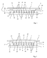
- Figure 1 is a side elevational view of a first embodiment of a partial structure according to the invention, which includes an apparatus permitting the vibrations of the structure to be reduced, at rest.
- Figure 2 is a side elevational view of the example in Figure 1, in action.
- Figure 3 is a side elevational view of a second embodiment of a partial structure according to the invention, which includes an apparatus permitting the vibrations of the structure to be reduced, at rest, in a first position prior to being mounted.
- Figure 4 illustrates the example in Figure 3 in its position after being mounted, at rest.
- Figure 5 is a side elevational view of a third embodiment of a partial structure according to the invention, including an apparatus permitting the vibrations of the structure to be reduced, at rest.
- the structure 3 includes an apparatus 1 which permits the vibrations of this structure 3 to be reduced, and comprises:
- the structure 3 may be any structure of the chassis, on-board, portable or fixed type, which defines an enclosure surrounding an electronic unit composed, for example, of electronic modules or cards (not illustrated), assuming for example a polyhedral, generally parallelepiped, form which includes a plurality of flat, horizontal, vertical, and/or inclined walls, one of these walls, 15, being illustrated in Figures 1 and 2, on which the apparatus 1 is fixed.
- the wall 15 of the structure 3 is, for example, a vertical wall of the structure, but the apparatus could be mounted on other walls, horizontal walls or different walls of the structure, alternatively or additionally, by using the desired results of vibratory weakness.
- the apparatus 1 illustrated will advantageously be secured in an area of the wall 15 which generates the greatest vibration amplitude at the resonance frequency of the wall, which may, for example, be situated in the area which is the furthest remote from the edges of the wall 15, which are connected to other walls of the structure, or in an accessible area close to said structure, depending on the space available in the structure.
- the apparatus 1 will be placed inside the structure in order to be protected from shocks, more especially caused by the walls.
- One apparatus is necessary for one wall, but several apparatuses 1 could be used on one and the same wall, depending on the dimensions thereof.
- the effectiveness of the apparatus 1 extends to the other connected walls (not illustrated) of the structure, due to the diminution in the amplitude of the vibrations of the wall 15 on which it is fixed, and thus extends to all of the structure 3.
- the structure 3 is intended to be connected to a fixed or displaceable referential, for example the ground or a vehicle intended to move relative thereto, through the intermediary of external connection means, which differ from the apparatus 1.
- These means for externally connecting the structure 3 to the referential may include any known means, such as, for example, rigid connection means or resilient connection means or viscoelastic connection means or simply a connection by obstacle of the simple supporting type.
- the rigid support means 4 will advantageously assume the form of a plate 18, as illustrated in Figures 1 and 2, which is rigid in that it does not have to become deformed in an identical manner to the wall 15, in order that the resilient shock-absorbing means 6, being supported on a face 19 of the plate 18, can themselves become deformed. It is necessary to select a plate, the resonance frequency of which is different from that of the wall in the structure 3, or of which the deformations at this resonance frequency are different.
- the surface of the plate 18 will be defined according to the extent of the surface occupied by the resilient shock-absorbing means 6 and the space available, as will be explained hereinafter, and will be able to assume a rectangular form, for example.
- the constituent material of the plate 4 may be any material which is sufficiently rigid to fulfil the function explained above, for example a plastics material, a metallic material or other material.
- the first connection means 2 are formed by complete rigid connection means between the rigid support means 4 and the structure 3, the resilient shock-absorbing means 6 being advantageously disposed in an initially stressed state in the free space 14, established between the support means 4 and the first wall 15, between two surfaces 19, 20 respectively facing the rigid support means 4 and the first wall 15.
- the complete rigid connection means between the rigid support means 4 and the structure 3 may, for example, assume the form of a connection by columns 21, screwed into the plate 18 and into the wall 15. It is necessary to note that the deformation of the wall portion 15 facing the plate 18 can be modified provided that the first connection means 2 are of the embedding type, or of the simple supporting type which can allow a displacement of the rotary type for the wall 15 about the foot of the column 21, said rotary displacement being induced by the deformation of the wall subsequent to the vibrations to which it is subject.
- the apparatus 1, illustrated in Figures 1 and 2 may include an intermediate supporting plate 5 disposed, in the free space 14, between the resilient shock-absorbing means 6 and the first wall 15, serving to support the resilient shock-absorbing means 6.
- the apparatus 1 includes, in this case for example, complete connection means (not illustrated) between the intermediate supporting plate 5 and the resilient shock-absorbing means 6, as we shall see hereinafter, and between the intermediate supporting plate 5 and the first wall 15, for example by screws or the like.
- the intermediate supporting plate 5 is made totally integral with the wall 15.
- intermediate supporting plate 5 is optional; it permits the forces, exerted by the resilient shock-absorbing means, to be distributed uniformly over the surface of the plate, and can permit the initial stress of the resilient shock-absorbing means 6 to be controlled according to its thickness, for a given height of column 21.
- a first face 19 of the rigid support means 4 is in contact with the resilient shock-absorbing means 6, and a second face 22 of the rigid support means 4, opposite the first face 19, is a surface free of any contact with an element of the structure or connected thereto, as illustrated.
- the apparatus 1, illustrated in Figures 1 and 2 necessitates, in order to be fixed to the wall 15, a free surface on the wall 15 on the inside of the structure, substantially equal to the surface of the rigid plate 18, and a free space available from this surface 20 and towards the interior of the structure 3 equivalent to the thickness of the plate 18 plus the height of the columns 21, itself being equal to the height of the resilient initially stressed shock-absorbing means 6 plus the thickness of the intermediate supporting plate 5 if necessary.
- the resilient shock-absorbing means 6 advantageously include a plurality of compression springs 23, a first end 24 of the compression springs 23 being in contact, in the example illustrated, with the intermediate supporting plate 5, and a second end 25 of the compression springs, opposite the first end 24, being in contact with the rigid support means 4, namely the rigid plate 18, as illustrated in Figures 1 and 2.
- the springs 23 may be of the helical spring type, the compression axis of which will be disposed perpendicular to the wall 15, as illustrated in Figure 1.
- the springs 23 may either be kept simply tensioned, during the mounting, between the plate 18 and the intermediate plate 5, the ends being guided into respective appropriate receiving means in these plates, or fixed by their ends, for example by welding, crimping or the like between these same plates, or possibly on a single plate thereof, the plate 18 if the intermediate plate 5 is absent, the springs 23 then being placed in simple direct support on the wall 15 (not illustrated).
- the compression springs may be metallic, for example, and be identical or different depending on the desired effect for attenuating or for filtering the vibrations.
- FIGs 3 and 4 is similar to the example in Figures 1 and 2, and differs essentially therefrom in that a first face 19 of the rigid support means 4 is in contact with the resilient shock-absorbing means 6, and a second face 22 of the rigid support means 4, opposite the first face 19, is connected, by contact, to a second wall (not illustrated) of the structure 3, or to an element 30, associated with the latter as illustrated in Figure 4, so as to form part of the first connection means 2 between the rigid support means 4 and the structure 3.
- the elements of the apparatus 1 according to the invention have the same function or functions as those of the first example according to Figures 1 and 2, they have the same reference numeral. For these functionally identical elements, the reader will be referred to the description of the first embodiment according to Figures 1 and 2.
- connection 2 between the rigid support means 4 and the structure 3 is not a complete rigid connection, directly on the wall 15 of the structure 3 as in the first example according to Figures 1 and 2, but is a connection by obstacle and by contact with an electronic module or card 30 for example, itself connected to the structure 3 by means of a complete rigid connection (not illustrated) once mounted in the structure 3, this being achieved in known manner, for example, in a slide (not illustrated) provided for this purpose.
- the electronic module 30 which has a specific fixed position relative to the structure, that is to say relative to the wall 15, permits a specific distance to be established between the rigid support means 4 and the first wall 15, which is capable of being modified by the effect of a vibration of this wall 15.
- connection 2 by obstacle which permits the electronic module 30 to be established between the support means 4 and the structure 3, must be achieved in a perpendicular direction 31 to the wall 15, the vibrations of which it is desirable to attenuate, in order for the springs 23 to be able to be compressed or stretched, in this direction 3, according to the vibratory deformation of the wall 15.
- the connection 2 by contact can permit one or more degrees of freedom in a parallel plane to the wall 15 to the extent where the springs 23 do not operate in this plane.
- the resilient shock-absorbing means 6 are connected to the rigid support means 4 and to the intermediate supporting plate 5 by a complete connection 26, for example by welding as illustrated, so that the rigid support means 4 can assume at least two positions, a first position 7, called the inoperative position illustrated in Figure 3, in which the resilient shock-absorbing means 6 are relaxed, and a second position 8, called the operative position illustrated in Figure 4, in which the shock-absorbing means 6 are in the advantageously initially stressed state when they are in contact with the element 30 associated with the structure 3.
- the intermediate supporting plate 5 is advantageously secured to the wall 15 according to any known means, for example by screws, in order to permit the apparatus 1 to be kept in its relaxed position on the wall 15, until the mounting of the electronic module or card 30 which will ensure the initial stress of the springs 23 by displacement of the plate 18 towards the wall 15, thereby entraining the compression of the springs 23.
- the springs 23 will each advantageously assume a form of a flexible strip 9, for example substantially an S-shaped form (as illustrated in Figures 3 and 4) or a Z-shaped form (not illustrated), a first terminal branch 11 of the S or of the Z being fixed to the rigid support means 4, the second terminal branch 12 of the S or of the Z being fixed to the intermediate supporting plate 5, as illustrated in Figures 3 and 4.
- the resilient shock-absorbing means 6 are preferably disposed so as to permit a resilient displacement in translation of the support plate 4 relative to the intermediate supporting plate 5, the latter being parallel or substantially parallel. This is because the electronic modules or cards in an enclosure inside the structure are generally placed, once mounted, in a manner parallel to some of the walls of the chassis and perpendicular to other walls.
- an electronic module or card 30 is introduced, for example, by sliding into its receiving means formed in the structure (not illustrated), for example parallel to the wall 15, the vibrations of which it is desirable to reduce.
- the resilient shock-absorbing means 6 will advantageously be disposed so that a thrust effort parallel to the collector plate 5, as illustrated by the arrow 32 in Figure 3, and thereupon, entrains a displacement of the plate 18 towards the intermediate supporting plate 5 whilst compressing the flexible strips 9, as illustrated by the arrow 33 in Figure 3 and as will be explained in more detail hereinafter.
- the support plate 18 may advantageously include a chamfered edge of attack (not illustrated) intended to facilitate the commencement of the sliding of the electronic module or card 30 thereon, during which the resilient means 6 are compressed.
- the arrow 31 shows the direction of the force exerted by the electronic module or card 30 on the apparatus 1, perpendicular to the plates 5 and 18, and to the wall 15 of the structure 3.
- the form of the flexible strips 9 will advantageously be defined in dependence on the way in which the electronic modules or cards are mounted in the structure 3, with which module or card the apparatus 1 is intended to make contact in order to ensure the connection 2 by obstacle and contact.
- the flexible strips 9 of the plurality of strips will each advantageously assume a form such that it permits a displacement to be conferred on the support plate 4 in a direction perpendicular to the intermediate supporting plate 5 and towards the latter, and, in a combined manner, a displacement in a direction parallel to the intermediate supporting plate 5.
- the electronic module or card 30 which serves as a link with the structure 3 for the apparatus 1, and slides in its receiving means in the structure 3 during its positioning, will have to abut against the support plate 4 at a specific position at the beginning of the sliding, as illustrated in Figure 3, and, whilst continuing its slide into its receiving means by the action of an operator, the card will have to repel the support plate 4 simultaneously forwardly in the direction of the slide and towards the wall 15 in the direction of the compression of the strips 9, so that the passage for the slide and the positioning of the module or card 30 along its slide axis is released and so that, at the end of the sliding, as illustrated in Figure 4, the support plate 4 is compressed in the desired initially stressed state for the attenuation of the vibrations of the wall 15.
- Each strip 9 is, for example, in the form of an S-shaped profiled part, the terminal branches 11 and 12 of the S-shaped profile of which are preferably parallel, one being embedded in the plate 5 and the other being embedded in the plate 18, as illustrated for example in Figure 3 or 4.
- the terminal branches of the S-shaped profile are perpendicular to the plates 5, 18 on which they are respectively fixed.
- the embedded disposition of the terminal branches of the S-shaped profile in each plate 5, 18 will be able to assume a depth equal to or substantially equal to the thickness of the plates, as illustrated in Figures 3 and 4, and will be able to be achieved, in a partial manner, over the length of the flexible strips 9, the strips 9 being welded from the side of the plates 5, 18 in contact with the wall 15 on the one hand, and with the electronic module or card 30 on the other hand, respectively.
- the length of the S-shaped profiled part for each strip may correspond to a dimension of the plates 5 or 18, and the S-shaped profiled parts are disposed parallel to each other throughout the length of the other dimension of the plates.
- the flexible strips 9 may touch each other, or may remain remote from each other, an advantage of the system being to permit also a circulation of air in the apparatus 1 between the plates 5 and 18, in a direction parallel to the S-shaped profiled parts forming the strips 9.
- the abutment of the strips against each other may constitute a stop means for the displacement of the support plate 18 towards the intermediate supporting plate 5.
- the S-shaped form of the strips permits the parallel disposition of the plates 5 and 18 to be ensured by the principle of a deformable parallelogram.
- An additional advantage of the apparatus 1 illustrated in Figures 3 and 4, by mounting said apparatus in contact with an electronic module or card, is to ensure a thermal transfer of a heat flow from this electronic module or card 30 towards the wall 15 of the structure 3, so as to guarantee a cooling of the latter and/or a specific operational temperature.
- the apparatus 1 will, of course, have to be a thermal conductor.
- the example illustrated in Figure 5 is similar to the example in Figures 3 and 4, and differs therefrom in that the flexible strips 9 of said plurality of strips each assume a symmetrical form relative to a plane 40 parallel to the intermediate supporting plate 5.
- the apparatus 1 according to the third embodiment of a structure according to the invention, illustrated in Figure 5, includes elements operationally identical to those of the example in Figures 3 and 4: these functionally identical elements are given the same reference numeral; for these functionally identical elements, the reader will be referred to the description of the first embodiment according to Figures 1 to 4.
- the apparatus 1 illustrated in Figure 5 includes flexible strips 9 of the plurality of strips, each one assuming a symmetrical form relative to the plane 40 parallel to the rigid plates 5 and 18.
- each strip portion 9, on each side of the plane 40 advantageously assumes the form of a strip 9 of the example in Figures 3 and 4.
- the flexible strips 9 thus assume, by way of example, a U-shaped form, the ends of the branches of which are made parallel to the base of the U and are embedded respectively in the intermediate supporting plate 5 and the support plate 18, perpendicular thereto as illustrated in Figure 5, so that the plates 5 and 18 are parallel.
- the displacement of the support plate 18 relative to the intermediate supporting plate 5 is effected in a direction 31 perpendicular to these plates.
- Such an apparatus is particularly appropriate when the electronic module or card 30 is placed in its receiving means on the structure 3 by a movement perpendicular to the wall 15 of the structure 3 on which the intermediate supporting plate 5 is fixed, and perpendicular to the plates 18 and 5, such movement being in the direction 31 in Figure 5.
- the apparatus 1 is illustrated in the operative position, initially stressed between the module or card 30 and the wall 15 of the structure.
- the present invention is used in applications with closed or open structures.
- the apparatus according to Figures 3 to 5 is used in particularly advantageous applications in structures on board vehicles of all sorts, when a gain in weight has to be achieved, or when the mechanical construction tolerances of the structures are wide, or when a cooling by convection can be combined with a cooling by conduction and with a reduction in the level of vibrations of the structure.
- the apparatus which permits the vibrations of the structure on which it is mounted to be reduced, does not require any maintenance and is easily mounted on any structure.
Landscapes
- Engineering & Computer Science (AREA)
- General Engineering & Computer Science (AREA)
- Chemical & Material Sciences (AREA)
- Combustion & Propulsion (AREA)
- Physics & Mathematics (AREA)
- Acoustics & Sound (AREA)
- Aviation & Aerospace Engineering (AREA)
- Mechanical Engineering (AREA)
- Casings For Electric Apparatus (AREA)
- Vibration Prevention Devices (AREA)
Abstract
- rigid support means (4),
- first connection means (2), between said rigid support means and said structure, so as to establish a free space (14) between said rigid support means and a first wall (15) of said structure, defining, at rest, a specific distance (16) between the rigid support means and said first wall, capable of being modified by the effect of a vibration of said wall,
- resilient shock-absorbing means (6), disposed in a stressed state in the free space established between the rigid support means and the first wall, and in contact therewith, so as to establish a second resilient connection (17), between a portion of the rigid support means and a portion of said first wall of the structure, in the area of contact with the resilient shock-absorbing means.
Description
- The present invention relates to the field of structures intended to be connected to a referential through the intermediary of external connection means, and of which structure it is sought to reduce the vibrations, such as, for example, to limit the resonance of a structure, more especially but not exclusively a structure of the chassis type comprising associated electronic equipment, for example electronic cards or modules. The referential may be fixed or displaceable relative to the ground. The means for externally connecting the structure to the referential may include rigid connection means or resilient connection means or viscoelastic connection means.
- The electronic modules, incorporated in a structure of the chassis type, are generally subject, on the one hand, to the vibrations generated by the vehicle on which they are mounted, for example a boat, an aeroplane, a vehicle with wheels or a vehicle with caterpillar tracks, and, on the other hand, to the resonances of the structure itself which amplifies the vibratory level at the various resonance frequencies of the elements which form the structure or parts thereof.
- Prior art discloses means for attenuating the vibratory levels at the inlet of the structure, by using shock absorbers outside the structure and connecting this structure, for example, to the vehicle which carries it, but that has no effect on the vibratory level caused by resonances of the structure itself, or of the elements which form it, or of the parts thereof.
- One solution consists of using a resilient material of the polymer type associated, by gluing, with a precise location of the structure in order to attenuate the resonance thereof. The material of the polymer type converts the mechanical energy, induced by the vibrations, into heat by displacing the molecules inside the material. Such a solution has the disadvantage of necessitating a large amount of material of the polymer type in order to obtain a significant reduction in the vibration amplitude of the structure onto which it is glued. Moreover, the effectiveness of such a solution is generally limited to high frequencies.
- An essential object of the present invention is to propose a solution which permits these advantages to be overcome. More precisely, the invention consists of a structure intended to be connected to a referential through the intermediary of external connection means, characterised in that it includes at least one apparatus which differs from said external connection means, said apparatus permitting the vibrations of said structure to be reduced, and comprising:
- rigid support means,
- first connection means, between said rigid support means and said structure, so as to establish a free space between said rigid support means and a first wall of said structure, defining a specific distance between the rigid support means and said first wall, capable of being modified by the effect of a vibration of said wall,
- resilient shock-absorbing means, disposed in a stressed state in the free space established between the rigid support means and the first wall, and in contact therewith, so as to establish a second resilient connection, between a portion of the rigid support means and a portion of said first wall of the structure, in the area of contact with the resilient shock-absorbing means.
- The structure according to the invention thus incorporates an apparatus including rigid support means connected to the structure by a specific first connection, and equally by a second resilient connection, the two connections combined permitting a stress, for example an initial stress, to be exerted upon the resilient shock-absorbing means and thus to absorb easily the vibrations of the wall on which the apparatus acts, and, by extension, on the structure including this wall. When the structure vibrates, the specific distance which exists between the support means and the wall, between which are situated the stressed, preferably compressed, resilient shock-absorbing means, is modified locally in the contact area, causing the extension and the compression of the resilient shock-absorbing means, and the progressive shock-absorption of the vibration by transferring the energy, engendered by the vibration, towards the resilient shock-absorbing means in the form of heat. For this purpose, the first connection must permit a displacement of the wall relative to the support means by the vibratory effect, more especially at the resonance frequency of the wall, so as to allow a movement of the resilient shock-absorbing means. The amount of stress on the resilient shock-absorbing means, preferably an initial stress, for given characteristics of resilient shock-absorbing means, permits action on the vibration frequency which will be effectively attenuated, advantageously corresponding to the resonance frequency of the wall or of the structure. The resilient shock-absorbing means may all be resilient means, for example springs which include, by their very nature, the capacity to absorb the shocks of resilience.
- According to an advantageous feature, said first connection means are formed by complete rigid connection means between said rigid support means and said structure, said resilient shock-absorbing means being disposed in a stressed state in said free space, established between the support means and said first wall, between two surfaces respectively facing the rigid support means and said first wall.
- This feature proposes a rigid fixing of the support means, which could possibly be controllable so as to permit a control of the stress or initial stress of the resilient shock-absorbing means. As indicated above, the complete rigid connection means must permit a possibility for deforming the wall relative to the rigid support means. It is possible to envisage other connection types, for example a partial rigid connection by a simple support as opposed to a complete rigid connection of the embedding type, giving various deformations to the wall relative to the rigid support means, to the extent where a relative displacement, between these elements, perpendicular to the surface of the wall, is possible so as to displace the resilient shock-absorbing means. The person skilled in the art, by using this knowledge, will be able to adapt the best choice of connection relative to a given structure and to the desired results for reducing the vibrations.
- According to an advantageous feature, the structure according to the invention includes an intermediate supporting plate disposed, in said free space, between said resilient shock-absorbing means and said first wall, said resilient shock-absorbing means being disposed in an initially stressed state in said free space.
- The intermediate supporting plate permits the compression force, exerted by the resilient shock-absorbing means, to be distributed uniformly over a given surface, that of the supporting plate, when said resilient shock-absorbing means are in the form of a plurality of compression springs, for example.
- According to an advantageous feature, the structure according to the invention includes complete connection means between said intermediate supporting plate and said resilient shock-absorbing means and between said intermediate supporting plate and said first wall.
- According to an advantageous feature, a first face of said rigid support means is in contact with said resilient shock-absorbing means, and a second face of said rigid support means, opposite the first face, is a surface free of any contact with an element of the structure or connected thereto.
- This feature allows the apparatus, which permits the vibrations of said structure to be reduced, to be mounted on a wall of the latter, free of any contact with elements fitted in the structure or with other elements of the structure.
- According to an alternative to the preceding feature, a first face of said support means is in contact with said resilient shock-absorbing means, and a second face of said rigid support means, opposite the first face, is connected, by contact, to a second wall of said structure or an element associated with the latter, so as to become part of said first connection means between the rigid support means and the structure.
- This feature permits the specific first connection to be established via a second wall of the structure or via an element associated therewith, in particular an electronic module or the like of the contact connection type, and thus also permits, in this latter case, in addition, the apparatus, which permits the vibrations of the structure to be reduced, to assume a function of thermal dissipation or of transferring the heat generated by the electronic module towards the structure, on condition that the thermal conduction is then ensured by said apparatus between the electronic module and the structure. The connection by contact is an obstacle type of connection in one direction perpendicular to the wall, in which direction the resilient shock-absorbing means are displaced; in a perpendicular direction thereto, that is to say in the plane of the wall, the first connection can include a degree of freedom, for example in translation in the case of a connection by contact, since the resilient shock-absorbing means are not intended to operate in such a direction so as to reduce the vibrations of the wall.
- According to an advantageous feature, said resilient shock-absorbing means include a plurality of compression springs, a first end of said compression springs being in contact with said intermediate supporting plate, and a second end of said compression springs, opposite the first end, being in contact with said rigid support means.
- According to the chosen tenseness of the springs, the plurality of compression springs permit the vibrations to be attenuated or filtered at lower frequencies than the resilient material of the polymer type of prior art. The tenseness of the apparatus permitting the vibrations of the structure to be reduced may also be modulated with the number of springs chosen. It is equally possible to combine, on one and the same apparatus, springs of different degrees of tenseness. The solution of the compression spring permits a wider choice of different degrees of tenseness to be available than the solution of the resilient material of the polymer type of prior art.
- According to an advantageous feature, the resilient shock-absorbing means are connected to the rigid support means and to the intermediate supporting plate by a complete connection, so that the rigid support means can assume at least two positions, a first position, called the inoperative position, in which the resilient shock-absorbing means are relaxed, and a second position, called the operative position, in which the resilient shock-absorbing means are in an initially stressed state when they are in contact with the second wall of said structure or an element associated with the latter.
- This feature proposes a particular configuration of the apparatus, permitting the vibrations of the structure to be reduced, which configuration aims to facilitate the mounting of said apparatus in the structure, in contact with the second wall of said structure or an element associated with the latter.
- According to an advantageous feature, the resilient shock-absorbing means include a plurality of flexible strips.
- According to an advantageous feature, the resilient strips of the plurality of strips each assume substantially an S- or Z-shaped form, a first branch of the S or of the Z being fixed to the rigid support means, and the second branch of the S or of the Z being fixed to the intermediate supporting plate or to said wall.
- According to an advantageous feature, the flexible strips of said plurality of strips each assume a symmetrical form relative to a plane parallel to the intermediate supporting plate.
- Other features and advantages will appear on reading the following description of several examples of embodiments of a structure according to the invention which includes an apparatus which permits the vibrations of the structure to be reduced, such description being accompanied by the attached drawings, and such examples being given by way of non-limiting illustrations.
- Figure 1 is a side elevational view of a first embodiment of a partial structure according to the invention, which includes an apparatus permitting the vibrations of the structure to be reduced, at rest.
- Figure 2 is a side elevational view of the example in Figure 1, in action.
- Figure 3 is a side elevational view of a second embodiment of a partial structure according to the invention, which includes an apparatus permitting the vibrations of the structure to be reduced, at rest, in a first position prior to being mounted.
- Figure 4 illustrates the example in Figure 3 in its position after being mounted, at rest.
- Figure 5 is a side elevational view of a third embodiment of a partial structure according to the invention, including an apparatus permitting the vibrations of the structure to be reduced, at rest.
- The
structure 3, partially illustrated in Figures 2 and 3, includes anapparatus 1 which permits the vibrations of thisstructure 3 to be reduced, and comprises: - rigid support means 4,
- first connection means 2, between the rigid support means 4 and the
structure 3, so as to establish afree space 14 between the rigid support means 4 and afirst wall 15 of thestructure 3, defining, at rest, aspecific distance 16 between the rigid support means 4 and thefirst wall 15, capable of being modified by the effect of a vibration of thewall 15, as illustrated in Figure 2, - resilient shock-absorbing means 6, advantageously disposed in an initially stressed state in the
free space 14 established between the rigid support means 4 and thefirst wall 15, and in contact therewith, so as to establish a secondresilient connection 17, between a portion of the rigid support means 4 and a portion of thefirst wall 15 of thestructure 3, in the area of contact with the resilient shock-absorbingmeans 6. - The structure 3 (not illustrated completely) may be any structure of the chassis, on-board, portable or fixed type, which defines an enclosure surrounding an electronic unit composed, for example, of electronic modules or cards (not illustrated), assuming for example a polyhedral, generally parallelepiped, form which includes a plurality of flat, horizontal, vertical, and/or inclined walls, one of these walls, 15, being illustrated in Figures 1 and 2, on which the
apparatus 1 is fixed. Thewall 15 of thestructure 3 is, for example, a vertical wall of the structure, but the apparatus could be mounted on other walls, horizontal walls or different walls of the structure, alternatively or additionally, by using the desired results of vibratory weakness. Theapparatus 1 illustrated will advantageously be secured in an area of thewall 15 which generates the greatest vibration amplitude at the resonance frequency of the wall, which may, for example, be situated in the area which is the furthest remote from the edges of thewall 15, which are connected to other walls of the structure, or in an accessible area close to said structure, depending on the space available in the structure. In a preferential manner, theapparatus 1 will be placed inside the structure in order to be protected from shocks, more especially caused by the walls. One apparatus is necessary for one wall, butseveral apparatuses 1 could be used on one and the same wall, depending on the dimensions thereof. The effectiveness of theapparatus 1 extends to the other connected walls (not illustrated) of the structure, due to the diminution in the amplitude of the vibrations of thewall 15 on which it is fixed, and thus extends to all of thestructure 3. Thestructure 3 is intended to be connected to a fixed or displaceable referential, for example the ground or a vehicle intended to move relative thereto, through the intermediary of external connection means, which differ from theapparatus 1. These means for externally connecting thestructure 3 to the referential may include any known means, such as, for example, rigid connection means or resilient connection means or viscoelastic connection means or simply a connection by obstacle of the simple supporting type. - The rigid support means 4 will advantageously assume the form of a
plate 18, as illustrated in Figures 1 and 2, which is rigid in that it does not have to become deformed in an identical manner to thewall 15, in order that the resilient shock-absorbingmeans 6, being supported on aface 19 of theplate 18, can themselves become deformed. It is necessary to select a plate, the resonance frequency of which is different from that of the wall in thestructure 3, or of which the deformations at this resonance frequency are different. The surface of theplate 18 will be defined according to the extent of the surface occupied by the resilient shock-absorbingmeans 6 and the space available, as will be explained hereinafter, and will be able to assume a rectangular form, for example. The constituent material of theplate 4 may be any material which is sufficiently rigid to fulfil the function explained above, for example a plastics material, a metallic material or other material. - In an advantageous manner, the first connection means 2 are formed by complete rigid connection means between the rigid support means 4 and the
structure 3, the resilient shock-absorbingmeans 6 being advantageously disposed in an initially stressed state in thefree space 14, established between the support means 4 and thefirst wall 15, between twosurfaces first wall 15. - The complete rigid connection means between the rigid support means 4 and the
structure 3 may, for example, assume the form of a connection bycolumns 21, screwed into theplate 18 and into thewall 15. It is necessary to note that the deformation of thewall portion 15 facing theplate 18 can be modified provided that the first connection means 2 are of the embedding type, or of the simple supporting type which can allow a displacement of the rotary type for thewall 15 about the foot of thecolumn 21, said rotary displacement being induced by the deformation of the wall subsequent to the vibrations to which it is subject. - The
apparatus 1, illustrated in Figures 1 and 2, may include an intermediate supportingplate 5 disposed, in thefree space 14, between the resilient shock-absorbingmeans 6 and thefirst wall 15, serving to support the resilient shock-absorbingmeans 6. Theapparatus 1 includes, in this case for example, complete connection means (not illustrated) between the intermediate supportingplate 5 and the resilient shock-absorbingmeans 6, as we shall see hereinafter, and between the intermediate supportingplate 5 and thefirst wall 15, for example by screws or the like. Thus, the intermediate supportingplate 5 is made totally integral with thewall 15. It is necessary to note that the intermediate supportingplate 5 is optional; it permits the forces, exerted by the resilient shock-absorbing means, to be distributed uniformly over the surface of the plate, and can permit the initial stress of the resilient shock-absorbingmeans 6 to be controlled according to its thickness, for a given height ofcolumn 21. - On the apparatus illustrated in Figures 1 and 2, a
first face 19 of the rigid support means 4 is in contact with the resilient shock-absorbingmeans 6, and asecond face 22 of the rigid support means 4, opposite thefirst face 19, is a surface free of any contact with an element of the structure or connected thereto, as illustrated. Theapparatus 1, illustrated in Figures 1 and 2, necessitates, in order to be fixed to thewall 15, a free surface on thewall 15 on the inside of the structure, substantially equal to the surface of therigid plate 18, and a free space available from thissurface 20 and towards the interior of thestructure 3 equivalent to the thickness of theplate 18 plus the height of thecolumns 21, itself being equal to the height of the resilient initially stressed shock-absorbingmeans 6 plus the thickness of the intermediate supportingplate 5 if necessary. - The resilient shock-absorbing
means 6 advantageously include a plurality of compression springs 23, afirst end 24 of the compression springs 23 being in contact, in the example illustrated, with the intermediate supportingplate 5, and asecond end 25 of the compression springs, opposite thefirst end 24, being in contact with the rigid support means 4, namely therigid plate 18, as illustrated in Figures 1 and 2. Thesprings 23 may be of the helical spring type, the compression axis of which will be disposed perpendicular to thewall 15, as illustrated in Figure 1. Thesprings 23 may either be kept simply tensioned, during the mounting, between theplate 18 and theintermediate plate 5, the ends being guided into respective appropriate receiving means in these plates, or fixed by their ends, for example by welding, crimping or the like between these same plates, or possibly on a single plate thereof, theplate 18 if theintermediate plate 5 is absent, thesprings 23 then being placed in simple direct support on the wall 15 (not illustrated). The compression springs may be metallic, for example, and be identical or different depending on the desired effect for attenuating or for filtering the vibrations. - The example illustrated in Figures 3 and 4 is similar to the example in Figures 1 and 2, and differs essentially therefrom in that a
first face 19 of the rigid support means 4 is in contact with the resilient shock-absorbingmeans 6, and asecond face 22 of the rigid support means 4, opposite thefirst face 19, is connected, by contact, to a second wall (not illustrated) of thestructure 3, or to anelement 30, associated with the latter as illustrated in Figure 4, so as to form part of the first connection means 2 between the rigid support means 4 and thestructure 3. In Figures 3 and 4, when the elements of theapparatus 1 according to the invention have the same function or functions as those of the first example according to Figures 1 and 2, they have the same reference numeral. For these functionally identical elements, the reader will be referred to the description of the first embodiment according to Figures 1 and 2. - Thus, in the example in Figures 3 and 4, the
connection 2 between the rigid support means 4 and thestructure 3 is not a complete rigid connection, directly on thewall 15 of thestructure 3 as in the first example according to Figures 1 and 2, but is a connection by obstacle and by contact with an electronic module orcard 30 for example, itself connected to thestructure 3 by means of a complete rigid connection (not illustrated) once mounted in thestructure 3, this being achieved in known manner, for example, in a slide (not illustrated) provided for this purpose. Thus, once in place, as illustrated in Figure 4, theelectronic module 30, which has a specific fixed position relative to the structure, that is to say relative to thewall 15, permits a specific distance to be established between the rigid support means 4 and thefirst wall 15, which is capable of being modified by the effect of a vibration of thiswall 15. Theconnection 2 by obstacle, which permits theelectronic module 30 to be established between the support means 4 and thestructure 3, must be achieved in aperpendicular direction 31 to thewall 15, the vibrations of which it is desirable to attenuate, in order for thesprings 23 to be able to be compressed or stretched, in thisdirection 3, according to the vibratory deformation of thewall 15. Theconnection 2 by contact can permit one or more degrees of freedom in a parallel plane to thewall 15 to the extent where thesprings 23 do not operate in this plane. - In the example in Figures 3 and 4, the resilient shock-absorbing
means 6 are connected to the rigid support means 4 and to the intermediate supportingplate 5 by acomplete connection 26, for example by welding as illustrated, so that the rigid support means 4 can assume at least two positions, afirst position 7, called the inoperative position illustrated in Figure 3, in which the resilient shock-absorbingmeans 6 are relaxed, and asecond position 8, called the operative position illustrated in Figure 4, in which the shock-absorbingmeans 6 are in the advantageously initially stressed state when they are in contact with theelement 30 associated with thestructure 3. - In the example of Figures 3 and 4, the intermediate supporting
plate 5 is advantageously secured to thewall 15 according to any known means, for example by screws, in order to permit theapparatus 1 to be kept in its relaxed position on thewall 15, until the mounting of the electronic module orcard 30 which will ensure the initial stress of thesprings 23 by displacement of theplate 18 towards thewall 15, thereby entraining the compression of thesprings 23. So as to permit a displacement such as the one which will be explained hereinafter, thesprings 23 will each advantageously assume a form of aflexible strip 9, for example substantially an S-shaped form (as illustrated in Figures 3 and 4) or a Z-shaped form (not illustrated), a firstterminal branch 11 of the S or of the Z being fixed to the rigid support means 4, the secondterminal branch 12 of the S or of the Z being fixed to the intermediate supportingplate 5, as illustrated in Figures 3 and 4. - The resilient shock-absorbing
means 6 according to the example in Figures 3 and 4 are preferably disposed so as to permit a resilient displacement in translation of thesupport plate 4 relative to the intermediate supportingplate 5, the latter being parallel or substantially parallel. This is because the electronic modules or cards in an enclosure inside the structure are generally placed, once mounted, in a manner parallel to some of the walls of the chassis and perpendicular to other walls. - As illustrated in Figure 3, an electronic module or
card 30 is introduced, for example, by sliding into its receiving means formed in the structure (not illustrated), for example parallel to thewall 15, the vibrations of which it is desirable to reduce. Thus, the resilient shock-absorbingmeans 6 will advantageously be disposed so that a thrust effort parallel to thecollector plate 5, as illustrated by thearrow 32 in Figure 3, and thereupon, entrains a displacement of theplate 18 towards the intermediate supportingplate 5 whilst compressing theflexible strips 9, as illustrated by thearrow 33 in Figure 3 and as will be explained in more detail hereinafter. Thesupport plate 18 may advantageously include a chamfered edge of attack (not illustrated) intended to facilitate the commencement of the sliding of the electronic module orcard 30 thereon, during which theresilient means 6 are compressed. In Figure 4, thearrow 31 shows the direction of the force exerted by the electronic module orcard 30 on theapparatus 1, perpendicular to theplates wall 15 of thestructure 3. - The form of the
flexible strips 9 will advantageously be defined in dependence on the way in which the electronic modules or cards are mounted in thestructure 3, with which module or card theapparatus 1 is intended to make contact in order to ensure theconnection 2 by obstacle and contact. According to the example illustrated in Figures 3 and 4, theflexible strips 9 of the plurality of strips will each advantageously assume a form such that it permits a displacement to be conferred on thesupport plate 4 in a direction perpendicular to the intermediate supportingplate 5 and towards the latter, and, in a combined manner, a displacement in a direction parallel to the intermediate supportingplate 5. Thus, the electronic module orcard 30, which serves as a link with thestructure 3 for theapparatus 1, and slides in its receiving means in thestructure 3 during its positioning, will have to abut against thesupport plate 4 at a specific position at the beginning of the sliding, as illustrated in Figure 3, and, whilst continuing its slide into its receiving means by the action of an operator, the card will have to repel thesupport plate 4 simultaneously forwardly in the direction of the slide and towards thewall 15 in the direction of the compression of thestrips 9, so that the passage for the slide and the positioning of the module orcard 30 along its slide axis is released and so that, at the end of the sliding, as illustrated in Figure 4, thesupport plate 4 is compressed in the desired initially stressed state for the attenuation of the vibrations of thewall 15. The distance between the module orcard 30 and theparallel wall 15, defined by thestructure 3 itself, permits the distance, available to determine essentially the dimensions of theflexible strips 9, to be defined in dependence on the initial stress that is desirable to exert. - Each
strip 9 is, for example, in the form of an S-shaped profiled part, theterminal branches plate 5 and the other being embedded in theplate 18, as illustrated for example in Figure 3 or 4. In the example illustrated in these Figures, the terminal branches of the S-shaped profile are perpendicular to theplates plate flexible strips 9, thestrips 9 being welded from the side of theplates wall 15 on the one hand, and with the electronic module orcard 30 on the other hand, respectively. The length of the S-shaped profiled part for each strip may correspond to a dimension of theplates flexible strips 9 may touch each other, or may remain remote from each other, an advantage of the system being to permit also a circulation of air in theapparatus 1 between theplates strips 9. The abutment of the strips against each other may constitute a stop means for the displacement of thesupport plate 18 towards the intermediate supportingplate 5. The S-shaped form of the strips permits the parallel disposition of theplates - An additional advantage of the
apparatus 1 illustrated in Figures 3 and 4, by mounting said apparatus in contact with an electronic module or card, is to ensure a thermal transfer of a heat flow from this electronic module orcard 30 towards thewall 15 of thestructure 3, so as to guarantee a cooling of the latter and/or a specific operational temperature. In this case, theapparatus 1 will, of course, have to be a thermal conductor. - The example illustrated in Figure 5 is similar to the example in Figures 3 and 4, and differs therefrom in that the
flexible strips 9 of said plurality of strips each assume a symmetrical form relative to aplane 40 parallel to the intermediate supportingplate 5. - The
apparatus 1 according to the third embodiment of a structure according to the invention, illustrated in Figure 5, includes elements operationally identical to those of the example in Figures 3 and 4: these functionally identical elements are given the same reference numeral; for these functionally identical elements, the reader will be referred to the description of the first embodiment according to Figures 1 to 4. - The
apparatus 1 illustrated in Figure 5 includesflexible strips 9 of the plurality of strips, each one assuming a symmetrical form relative to theplane 40 parallel to therigid plates strip portion 9, on each side of theplane 40, advantageously assumes the form of astrip 9 of the example in Figures 3 and 4. Theflexible strips 9 thus assume, by way of example, a U-shaped form, the ends of the branches of which are made parallel to the base of the U and are embedded respectively in the intermediate supportingplate 5 and thesupport plate 18, perpendicular thereto as illustrated in Figure 5, so that theplates support plate 18 relative to the intermediate supportingplate 5 is effected in adirection 31 perpendicular to these plates. Such an apparatus is particularly appropriate when the electronic module orcard 30 is placed in its receiving means on thestructure 3 by a movement perpendicular to thewall 15 of thestructure 3 on which the intermediate supportingplate 5 is fixed, and perpendicular to theplates direction 31 in Figure 5. In Figure 5, theapparatus 1 is illustrated in the operative position, initially stressed between the module orcard 30 and thewall 15 of the structure. - The present invention is used in applications with closed or open structures. The apparatus according to Figures 3 to 5 is used in particularly advantageous applications in structures on board vehicles of all sorts, when a gain in weight has to be achieved, or when the mechanical construction tolerances of the structures are wide, or when a cooling by convection can be combined with a cooling by conduction and with a reduction in the level of vibrations of the structure. The apparatus, which permits the vibrations of the structure on which it is mounted to be reduced, does not require any maintenance and is easily mounted on any structure.
Claims (11)
- Structure intended to be connected to a referential through the intermediary of external connection means, characterised in that it includes at least one apparatus (1) which differs from said external connection means, said apparatus permitting the vibrations of said structure (3) to be reduced, and comprising:- rigid support means (4),- first connection means (2), between said rigid support means and said structure, so as to establish a free space (14) between said rigid support means and a first wall (15) of said structure, defining, at rest, a specific distance (16) between the rigid support means and said first wall, capable of being modified by the effect of a vibration of said wall,- resilient shock-absorbing means (6), disposed in a stressed state in the free space established between the rigid support means and the first wall, and in contact therewith, so as to establish a second resilient connection (17), between a portion of the rigid support means and a portion of said first wall of the structure, in the area of contact with the resilient shock-absorbing means.
- Structure according to claim 1, characterised in that said first connection means (2) are formed by complete rigid connection means (21) between said rigid support means (4) and said structure (3), said resilient shock-absorbing means (6) being disposed in a stressed state in said free space (14), established between the rigid support means and said first wall, between two surfaces ( 19, 20) respectively facing the rigid support means and said first wall.
- Structure according to claim 1 or 2, characterised in that it includes an intermediate supporting plate (5) disposed, in said free space (14), between said resilient shock-absorbing means (6) and said first wall (15), said resilient shock-absorbing means (6) being disposed in an initially stressed state in said free space (14).
- Structure according to claim 3, characterised in that it includes complete connection means (26) between said intermediate supporting plate (5) and said resilient shock-absorbing means (6) and between said intermediate supporting plate and said first wall (15).
- Structure according to any of claims 1 to 4, characterised in that a first face (19) of said rigid support means (4) is in contact with said resilient shock-absorbing means (6), and a second face (22) of said rigid support means, opposite the first face, is a surface free of any contact with an element of the structure (3) or connected thereto.
- Structure according to claims 1 and 4, characterised in that a first face (19) of said support means (4) is in contact with said resilient shock-absorbing means (6), and a second face (22) of said rigid support means, opposite the first face, is connected, by contact, to a second wall of said structure or an element (30) associated with the latter, so as to become part of said first connection means (2) between the rigid support means and the structure.
- Structure according to any of claims 1 to 6, characterised in that said resilient shock-absorbing means (6) include a plurality of compression springs (23), a first end (24) of said compression springs being in contact with said intermediate supporting plate (5), and a second end (25) of said compression springs, opposite the first end, being in contact with said rigid support means (4).
- Structure according to claims 4 and 6, characterised in that the resilient shock-absorbing means (6) are connected to the rigid support means (4) and to the intermediate supporting plate (5) by a complete connection, so that the rigid support means can assume at least two positions, a first position (7), called the inoperative position, in which the resilient shock-absorbing means (6) are relaxed, and a second position (8), called the operative position, in which the resilient shock-absorbing means are in an initially stressed state when they are in contact with the second wall of said structure or an element associated with the latter.
- Structure according to any of claims 1 to 8, characterised in that the resilient shock-absorbing means (6) include a plurality of flexible strips (9).
- Structure according to claim 9, characterised in that the resilient strips (9) of the plurality of strips each assume substantially an S- or Z-shaped form, a first branch (11) of the S or of the Z being fixed to the rigid support means (4), and the second branch (12) of the S or of the Z being fixed to the intermediate supporting plate (5) or to said wall.
- Structure according to claims 3 and 9, characterised in that the flexible strips (9) of said plurality of strips each assume a symmetrical form relative to a plane (40) parallel to the intermediate supporting plate (5).
Applications Claiming Priority (1)
| Application Number | Priority Date | Filing Date | Title |
|---|---|---|---|
| FR0601051A FR2897130B1 (en) | 2006-02-07 | 2006-02-07 | DEVICE FOR REDUCING THE VIBRATION OF A STRUCTURE |
Publications (3)
| Publication Number | Publication Date |
|---|---|
| EP1816651A2 true EP1816651A2 (en) | 2007-08-08 |
| EP1816651A3 EP1816651A3 (en) | 2009-06-24 |
| EP1816651B1 EP1816651B1 (en) | 2013-09-04 |
Family
ID=36975272
Family Applications (1)
| Application Number | Title | Priority Date | Filing Date |
|---|---|---|---|
| EP20070352001 Not-in-force EP1816651B1 (en) | 2006-02-07 | 2007-02-02 | Structure intended to be connected to a referential through the intermediary of external connection means and including an apparatus permitting the vibrations thereof to be reduced |
Country Status (2)
| Country | Link |
|---|---|
| EP (1) | EP1816651B1 (en) |
| FR (1) | FR2897130B1 (en) |
Cited By (3)
| Publication number | Priority date | Publication date | Assignee | Title |
|---|---|---|---|---|
| CN113778245A (en) * | 2021-09-19 | 2021-12-10 | 深圳市汇顶科技股份有限公司 | Touch pad and electronic equipment |
| US11199235B2 (en) | 2015-06-15 | 2021-12-14 | 3M Innovative Properties Company | Multilayer damping material |
| CN114962214A (en) * | 2022-05-05 | 2022-08-30 | 青岛海容商用冷链股份有限公司 | Vibration damper for compressor of show refrigerator |
Family Cites Families (6)
| Publication number | Priority date | Publication date | Assignee | Title |
|---|---|---|---|---|
| GB1196405A (en) * | 1966-10-18 | 1970-06-24 | David Vaughan Watkins | Vibration Isolation System |
| JPH02199338A (en) * | 1989-01-25 | 1990-08-07 | Bridgestone Corp | Quake-resistant supporting device |
| JP3128552B2 (en) * | 1990-11-29 | 2001-01-29 | 塩谷 嘉宏 | Vacuum panel |
| DE4492362T1 (en) * | 1993-04-09 | 1995-07-20 | Nippon Steel Corp | Vibration isolation support |
| AU2002238897A1 (en) * | 2002-01-09 | 2003-07-30 | Kanematsu Corporation | Spring system, supporting structure, vibration system, and rotation system comprising it |
| DE10233023B3 (en) * | 2002-07-20 | 2004-01-29 | Isoloc Schwingungstechnik Gmbh | vibration isolator |
-
2006
- 2006-02-07 FR FR0601051A patent/FR2897130B1/en not_active Expired - Fee Related
-
2007
- 2007-02-02 EP EP20070352001 patent/EP1816651B1/en not_active Not-in-force
Non-Patent Citations (1)
| Title |
|---|
| None |
Cited By (4)
| Publication number | Priority date | Publication date | Assignee | Title |
|---|---|---|---|---|
| US11199235B2 (en) | 2015-06-15 | 2021-12-14 | 3M Innovative Properties Company | Multilayer damping material |
| CN113778245A (en) * | 2021-09-19 | 2021-12-10 | 深圳市汇顶科技股份有限公司 | Touch pad and electronic equipment |
| CN113778245B (en) * | 2021-09-19 | 2022-09-16 | 深圳市汇顶科技股份有限公司 | Touch pad and electronic equipment |
| CN114962214A (en) * | 2022-05-05 | 2022-08-30 | 青岛海容商用冷链股份有限公司 | Vibration damper for compressor of show refrigerator |
Also Published As
| Publication number | Publication date |
|---|---|
| FR2897130B1 (en) | 2008-07-04 |
| FR2897130A1 (en) | 2007-08-10 |
| EP1816651A3 (en) | 2009-06-24 |
| EP1816651B1 (en) | 2013-09-04 |
Similar Documents
| Publication | Publication Date | Title |
|---|---|---|
| JPH11110080A (en) | Robust computer housing | |
| US6967833B2 (en) | Protective apparatus for sensitive components | |
| US5370352A (en) | Damped vibration isolation system | |
| KR101156998B1 (en) | Digital storage | |
| EP0773876B1 (en) | Car crash protector | |
| CN110822261B (en) | A shock-absorbing bracket and electronic equipment | |
| WO1992021912A1 (en) | Vibration isolation system | |
| EP1816651B1 (en) | Structure intended to be connected to a referential through the intermediary of external connection means and including an apparatus permitting the vibrations thereof to be reduced | |
| EP4045814B1 (en) | Multi-axial energy damping and displacement control | |
| EP1755095A2 (en) | Method and apparatus for damping vibrations in a motion simulation platform | |
| CN112796432B (en) | Internal impact vibration multi-mass damper | |
| EP2064706A1 (en) | Mobile event data recorder with multiple orientation vibration isolation | |
| US6693796B2 (en) | Disk drive support apparatus and methods | |
| EP2773561A1 (en) | Vibration isolation system and method | |
| KR100829489B1 (en) | Modular Tuned Mass Attenuator | |
| US7432702B2 (en) | Circuit board damping assembly | |
| CN205958108U (en) | Infrared imaging system and detector subassembly, detector vibration damper | |
| CN110466791B (en) | Nacelle damper | |
| CN223503151U (en) | A filtering device | |
| CN215621274U (en) | Automobile cooler with protection structure | |
| CN224081998U (en) | Shock-absorbing server machine case | |
| CN110636732B (en) | Electric control cabinet | |
| CN221611590U (en) | Inside hanger of using of air conditioner with press from both sides tight function | |
| JP3120367B2 (en) | Kinetic mount structure and kinetic mount method | |
| CN218376888U (en) | Low noise type screw compressor |
Legal Events
| Date | Code | Title | Description |
|---|---|---|---|
| PUAI | Public reference made under article 153(3) epc to a published international application that has entered the european phase |
Free format text: ORIGINAL CODE: 0009012 |
|
| AK | Designated contracting states |
Kind code of ref document: A2 Designated state(s): AT BE BG CH CY CZ DE DK EE ES FI FR GB GR HU IE IS IT LI LT LU LV MC NL PL PT RO SE SI SK TR |
|
| AX | Request for extension of the european patent |
Extension state: AL BA HR MK YU |
|
| PUAL | Search report despatched |
Free format text: ORIGINAL CODE: 0009013 |
|
| AK | Designated contracting states |
Kind code of ref document: A3 Designated state(s): AT BE BG CH CY CZ DE DK EE ES FI FR GB GR HU IE IS IT LI LT LU LV MC NL PL PT RO SE SI SK TR |
|
| AX | Request for extension of the european patent |
Extension state: AL BA HR MK RS |
|
| 17P | Request for examination filed |
Effective date: 20091211 |
|
| 17Q | First examination report despatched |
Effective date: 20100108 |
|
| AKX | Designation fees paid |
Designated state(s): AT BE BG CH CY CZ DE DK EE ES FI FR GB GR HU IE IS IT LI LT LU LV MC NL PL PT RO SE SI SK TR |
|
| GRAP | Despatch of communication of intention to grant a patent |
Free format text: ORIGINAL CODE: EPIDOSNIGR1 |
|
| GRAS | Grant fee paid |
Free format text: ORIGINAL CODE: EPIDOSNIGR3 |
|
| GRAA | (expected) grant |
Free format text: ORIGINAL CODE: 0009210 |
|
| AK | Designated contracting states |
Kind code of ref document: B1 Designated state(s): AT BE BG CH CY CZ DE DK EE ES FI FR GB GR HU IE IS IT LI LT LU LV MC NL PL PT RO SE SI SK TR |
|
| REG | Reference to a national code |
Ref country code: GB Ref legal event code: FG4D |
|
| REG | Reference to a national code |
Ref country code: DE Ref legal event code: R081 Ref document number: 602007032641 Country of ref document: DE Owner name: ESTERLINE AVIONICS & CONTROLS FRANCE, FR Free format text: FORMER OWNER: BARCOVIEW TEXEN, TOULOUSE, FR |
|
| REG | Reference to a national code |
Ref country code: CH Ref legal event code: EP |
|
| REG | Reference to a national code |
Ref country code: AT Ref legal event code: REF Ref document number: 630886 Country of ref document: AT Kind code of ref document: T Effective date: 20130915 |
|
| REG | Reference to a national code |
Ref country code: IE Ref legal event code: FG4D |
|
| REG | Reference to a national code |
Ref country code: DE Ref legal event code: R096 Ref document number: 602007032641 Country of ref document: DE Effective date: 20131031 |
|
| REG | Reference to a national code |
Ref country code: AT Ref legal event code: MK05 Ref document number: 630886 Country of ref document: AT Kind code of ref document: T Effective date: 20130904 |
|
| REG | Reference to a national code |
Ref country code: NL Ref legal event code: VDEP Effective date: 20130904 |
|
| PG25 | Lapsed in a contracting state [announced via postgrant information from national office to epo] |
Ref country code: AT Free format text: LAPSE BECAUSE OF FAILURE TO SUBMIT A TRANSLATION OF THE DESCRIPTION OR TO PAY THE FEE WITHIN THE PRESCRIBED TIME-LIMIT Effective date: 20130904 Ref country code: LT Free format text: LAPSE BECAUSE OF FAILURE TO SUBMIT A TRANSLATION OF THE DESCRIPTION OR TO PAY THE FEE WITHIN THE PRESCRIBED TIME-LIMIT Effective date: 20130904 Ref country code: SE Free format text: LAPSE BECAUSE OF FAILURE TO SUBMIT A TRANSLATION OF THE DESCRIPTION OR TO PAY THE FEE WITHIN THE PRESCRIBED TIME-LIMIT Effective date: 20130904 Ref country code: CY Free format text: LAPSE BECAUSE OF FAILURE TO SUBMIT A TRANSLATION OF THE DESCRIPTION OR TO PAY THE FEE WITHIN THE PRESCRIBED TIME-LIMIT Effective date: 20130717 |
|
| REG | Reference to a national code |
Ref country code: NL Ref legal event code: VDEP Effective date: 20130904 |
|
| REG | Reference to a national code |
Ref country code: LT Ref legal event code: MG4D |
|
| PG25 | Lapsed in a contracting state [announced via postgrant information from national office to epo] |
Ref country code: FI Free format text: LAPSE BECAUSE OF FAILURE TO SUBMIT A TRANSLATION OF THE DESCRIPTION OR TO PAY THE FEE WITHIN THE PRESCRIBED TIME-LIMIT Effective date: 20130904 Ref country code: SI Free format text: LAPSE BECAUSE OF FAILURE TO SUBMIT A TRANSLATION OF THE DESCRIPTION OR TO PAY THE FEE WITHIN THE PRESCRIBED TIME-LIMIT Effective date: 20130904 Ref country code: GR Free format text: LAPSE BECAUSE OF FAILURE TO SUBMIT A TRANSLATION OF THE DESCRIPTION OR TO PAY THE FEE WITHIN THE PRESCRIBED TIME-LIMIT Effective date: 20131205 Ref country code: PL Free format text: LAPSE BECAUSE OF FAILURE TO SUBMIT A TRANSLATION OF THE DESCRIPTION OR TO PAY THE FEE WITHIN THE PRESCRIBED TIME-LIMIT Effective date: 20130904 Ref country code: LV Free format text: LAPSE BECAUSE OF FAILURE TO SUBMIT A TRANSLATION OF THE DESCRIPTION OR TO PAY THE FEE WITHIN THE PRESCRIBED TIME-LIMIT Effective date: 20130904 |
|
| PG25 | Lapsed in a contracting state [announced via postgrant information from national office to epo] |
Ref country code: CY Free format text: LAPSE BECAUSE OF FAILURE TO SUBMIT A TRANSLATION OF THE DESCRIPTION OR TO PAY THE FEE WITHIN THE PRESCRIBED TIME-LIMIT Effective date: 20130904 Ref country code: BE Free format text: LAPSE BECAUSE OF FAILURE TO SUBMIT A TRANSLATION OF THE DESCRIPTION OR TO PAY THE FEE WITHIN THE PRESCRIBED TIME-LIMIT Effective date: 20130904 |
|
| PG25 | Lapsed in a contracting state [announced via postgrant information from national office to epo] |
Ref country code: EE Free format text: LAPSE BECAUSE OF FAILURE TO SUBMIT A TRANSLATION OF THE DESCRIPTION OR TO PAY THE FEE WITHIN THE PRESCRIBED TIME-LIMIT Effective date: 20130904 Ref country code: NL Free format text: LAPSE BECAUSE OF FAILURE TO SUBMIT A TRANSLATION OF THE DESCRIPTION OR TO PAY THE FEE WITHIN THE PRESCRIBED TIME-LIMIT Effective date: 20130904 Ref country code: SK Free format text: LAPSE BECAUSE OF FAILURE TO SUBMIT A TRANSLATION OF THE DESCRIPTION OR TO PAY THE FEE WITHIN THE PRESCRIBED TIME-LIMIT Effective date: 20130904 Ref country code: IS Free format text: LAPSE BECAUSE OF FAILURE TO SUBMIT A TRANSLATION OF THE DESCRIPTION OR TO PAY THE FEE WITHIN THE PRESCRIBED TIME-LIMIT Effective date: 20140104 Ref country code: RO Free format text: LAPSE BECAUSE OF FAILURE TO SUBMIT A TRANSLATION OF THE DESCRIPTION OR TO PAY THE FEE WITHIN THE PRESCRIBED TIME-LIMIT Effective date: 20130904 Ref country code: CZ Free format text: LAPSE BECAUSE OF FAILURE TO SUBMIT A TRANSLATION OF THE DESCRIPTION OR TO PAY THE FEE WITHIN THE PRESCRIBED TIME-LIMIT Effective date: 20130904 |
|
| PG25 | Lapsed in a contracting state [announced via postgrant information from national office to epo] |
Ref country code: ES Free format text: LAPSE BECAUSE OF FAILURE TO SUBMIT A TRANSLATION OF THE DESCRIPTION OR TO PAY THE FEE WITHIN THE PRESCRIBED TIME-LIMIT Effective date: 20130904 |
|
| REG | Reference to a national code |
Ref country code: DE Ref legal event code: R097 Ref document number: 602007032641 Country of ref document: DE |
|
| PG25 | Lapsed in a contracting state [announced via postgrant information from national office to epo] |
Ref country code: PT Free format text: LAPSE BECAUSE OF FAILURE TO SUBMIT A TRANSLATION OF THE DESCRIPTION OR TO PAY THE FEE WITHIN THE PRESCRIBED TIME-LIMIT Effective date: 20140106 |
|
| PLBE | No opposition filed within time limit |
Free format text: ORIGINAL CODE: 0009261 |
|
| STAA | Information on the status of an ep patent application or granted ep patent |
Free format text: STATUS: NO OPPOSITION FILED WITHIN TIME LIMIT |
|
| 26N | No opposition filed |
Effective date: 20140605 |
|
| PG25 | Lapsed in a contracting state [announced via postgrant information from national office to epo] |
Ref country code: IT Free format text: LAPSE BECAUSE OF FAILURE TO SUBMIT A TRANSLATION OF THE DESCRIPTION OR TO PAY THE FEE WITHIN THE PRESCRIBED TIME-LIMIT Effective date: 20130904 |
|
| REG | Reference to a national code |
Ref country code: DE Ref legal event code: R097 Ref document number: 602007032641 Country of ref document: DE Effective date: 20140605 |
|
| PG25 | Lapsed in a contracting state [announced via postgrant information from national office to epo] |
Ref country code: LU Free format text: LAPSE BECAUSE OF FAILURE TO SUBMIT A TRANSLATION OF THE DESCRIPTION OR TO PAY THE FEE WITHIN THE PRESCRIBED TIME-LIMIT Effective date: 20140202 Ref country code: MC Free format text: LAPSE BECAUSE OF FAILURE TO SUBMIT A TRANSLATION OF THE DESCRIPTION OR TO PAY THE FEE WITHIN THE PRESCRIBED TIME-LIMIT Effective date: 20130904 Ref country code: DK Free format text: LAPSE BECAUSE OF FAILURE TO SUBMIT A TRANSLATION OF THE DESCRIPTION OR TO PAY THE FEE WITHIN THE PRESCRIBED TIME-LIMIT Effective date: 20130904 |
|
| REG | Reference to a national code |
Ref country code: CH Ref legal event code: PL |
|
| PG25 | Lapsed in a contracting state [announced via postgrant information from national office to epo] |
Ref country code: LI Free format text: LAPSE BECAUSE OF NON-PAYMENT OF DUE FEES Effective date: 20140228 Ref country code: CH Free format text: LAPSE BECAUSE OF NON-PAYMENT OF DUE FEES Effective date: 20140228 |
|
| REG | Reference to a national code |
Ref country code: IE Ref legal event code: MM4A |
|
| PG25 | Lapsed in a contracting state [announced via postgrant information from national office to epo] |
Ref country code: IE Free format text: LAPSE BECAUSE OF NON-PAYMENT OF DUE FEES Effective date: 20140202 |
|
| REG | Reference to a national code |
Ref country code: FR Ref legal event code: PLFP Year of fee payment: 10 |
|
| PG25 | Lapsed in a contracting state [announced via postgrant information from national office to epo] |
Ref country code: BG Free format text: LAPSE BECAUSE OF FAILURE TO SUBMIT A TRANSLATION OF THE DESCRIPTION OR TO PAY THE FEE WITHIN THE PRESCRIBED TIME-LIMIT Effective date: 20130904 |
|
| PG25 | Lapsed in a contracting state [announced via postgrant information from national office to epo] |
Ref country code: TR Free format text: LAPSE BECAUSE OF FAILURE TO SUBMIT A TRANSLATION OF THE DESCRIPTION OR TO PAY THE FEE WITHIN THE PRESCRIBED TIME-LIMIT Effective date: 20130904 Ref country code: HU Free format text: LAPSE BECAUSE OF FAILURE TO SUBMIT A TRANSLATION OF THE DESCRIPTION OR TO PAY THE FEE WITHIN THE PRESCRIBED TIME-LIMIT; INVALID AB INITIO Effective date: 20070202 |
|
| REG | Reference to a national code |
Ref country code: FR Ref legal event code: PLFP Year of fee payment: 11 |
|
| REG | Reference to a national code |
Ref country code: FR Ref legal event code: PLFP Year of fee payment: 12 |
|
| REG | Reference to a national code |
Ref country code: DE Ref legal event code: R082 Ref document number: 602007032641 Country of ref document: DE Representative=s name: WUNDERLICH & HEIM PATENTANWAELTE PARTNERSCHAFT, DE Ref country code: DE Ref legal event code: R081 Ref document number: 602007032641 Country of ref document: DE Owner name: ESTERLINE AVIONICS & CONTROLS FRANCE, FR Free format text: FORMER OWNER: BARCOVIEW TEXEN, TOULOUSE, FR |
|
| REG | Reference to a national code |
Ref country code: FR Ref legal event code: CD Owner name: ESTERLINE AVIONICS & CONTROLS FRANCE, FR Effective date: 20180917 |
|
| PGFP | Annual fee paid to national office [announced via postgrant information from national office to epo] |
Ref country code: GB Payment date: 20200219 Year of fee payment: 14 Ref country code: DE Payment date: 20200211 Year of fee payment: 14 |
|
| PGFP | Annual fee paid to national office [announced via postgrant information from national office to epo] |
Ref country code: FR Payment date: 20200129 Year of fee payment: 14 |
|
| REG | Reference to a national code |
Ref country code: DE Ref legal event code: R119 Ref document number: 602007032641 Country of ref document: DE |
|
| GBPC | Gb: european patent ceased through non-payment of renewal fee |
Effective date: 20210202 |
|
| PG25 | Lapsed in a contracting state [announced via postgrant information from national office to epo] |
Ref country code: GB Free format text: LAPSE BECAUSE OF NON-PAYMENT OF DUE FEES Effective date: 20210202 Ref country code: FR Free format text: LAPSE BECAUSE OF NON-PAYMENT OF DUE FEES Effective date: 20210228 Ref country code: DE Free format text: LAPSE BECAUSE OF NON-PAYMENT OF DUE FEES Effective date: 20210901 |