EP0773876B1 - Car crash protector - Google Patents
Car crash protector Download PDFInfo
- Publication number
- EP0773876B1 EP0773876B1 EP95925161A EP95925161A EP0773876B1 EP 0773876 B1 EP0773876 B1 EP 0773876B1 EP 95925161 A EP95925161 A EP 95925161A EP 95925161 A EP95925161 A EP 95925161A EP 0773876 B1 EP0773876 B1 EP 0773876B1
- Authority
- EP
- European Patent Office
- Prior art keywords
- vehicle
- support construction
- cover element
- car crash
- energy
- Prior art date
- Legal status (The legal status is an assumption and is not a legal conclusion. Google has not performed a legal analysis and makes no representation as to the accuracy of the status listed.)
- Expired - Lifetime
Links
Images


Classifications
-
- B—PERFORMING OPERATIONS; TRANSPORTING
- B60—VEHICLES IN GENERAL
- B60R—VEHICLES, VEHICLE FITTINGS, OR VEHICLE PARTS, NOT OTHERWISE PROVIDED FOR
- B60R19/00—Wheel guards; Radiator guards, e.g. grilles; Obstruction removers; Fittings damping bouncing force in collisions
- B60R19/52—Radiator or grille guards ; Radiator grilles
Definitions
- the invention relates to a device for fixing to the front part of a vehicle, comprising a support construction which is assembled from profile parts manufactured from metal plate material and provided with attachment points for fixing thereof to the vehicle, a plastic cover element, manufactured from deformable plastic, for separately covering the sides of each profile part facing away from the vehicle, and means for connecting the cover element to the support construction, wherein between the profile parts of the support construction and the cover element mounted on the support construction free spaces are present.
- Such a device is known from e.g. DE-U-93 06 545.
- Such a construction is a functionally superfluous attribute for vehicles on the public highway but contributes to a particular image of the vehicle to which it is fixed.
- Many "cross-country vehicles” are only used in an environment where a car crash protector is functionally superfluous, but wherein a car crash protector is indispensable to the image of the vehicle.
- a car crash protector is indispensable to the image of the vehicle.
- the object of the present invention is to manufacture a construction for fixing to the front part of a vehicle, without adversely affecting the appearance of the construction, such that the danger of "serious" injury to fellow road-users is limited.
- the free spaces are preferably located on the side of the profile parts located at the greatest distance from the vehicle.
- the thus manufactured construction has a robust appearance but is also capable of absorbing energy during a collision.
- the plastic cover element of the construction will deform. After the collision the cover element will then be able to reassume its original form.
- the support construction manufactured from metal plate material also deforms. This deformation is permanent but absorbs a relatively large amount of energy, whereby an object involved in the collision (for instance a fellow road-user) will be less badly damaged.
- the support construction is according to the invention connected to the vehicle with interposing of at least one element absorbing energy during deformation.
- the energy-absorbing element is formed by a deformable mounting bracket.
- the energy-absorbing element is a spring.
- the energy-absorbing elements increase the total capacity of the energy-absorbing power of the construction. This enhances the above stated advantages.
- the parts of the cover element located closest to the sides of the vehicle preferably project over the support construction.
- the cover element is hereby not supported on the sides by the support construction, whereby they will fold over in the case of a collision.
- Fig. 1 shows a vehicle 1, to the front side of which is fixed a car crash protector 2.
- Car crash protector 2 is fixed such that it leaves free the headlights 3 and the feed grill 4 for cooling air.
- the car crash protector 2 provides vehicle 1 with a robust appearance.
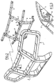
- Fig. 2 shows the car crash protector 2 in disassembled parts.
- a cover element 5 manufactured from deformable plastic can be connected to a metal support construction 7 using connecting members 6.
- the support construction 7 is built up of profile parts 8 made of relatively thin plate material.
- Support construction 7 can be fixed to the vehicle 1 (not shown here) using coupling elements 9.
- the upper two coupling elements 9 shown here are provided with a weakened portion 10, whereby they are deformable.
- respective recesses 11, 12 for insertion of the connecting members 6.
- Fig. 3 shows in cross section a part of the car crash protector 2 in assembled state. Shown clearly is a free space 13 which is situated on the front side between the cover element 5 and the support construction 7.
- Fig. 4a shows a cross section of the car crash protector 2 of the foregoing figures in an unloaded and undeformed state.
- fig. 4b the same cross section is shown during a light collision.
- the plastic cover element 5 thereby receives a dent 14 which is situated in the space 13 which originally existed between cover element 5 and support construction 7.
- the plastic cover element 5 can be embodied such that a small dent 14 disappears again after a collision because the deformed material springs back to the original shape (see fig. 4a). Energy released during the collision is herein absorbed by the deforming of cover element 5; the risk of injury to fellow road-users or damage to other objects is hereby limited. Subsequently shown in fig. 4c is the situation during a heavy collision.
- cover element 5 is not capable of absorbing by means of a dent 15 all the energy released during the collision. The remaining energy will then be absorbed to an at least significant degree by the deformation of the support construction 7.
- Safety is hereby further enhanced, since all energy absorbed by the car crash protector 2 cannot damage a fellow road-user or other object.
- the upper coupling elements 9 will also deform close to the arranged weakened portions 10 so that again a part of the energy is also hereby absorbed.
- Fig. 5 shows a car crash protector 2, wherein the upper coupling elements are formed by at least one spring 16.
- a spring 16 is also capable of storing energy. After compression of the spring 16 it can spring back again into the original position. This perhaps more expensive construction therefore has the advantage that a possible deformation of the mounting of car crash protector 2 to vehicle 1 is only of a temporary nature.
Abstract
Description
Claims (4)
- Device (2) for fixing to the front part of a vehicle (1), comprising a support construction (7) which is assembled from profile parts (8) manufactured from metal plate material and provided with attachment points (9) for fixing thereof to the vehicle (1), a plastic cover element (5), manufactured from deformable plastic, for separately covering the sides of each profile part (8) facing away from the vehicle (1), and means (6) for connecting the cover element (5) to the support construction (7), wherein between the profile parts (8) of the support construction (7) and the cover element (5) mounted on the support construction (7) free spaces are present,
characterized in thatthe support construction (7) is connected to the vehicle (1) with interposing of at least one controlled deformable element (9) for absorbing energy during deformation. - Device (2) as claimed in claim 1,
characterized in thatthe energy-absorbing element (9) is a deformable mounting bracket (9), with at least one weakened position (10). - Device (2) as claimed in claim 1 or 2,
characterized in thatenergy-absorbing element (9) is a spring. - Device (2) as claimed in any of the foregoing claims,
characterized in thatthe parts of the cover element (5) located closest to the sides of the vehicle (1) project over the support construction (7).
Applications Claiming Priority (3)
| Application Number | Priority Date | Filing Date | Title |
|---|---|---|---|
| NL9401181A NL9401181A (en) | 1994-07-18 | 1994-07-18 | Car screen. |
| NL9401181 | 1994-07-18 | ||
| PCT/NL1995/000250 WO1996002406A1 (en) | 1994-07-18 | 1995-07-17 | Car crash protector |
Publications (2)
| Publication Number | Publication Date |
|---|---|
| EP0773876A1 EP0773876A1 (en) | 1997-05-21 |
| EP0773876B1 true EP0773876B1 (en) | 1999-01-20 |
Family
ID=19864445
Family Applications (1)
| Application Number | Title | Priority Date | Filing Date |
|---|---|---|---|
| EP95925161A Expired - Lifetime EP0773876B1 (en) | 1994-07-18 | 1995-07-17 | Car crash protector |
Country Status (11)
| Country | Link |
|---|---|
| US (1) | US6022057A (en) |
| EP (1) | EP0773876B1 (en) |
| JP (1) | JPH10502592A (en) |
| AT (1) | ATE175931T1 (en) |
| CA (1) | CA2195081A1 (en) |
| DE (1) | DE69507487T2 (en) |
| DK (1) | DK0773876T3 (en) |
| ES (1) | ES2126910T3 (en) |
| GR (1) | GR3029782T3 (en) |
| NL (1) | NL9401181A (en) |
| WO (1) | WO1996002406A1 (en) |
Families Citing this family (23)
| Publication number | Priority date | Publication date | Assignee | Title |
|---|---|---|---|---|
| DE29500106U1 (en) * | 1995-01-04 | 1996-05-09 | Rumpp Gerhard | Front protection bar |
| DE19852959C2 (en) * | 1998-11-17 | 2002-09-12 | Daimler Chrysler Ag | Arrangement of a front guard on a motor vehicle front |
| US6231093B1 (en) * | 1999-02-02 | 2001-05-15 | Ron D. Storer | Push bar mounting system |
| US6318773B2 (en) * | 1999-02-02 | 2001-11-20 | Ron D. Storer | Push bar mounting system |
| DE19941939A1 (en) * | 1999-09-03 | 2001-03-22 | Daimler Chrysler Ag | Front impact crash protection system movable in vehicle length direction, comprises crash barrier mounted behind front panelling of vehicle |
| DE19944670B4 (en) * | 1999-09-17 | 2009-03-12 | Volkswagen Ag | Front bumper assembly for a motor vehicle |
| US6367869B1 (en) | 2000-07-26 | 2002-04-09 | Ford Global Technologies, Inc. | Energy management system and method for an extruded aluminum vehicle subframe |
| US6398276B1 (en) | 2001-04-12 | 2002-06-04 | Herman L. Smith | Bumper guard |
| ES2186554B1 (en) * | 2001-07-10 | 2004-08-16 | Mondragon Automocion B.C.M., S. Coop | BUMPER. |
| US6905153B2 (en) * | 2002-11-11 | 2005-06-14 | Pro-Gard Industries, L.P. | Push bumper |
| US7077439B2 (en) * | 2003-08-25 | 2006-07-18 | General Motors Corporation | Vehicle bumper and method of making same |
| JP2007513832A (en) * | 2003-12-09 | 2007-05-31 | デコマ (ジャーマニー) ゲゼルシャフト ミット ベシュレンクテル ハフツング | Structural components for automotive bumper structures |
| EP1582413A1 (en) * | 2004-03-30 | 2005-10-05 | Ford Global Technologies, Inc. | A bumper device for a vehicle |
| US7246832B2 (en) * | 2005-02-14 | 2007-07-24 | General Motors Corporation | Vehicle grille guard assembly |
| EP2269875A1 (en) * | 2006-04-18 | 2011-01-05 | Ian Antony Finney | Bull bar arrangement on a motor vehicle front |
| US7306271B2 (en) * | 2006-04-26 | 2007-12-11 | Gm Global Technology Operations, Inc. | Aluminum brush guard assembly |
| US7703819B2 (en) * | 2006-06-21 | 2010-04-27 | Concept Mouldings Ltd. | Pedestrian protection |
| US7445259B1 (en) | 2007-06-08 | 2008-11-04 | Ford Global Technologies, Llc | Fascia anti-rattle springs |
| US8585107B2 (en) | 2011-08-31 | 2013-11-19 | Iddea California, Llc | Push bumper and mounting system |
| JP6632869B2 (en) * | 2015-11-09 | 2020-01-22 | アイシン精機株式会社 | Radiator support member |
| US10116610B2 (en) | 2016-08-31 | 2018-10-30 | Keystone Automotive Operations, Inc. | Automotive wheel overlay attachment system |
| CN107054267A (en) * | 2017-04-10 | 2017-08-18 | 上海蔚来汽车有限公司 | Automobile plated item, automobile plated item mould and its manufacture method |
| EP3892501A1 (en) * | 2020-04-06 | 2021-10-13 | 4Extreme Trading S.r.l. | Heavy-duty bumper |
Family Cites Families (9)
| Publication number | Priority date | Publication date | Assignee | Title |
|---|---|---|---|---|
| US3827741A (en) * | 1973-08-06 | 1974-08-06 | Ford Motor Co | Resilient bumper assembly |
| DE2550019A1 (en) * | 1975-11-07 | 1977-05-12 | Volkswagenwerk Ag | Bumper bar for car - with open profile against open profile on car body to spread impact force |
| DE3020997C2 (en) * | 1980-06-03 | 1986-10-30 | Wilhelm Karmann GmbH, 4500 Osnabrück | Bumpers for automobiles |
| JPS60209344A (en) * | 1984-04-04 | 1985-10-21 | Nissan Motor Co Ltd | Bumper structure for automobile |
| US4944540A (en) * | 1989-05-24 | 1990-07-31 | Ford Motor Company | Sliding radiator grill |
| GB8918388D0 (en) * | 1989-08-11 | 1989-09-20 | Jib Engineering Ltd | Improvements relating to nudge bars |
| DE9105739U1 (en) * | 1991-05-08 | 1991-07-18 | Haslbeck Technik Gmbh, 8260 Muehldorf, De | |
| DE4240237C2 (en) * | 1992-11-30 | 1995-02-16 | Gkn Automotive Ag | Upsetting pipe |
| DE9306545U1 (en) * | 1993-04-30 | 1993-09-23 | Pfeba Kunststofftechnik Gmbh | FRONT PROTECTION PART FOR A MOTOR VEHICLE |
-
1994
- 1994-07-18 NL NL9401181A patent/NL9401181A/en not_active Application Discontinuation
-
1995
- 1995-07-17 DE DE69507487T patent/DE69507487T2/en not_active Expired - Fee Related
- 1995-07-17 CA CA002195081A patent/CA2195081A1/en not_active Abandoned
- 1995-07-17 ES ES95925161T patent/ES2126910T3/en not_active Expired - Lifetime
- 1995-07-17 US US08/776,043 patent/US6022057A/en not_active Expired - Fee Related
- 1995-07-17 DK DK95925161T patent/DK0773876T3/en active
- 1995-07-17 AT AT95925161T patent/ATE175931T1/en not_active IP Right Cessation
- 1995-07-17 WO PCT/NL1995/000250 patent/WO1996002406A1/en active IP Right Grant
- 1995-07-17 JP JP8504908A patent/JPH10502592A/en active Pending
- 1995-07-17 EP EP95925161A patent/EP0773876B1/en not_active Expired - Lifetime
-
1999
- 1999-03-23 GR GR990400870T patent/GR3029782T3/en unknown
Also Published As
| Publication number | Publication date |
|---|---|
| ATE175931T1 (en) | 1999-02-15 |
| NL9401181A (en) | 1996-03-01 |
| DK0773876T3 (en) | 1999-08-09 |
| EP0773876A1 (en) | 1997-05-21 |
| AU698083B2 (en) | 1998-10-22 |
| AU2938095A (en) | 1996-02-16 |
| CA2195081A1 (en) | 1996-02-01 |
| US6022057A (en) | 2000-02-08 |
| ES2126910T3 (en) | 1999-04-01 |
| WO1996002406A1 (en) | 1996-02-01 |
| DE69507487D1 (en) | 1999-03-04 |
| JPH10502592A (en) | 1998-03-10 |
| GR3029782T3 (en) | 1999-06-30 |
| DE69507487T2 (en) | 1999-05-27 |
Similar Documents
| Publication | Publication Date | Title |
|---|---|---|
| EP0773876B1 (en) | Car crash protector | |
| JP2001187588A (en) | Front end structure of vehicle | |
| US6412581B2 (en) | Radiator mounting structure | |
| CN105752003B (en) | Energy absorption device with locking structure and grating using same | |
| JP4886768B2 (en) | Car front | |
| JP2004119379A (en) | Head lamp equipped with shock energy absorption means | |
| GB0019476D0 (en) | A grill for a land vehicle and also a land vehicle having a grill | |
| US7325861B2 (en) | Structural component of a motor vehicle bumper arrangement | |
| US4644447A (en) | Lamp unit for vehicles | |
| ATA134990A (en) | SHOCK ABSORBERS, ESPECIALLY FOR MOTOR VEHICLES | |
| US20060237998A1 (en) | Stop support for the front hood of a motor vehicle | |
| SG42372A1 (en) | Ballistic grille for special purpose vehicle | |
| US4424996A (en) | Combination bumper-and-radiator structure | |
| CN113147568B (en) | Front through lamp assembly | |
| US7108308B2 (en) | Safety mirror support for sun visors | |
| JP2005518294A (en) | Front panel of a car with a bumper beam | |
| AU698083C (en) | Car crash protector | |
| US20090026798A1 (en) | Pedestrian protection apparatus for front end of vehicle | |
| US6962380B2 (en) | Rear bumper assembly structure for vehicle | |
| USD382237S (en) | Bumper facade for motor vehicle | |
| US1610516A (en) | Auto bumper | |
| JPH0371290B2 (en) | ||
| EP3865351A1 (en) | Frontal protection system for vehicles | |
| JPS6135468Y2 (en) | ||
| JP4176207B2 (en) | Front bumper mounting structure |
Legal Events
| Date | Code | Title | Description |
|---|---|---|---|
| PUAI | Public reference made under article 153(3) epc to a published international application that has entered the european phase |
Free format text: ORIGINAL CODE: 0009012 |
|
| 17P | Request for examination filed |
Effective date: 19970115 |
|
| AK | Designated contracting states |
Kind code of ref document: A1 Designated state(s): AT BE CH DE DK ES FR GB GR IE IT LI NL PT SE |
|
| 17Q | First examination report despatched |
Effective date: 19970619 |
|
| GRAG | Despatch of communication of intention to grant |
Free format text: ORIGINAL CODE: EPIDOS AGRA |
|
| GRAG | Despatch of communication of intention to grant |
Free format text: ORIGINAL CODE: EPIDOS AGRA |
|
| GRAG | Despatch of communication of intention to grant |
Free format text: ORIGINAL CODE: EPIDOS AGRA |
|
| GRAH | Despatch of communication of intention to grant a patent |
Free format text: ORIGINAL CODE: EPIDOS IGRA |
|
| GRAH | Despatch of communication of intention to grant a patent |
Free format text: ORIGINAL CODE: EPIDOS IGRA |
|
| GRAA | (expected) grant |
Free format text: ORIGINAL CODE: 0009210 |
|
| AK | Designated contracting states |
Kind code of ref document: B1 Designated state(s): AT BE CH DE DK ES FR GB GR IE IT LI NL PT SE |
|
| REF | Corresponds to: |
Ref document number: 175931 Country of ref document: AT Date of ref document: 19990215 Kind code of ref document: T |
|
| REG | Reference to a national code |
Ref country code: CH Ref legal event code: NV Representative=s name: ARNOLD & SIEDSMA AG Ref country code: CH Ref legal event code: EP |
|
| REG | Reference to a national code |
Ref country code: IE Ref legal event code: FG4D |
|
| ITF | It: translation for a ep patent filed |
Owner name: STUDIO INGG. FISCHETTI & WEBER |
|
| REF | Corresponds to: |
Ref document number: 69507487 Country of ref document: DE Date of ref document: 19990304 |
|
| ET | Fr: translation filed | ||
| REG | Reference to a national code |
Ref country code: ES Ref legal event code: FG2A Ref document number: 2126910 Country of ref document: ES Kind code of ref document: T3 |
|
| PG25 | Lapsed in a contracting state [announced via postgrant information from national office to epo] |
Ref country code: DE Free format text: LAPSE BECAUSE OF FAILURE TO SUBMIT A TRANSLATION OF THE DESCRIPTION OR TO PAY THE FEE WITHIN THE PRESCRIBED TIME-LIMIT Effective date: 19990421 |
|
| REG | Reference to a national code |
Ref country code: PT Ref legal event code: SC4A Free format text: AVAILABILITY OF NATIONAL TRANSLATION Effective date: 19990215 |
|
| REG | Reference to a national code |
Ref country code: DK Ref legal event code: T3 |
|
| PLBE | No opposition filed within time limit |
Free format text: ORIGINAL CODE: 0009261 |
|
| STAA | Information on the status of an ep patent application or granted ep patent |
Free format text: STATUS: NO OPPOSITION FILED WITHIN TIME LIMIT |
|
| 26N | No opposition filed | ||
| PGFP | Annual fee paid to national office [announced via postgrant information from national office to epo] |
Ref country code: GR Payment date: 20010731 Year of fee payment: 7 |
|
| REG | Reference to a national code |
Ref country code: GB Ref legal event code: IF02 |
|
| PG25 | Lapsed in a contracting state [announced via postgrant information from national office to epo] |
Ref country code: GR Free format text: LAPSE BECAUSE OF NON-PAYMENT OF DUE FEES Effective date: 20030206 |
|
| PGFP | Annual fee paid to national office [announced via postgrant information from national office to epo] |
Ref country code: BE Payment date: 20040729 Year of fee payment: 10 |
|
| PGFP | Annual fee paid to national office [announced via postgrant information from national office to epo] |
Ref country code: SE Payment date: 20040730 Year of fee payment: 10 Ref country code: DK Payment date: 20040730 Year of fee payment: 10 |
|
| PGFP | Annual fee paid to national office [announced via postgrant information from national office to epo] |
Ref country code: PT Payment date: 20050629 Year of fee payment: 11 Ref country code: IE Payment date: 20050629 Year of fee payment: 11 |
|
| PG25 | Lapsed in a contracting state [announced via postgrant information from national office to epo] |
Ref country code: IT Free format text: LAPSE BECAUSE OF NON-PAYMENT OF DUE FEES Effective date: 20050717 |
|
| PG25 | Lapsed in a contracting state [announced via postgrant information from national office to epo] |
Ref country code: SE Free format text: LAPSE BECAUSE OF NON-PAYMENT OF DUE FEES Effective date: 20050718 |
|
| PGFP | Annual fee paid to national office [announced via postgrant information from national office to epo] |
Ref country code: FR Payment date: 20050729 Year of fee payment: 11 Ref country code: ES Payment date: 20050729 Year of fee payment: 11 |
|
| PGFP | Annual fee paid to national office [announced via postgrant information from national office to epo] |
Ref country code: NL Payment date: 20050730 Year of fee payment: 11 |
|
| PG25 | Lapsed in a contracting state [announced via postgrant information from national office to epo] |
Ref country code: BE Free format text: LAPSE BECAUSE OF NON-PAYMENT OF DUE FEES Effective date: 20050731 |
|
| PG25 | Lapsed in a contracting state [announced via postgrant information from national office to epo] |
Ref country code: DK Free format text: LAPSE BECAUSE OF NON-PAYMENT OF DUE FEES Effective date: 20050801 |
|
| PGFP | Annual fee paid to national office [announced via postgrant information from national office to epo] |
Ref country code: CH Payment date: 20050802 Year of fee payment: 11 |
|
| EUG | Se: european patent has lapsed | ||
| REG | Reference to a national code |
Ref country code: DK Ref legal event code: EBP |
|
| PG25 | Lapsed in a contracting state [announced via postgrant information from national office to epo] |
Ref country code: IE Free format text: LAPSE BECAUSE OF NON-PAYMENT OF DUE FEES Effective date: 20060717 |
|
| PG25 | Lapsed in a contracting state [announced via postgrant information from national office to epo] |
Ref country code: LI Free format text: LAPSE BECAUSE OF NON-PAYMENT OF DUE FEES Effective date: 20060731 Ref country code: CH Free format text: LAPSE BECAUSE OF NON-PAYMENT OF DUE FEES Effective date: 20060731 |
|
| PG25 | Lapsed in a contracting state [announced via postgrant information from national office to epo] |
Ref country code: PT Free format text: LAPSE BECAUSE OF NON-PAYMENT OF DUE FEES Effective date: 20070117 |
|
| PG25 | Lapsed in a contracting state [announced via postgrant information from national office to epo] |
Ref country code: NL Free format text: LAPSE BECAUSE OF NON-PAYMENT OF DUE FEES Effective date: 20070201 |
|
| REG | Reference to a national code |
Ref country code: PT Ref legal event code: MM4A Free format text: LAPSE DUE TO NON-PAYMENT OF FEES Effective date: 20070117 |
|
| REG | Reference to a national code |
Ref country code: CH Ref legal event code: PL |
|
| NLV4 | Nl: lapsed or anulled due to non-payment of the annual fee |
Effective date: 20070201 |
|
| REG | Reference to a national code |
Ref country code: IE Ref legal event code: MM4A |
|
| REG | Reference to a national code |
Ref country code: FR Ref legal event code: ST Effective date: 20070330 |
|
| REG | Reference to a national code |
Ref country code: ES Ref legal event code: FD2A Effective date: 20060718 |
|
| BERE | Be: lapsed |
Owner name: *KELOWNA HECTARES B.V. Effective date: 20050731 |
|
| PG25 | Lapsed in a contracting state [announced via postgrant information from national office to epo] |
Ref country code: ES Free format text: LAPSE BECAUSE OF NON-PAYMENT OF DUE FEES Effective date: 20060718 |
|
| PG25 | Lapsed in a contracting state [announced via postgrant information from national office to epo] |
Ref country code: FR Free format text: LAPSE BECAUSE OF NON-PAYMENT OF DUE FEES Effective date: 20060731 |
|
| PGFP | Annual fee paid to national office [announced via postgrant information from national office to epo] |
Ref country code: DE Payment date: 20080731 Year of fee payment: 14 |
|
| PGFP | Annual fee paid to national office [announced via postgrant information from national office to epo] |
Ref country code: AT Payment date: 20080728 Year of fee payment: 14 |
|
| PGFP | Annual fee paid to national office [announced via postgrant information from national office to epo] |
Ref country code: GB Payment date: 20080731 Year of fee payment: 14 |
|
| GBPC | Gb: european patent ceased through non-payment of renewal fee |
Effective date: 20090717 |
|
| PG25 | Lapsed in a contracting state [announced via postgrant information from national office to epo] |
Ref country code: GB Free format text: LAPSE BECAUSE OF NON-PAYMENT OF DUE FEES Effective date: 20090717 |
|
| PG25 | Lapsed in a contracting state [announced via postgrant information from national office to epo] |
Ref country code: DE Free format text: LAPSE BECAUSE OF NON-PAYMENT OF DUE FEES Effective date: 20100202 Ref country code: AT Free format text: LAPSE BECAUSE OF NON-PAYMENT OF DUE FEES Effective date: 20090717 |