EP1816612A1 - Bill identifying/counting machine - Google Patents
Bill identifying/counting machine Download PDFInfo
- Publication number
- EP1816612A1 EP1816612A1 EP04773792A EP04773792A EP1816612A1 EP 1816612 A1 EP1816612 A1 EP 1816612A1 EP 04773792 A EP04773792 A EP 04773792A EP 04773792 A EP04773792 A EP 04773792A EP 1816612 A1 EP1816612 A1 EP 1816612A1
- Authority
- EP
- European Patent Office
- Prior art keywords
- counting
- discriminating
- bill
- occupation
- bill discriminating
- Prior art date
- Legal status (The legal status is an assumption and is not a legal conclusion. Google has not performed a legal analysis and makes no representation as to the accuracy of the status listed.)
- Withdrawn
Links
Images

Classifications
-
- G—PHYSICS
- G07—CHECKING-DEVICES
- G07D—HANDLING OF COINS OR VALUABLE PAPERS, e.g. TESTING, SORTING BY DENOMINATIONS, COUNTING, DISPENSING, CHANGING OR DEPOSITING
- G07D11/00—Devices accepting coins; Devices accepting, dispensing, sorting or counting valuable papers
- G07D11/40—Device architecture, e.g. modular construction
-
- G—PHYSICS
- G07—CHECKING-DEVICES
- G07D—HANDLING OF COINS OR VALUABLE PAPERS, e.g. TESTING, SORTING BY DENOMINATIONS, COUNTING, DISPENSING, CHANGING OR DEPOSITING
- G07D11/00—Devices accepting coins; Devices accepting, dispensing, sorting or counting valuable papers
- G07D11/50—Sorting or counting valuable papers
-
- G—PHYSICS
- G07—CHECKING-DEVICES
- G07D—HANDLING OF COINS OR VALUABLE PAPERS, e.g. TESTING, SORTING BY DENOMINATIONS, COUNTING, DISPENSING, CHANGING OR DEPOSITING
- G07D7/00—Testing specially adapted to determine the identity or genuineness of valuable papers or for segregating those which are unacceptable, e.g. banknotes that are alien to a currency
-
- G—PHYSICS
- G07—CHECKING-DEVICES
- G07D—HANDLING OF COINS OR VALUABLE PAPERS, e.g. TESTING, SORTING BY DENOMINATIONS, COUNTING, DISPENSING, CHANGING OR DEPOSITING
- G07D7/00—Testing specially adapted to determine the identity or genuineness of valuable papers or for segregating those which are unacceptable, e.g. banknotes that are alien to a currency
- G07D7/06—Testing specially adapted to determine the identity or genuineness of valuable papers or for segregating those which are unacceptable, e.g. banknotes that are alien to a currency using wave or particle radiation
- G07D7/12—Visible light, infrared or ultraviolet radiation
-
- G—PHYSICS
- G07—CHECKING-DEVICES
- G07D—HANDLING OF COINS OR VALUABLE PAPERS, e.g. TESTING, SORTING BY DENOMINATIONS, COUNTING, DISPENSING, CHANGING OR DEPOSITING
- G07D7/00—Testing specially adapted to determine the identity or genuineness of valuable papers or for segregating those which are unacceptable, e.g. banknotes that are alien to a currency
- G07D7/20—Testing patterns thereon
-
- G—PHYSICS
- G07—CHECKING-DEVICES
- G07F—COIN-FREED OR LIKE APPARATUS
- G07F7/00—Mechanisms actuated by objects other than coins to free or to actuate vending, hiring, coin or paper currency dispensing or refunding apparatus
- G07F7/04—Mechanisms actuated by objects other than coins to free or to actuate vending, hiring, coin or paper currency dispensing or refunding apparatus by paper currency
-
- B—PERFORMING OPERATIONS; TRANSPORTING
- B65—CONVEYING; PACKING; STORING; HANDLING THIN OR FILAMENTARY MATERIAL
- B65H—HANDLING THIN OR FILAMENTARY MATERIAL, e.g. SHEETS, WEBS, CABLES
- B65H2701/00—Handled material; Storage means
- B65H2701/10—Handled articles or webs
- B65H2701/19—Specific article or web
- B65H2701/1912—Banknotes, bills and cheques or the like
Definitions
- the present invention relates to a bill discriminating and counting apparatus which discriminates a denomination of a bill received through a hopper while counting a total amount of the received bills or the number of bills in each denomination, particularly to the bill discriminating and counting apparatus having a function in which two operators can operate one apparatus.
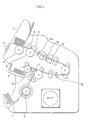
- Fig. 1 is a longitudinal cross-sectional view showing an internal structure of the conventional bill discriminating and counting apparatus.
- a feeding roller 5 feeds the bill placed in a hopper 1 to a transport path of the bill discriminating and counting apparatus, and the bill is carried by plural carrying rollers 6.
- the bill passes through detection sensors 7a and 7b, and a bill discriminating sensor 8 discriminates the denomination and authenticity. Then, the bill passes through a detection sensor 7c, and the bill is received between blades of a rotating impeller 9 when the bill is normal , and the bill is aligned and collected in a stacker 2. On the other hand, when the bill discriminating sensor judges that the bill is a forged bill, a solenoid 10 is operated to move a branching pawl 11 downward, and the bill is delivered to a rejection section 3.
- the numeral 4 designates an operation and display section which performs various settings in performing the bill discriminating and counting process .
- a bill credit processing apparatus used in a teller's window of a bank is installed and commonlyused between two tellers, and the two tellers can operate the bill credit processing apparatus from both sides through a teller's machine which is of an upper-level apparatus.
- the apparatus when the apparatus is continuously set in the state occupied by one of the tellers until one transaction is ended, the other teller cannot perform the counting and storing operation with the apparatus, even if the counting and storing operation is interrupted by some reason.
- the other teller uses the apparatus , because it is necessary that the interrupted process be reset to switch the apparatus to the state occupied by the other teller, the process initially performed by one of the tellers is wasted.
- the conventional apparatus has a problem on working efficiency.
- a bill credit processing apparatus having a function in which the two tellers can use the one apparatus (for example, see Japanese Patent Application Publication No. 7-118032 ).
- the bill credit processing apparatus disclosed in Japanese Patent Application Publication No. 7-118032 is specialized in the apparatus which is commonly used by the bank tellers, the bill credit processing apparatus is located under a teller's machine occupied by each teller, and the occupation state is switched by the teller's machine.
- the occupation is not determined by an instruction from the upper-level apparatus such as the teller's machine, and originally the one teller uses the one bill discriminating and counting apparatus from a commonsense standpoint. Therefore, design is not made such that the two operators can commonly use the one apparatus. Accordingly, in a store or a financial institution in which the bill discriminating and counting apparatus is used, it is necessary that the number of bill discriminating and counting apparatus be required as many operators as there are, which results in a problem from the standpoint of capital investment.
- an object of the invention is to provide a bill discriminating and counting apparatus in which the two operators can commonly use the one apparatus, and thereby the efficiency in the bill discriminating and counting work is enhanced, and total cost of introducing the apparatus is decreased.
- a bill discriminating and counting apparatus includes a hopper which receives bills to be processed; a feeding and carrying section which feeds the bills received by said hopper one by one to a transport path and carries the bill; a discriminating and counting section which is provided on a downstream side of said feeding and carrying section, said discriminating and counting section discriminating denominations of the carried bills and counting the bills; and a stacker which is provided on the downstream side of said discriminating and counting section, said stacker collecting the bills in which normality is confirmed, wherein two pairs of a process instruction button for instructing start/stop of a discriminating and counting process and an approval button for approving counting result are provided, two independent storage areas are provided in a storage area in which the counting result is stored, said counting result is stored in the corresponding storage area while said each storage area is associated with the pair of the process instruction button and the approval button,
- the occupation state of the bill discriminating and counting apparatus is switched by pressing said process instruction button.
- the present invention relates to a bill discriminating and counting apparatus having a function in which two operators can commonly operate one apparatus. That is, two pairs of a process instruction button for instructing start/stop of a discriminating and counting process and an approval button for approving counting result are provided, two independent storage areas are provided in a storage area in which the counting result is stored, the counting result is stored in the corresponding storage area while each storage area is associated with the pair of the process instruction button and the approval button, and two operators can commonly use the one bill discriminating and counting apparatus by providing occupation switching means for switching an occupation state of the bill discriminating and counting apparatus and occupation state display means for displaying a current occupation state.
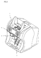
- Fig. 2 is a perspective view showing an appearance of the bill discriminating and counting apparatus according to the invention.
- the bills put in from the hopper 1 are discriminated and counted by the bill discriminating and counting apparatus, and the bills are aligned and collected in the stacker 2.
- the bill in which the process cannot be performed due to the forged bill or dirt is delivered to the rejection section 3.
- the operation and display section 4 includes various operation buttons, and two users can commonly use the one bill discriminating and counting apparatus by operating the operation and display section 4.
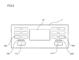
- Fig. 3 shows the operation and display section 4 of the bill discriminating and counting apparatus according to an embodiment of the invention.
- a liquid crystal panel 40 which performs various displays, is located in the center of the operation and display section 4.
- Each of pairs of START/STOP keys 41, ACCEPT keys 42 , and occupation display EEDs 43 is arranged while divided on the right and left sides of the liquid crystal panel 40.
- other keys shown by dotted lines are used to set various operations, description is neglected because these keys have no immediate relationship to the invention.
- the keys (41 and 42) having the same functions are arranged while divided on the right and left sides, the two operators can easily operate the bill discriminating and counting apparatus when the bill discriminating and counting apparatus is placed between the two operators.
- Fig. 4 shows a part of a control block diagram of the bill discriminating and counting apparatus according to the invention.
- a process instruction button L (41L) and a process instruction button R (41R) correspond to the START/STOP key 41 of Fig. 3, and an approval button L (42L) and an approval button R (42R) correspond to the ACCEPT key 42 of Fig. 3.
- a storage area L (60L) and a storage area R (60R) are storage areas in which each of the sum of counting result is stored when each of the R and L-side operators performs the discriminating and counting process.
- a control section 50 writes the counting result in the storage area L (60L) and storage area R (60R).
- the outputs of the counting results (total amounts) stored in the storage areas 60L and 60R can be outputted to external printers 80L and 80R, or personal computers (PC) respectively.
- the bill discriminating and counting apparatus is connected to the printers or PCs through interfaces (I/F) 70.
- the R-side operator occupies the apparatus when the power is turned on. That is, the R-side occupation display LED 43R is lit.
- the L-side operator can press the process instruction button L (41L) during a standby time to switch the apparatus to the L-side occupation. In this case, the L-side occupation display LED 43L is lit.
- the pairs of the START/STOP keys 41 and the ACCEPT keys 42 are arranged on the right and left sides such that the two operators can commonly use the one apparatus. Accordingly, in the case where the apparatus has the setting (single-headed setting) in which either of the operators singularly uses the apparatus, because both the right and left keys become simultaneously enabled, the operator can operates the keys according to a dominant arm of the operator, which further improves the usability.
- Table 1 shows patterns of operation modes of the bill discriminating and counting apparatus according to the invention. The modes will be described below with reference to Table 1.
- online means that the computer (including PC) is connected to I/F 70 of Fig. 4
- off-line means that the computer is not connected to I/F 70
- printer setting OFF means that the printer is not connected.
- Both the L-side and R-side keys are enabled, and the total amount is stored in the R-side storage area. Both the occupation display LEDs are lit.
- Both the L-side and R-side keys are enabled, and the total amount is stored in the R-side storage area. Both the occupation display LEDs are lit. The counting result is printed when either of the ACCEPT keys 42 is pressed.
- the R-side LED is lit while the L-side LED is turned off.
- the apparatus is switched to the L-side occupation, and the R-side LED is turned off while the L-side LED is lit.
- the counting results are separately stored in L-side and R-side storage areas.
- the mode (5) is similar to the mode (3).
- the ACCEPT key 42L or 42R is pressed, the counting results is printed by the printers respectively.
- the R-side LED blinks while the L-side LED is turned off.
- the apparatus is switched to the L-side occupation, and the R-side LED is turned off while the L-side LED is lit.
- the counting results are separately stored in the L-side and R-side storage areas.
- the apparatus is switched to the R-side occupation, and the R-side is returned to online setting.
- the R-side LED blinks while the L-side LED is turned off.
- the apparatus is switched to the L-side occupation, and the R-side LED is turned off while the L-side LED is lit.
- the counting results are separately stored in the L-side and R-side storage areas.
- the ACCEPT key 42L is pressed, the counting result is printed by the L-side printer.
- the R-side START/STOP key 41L is pressed for at least two seconds during the standby time, or when the apparatus is switched to remote control occupation by PC, the apparatus is switched to the R-side occupation, and the R-side is returned to the online setting.
- the R-side LED blinks while the L-side LED is turned off.
- the apparatus is switched to the L-side occupation, and the R-side LED is turned off while the L-side LED blinks.
- the counting results are separately stored in the L-side and R-side storage areas.
- Both the L-side and R-side keys are disabled, and the remote control is performed by the connected PC.
- the total amount is stored in the R-side storage area.
- Both the occupation display LEDs blink.
- the two process instruction buttons are provided, and the storage areas are provided in association with the process instruction buttons respectively, so that the processing result can be retained in each operator. Therefore, although the two operators cannot simultaneously operate the apparatus, apparently the operators can use the apparatus as the two apparatus, which results in the excellent cost performance.
Landscapes
- Physics & Mathematics (AREA)
- General Physics & Mathematics (AREA)
- Health & Medical Sciences (AREA)
- General Health & Medical Sciences (AREA)
- Toxicology (AREA)
- Financial Or Insurance-Related Operations Such As Payment And Settlement (AREA)
- Pinball Game Machines (AREA)
- Control Of Vending Devices And Auxiliary Devices For Vending Devices (AREA)
- Inspection Of Paper Currency And Valuable Securities (AREA)
Abstract
Description
- The present invention relates to a bill discriminating and counting apparatus which discriminates a denomination of a bill received through a hopper while counting a total amount of the received bills or the number of bills in each denomination, particularly to the bill discriminating and counting apparatus having a function in which two operators can operate one apparatus.
- There is a well known bill discriminating and counting apparatus, in which bills having mixed denominations are collectively received from a hopper, the bills are fed and carried one by one, the bills are counted while the denomination and authenticity of the bills are discriminated, and the total amount of the normal bill or the number of bills in each denomination is counted and displayed (for example, see
Japanese Patent Application Laid-Open No. 2003-296801 - A structure and an operation of a conventional bill discriminating and counting apparatus will be described with reference to Fig. 1. Fig. 1 is a longitudinal cross-sectional view showing an internal structure of the conventional bill discriminating and counting apparatus.
- A
feeding roller 5 feeds the bill placed in ahopper 1 to a transport path of the bill discriminating and counting apparatus, and the bill is carried byplural carrying rollers 6. - During the bill carrying, the bill passes through
detection sensors discriminating sensor 8 discriminates the denomination and authenticity. Then, the bill passes through a detection sensor 7c, and the bill is received between blades of a rotatingimpeller 9 when the bill is normal , and the bill is aligned and collected in astacker 2. On the other hand, when the bill discriminating sensor judges that the bill is a forged bill, asolenoid 10 is operated to move a branchingpawl 11 downward, and the bill is delivered to arejection section 3. - The
numeral 4 designates an operation and display section which performs various settings in performing the bill discriminating and counting process . - Conventionally, sometimes a bill credit processing apparatus used in a teller's window of a bank is installed and commonlyused between two tellers, and the two tellers can operate the bill credit processing apparatus from both sides through a teller's machine which is of an upper-level apparatus.
- In the conventional apparatus, because it is necessary that the bills sequentially put in the hoppers by the right and left tellers be counted and stored without mixing the bills, it is necessary that the apparatus be set in the state occupied by either of the tellers in each transaction from the beginning to the end.
- However, when the apparatus is continuously set in the state occupied by one of the tellers until one transaction is ended, the other teller cannot perform the counting and storing operation with the apparatus, even if the counting and storing operation is interrupted by some reason. When the other teller uses the apparatus , because it is necessary that the interrupted process be reset to switch the apparatus to the state occupied by the other teller, the process initially performed by one of the tellers is wasted.
- Therefore, the conventional apparatus has a problem on working efficiency. In consideration with these problems, there is proposed a bill credit processing apparatus having a function in which the two tellers can use the one apparatus (for example, see
Japanese Patent Application Publication No. 7-118032 - The bill credit processing apparatus disclosed in
Japanese Patent Application Publication No. 7-118032 - However, in the conventional bill discriminating and counting apparatus, the occupation is not determined by an instruction from the upper-level apparatus such as the teller's machine, and originally the one teller uses the one bill discriminating and counting apparatus from a commonsense standpoint. Therefore, design is not made such that the two operators can commonly use the one apparatus. Accordingly, in a store or a financial institution in which the bill discriminating and counting apparatus is used, it is necessary that the number of bill discriminating and counting apparatus be required as many operators as there are, which results in a problem from the standpoint of capital investment.
- In view of the foregoing, an object of the invention is to provide a bill discriminating and counting apparatus in which the two operators can commonly use the one apparatus, and thereby the efficiency in the bill discriminating and counting work is enhanced, and total cost of introducing the apparatus is decreased.
- The present invention relates to a bill discriminating and counting apparatus having a function in which two operators can commonly operate one apparatus. In order to achieve the above object, a bill discriminating and counting apparatus according to an aspect of the invention includes a hopper which receives bills to be processed; a feeding and carrying section which feeds the bills received by said hopper one by one to a transport path and carries the bill; a discriminating and counting section which is provided on a downstream side of said feeding and carrying section, said discriminating and counting section discriminating denominations of the carried bills and counting the bills; and a stacker which is provided on the downstream side of said discriminating and counting section, said stacker collecting the bills in which normality is confirmed, wherein two pairs of a process instruction button for instructing start/stop of a discriminating and counting process and an approval button for approving counting result are provided, two independent storage areas are provided in a storage area in which the counting result is stored, said counting result is stored in the corresponding storage area while said each storage area is associated with the pair of the process instruction button and the approval button, and occupation switching means for switching an occupation state of said bill discriminating and counting apparatus and occupation state display means for displaying the current occupation state are provided.
- In the bill discriminating and counting apparatus according to the aspect of the invention, preferably the occupation state of the bill discriminating and counting apparatus is switched by pressing said process instruction button.
-
- Fig. 1 shows an internal structure of a conventional bill discriminating and counting apparatus;
- Fig. 2 is a perspective view showing an appearance of a bill discriminating and counting apparatus according to the invention;
- Fig. 3 shows an operation and display section of the bill discriminating and counting apparatus according to an embodiment of the invention; and
- Fig. 4 shows a part of a control block diagram of the bill discriminating and counting apparatus according to the invention.
- The present invention relates to a bill discriminating and counting apparatus having a function in which two operators can commonly operate one apparatus. That is, two pairs of a process instruction button for instructing start/stop of a discriminating and counting process and an approval button for approving counting result are provided, two independent storage areas are provided in a storage area in which the counting result is stored, the counting result is stored in the corresponding storage area while each storage area is associated with the pair of the process instruction button and the approval button, and two operators can commonly use the one bill discriminating and counting apparatus by providing occupation switching means for switching an occupation state of the bill discriminating and counting apparatus and occupation state display means for displaying a current occupation state.
- The bill discriminating and counting apparatus according to the invention will be described in detail with reference to the drawings.
- Fig. 2 is a perspective view showing an appearance of the bill discriminating and counting apparatus according to the invention. The bills put in from the
hopper 1 are discriminated and counted by the bill discriminating and counting apparatus, and the bills are aligned and collected in thestacker 2. The bill in which the process cannot be performed due to the forged bill or dirt is delivered to therejection section 3. The operation anddisplay section 4 includes various operation buttons, and two users can commonly use the one bill discriminating and counting apparatus by operating the operation anddisplay section 4. - Fig. 3 shows the operation and
display section 4 of the bill discriminating and counting apparatus according to an embodiment of the invention. Aliquid crystal panel 40, which performs various displays, is located in the center of the operation anddisplay section 4. Each of pairs of START/STOP keys 41, ACCEPT keys 42 , and occupation display EEDs 43 is arranged while divided on the right and left sides of theliquid crystal panel 40. Although other keys shown by dotted lines are used to set various operations, description is neglected because these keys have no immediate relationship to the invention. - Thus, the keys (41 and 42) having the same functions are arranged while divided on the right and left sides, the two operators can easily operate the bill discriminating and counting apparatus when the bill discriminating and counting apparatus is placed between the two operators. The occupation display
LEDs - Fig. 4 shows a part of a control block diagram of the bill discriminating and counting apparatus according to the invention.
- A process instruction button L (41L) and a process instruction button R (41R) correspond to the START/STOP key 41 of Fig. 3, and an approval button L (42L) and an approval button R (42R) correspond to the ACCEPT key 42 of Fig. 3. A storage area L (60L) and a storage area R (60R) are storage areas in which each of the sum of counting result is stored when each of the R and L-side operators performs the discriminating and counting process. A
control section 50 writes the counting result in the storage area L (60L) and storage area R (60R). Thus, because the storage area is divided into the L and R storage areas, the counting results have no influence on each other. - When the
approval button storage areas external printers - In the case where the bill discriminating and counting apparatus has a setting (double-headed setting) in which the two operators can commonly use the apparatus, for example, the R-side operator occupies the apparatus when the power is turned on. That is, the R-side
occupation display LED 43R is lit. When the L-side operator uses the apparatus, the L-side operator can press the process instruction button L (41L) during a standby time to switch the apparatus to the L-side occupation. In this case, the L-sideoccupation display LED 43L is lit. - In the bill discriminating and counting apparatus according to the invention, the pairs of the START/STOP keys 41 and the ACCEPT keys 42 are arranged on the right and left sides such that the two operators can commonly use the one apparatus. Accordingly, in the case where the apparatus has the setting (single-headed setting) in which either of the operators singularly uses the apparatus, because both the right and left keys become simultaneously enabled, the operator can operates the keys according to a dominant arm of the operator, which further improves the usability.
Table 1 Mode Terminal I/F Double-headed Setting Printer setting 1 Single-headed(OFF) OFF 2 ON(one printer) 3 Off-line Double hearled(ON) OFF 4 ON(one printer) 5 ON(two printer) 6 Online(Only R-side) Double headed(ON) OFF 7 ON(L-side only) 8 Online headed(ON) OFF 9 Single-headed(OFF) OFF - Table 1 shows patterns of operation modes of the bill discriminating and counting apparatus according to the invention. The modes will be described below with reference to Table 1. In Table 1, online means that the computer (including PC) is connected to I/
F 70 of Fig. 4, off-line means that the computer is not connected to I/F 70, printer setting OFF means that the printer is not connected. - Both the L-side and R-side keys are enabled, and the total amount is stored in the R-side storage area. Both the occupation display LEDs are lit.
- Both the L-side and R-side keys are enabled, and the total amount is stored in the R-side storage area. Both the occupation display LEDs are lit. The counting result is printed when either of the ACCEPT keys 42 is pressed.
- In a default state, the R-side LED is lit while the L-side LED is turned off. When the L-side START/STOP key 41L is pressed during the standby time, the apparatus is switched to the L-side occupation, and the R-side LED is turned off while the L-side LED is lit. The counting results are separately stored in L-side and R-side storage areas.
- Basically, as with the mode (3), when the ACCEPT key 42L or 42R is pressed, the counting result is printed by one printer.
- Basically, the mode (5) is similar to the mode (3). When the ACCEPT key 42L or 42R is pressed, the counting results is printed by the printers respectively.
- In the default state, the R-side LED blinks while the L-side LED is turned off. When the L-side START/STOP key 41L is pressed for at least two seconds during the standby time, the apparatus is switched to the L-side occupation, and the R-side LED is turned off while the L-side LED is lit. The counting results are separately stored in the L-side and R-side storage areas. When the R-side START/STOP key 41L is pressed for at least two seconds during the standby time, or when the apparatus is switched to remote control occupation, the apparatus is switched to the R-side occupation, and the R-side is returned to online setting.
- In the default state, the R-side LED blinks while the L-side LED is turned off. When the L-side START/STOP key 41L is pressed for at least two seconds during the standby time, the apparatus is switched to the L-side occupation, and the R-side LED is turned off while the L-side LED is lit. The counting results are separately stored in the L-side and R-side storage areas. When the ACCEPT key 42L is pressed, the counting result is printed by the L-side printer. When the R-side START/STOP key 41L is pressed for at least two seconds during the standby time, or when the apparatus is switched to remote control occupation by PC, the apparatus is switched to the R-side occupation, and the R-side is returned to the online setting.
- In the default state, the R-side LED blinks while the L-side LED is turned off. When the L-side START/STOP key 41L is pressed during the standby time, or when the apparatus is switched to remote control occupation by PC, the apparatus is switched to the L-side occupation, and the R-side LED is turned off while the L-side LED blinks. The counting results are separately stored in the L-side and R-side storage areas.
- Both the L-side and R-side keys are disabled, and the remote control is performed by the connected PC. The total amount is stored in the R-side storage area. Both the occupation display LEDs blink.
- As described above, in the bill discriminating and counting apparatus according to the invention, the two process instruction buttons are provided, and the storage areas are provided in association with the process instruction buttons respectively, so that the processing result can be retained in each operator. Therefore, although the two operators cannot simultaneously operate the apparatus, apparently the operators can use the apparatus as the two apparatus, which results in the excellent cost performance.
- Although the invention is described based on the embodiment , the invention is not limited to the embodiment . The technical features of the invention are described only in claims of the invention, and various changes and modifications could be made without limitation.
Claims (3)
- A bill discriminating and counting apparatus comprising:a hopper which receives bills to be processed;a feeding and carrying section which feeds the bills received by said hopper one by one to a transport path and carries the bill;a discriminating and counting section which is provided on a downstream side of said feeding and carrying section, said discriminating and counting section discriminating denominations of the carried bills and counting the bills; anda stacker which is provided on the downstream side of said discriminating and counting section, said stacker collecting the bills in which normality is confirmed,wherein two pairs of a process instruction button for instructing start/stop of a discriminating and counting process and an approval button for approving counting result are provided, two independent storage areas are provided in a storage area in which the counting result is stored, said counting result is stored in the corresponding storage area while said each storage area is associated with the pair of the process instruction button and the approval button, and occupation switching means for switching an occupation state of said bill discriminating and counting apparatus and occupation state display means for displaying the current occupation state are provided.
- A bill discriminating and counting apparatus according to claim 1, wherein the occupation state of said bill discriminating and counting apparatus is switched by pressing said process instruction button.
- A bill discriminating and counting apparatus according to claim 1 or 2, wherein said occupation state display means is a LED lamp.
Applications Claiming Priority (1)
| Application Number | Priority Date | Filing Date | Title |
|---|---|---|---|
| PCT/JP2004/015342 WO2006040834A1 (en) | 2004-10-12 | 2004-10-12 | Bill identifying/counting machine |
Publications (2)
| Publication Number | Publication Date |
|---|---|
| EP1816612A1 true EP1816612A1 (en) | 2007-08-08 |
| EP1816612A4 EP1816612A4 (en) | 2010-07-07 |
Family
ID=36148136
Family Applications (1)
| Application Number | Title | Priority Date | Filing Date |
|---|---|---|---|
| EP04773792A Withdrawn EP1816612A4 (en) | 2004-10-12 | 2004-10-12 | Bill identifying/counting machine |
Country Status (6)
| Country | Link |
|---|---|
| US (1) | US8783435B2 (en) |
| EP (1) | EP1816612A4 (en) |
| JP (1) | JP4681561B2 (en) |
| KR (2) | KR20110011759A (en) |
| CN (1) | CN100580718C (en) |
| WO (1) | WO2006040834A1 (en) |
Cited By (2)
| Publication number | Priority date | Publication date | Assignee | Title |
|---|---|---|---|---|
| EP2991047A1 (en) * | 2014-08-27 | 2016-03-02 | Glory Ltd. | Paper sheet handling apparatus |
| EP3086299A1 (en) * | 2015-04-20 | 2016-10-26 | LG CNS Co., Ltd. | Financial device and control method and system thereof |
Families Citing this family (8)
| Publication number | Priority date | Publication date | Assignee | Title |
|---|---|---|---|---|
| US9189909B2 (en) * | 2009-09-25 | 2015-11-17 | Glory Ltd. | Banknote handling apparatus |
| CN102013128B (en) * | 2010-12-17 | 2012-10-31 | 广州广电运通金融电子股份有限公司 | Banknote processing system and method |
| JP5786694B2 (en) * | 2011-12-05 | 2015-09-30 | 沖電気工業株式会社 | Banknote handling equipment |
| KR101301977B1 (en) * | 2012-03-08 | 2013-09-02 | 주식회사 에스비엠 | Bill counting apparatus |
| CN102609761B (en) * | 2012-03-19 | 2015-05-20 | 魏伟 | Cash register |
| US10354473B2 (en) * | 2014-11-04 | 2019-07-16 | Fireking Security Products, Llc | Note verify |
| US10895099B2 (en) * | 2016-08-23 | 2021-01-19 | Pella Corporation | Support bracket for window installation and methods of use |
| CN107301450A (en) * | 2017-08-14 | 2017-10-27 | 昆山古鳌电子机械有限公司 | A kind of impeller and its device using the impeller |
Family Cites Families (26)
| Publication number | Priority date | Publication date | Assignee | Title |
|---|---|---|---|---|
| JPS56168293A (en) * | 1980-05-30 | 1981-12-24 | Laurel Bank Machine Co | Sheets payout device |
| SE431688B (en) | 1981-07-30 | 1984-02-20 | Leif Lundblad | LEAVE OUTPUT DEVICE |
| JPH0666074B2 (en) * | 1983-04-04 | 1994-08-24 | 株式会社東芝 | Sorting device |
| GB2145865B (en) | 1983-08-30 | 1986-12-03 | Laurel Bank Machine Co | Bill paying machine |
| JPS6059492A (en) | 1983-09-12 | 1985-04-05 | ロ−レルバンクマシン株式会社 | Paper money dispensor |
| US4552350A (en) * | 1984-03-28 | 1985-11-12 | Ncr Corporation | Transport for diverted and purged sheets in a sheet dispenser |
| US4577763A (en) * | 1984-03-28 | 1986-03-25 | Ncr Corporation | Cash dispensing system |
| DE3639755A1 (en) * | 1985-11-22 | 1987-05-27 | Oki Electric Ind Co Ltd | SELF-DIAGNOSIS METHOD FOR A DEVICE |
| JPS63177289A (en) * | 1987-01-19 | 1988-07-21 | 株式会社東芝 | Sheet paper processor |
| EP0469637B1 (en) * | 1988-02-13 | 1995-12-27 | Omron Corporation | Bill handler |
| CN2044750U (en) * | 1988-12-14 | 1989-09-20 | 中国工商银行沈阳市分行计算技术研究所 | Intellegent paper-money counter |
| JPH07118032B2 (en) | 1989-08-01 | 1995-12-18 | ローレルバンクマシン株式会社 | Banknote deposit processing machine |
| US5430664A (en) * | 1992-07-14 | 1995-07-04 | Technitrol, Inc. | Document counting and batching apparatus with counterfeit detection |
| GB9319180D0 (en) * | 1993-09-16 | 1993-11-03 | Ncr Int Inc | Automated financial system |
| DE9314341U1 (en) * | 1993-09-23 | 1993-11-04 | Ascom Autelca AG, Gümligen, Bern | Cash safe with an optional safe control unit to be operated by two cashiers |
| US6860375B2 (en) * | 1996-05-29 | 2005-03-01 | Cummins-Allison Corporation | Multiple pocket currency bill processing device and method |
| US7266526B1 (en) * | 1996-11-27 | 2007-09-04 | Diebold, Incorporated | Automated banking machine system with multiple browsers |
| JP3819150B2 (en) * | 1998-06-23 | 2006-09-06 | ローレルバンクマシン株式会社 | Money handling machine |
| EP2378491A3 (en) * | 1998-06-26 | 2016-01-20 | Hitachi-Omron Terminal Solutions, Corp. | Bill deposit/withdrawal machine |
| GB9901005D0 (en) * | 1999-01-19 | 1999-03-10 | Ncr Int Inc | Data warehouse applications for networks of self-service machines |
| JP3701543B2 (en) * | 2000-05-24 | 2005-09-28 | ローレル機械株式会社 | Bill counter |
| JP2001344635A (en) | 2000-06-02 | 2001-12-14 | Birukon Kk | Paper sheet identification counter and identification counting method |
| CN2452059Y (en) * | 2000-11-25 | 2001-10-03 | 深圳市赛克得智能技术有限公司 | Automatic testing device for genuineness of paper currency |
| JP2003296801A (en) * | 2002-04-02 | 2003-10-17 | Toyo Commun Equip Co Ltd | Bill counter |
| CN1244886C (en) * | 2003-05-21 | 2006-03-08 | 李庆宁 | Two passage paper money counting and classifying machine |
| GB2574653B (en) * | 2018-06-14 | 2020-09-09 | Knowles (Uk) Ltd | Capacitor having an electrical termination |
-
2004
- 2004-10-12 CN CN200480044218A patent/CN100580718C/en not_active Expired - Fee Related
- 2004-10-12 WO PCT/JP2004/015342 patent/WO2006040834A1/en not_active Ceased
- 2004-10-12 KR KR1020117001843A patent/KR20110011759A/en not_active Ceased
- 2004-10-12 US US11/665,048 patent/US8783435B2/en active Active
- 2004-10-12 EP EP04773792A patent/EP1816612A4/en not_active Withdrawn
- 2004-10-12 KR KR1020117001844A patent/KR101289675B1/en not_active Expired - Fee Related
- 2004-10-12 JP JP2006540812A patent/JP4681561B2/en not_active Expired - Fee Related
Cited By (5)
| Publication number | Priority date | Publication date | Assignee | Title |
|---|---|---|---|---|
| EP2991047A1 (en) * | 2014-08-27 | 2016-03-02 | Glory Ltd. | Paper sheet handling apparatus |
| EP3086299A1 (en) * | 2015-04-20 | 2016-10-26 | LG CNS Co., Ltd. | Financial device and control method and system thereof |
| CN106067229A (en) * | 2015-04-20 | 2016-11-02 | 乐金信世股份有限公司 | Finance device and control method thereof and system |
| CN106067229B (en) * | 2015-04-20 | 2019-08-06 | 艾泰克Ap 有限公司 | Financial equipment and its control method and system |
| US10846676B2 (en) | 2015-04-20 | 2020-11-24 | Atec Ap Co., Ltd. | Financial device and control method and system thereof |
Also Published As
| Publication number | Publication date |
|---|---|
| CN100580718C (en) | 2010-01-13 |
| KR20110011759A (en) | 2011-02-08 |
| JP4681561B2 (en) | 2011-05-11 |
| EP1816612A4 (en) | 2010-07-07 |
| WO2006040834A1 (en) | 2006-04-20 |
| CN101044516A (en) | 2007-09-26 |
| HK1111501A1 (en) | 2008-08-08 |
| KR20110011760A (en) | 2011-02-08 |
| JPWO2006040834A1 (en) | 2008-05-15 |
| US20090223777A1 (en) | 2009-09-10 |
| US8783435B2 (en) | 2014-07-22 |
| KR101289675B1 (en) | 2013-07-26 |
Similar Documents
| Publication | Publication Date | Title |
|---|---|---|
| US6278795B1 (en) | Multi-pocket currency discriminator | |
| US9449452B2 (en) | Sheets processing apparatus | |
| DE69737666T2 (en) | Method and device for document processing | |
| US6726095B2 (en) | Medium processing apparatus and bill processing apparatus | |
| US8783435B2 (en) | Bill discriminating and counting apparatus | |
| US20060076212A1 (en) | Currency sorter | |
| CN101180659B (en) | Banknote recognition and counting machine | |
| JPH05282521A (en) | Automatic transaction device | |
| RU2355035C2 (en) | Device for distinguishing and counting notes | |
| KR20070083635A (en) | Banknote identification counter | |
| HK1111501B (en) | Bill identifying/counting machine | |
| HK1140845B (en) | Bank note identifying counter | |
| JP2687797B2 (en) | Automatic money changer with partial correction function | |
| KR100441246B1 (en) | Display device of bill counter | |
| JPH05135246A (en) | Automatic money changer with gold type display function | |
| JPH10177665A (en) | Coin processor with picture identifying function | |
| JPS63142464A (en) | Transaction picture selecting method | |
| JP2003157452A (en) | Ticket issuing system | |
| JPS59183478A (en) | Counting process of paper sheet counter | |
| KR20100023253A (en) | Paper money counting apparatus and counting method of paper money counting | |
| JP2000276616A (en) | Automatic ticket issuing machine | |
| CN106296993A (en) | Cleaning-sorting machine and control method thereof and user interface | |
| JPS63132389A (en) | Transactor | |
| JPS61240387A (en) | Data tabulation system | |
| HK1119814B (en) | Banknote identifying and counting device |
Legal Events
| Date | Code | Title | Description |
|---|---|---|---|
| PUAI | Public reference made under article 153(3) epc to a published international application that has entered the european phase |
Free format text: ORIGINAL CODE: 0009012 |
|
| 17P | Request for examination filed |
Effective date: 20070508 |
|
| AK | Designated contracting states |
Kind code of ref document: A1 Designated state(s): AT BE BG CH CY CZ DE DK EE ES FI FR GB GR HU IE IT LI LU MC NL PL PT RO SE SI SK TR |
|
| DAX | Request for extension of the european patent (deleted) | ||
| A4 | Supplementary search report drawn up and despatched |
Effective date: 20100607 |
|
| RIC1 | Information provided on ipc code assigned before grant |
Ipc: G07D 11/00 20060101AFI20121105BHEP |
|
| 17Q | First examination report despatched |
Effective date: 20140724 |
|
| STAA | Information on the status of an ep patent application or granted ep patent |
Free format text: STATUS: THE APPLICATION IS DEEMED TO BE WITHDRAWN |
|
| 18D | Application deemed to be withdrawn |
Effective date: 20180404 |