EP1816257A1 - Method for manufacturing and finishing an uncreped through-air dried web - Google Patents
Method for manufacturing and finishing an uncreped through-air dried web Download PDFInfo
- Publication number
- EP1816257A1 EP1816257A1 EP07008937A EP07008937A EP1816257A1 EP 1816257 A1 EP1816257 A1 EP 1816257A1 EP 07008937 A EP07008937 A EP 07008937A EP 07008937 A EP07008937 A EP 07008937A EP 1816257 A1 EP1816257 A1 EP 1816257A1
- Authority
- EP
- European Patent Office
- Prior art keywords
- web
- roll
- conveyor
- finishing
- converting
- Prior art date
- Legal status (The legal status is an assumption and is not a legal conclusion. Google has not performed a legal analysis and makes no representation as to the accuracy of the status listed.)
- Withdrawn
Links
- 238000000034 method Methods 0.000 title claims abstract description 37
- 238000004519 manufacturing process Methods 0.000 title claims description 16
- 238000003490 calendering Methods 0.000 claims description 14
- 230000008569 process Effects 0.000 claims description 13
- 238000004049 embossing Methods 0.000 claims description 10
- 238000007639 printing Methods 0.000 claims description 10
- 238000000576 coating method Methods 0.000 claims description 8
- 239000011248 coating agent Substances 0.000 claims description 6
- 239000004744 fabric Substances 0.000 claims description 6
- 239000007900 aqueous suspension Substances 0.000 claims description 2
- 239000000835 fiber Substances 0.000 claims description 2
- 238000004806 packaging method and process Methods 0.000 abstract 1
- 239000000047 product Substances 0.000 description 22
- 238000004804 winding Methods 0.000 description 14
- 238000012546 transfer Methods 0.000 description 7
- 238000001035 drying Methods 0.000 description 6
- 230000008901 benefit Effects 0.000 description 5
- 230000004048 modification Effects 0.000 description 5
- 238000012986 modification Methods 0.000 description 5
- 239000002699 waste material Substances 0.000 description 4
- VYPSYNLAJGMNEJ-UHFFFAOYSA-N Silicium dioxide Chemical compound O=[Si]=O VYPSYNLAJGMNEJ-UHFFFAOYSA-N 0.000 description 3
- 238000004026 adhesive bonding Methods 0.000 description 3
- 238000006243 chemical reaction Methods 0.000 description 3
- 230000008030 elimination Effects 0.000 description 3
- 238000003379 elimination reaction Methods 0.000 description 3
- 230000001939 inductive effect Effects 0.000 description 3
- 238000012545 processing Methods 0.000 description 3
- 239000000853 adhesive Substances 0.000 description 2
- 230000001070 adhesive effect Effects 0.000 description 2
- 230000002411 adverse Effects 0.000 description 2
- 230000015572 biosynthetic process Effects 0.000 description 2
- 239000011888 foil Substances 0.000 description 2
- 230000007246 mechanism Effects 0.000 description 2
- 239000000203 mixture Substances 0.000 description 2
- -1 polyethylene Polymers 0.000 description 2
- 238000003892 spreading Methods 0.000 description 2
- 230000007480 spreading Effects 0.000 description 2
- VGGSQFUCUMXWEO-UHFFFAOYSA-N Ethene Chemical compound C=C VGGSQFUCUMXWEO-UHFFFAOYSA-N 0.000 description 1
- 239000005977 Ethylene Substances 0.000 description 1
- 239000004354 Hydroxyethyl cellulose Substances 0.000 description 1
- 229920000663 Hydroxyethyl cellulose Polymers 0.000 description 1
- 239000004698 Polyethylene Substances 0.000 description 1
- 229910000831 Steel Inorganic materials 0.000 description 1
- 238000007664 blowing Methods 0.000 description 1
- 230000015556 catabolic process Effects 0.000 description 1
- 239000007795 chemical reaction product Substances 0.000 description 1
- 238000004140 cleaning Methods 0.000 description 1
- 239000003086 colorant Substances 0.000 description 1
- 230000002860 competitive effect Effects 0.000 description 1
- 229920001577 copolymer Polymers 0.000 description 1
- 230000008878 coupling Effects 0.000 description 1
- 238000010168 coupling process Methods 0.000 description 1
- 238000005859 coupling reaction Methods 0.000 description 1
- 238000005520 cutting process Methods 0.000 description 1
- 230000007423 decrease Effects 0.000 description 1
- 238000006731 degradation reaction Methods 0.000 description 1
- 230000001934 delay Effects 0.000 description 1
- 238000000151 deposition Methods 0.000 description 1
- 239000003974 emollient agent Substances 0.000 description 1
- 239000003623 enhancer Substances 0.000 description 1
- 239000012467 final product Substances 0.000 description 1
- 238000007730 finishing process Methods 0.000 description 1
- 238000009472 formulation Methods 0.000 description 1
- 239000003292 glue Substances 0.000 description 1
- 230000005484 gravity Effects 0.000 description 1
- 229940071826 hydroxyethyl cellulose Drugs 0.000 description 1
- 235000019447 hydroxyethyl cellulose Nutrition 0.000 description 1
- 230000006698 induction Effects 0.000 description 1
- 239000006210 lotion Substances 0.000 description 1
- 238000012423 maintenance Methods 0.000 description 1
- 238000012858 packaging process Methods 0.000 description 1
- 229920000573 polyethylene Polymers 0.000 description 1
- 229920000642 polymer Polymers 0.000 description 1
- 229920000098 polyolefin Polymers 0.000 description 1
- 229920005672 polyolefin resin Polymers 0.000 description 1
- 239000000377 silicon dioxide Substances 0.000 description 1
- 230000003068 static effect Effects 0.000 description 1
- 239000010959 steel Substances 0.000 description 1
- 238000003860 storage Methods 0.000 description 1
- 239000000454 talc Substances 0.000 description 1
- 229910052623 talc Inorganic materials 0.000 description 1
- 239000002562 thickening agent Substances 0.000 description 1
- 238000011144 upstream manufacturing Methods 0.000 description 1
- XLYOFNOQVPJJNP-UHFFFAOYSA-N water Substances O XLYOFNOQVPJJNP-UHFFFAOYSA-N 0.000 description 1
- XOOUIPVCVHRTMJ-UHFFFAOYSA-L zinc stearate Chemical compound [Zn+2].CCCCCCCCCCCCCCCCCC([O-])=O.CCCCCCCCCCCCCCCCCC([O-])=O XOOUIPVCVHRTMJ-UHFFFAOYSA-L 0.000 description 1
Images

Classifications
-
- D—TEXTILES; PAPER
- D21—PAPER-MAKING; PRODUCTION OF CELLULOSE
- D21F—PAPER-MAKING MACHINES; METHODS OF PRODUCING PAPER THEREON
- D21F11/00—Processes for making continuous lengths of paper, or of cardboard, or of wet web for fibre board production, on paper-making machines
-
- D—TEXTILES; PAPER
- D21—PAPER-MAKING; PRODUCTION OF CELLULOSE
- D21G—CALENDERS; ACCESSORIES FOR PAPER-MAKING MACHINES
- D21G9/00—Other accessories for paper-making machines
-
- D—TEXTILES; PAPER
- D21—PAPER-MAKING; PRODUCTION OF CELLULOSE
- D21H—PULP COMPOSITIONS; PREPARATION THEREOF NOT COVERED BY SUBCLASSES D21C OR D21D; IMPREGNATING OR COATING OF PAPER; TREATMENT OF FINISHED PAPER NOT COVERED BY CLASS B31 OR SUBCLASS D21G; PAPER NOT OTHERWISE PROVIDED FOR
- D21H5/00—Special paper or cardboard not otherwise provided for
- D21H5/26—Special paper or cardboard manufactured by dry method; Apparatus or processes for forming webs by dry method from mainly short-fibre or particle material, e.g. paper pulp
- D21H5/265—Treatment of the formed web
- D21H5/2657—Consolidation
- D21H5/2671—Compression of the web, optionally with the use of a binder
Definitions
- parent rolls are presently rolled up on a reel after a web manufacturing process such as during the production of tissue and other paper products.
- the parent rolls are prepared, stored and eventually transported to be converted and finished.
- the parent roll is unwound, subjected to a variety of conversions and re-wound into, for example, consumer-diameter size rolls called logs.
- a consumer-diameter size log is then transported to a packaging process where the log is cut into consumer-width size rolls and wrapped as finished product for shipment and subsequent purchase.
- At least one drawback in the present state of the art is that parent rolls formed from uncreped through-air dried (UCTAD) tissue webs are prone to cause waste or lost production.
- the parent roll winding process can be wasteful due to the relative bulkiness of UCTAD tissue webs and the relatively large size of the parent rolls and loose winding tension vary throughout the parent roll.
- thickness and width of the sheets of the parent roll undesirably varies due to different compressive stresses to the sheets in the parent roll at the top of the roll and approaching the core of the roll.
- the stretch in the sheet also varies in the parent roll due to the compressive forces (as mentioned above) and the wind-up process.
- At least one other current disadvantage is that the web may not be completely supported throughout the manufacturing and winding processes. Intermittent support generally requires sheets to have increased tensile strength to pass over lengthy open draws. Also increased sheet tensile strength is necessary to overcome degradation due to winding and unwinding the parent roll before the converting process. However, due to higher web stresses on the sheets, the sheets tend to experience higher incidents of web breaks, which decreases machine efficiency. Such sheets also tend to cost more to manufacture. Higher costs, in turn, can be a competitive disadvantage since costs are likely passed on to the consumers in the form of higher retail prices, which may adversely impact consumer purchasing.
- tissue machine (TM) speeds presently tend to be faster than relatively slower converting process speeds. Accordingly, webs are not continuously moved from TM to the converting process. An intervening parent roll is usually required, which must be subsequently unwound and converted further reducing manufacturing and conversion efficiencies.
- the present invention eliminates the parent roll and its associated reeling and unwinding steps by directly coupling a web-forming tissue machine to converting stations and a winder to make finished roll products. With the elimination of the parent roll and the inherent steps of winding and unwinding prior to converting, unwanted product waste and sheet thickness variability is reduced or eliminated. Additionally, elimination of the parent roll and extraneous winding and unwinding steps permits the web to be continuously moved from the forming step to the converting step, which increases overall manufacturing and finishing efficiencies.
- a method to transfer any type of sheet from, for example, a web drying system such as tissue, air-laid, non-woven (through-air dried, flat dryer or Yankee dryer) to the beginning of the winder is provided.
- the method utilizes a controlled sheet transfer from the drying system to the converting winder where a pulper or waste receptacle receives the sheet when the winder is not winding a consumer roll.
- the method continuously supports the sheet from the drying or web-forming section to the winding section and allows for several sheet modifications, conversions or finishing steps such as calendering, embossing, s-wrapping (e.g., shear inducing reels to create shear forces that act upon the web to increase the softness of the web), coating, printing, web-separating, ply-bonding, and/or adhesive application prior to a winding or folding process.
- the sheet may be controlled via a belt, foil, fabric (permeable or non-permeable), air support, or vacuum support in various sections to allow the sheet to be processed through to wind-up without losing control of the sheet. Where small open draws may be required or desired, the method allows for broken web handling ("broke handling") at each finishing or sheet modification station or at the end of the winding process.
- a web manufacturing system for directly forming and finishing the web product using the disclosed method.
- the system includes a web-forming apparatus for forming and drying the web product and a conveyance system positioned downstream from a transfer point.
- the conveyance system continuously receives the web at the transfer point at a standard web processing speed while at least one converting station subsequently finishes the web.
- the system may include small open draws, for instance, to remove broken web, the invention contemplates substantially continuously controlling and supporting the web throughout the system.
- a web product system for manufacturing, directly forming and finishing a web is provided.
- the system 10 is configured to facilitate continuous support and movement of web W, which is discussed in detail herein.
- the system 10 may include a paper-forming apparatus or a dryer 12 such as a Yankee or through-air dryer, and a conveyance system such as a pick-up or first conveyor 14 and a second or delivery conveyor 24, which cooperate to pass the web W from the dryer 12 in a direction of a folding or winding station 48.
- a paper-forming apparatus or a dryer 12 such as a Yankee or through-air dryer
- a conveyance system such as a pick-up or first conveyor 14 and a second or delivery conveyor 24, which cooperate to pass the web W from the dryer 12 in a direction of a folding or winding station 48.
- System 10 may include a coater or plurality of coaters 18a-d; a plurality of carrier rolls 20a-f; an s-wrap reel or shear inducing element 22; a calendering station such as calender roll 28 and opposing roll 30; an embossing station such as pattern roll 32 and backing roll 34; a web attraction device such as a vacuum box 36; a printer station including a plurality of printers 38 for multi-color printing; a perforator 44; a slitter or severing device 45; a gluing station 46; a folding board 47 for producing multiple plies from a single sheet; station 48 for the finished web product, which may be an interfolder for folded products, a turret winder or surface winder to wind-up consumer-diameter "logs" for subsequent cutting into consumer-length for rolled products; and a pulper 50.
- the foregoing elements and stations and their operation are discussed in greater detail below.
- Fig. 1 illustrates all of the foregoing elements and stations
- the system 10 can be configured with any combination or all of the described elements and stations.
- the exemplary elements and stations may be arranged other than as shown.
- printers 38 may be disposed upstream of pattern roll 32 and backing roll 34.
- various quantities of elements may be disposed at various points along the system 10; e.g., another coater (not shown) may be disposed proximate folder 48.
- additional pulpers such as pulper 50b (Fig. 2) may be disposed at various open draws D in system 10, for example, to facilitate cleaning or maintenance operations.
- the optional pick-up conveyor 14 is disposed adjacent the dryer 12 to pick up the formed and dried web W, which can be any type of formed web, such as a creped paper web or an UCTAD web.
- At least one way in which conveyor 14 can pick-up web W is by a pick-up or transfer roll 16, which may be configured with a vacuum.
- vacuum-equipped roll 16 can attract web W from dryer 12 across an open draw to the conveyor 14.
- the invention contemplates other pick-up/transfer arrangements such as direct contact between dryer 12 or a dryer fabric (not shown) and conveyor 14.
- Fig. 1 further illustrates that after pick-up conveyor 14 picks up the web W, web W is continuously transferred downstream of dryer 12 to be coated by coaters 18a-d. It is to be noted that in addition to coaters 18a-d, a plurality of other coaters may be disposed throughout system 10 to coat the web W with a plurality of coatings. At least one of the coaters may be a roller and any of the coaters may be configured to coat the web W, the conveyors 14, 24, or combinations of the web W and conveyors 14, 24 to apply the coating to the web W.
- the coating may be a lotion formulation that includes from between 5 to about 95 weight percent of an emollient, from between 5 to about 95 weight percent of a wax and from between 0.1 to about 25 weight percent of a viscosity enhancer selected from the group consisting of polyolefin resins, polyolefin polymers, polyethylene, lipophilic-oil thickeners, ethylene/vinyl acetate copolymers, silica, talc, colloidal silicone dioxide, zinc stearate, cetyl hydroxy ethyl cellulose and mixtures thereof.
- a viscosity enhancer selected from the group consisting of polyolefin resins, polyolefin polymers, polyethylene, lipophilic-oil thickeners, ethylene/vinyl acetate copolymers, silica, talc, colloidal silicone dioxide, zinc stearate, cetyl hydroxy ethyl cellulose and mixtures thereof.
- Fig. 1 indicates that a number of other converting steps may be performed on the web W as it continuously advances on the pick-up conveyor 14 to the delivery conveyor 24.
- the coated web W can be subjected to a s-wrap or shear inducing element 22 to create shear forces on web W to increase its softness.
- Other converting steps may include conveying the web W through at least one calendering nip N formed by calender roll 28 and opposing roll 30 to impart a desired thickness or caliper to the web W.
- the calender roll 28 is a smooth steel roll and the opposing roll 30 is a resilient rubber roll to evenly calender the web W.
- a plurality of calendering stations (e.g., calendar 28' and roll 30') may be provided according to Fig. 1.
- web W may proceed continuously from the calendering station to an embossing station, which may include pattern roll 32, also referred to as an embossing roll, and backing roll 34 that form an embossing nip N'.
- embossing is a well-known mechanism to increase sheet caliper, and it also provides an additional benefit by "spot embossing" or imparting a decorative pattern to a tissue product, not further described.
- Fig. 1 further indicates that a web attraction device such as vacuum box 36 may be disposed along system 10 to maintain web W against conveyor 24 to allow printing on one side and then the web W is continuously advanced to a perforator 44 where web W is perforated as known to those in the art.
- a web attraction device such as vacuum box 36 may be disposed along system 10 to maintain web W against conveyor 24 to allow printing on one side and then the web W is continuously advanced to a perforator 44 where web W is perforated as known to those in the art.
- the web W can be perforated laterally prior to interfolding or winding.
- Severing device 45 is co-operable with perforator 44 to sever the perforated web W into various lengths.
- the severed web W will proceed to station 48 to be interfolded into folded products or wound on a winder into a rolled product to be subsequently cut into consumer product lengths and packaged, for example, by a turret-type assembly, an example of which is disclosed in U.S. Pat. No. 6,270,034 to Kury et al.
- pulper 50a is disposed to receive the broken web W' to permit the remaining web W to continuously advance.
- One example of an operation of system 10 is that web W is threaded-up (directed along conveyor 24 from dryer 12 to winder 48) until web W reaches pulper 50a.
- web W is satisfactorily "flowing" along conveyor 24, any and all of the foregoing finishing stations and elements are applied to web W as desired.
- the system 10 continues to operate uninterrupted by blowing the broken web W', for example, by air or water jets (not shown) off the conveyor 24 into pulper 50a.
- an adversely affected log (not shown) is removed from winder 48 and rejected while a new core (not shown) is supplied to winder 48. Also concurrently, a new supply of unbroken web W continues flowing along system 10 for wind-up on the new core at station 48.
- Fig. 2 also illustrates continuous support of web W.
- the exemplary system 110 of Fig. 2 further includes, for example, three conveyors 24a, 24b, and 24c, which operate in conjunction with a plurality of web attraction devices such as vacuum boxes 36, static induction devices (not shown), and blow boxes 37 to continuously support the web W across various open draws D.
- web attraction devices such as vacuum boxes 36, static induction devices (not shown), and blow boxes 37 to continuously support the web W across various open draws D.
- separate conveyors 24a, 24b, and 24c permit constant web mass flow as various nips N, N' affect a thickness or caliper of web W.
- the speed of stand-alone conveyor 24b must and can be increased to maintain an overall constant speed of system 10.
- boxes 36, 37 ensure continuous transfer of the web W across draws D so conveyors 24a, 24b, and 24c may operate at different speeds as required.
- complete support of web W allows for reduced tensile strength of the web W, which results in fewer breaks and is less costly to produce than higher tensile strength web. This aspect also has the added advantage of producing a softer product for the consumer.
- Fig. 2 finally illustrates an optional parent roll 54, discussed in greater detail in Fig. 6 below, which may be desirable if the web W requires coating and calendering, for instance, but winding or folding into an end-product are desired at a remote facility.
- Fig. 3 shows calender roll 28 cooperating with opposing roll 30 to form nip N through which the continuously advancing web W is conveyed by conveyor 24 to impart a desired caliper to the web W. Also, Fig. 3 illustrates continuous support of web W through the calendering run by two sections 24a, 24b of delivery conveyor 24 as web W passes through nip N. Web W may otherwise be continuously supported in system 10 by a fabric conveyor, a foil, a vacuum shoe, an adjustable vacuum transport conveyor or combinations of the foregoing to support the web W at the standard web processing speed as described in the foregoing embodiment.
- Fig. 4 shows an alternative to the exemplary embodiment of Fig. 3 in which calender roll 28 is attached to a pivot mechanism 29 if it is desired to thread-up web W without subjecting web W to the calendering nip N.
- a vacuum transport conveyor 31 may be pivoted toward conveyor 24 in order to thread web W across an area of the nip N before bringing on the calendar roll 28.
- Fig. 5 illustrates an alternative printing station to the serial arrangements of Figs. 1 and 2.
- printers 38 can be configured to print the web W with multiple colors. It is to be noted that although Figs. 1, 2 and 5 illustrate four color printing by four printers 38, any number of printer elements are envisioned by the invention.
- a delivery conveyor 24 is configured with vacuum to hold web W to the conveyor 24. If printing is desired, web W is directed away from delivery conveyor 24 by bypass conveyor 42a and onto printer roll 40 for multiple color printing on one or both sides of web W by printers 38. Also indicated above, web W is always continuously supported and moved by conveyor 24, bypass conveyors 42a, b and printer roll 40.
- Fig. 6 shows in detail the selective formation of a parent roll 54.
- System 10 may include this option to wind up web W into the parent roll 54 for subsequent processing into consumer-size logs and a final product if it is desired to bypass winder 48.
- Figs. 1-5 also illustrate a method of operation of the invention in which a rolled paper web product may be manufactured and finished without requiring a parent roll reeling step and an unwinding step.
- the method includes depositing an aqueous suspension of papermaking fibers onto an endless forming fabric to form a wet web W.
- the wet web W is transferred to a dryer 12 for drying. If desired, the wet web W may be transferred from a forming fabric to an uncreped through-air dryer (UCTAD) to be dried and then rush-transferred from the dryer 12 at an UCTAD operating speed to conveyor 14 wherein the rush-transferred web W defines a molded web.
- the UCTAD web W can then be processed at various calendering stations.
- the exemplary method may include creping the dried web W from the dryer 12. Creped web W is continuously creped, advanced and transferred from the dryer 12 to a first conveyor 14 in a similar manner described in the foregoing exemplary system. Additionally, it should be noted that first conveyor 14 may receive the web W such as by vacuum roll 16, or by direct contact, gravity or the like, and then first conveyor 14 guides the web W toward second conveyor 24.
- Drying, picking up, and transferring web W may cause the width of the transferred web W to undesirably narrow.
- the disclosed method contemplates laterally spreading the web W by a vacuum 36, blow box 37, spreader bar (not shown), Mount Hope roll (not shown) or any combinations of the foregoing as the web W passes between first and second conveyors 14, 24.
- vacuum slots (not shown) on vacuum box 36 can be configured proximate the conveyor 24 to pull or spread web W to a desired width. After spreading the web W, it is continuously advanced toward the various converting stations as seen in the Figures and previously described.
- At least one other pulper 50b may be disposed at any point between the first conveyor 14 and the severing device 45. As described above and seen particularly in Fig. 2, pulper 50b may be disposed proximate the open draw D to receive a broken portion of web W, while the remaining web W continuously moves in the direction of the winder 48.
- This alternative exemplary arrangement may couple the generally slower converting processes to the generally faster tissue machine to thereby increase efficiencies of the overall manufacturing and finishing processes as described herein.
- the method may also include the step of finishing web W by gluing or otherwise attaching web W to a core (not shown).
- the glue or adhesive can be applied by the gluing device 46 to attach the sheet to the core prior to the start of the winding step.
- the web W and core can then be rolled into a paper or other web product. If web W proceeds directly to winder 48, the rolled web product may have a diameter of from about 3.5 inches to about 6.5 inches, for example, for a consumer.
Landscapes
- Paper (AREA)
- Sanitary Thin Papers (AREA)
- Treatment Of Fiber Materials (AREA)
- Containers And Plastic Fillers For Packaging (AREA)
- Auxiliary Devices For And Details Of Packaging Control (AREA)
Abstract
Description
- Large parent rolls are presently rolled up on a reel after a web manufacturing process such as during the production of tissue and other paper products. The parent rolls are prepared, stored and eventually transported to be converted and finished. To begin a converting process, the parent roll is unwound, subjected to a variety of conversions and re-wound into, for example, consumer-diameter size rolls called logs. A consumer-diameter size log is then transported to a packaging process where the log is cut into consumer-width size rolls and wrapped as finished product for shipment and subsequent purchase.
- At least one drawback in the present state of the art is that parent rolls formed from uncreped through-air dried (UCTAD) tissue webs are prone to cause waste or lost production. The parent roll winding process can be wasteful due to the relative bulkiness of UCTAD tissue webs and the relatively large size of the parent rolls and loose winding tension vary throughout the parent roll. Additionally, thickness and width of the sheets of the parent roll undesirably varies due to different compressive stresses to the sheets in the parent roll at the top of the roll and approaching the core of the roll. The stretch in the sheet also varies in the parent roll due to the compressive forces (as mentioned above) and the wind-up process.
- At least one other current disadvantage is that the web may not be completely supported throughout the manufacturing and winding processes. Intermittent support generally requires sheets to have increased tensile strength to pass over lengthy open draws. Also increased sheet tensile strength is necessary to overcome degradation due to winding and unwinding the parent roll before the converting process. However, due to higher web stresses on the sheets, the sheets tend to experience higher incidents of web breaks, which decreases machine efficiency. Such sheets also tend to cost more to manufacture. Higher costs, in turn, can be a competitive disadvantage since costs are likely passed on to the consumers in the form of higher retail prices, which may adversely impact consumer purchasing.
- An additional disadvantage in the art is that tissue machine (TM) speeds presently tend to be faster than relatively slower converting process speeds. Accordingly, webs are not continuously moved from TM to the converting process. An intervening parent roll is usually required, which must be subsequently unwound and converted further reducing manufacturing and conversion efficiencies.
- The present invention eliminates the parent roll and its associated reeling and unwinding steps by directly coupling a web-forming tissue machine to converting stations and a winder to make finished roll products. With the elimination of the parent roll and the inherent steps of winding and unwinding prior to converting, unwanted product waste and sheet thickness variability is reduced or eliminated. Additionally, elimination of the parent roll and extraneous winding and unwinding steps permits the web to be continuously moved from the forming step to the converting step, which increases overall manufacturing and finishing efficiencies.
- According to an aspect of the invention, a method to transfer any type of sheet from, for example, a web drying system such as tissue, air-laid, non-woven (through-air dried, flat dryer or Yankee dryer) to the beginning of the winder is provided. The method utilizes a controlled sheet transfer from the drying system to the converting winder where a pulper or waste receptacle receives the sheet when the winder is not winding a consumer roll.
- The method continuously supports the sheet from the drying or web-forming section to the winding section and allows for several sheet modifications, conversions or finishing steps such as calendering, embossing, s-wrapping (e.g., shear inducing reels to create shear forces that act upon the web to increase the softness of the web), coating, printing, web-separating, ply-bonding, and/or adhesive application prior to a winding or folding process. The sheet may be controlled via a belt, foil, fabric (permeable or non-permeable), air support, or vacuum support in various sections to allow the sheet to be processed through to wind-up without losing control of the sheet. Where small open draws may be required or desired, the method allows for broken web handling ("broke handling") at each finishing or sheet modification station or at the end of the winding process.
- According to another aspect of the invention, a web manufacturing system for directly forming and finishing the web product using the disclosed method is provided. The system includes a web-forming apparatus for forming and drying the web product and a conveyance system positioned downstream from a transfer point. The conveyance system continuously receives the web at the transfer point at a standard web processing speed while at least one converting station subsequently finishes the web. Although the system may include small open draws, for instance, to remove broken web, the invention contemplates substantially continuously controlling and supporting the web throughout the system.
- Some benefits of the foregoing method and system are:
- improved sheet properties (stretch and bulk or caliper are preserved with the elimination of the parent roll, reel and unwinding steps);
- reduced capital costs due to fewer equipment pieces and no storage requirements for parent rolls;
- reduced finished product variability (e.g., caliper variability in the parent roll sheet properties near the core and at the outside of the roll are eliminated or reduced);
- reduced waste (e.g., no parent roll core, roll dressing thread-up on reel, or threading of the winder);
- improved safety due to less equipment and handling of parent rolls;
- improved climate/environment (e.g., no climate control required for parent rolls and a less dusty environment); and
- increased web manufacturing and finishing efficiencies (e.g., no delay due to parent roll changes and no reel turn-up/thread-up delays).
- The exemplary methods and the system described herein are simple, reliable, and economical to manufacture, assemble and use. Other advantages of the invention will be apparent from the following description and the attached drawings or can be learned through practice of the invention.
- The above and other aspects and advantages of the present invention are apparent from the detailed description below and in combination with the drawings, in which:
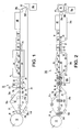
- Fig. 1 is a schematic view of an embodiment of a system for performing a method of manufacturing and finishing a web product;
- Fig. 2 is a schematic view of an alternative embodiment of a system for performing a method of manufacturing and finishing a web product;
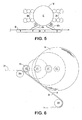
- Fig. 3 is an enlarged view of an optional calendering station of the system taken at area III in Fig. 1;
- Fig. 4 illustrates an alternative calendering station embodiment in which a calender roll is shown pivoted away from a conveyor while a vacuum transport conveyor simultaneously pivots toward the conveyor during thread-up of the web product;
- Fig. 5 illustrates an alternative printer station embodiment to the' serial printer arrangement at area V of Fig. 1; and
- Fig. 6 is an enlarged view of an optional parent roll assembly taken at area VI in Fig. 2 illustrating a parent roll being selectively formed.
- Detailed reference will now be made in which examples embodying the present invention are shown. Repeat use of reference characters is intended to represent same or analogous features or elements of the invention.
- The drawings and detailed description provide a full and detailed written description of the invention and the manner and process of making and using it so as to enable one skilled in the pertinent art to make and use it. The drawings and detailed description also provide the best mode of carrying out the invention. However, the examples set forth herein are provided by way of explanation of the invention and are not meant as limitations of the invention. The present invention thus includes modifications and variations of the following examples as come within the scope of the appended claims and their equivalents.
- As broadly embodied in the Figures, a web product system for manufacturing, directly forming and finishing a web is provided. In general, the
system 10 is configured to facilitate continuous support and movement of web W, which is discussed in detail herein. - As Fig. 1 illustrates, the
system 10 may include a paper-forming apparatus or adryer 12 such as a Yankee or through-air dryer, and a conveyance system such as a pick-up orfirst conveyor 14 and a second ordelivery conveyor 24, which cooperate to pass the web W from thedryer 12 in a direction of a folding orwinding station 48.System 10 may include a coater or plurality ofcoaters 18a-d; a plurality ofcarrier rolls 20a-f; an s-wrap reel orshear inducing element 22; a calendering station such ascalender roll 28 andopposing roll 30; an embossing station such aspattern roll 32 andbacking roll 34; a web attraction device such as avacuum box 36; a printer station including a plurality ofprinters 38 for multi-color printing; aperforator 44; a slitter or severingdevice 45; agluing station 46; afolding board 47 for producing multiple plies from a single sheet;station 48 for the finished web product, which may be an interfolder for folded products, a turret winder or surface winder to wind-up consumer-diameter "logs" for subsequent cutting into consumer-length for rolled products; and a pulper 50. The foregoing elements and stations and their operation are discussed in greater detail below. - While Fig. 1 illustrates all of the foregoing elements and stations, the
system 10 can be configured with any combination or all of the described elements and stations. Moreover, the exemplary elements and stations may be arranged other than as shown. For instance,printers 38 may be disposed upstream ofpattern roll 32 andbacking roll 34. Further, various quantities of elements may be disposed at various points along thesystem 10; e.g., another coater (not shown) may be disposedproximate folder 48. Furthermore, additional pulpers such aspulper 50b (Fig. 2) may be disposed at various open draws D insystem 10, for example, to facilitate cleaning or maintenance operations. - With more particular reference to Fig. 1, the optional pick-up
conveyor 14 is disposed adjacent thedryer 12 to pick up the formed and dried web W, which can be any type of formed web, such as a creped paper web or an UCTAD web. At least one way in whichconveyor 14 can pick-up web W is by a pick-up or transferroll 16, which may be configured with a vacuum. By way of example, vacuum-equippedroll 16 can attract web W fromdryer 12 across an open draw to theconveyor 14. However, the invention contemplates other pick-up/transfer arrangements such as direct contact betweendryer 12 or a dryer fabric (not shown) andconveyor 14. - Fig. 1 further illustrates that after pick-up
conveyor 14 picks up the web W, web W is continuously transferred downstream ofdryer 12 to be coated bycoaters 18a-d. It is to be noted that in addition tocoaters 18a-d, a plurality of other coaters may be disposed throughoutsystem 10 to coat the web W with a plurality of coatings. At least one of the coaters may be a roller and any of the coaters may be configured to coat the web W, theconveyors conveyors - Fig. 1 indicates that a number of other converting steps may be performed on the web W as it continuously advances on the pick-up
conveyor 14 to thedelivery conveyor 24. For instance, the coated web W can be subjected to a s-wrap or shear inducingelement 22 to create shear forces on web W to increase its softness. Other converting steps may include conveying the web W through at least one calendering nip N formed bycalender roll 28 and opposingroll 30 to impart a desired thickness or caliper to the web W. Optionally, thecalender roll 28 is a smooth steel roll and the opposingroll 30 is a resilient rubber roll to evenly calender the web W. Moreover, a plurality of calendering stations (e.g., calendar 28' and roll 30') may be provided according to Fig. 1. - If desired, web W may proceed continuously from the calendering station to an embossing station, which may include
pattern roll 32, also referred to as an embossing roll, and backing roll 34 that form an embossing nip N'. Embossing is a well-known mechanism to increase sheet caliper, and it also provides an additional benefit by "spot embossing" or imparting a decorative pattern to a tissue product, not further described. - After printing and embossing web W, Fig. 1 further indicates that a web attraction device such as
vacuum box 36 may be disposed alongsystem 10 to maintain web W againstconveyor 24 to allow printing on one side and then the web W is continuously advanced to aperforator 44 where web W is perforated as known to those in the art. By way of example, the web W can be perforated laterally prior to interfolding or winding. - Severing
device 45 is co-operable withperforator 44 to sever the perforated web W into various lengths. The severed web W will proceed to station 48 to be interfolded into folded products or wound on a winder into a rolled product to be subsequently cut into consumer product lengths and packaged, for example, by a turret-type assembly, an example of which is disclosed inU.S. Pat. No. 6,270,034 to Kury et al. - In the event of a broken web W', pulper 50a is disposed to receive the broken web W' to permit the remaining web W to continuously advance. One example of an operation of
system 10 is that web W is threaded-up (directed alongconveyor 24 fromdryer 12 to winder 48) until web W reaches pulper 50a. As web W is satisfactorily "flowing" alongconveyor 24, any and all of the foregoing finishing stations and elements are applied to web W as desired. In the event of a broken web W', thesystem 10 continues to operate uninterrupted by blowing the broken web W', for example, by air or water jets (not shown) off theconveyor 24 into pulper 50a. Simultaneously, an adversely affected log (not shown) is removed fromwinder 48 and rejected while a new core (not shown) is supplied towinder 48. Also concurrently, a new supply of unbroken web W continues flowing alongsystem 10 for wind-up on the new core atstation 48. - In some ways similar to Fig. 1, Fig. 2 also illustrates continuous support of web W. However, the
exemplary system 110 of Fig. 2 further includes, for example, threeconveyors vacuum boxes 36, static induction devices (not shown), and blowboxes 37 to continuously support the web W across various open draws D. - Advantageously,
separate conveyors calender 28, for example, the web is made thinner as it passes through the nip N. To ensure the same amount of web or web mass flows towardsprinting station 38, the speed of stand-alone conveyor 24b must and can be increased to maintain an overall constant speed ofsystem 10. In this inventive arrangement,boxes conveyors - Fig. 2 finally illustrates an
optional parent roll 54, discussed in greater detail in Fig. 6 below, which may be desirable if the web W requires coating and calendering, for instance, but winding or folding into an end-product are desired at a remote facility. - Fig. 3 shows
calender roll 28 cooperating with opposingroll 30 to form nip N through which the continuously advancing web W is conveyed byconveyor 24 to impart a desired caliper to the web W. Also, Fig. 3 illustrates continuous support of web W through the calendering run by twosections delivery conveyor 24 as web W passes through nip N. Web W may otherwise be continuously supported insystem 10 by a fabric conveyor, a foil, a vacuum shoe, an adjustable vacuum transport conveyor or combinations of the foregoing to support the web W at the standard web processing speed as described in the foregoing embodiment. - Fig. 4 shows an alternative to the exemplary embodiment of Fig. 3 in which calender roll 28 is attached to a
pivot mechanism 29 if it is desired to thread-up web W without subjecting web W to the calendering nip N. In this example, avacuum transport conveyor 31 may be pivoted towardconveyor 24 in order to thread web W across an area of the nip N before bringing on thecalendar roll 28. - Fig. 5 illustrates an alternative printing station to the serial arrangements of Figs. 1 and 2. In either embodiment, however,
printers 38 can be configured to print the web W with multiple colors. It is to be noted that although Figs. 1, 2 and 5 illustrate four color printing by fourprinters 38, any number of printer elements are envisioned by the invention. - With more specific reference to Fig. 5, a
delivery conveyor 24 is configured with vacuum to hold web W to theconveyor 24. If printing is desired, web W is directed away fromdelivery conveyor 24 bybypass conveyor 42a and ontoprinter roll 40 for multiple color printing on one or both sides of web W byprinters 38. Also indicated above, web W is always continuously supported and moved byconveyor 24,bypass conveyors 42a, b andprinter roll 40. - Fig. 6 shows in detail the selective formation of a
parent roll 54.System 10 may include this option to wind up web W into theparent roll 54 for subsequent processing into consumer-size logs and a final product if it is desired to bypasswinder 48. - Figs. 1-5 also illustrate a method of operation of the invention in which a rolled paper web product may be manufactured and finished without requiring a parent roll reeling step and an unwinding step. The method includes depositing an aqueous suspension of papermaking fibers onto an endless forming fabric to form a wet web W. The wet web W is transferred to a
dryer 12 for drying. If desired, the wet web W may be transferred from a forming fabric to an uncreped through-air dryer (UCTAD) to be dried and then rush-transferred from thedryer 12 at an UCTAD operating speed toconveyor 14 wherein the rush-transferred web W defines a molded web. The UCTAD web W can then be processed at various calendering stations. - Alternatively, the exemplary method may include creping the dried web W from the
dryer 12. Creped web W is continuously creped, advanced and transferred from thedryer 12 to afirst conveyor 14 in a similar manner described in the foregoing exemplary system. Additionally, it should be noted thatfirst conveyor 14 may receive the web W such as byvacuum roll 16, or by direct contact, gravity or the like, and thenfirst conveyor 14 guides the web W towardsecond conveyor 24. - Drying, picking up, and transferring web W may cause the width of the transferred web W to undesirably narrow. Accordingly, the disclosed method contemplates laterally spreading the web W by a
vacuum 36,blow box 37, spreader bar (not shown), Mount Hope roll (not shown) or any combinations of the foregoing as the web W passes between first andsecond conveyors vacuum box 36 can be configured proximate theconveyor 24 to pull or spread web W to a desired width. After spreading the web W, it is continuously advanced toward the various converting stations as seen in the Figures and previously described. - According to another aspect of the disclosed method, at least one
other pulper 50b may be disposed at any point between thefirst conveyor 14 and the severingdevice 45. As described above and seen particularly in Fig. 2,pulper 50b may be disposed proximate the open draw D to receive a broken portion of web W, while the remaining web W continuously moves in the direction of thewinder 48. This alternative exemplary arrangement may couple the generally slower converting processes to the generally faster tissue machine to thereby increase efficiencies of the overall manufacturing and finishing processes as described herein. - The method may also include the step of finishing web W by gluing or otherwise attaching web W to a core (not shown). Optionally, the glue or adhesive can be applied by the gluing
device 46 to attach the sheet to the core prior to the start of the winding step. The web W and core can then be rolled into a paper or other web product. If web W proceeds directly towinder 48, the rolled web product may have a diameter of from about 3.5 inches to about 6.5 inches, for example, for a consumer. - It will be apparent to those skilled in the art that various modifications and variations can be made in the present invention without departing from the scope and spirit of the invention, for example, specific shapes of various elements of the illustrated embodiments may be altered to suit particular web formation applications. It is intended that the present invention therefore include such modifications and variations as come within the scope of the appended claims and their equivalents.
Claims (7)
- A method for manufacturing and finishing an uncreped through-air dried web product from an aqueous suspension of fibers forming an endless wet web on a forming fabric, the method comprising the steps of:a) transferring the dried web from the dryer to a conveyor, the dryer and the conveyor configured to cooperate at substantially a single operating speed;b) continuously advancing the web on the conveyor, the conveyor configured to substantially support the web during a converting process;c) converting the web in the converting process;d) perforating the web with a perforator; ande) severing the perforated web with a severing device disposed proximate the perforator to form a finished web product.
- The method as in claim 1, wherein the converting step is selected from the group consisting of a calendering step, an embossing step, a printing step, and combinations thereof.
- The method as in claim 2, wherein the calendering step is performed by a calender roll and an opposing roll.
- The method as in claim 2, wherein the embossing step is performed by a pattern roll and a backing roll.
- The method of any preceding claim, further comprising the substep of continuously coating the web with a coater.
- The method of claim 5, wherein the coater is a coating roller.
- The method of claim 5, wherein the coater is a plurality of coaters configured to coat the web with a plurality of coatings.
Applications Claiming Priority (2)
| Application Number | Priority Date | Filing Date | Title |
|---|---|---|---|
| US10/025,382 US6740200B2 (en) | 2001-12-19 | 2001-12-19 | Methods and system for manufacturing and finishing web products at high speed without reeling and unwinding |
| EP02786761A EP1456465B1 (en) | 2001-12-19 | 2002-11-20 | Method for manufacturing and finishing web products at high speed without reeling and unwinding |
Related Parent Applications (1)
| Application Number | Title | Priority Date | Filing Date |
|---|---|---|---|
| EP02786761A Division EP1456465B1 (en) | 2001-12-19 | 2002-11-20 | Method for manufacturing and finishing web products at high speed without reeling and unwinding |
Publications (1)
| Publication Number | Publication Date |
|---|---|
| EP1816257A1 true EP1816257A1 (en) | 2007-08-08 |
Family
ID=21825703
Family Applications (3)
| Application Number | Title | Priority Date | Filing Date |
|---|---|---|---|
| EP02786761A Expired - Lifetime EP1456465B1 (en) | 2001-12-19 | 2002-11-20 | Method for manufacturing and finishing web products at high speed without reeling and unwinding |
| EP08011138A Expired - Lifetime EP1975315B1 (en) | 2001-12-19 | 2002-11-20 | System for manufacturing a web product |
| EP07008937A Withdrawn EP1816257A1 (en) | 2001-12-19 | 2002-11-20 | Method for manufacturing and finishing an uncreped through-air dried web |
Family Applications Before (2)
| Application Number | Title | Priority Date | Filing Date |
|---|---|---|---|
| EP02786761A Expired - Lifetime EP1456465B1 (en) | 2001-12-19 | 2002-11-20 | Method for manufacturing and finishing web products at high speed without reeling and unwinding |
| EP08011138A Expired - Lifetime EP1975315B1 (en) | 2001-12-19 | 2002-11-20 | System for manufacturing a web product |
Country Status (10)
| Country | Link |
|---|---|
| US (1) | US6740200B2 (en) |
| EP (3) | EP1456465B1 (en) |
| JP (1) | JP2005513295A (en) |
| KR (1) | KR100982633B1 (en) |
| AU (1) | AU2002350230C1 (en) |
| CA (1) | CA2469113C (en) |
| DE (1) | DE60228756D1 (en) |
| MX (1) | MXPA04005244A (en) |
| TW (1) | TWI242532B (en) |
| WO (1) | WO2003054293A1 (en) |
Cited By (1)
| Publication number | Priority date | Publication date | Assignee | Title |
|---|---|---|---|---|
| DE102011118609A1 (en) * | 2011-11-09 | 2013-05-16 | Hans Demanowski | Device for manufacturing printed web-like material e.g. paper in paper machine, for packaging purposes, has nozzles for printing web with image such that manufacturing of web from pulp and printing of web are carried out within same system |
Families Citing this family (34)
| Publication number | Priority date | Publication date | Assignee | Title |
|---|---|---|---|---|
| BR0117070A (en) * | 2001-06-06 | 2004-07-27 | Kemira Chemicals Oy | A method of making a multilayer pulp product comprising a interlayer loading and said product |
| US6743334B2 (en) * | 2002-06-11 | 2004-06-01 | Metso Paper Karlstad Aktiebolag (Ab) | Method and apparatus for making a tissue paper with improved tactile qualities while improving the reel-up process for a high bulk web |
| US6887348B2 (en) * | 2002-11-27 | 2005-05-03 | Kimberly-Clark Worldwide, Inc. | Rolled single ply tissue product having high bulk, softness, and firmness |
| TWI268972B (en) * | 2002-11-27 | 2006-12-21 | Kimberly Clark Co | Rolled tissue products having high bulk, softness, and firmness |
| FI117444B (en) * | 2004-06-24 | 2006-10-13 | Metso Paper Inc | Method for treating fiber web in one step following longitudinal cutting |
| DE102005037646A1 (en) * | 2005-08-05 | 2007-02-15 | Voith Patent Gmbh | Device for producing and / or treating a material web |
| US8038346B2 (en) * | 2005-09-26 | 2011-10-18 | Actherm Inc. | Detachable electronic pacifier thermometer |
| US20070131343A1 (en) * | 2005-12-14 | 2007-06-14 | Kimberly-Clark Worldwide, Inc. | Bonding of elastomeric substrate under stretched conditions |
| US7380747B2 (en) * | 2005-12-14 | 2008-06-03 | Kimberly-Clark Wolrdwide, Inc. | Through-roll profile unwind control system and method |
| JP4896551B2 (en) * | 2006-03-17 | 2012-03-14 | 王子ネピア株式会社 | Manufacturing method of tissue paper products in box |
| MX2010000739A (en) * | 2007-07-19 | 2010-04-07 | Luzenac America Inc | Silicone coatings, methods of making silicone coated articles and coated articles therefrom. |
| JP5331396B2 (en) * | 2008-07-08 | 2013-10-30 | 王子ネピア株式会社 | Toilet roll manufacturing method |
| JP2011127227A (en) * | 2009-12-15 | 2011-06-30 | Duplo Seiko Corp | Waste paper processing system |
| JP5855809B2 (en) * | 2009-12-28 | 2016-02-09 | 大王製紙株式会社 | Manufacturing method of tissue paper products |
| JP5855810B2 (en) * | 2009-12-28 | 2016-02-09 | 大王製紙株式会社 | Manufacturing method of tissue paper products |
| JP5833296B2 (en) * | 2010-03-26 | 2015-12-16 | 大王製紙株式会社 | Manufacturing method of tissue paper products |
| JP5833293B2 (en) * | 2010-03-26 | 2015-12-16 | 大王製紙株式会社 | Tissue paper manufacturing method |
| JP5833295B2 (en) * | 2010-03-26 | 2015-12-16 | 大王製紙株式会社 | Manufacturing method of tissue paper products |
| JP5833294B2 (en) * | 2010-03-26 | 2015-12-16 | 大王製紙株式会社 | Manufacturing method of tissue paper products |
| JP5833318B2 (en) * | 2011-02-07 | 2015-12-16 | 大王製紙株式会社 | Manufacturing method of tissue paper products |
| JP5833321B2 (en) * | 2011-03-01 | 2015-12-16 | 大王製紙株式会社 | Manufacturing method of tissue paper products |
| JP5844079B2 (en) * | 2011-06-30 | 2016-01-13 | 大王製紙株式会社 | Toilet roll manufacturing method |
| JP5931390B2 (en) * | 2011-09-29 | 2016-06-08 | 大王製紙株式会社 | Toilet roll manufacturing method |
| US9217225B2 (en) | 2012-02-28 | 2015-12-22 | Paprima Industries Inc. | Paper manufacturing |
| RU2656428C1 (en) * | 2014-06-12 | 2018-06-05 | Диопасс Спрл | Device for punching film |
| US9670616B2 (en) | 2014-12-11 | 2017-06-06 | Georgia-Pacific Consumer Products Lp | Active web spreading and stabilization shower |
| CN105084078B (en) * | 2015-08-28 | 2016-08-24 | 旌德县成宇纸管厂 | Integration paper tube coil paper processing unit (plant) |
| US10724173B2 (en) * | 2016-07-01 | 2020-07-28 | Mercer International, Inc. | Multi-density tissue towel products comprising high-aspect-ratio cellulose filaments |
| RU2655226C1 (en) * | 2016-12-02 | 2018-05-24 | Юрий Николаевич Комаров | Printing device with paper manufacturing unit |
| CN108149514B (en) * | 2017-12-20 | 2020-12-22 | 常德金德新材料科技股份有限公司 | Transfer paper and preparation method thereof |
| WO2019222165A1 (en) * | 2018-05-18 | 2019-11-21 | Brunn Air Systems, Inc. | Pneumatic core cleaning system cross-reference to related applications |
| MX2020012752A (en) * | 2018-06-27 | 2021-02-26 | Kimberly Clark Co | THROUGH AIR DRYING APPARATUS AND MANUFACTURING METHODS. |
| WO2021096379A1 (en) * | 2019-11-12 | 2021-05-20 | Юрий Николаевич КОМАРОВ | Printing device with a papermaking unit |
| WO2025252617A1 (en) * | 2024-06-03 | 2025-12-11 | Valmet Tissue Converting S.P.A. | A combined system or line for producing and converting a continuous web-like material, and method |
Citations (4)
| Publication number | Priority date | Publication date | Assignee | Title |
|---|---|---|---|---|
| DE1436601A1 (en) * | 1965-08-20 | 1969-04-03 | Goebel Gmbh Maschf | Method and device for preparing paper webs provided with watermarks for printing securities |
| EP0617164A1 (en) * | 1993-03-24 | 1994-09-28 | Kimberly-Clark Corporation | Method for making smooth uncreped throughdried sheets |
| EP1008690A2 (en) * | 1998-12-07 | 2000-06-14 | Voith Sulzer Papiertechnik Patent GmbH | Process and apparatus for making a paperweb |
| EP1063350A2 (en) * | 1999-06-24 | 2000-12-27 | Metsä-Serla Oyj | Method and apparatus for making patterned paper |
Family Cites Families (22)
| Publication number | Priority date | Publication date | Assignee | Title |
|---|---|---|---|---|
| US1315924A (en) * | 1919-09-09 | Production of heavy paper | ||
| US999375A (en) * | 1909-09-09 | 1911-08-01 | Scott Paper Co | Machine for manufacturing toilet-paper. |
| US1585977A (en) * | 1924-10-03 | 1926-05-25 | Edward M Hall | Machine for making membranous sheet wadding |
| US1842889A (en) * | 1928-09-01 | 1932-01-26 | Harrison R Williams | Paper machinery |
| US3756527A (en) * | 1970-10-29 | 1973-09-04 | Du Pont | Method of and apparatus for threading a web of plastic film onto a windup roll and winding it thereon |
| US4087319A (en) * | 1976-12-27 | 1978-05-02 | Beloit Corporation | Method of and means for sheet transfer to and embossing at a reeling station |
| FI60583C (en) | 1980-03-18 | 1982-02-10 | Valmet Oy | PROCEDURE FOR THE FRAMEWORK OF FRAMING SYSTEMS |
| US5129568A (en) * | 1990-01-22 | 1992-07-14 | Sequa Corporation | Off-line web finishing system |
| DE69127428T2 (en) * | 1990-12-19 | 1998-02-26 | Mitsubishi Paper Mills Ltd | Nonwoven and its manufacturing process |
| FI98387C (en) * | 1995-02-01 | 1997-06-10 | Valmet Corp | Process for making surface-treated paper, especially fine paper, and dry end for a paper machine |
| US5593545A (en) * | 1995-02-06 | 1997-01-14 | Kimberly-Clark Corporation | Method for making uncreped throughdried tissue products without an open draw |
| US5591309A (en) * | 1995-02-06 | 1997-01-07 | Kimberly-Clark Corporation | Papermaking machine for making uncreped throughdried tissue sheets |
| CA2144801C (en) | 1995-02-06 | 2008-01-15 | James Sigward Rugowski | Method for making uncreped throughdried tissue products without an open draw |
| CA2188074C (en) * | 1995-11-13 | 2000-12-05 | Dieter Kurth | Process for converting and printing on webs, and a printing machine for carrying out this process |
| US6076281A (en) * | 1997-03-03 | 2000-06-20 | Valmet Corporation | Web finishing section in a paper machine |
| US6355139B1 (en) * | 1997-04-16 | 2002-03-12 | Kimberly-Clark Worldwide, Inc. | Processed tissue webs |
| US6030496A (en) * | 1997-04-16 | 2000-02-29 | Kimberly-Clark Worldwide, Inc. | Making a web |
| BR9913896A (en) | 1998-09-22 | 2001-07-03 | Kimberly Clark Co | Process for the manufacture of an un-aged film laminate and an un-aged non-woven weave and products produced from it |
| US6270034B1 (en) | 1999-12-22 | 2001-08-07 | Kimberly-Clark Worldwide, Inc. | Rewinder mandrel system for winding paper |
| US6585855B2 (en) | 2000-05-12 | 2003-07-01 | Kimberly-Clark Worldwide, Inc. | Paper product having improved fuzz-on-edge property |
| DE10039040B4 (en) | 2000-08-10 | 2005-11-10 | Voith Paper Patent Gmbh | Method and device for producing paper rolls |
| DE60136742D1 (en) | 2000-11-08 | 2009-01-08 | Kimberly Clark Co | FOAM TREATMENT OF TISSUE PRODUCTS |
-
2001
- 2001-12-19 US US10/025,382 patent/US6740200B2/en not_active Expired - Lifetime
-
2002
- 2002-11-20 MX MXPA04005244A patent/MXPA04005244A/en active IP Right Grant
- 2002-11-20 AU AU2002350230A patent/AU2002350230C1/en not_active Ceased
- 2002-11-20 EP EP02786761A patent/EP1456465B1/en not_active Expired - Lifetime
- 2002-11-20 EP EP08011138A patent/EP1975315B1/en not_active Expired - Lifetime
- 2002-11-20 EP EP07008937A patent/EP1816257A1/en not_active Withdrawn
- 2002-11-20 JP JP2003554986A patent/JP2005513295A/en not_active Ceased
- 2002-11-20 CA CA2469113A patent/CA2469113C/en not_active Expired - Fee Related
- 2002-11-20 DE DE60228756T patent/DE60228756D1/en not_active Expired - Lifetime
- 2002-11-20 WO PCT/US2002/037459 patent/WO2003054293A1/en not_active Ceased
- 2002-11-20 KR KR1020047008383A patent/KR100982633B1/en not_active Expired - Fee Related
- 2002-12-12 TW TW091135922A patent/TWI242532B/en not_active IP Right Cessation
Patent Citations (4)
| Publication number | Priority date | Publication date | Assignee | Title |
|---|---|---|---|---|
| DE1436601A1 (en) * | 1965-08-20 | 1969-04-03 | Goebel Gmbh Maschf | Method and device for preparing paper webs provided with watermarks for printing securities |
| EP0617164A1 (en) * | 1993-03-24 | 1994-09-28 | Kimberly-Clark Corporation | Method for making smooth uncreped throughdried sheets |
| EP1008690A2 (en) * | 1998-12-07 | 2000-06-14 | Voith Sulzer Papiertechnik Patent GmbH | Process and apparatus for making a paperweb |
| EP1063350A2 (en) * | 1999-06-24 | 2000-12-27 | Metsä-Serla Oyj | Method and apparatus for making patterned paper |
Cited By (2)
| Publication number | Priority date | Publication date | Assignee | Title |
|---|---|---|---|---|
| DE102011118609A1 (en) * | 2011-11-09 | 2013-05-16 | Hans Demanowski | Device for manufacturing printed web-like material e.g. paper in paper machine, for packaging purposes, has nozzles for printing web with image such that manufacturing of web from pulp and printing of web are carried out within same system |
| DE102011118609B4 (en) * | 2011-11-09 | 2014-06-12 | Hans Demanowski | Apparatus and method for the production of printed web-shaped materials |
Also Published As
| Publication number | Publication date |
|---|---|
| MXPA04005244A (en) | 2004-10-11 |
| KR100982633B1 (en) | 2010-09-15 |
| DE60228756D1 (en) | 2008-10-16 |
| TW200305534A (en) | 2003-11-01 |
| EP1456465A1 (en) | 2004-09-15 |
| AU2002350230C1 (en) | 2008-10-02 |
| KR20040073446A (en) | 2004-08-19 |
| AU2002350230B2 (en) | 2008-05-08 |
| EP1975315A1 (en) | 2008-10-01 |
| EP1456465B1 (en) | 2008-09-03 |
| CA2469113A1 (en) | 2003-07-03 |
| CA2469113C (en) | 2011-09-27 |
| WO2003054293A1 (en) | 2003-07-03 |
| US20030113457A1 (en) | 2003-06-19 |
| AU2002350230A1 (en) | 2003-07-09 |
| US6740200B2 (en) | 2004-05-25 |
| JP2005513295A (en) | 2005-05-12 |
| TWI242532B (en) | 2005-11-01 |
| EP1975315B1 (en) | 2011-08-03 |
Similar Documents
| Publication | Publication Date | Title |
|---|---|---|
| EP1975315B1 (en) | System for manufacturing a web product | |
| ITFI930109A1 (en) | REWINDER FOR THE PRODUCTION OF ROLLS OF TAPE MATERIAL ALTERNATIVELY WITH OR WITHOUT WINDING BODY | |
| EP1456466B1 (en) | Method and apparatus for transporting a sheet from a dryer to a reel | |
| EP1373113B1 (en) | Multi-reel apparatus in a paper machine | |
| JP3518867B2 (en) | Assembly for paper web coating line | |
| US6368459B1 (en) | Method and apparatus for coating a moving web of paper or board | |
| JP3404481B2 (en) | Rewinding device installed at the end of off-machine type paper processing process | |
| US5762284A (en) | Assembly for the unwinder end of an off-machine paper web handling line | |
| EP4477590B1 (en) | Method of applying adhesive in a slitter-winder and a slitter-winder comprising a system of applying adhesive | |
| EP4230793B1 (en) | Method and system of producing of fiber webs | |
| WO2025252617A1 (en) | A combined system or line for producing and converting a continuous web-like material, and method |
Legal Events
| Date | Code | Title | Description |
|---|---|---|---|
| PUAI | Public reference made under article 153(3) epc to a published international application that has entered the european phase |
Free format text: ORIGINAL CODE: 0009012 |
|
| AC | Divisional application: reference to earlier application |
Ref document number: 1456465 Country of ref document: EP Kind code of ref document: P |
|
| AK | Designated contracting states |
Kind code of ref document: A1 Designated state(s): DE FR GB IT |
|
| RIN1 | Information on inventor provided before grant (corrected) |
Inventor name: PIGSLEY, KENNETH A. Inventor name: GOERG, CHARLES H. Inventor name: BAGGOT, JAMES L. Inventor name: SEYMOUR, ROBERT J. Inventor name: CLARKE, ROBERT L. Inventor name: LEVALLEY, RANDALL J. Inventor name: WOJCIK, STEVEN J. Inventor name: HANSON, JOHN R. Inventor name: ISOM, E. KENT |
|
| 17P | Request for examination filed |
Effective date: 20071217 |
|
| 17Q | First examination report despatched |
Effective date: 20080114 |
|
| AKX | Designation fees paid |
Designated state(s): DE FR GB IT |
|
| GRAP | Despatch of communication of intention to grant a patent |
Free format text: ORIGINAL CODE: EPIDOSNIGR1 |
|
| STAA | Information on the status of an ep patent application or granted ep patent |
Free format text: STATUS: THE APPLICATION IS DEEMED TO BE WITHDRAWN |
|
| 18D | Application deemed to be withdrawn |
Effective date: 20100511 |