EP1815776A1 - Flüssigkeitsspender - Google Patents
Flüssigkeitsspender Download PDFInfo
- Publication number
- EP1815776A1 EP1815776A1 EP07101605A EP07101605A EP1815776A1 EP 1815776 A1 EP1815776 A1 EP 1815776A1 EP 07101605 A EP07101605 A EP 07101605A EP 07101605 A EP07101605 A EP 07101605A EP 1815776 A1 EP1815776 A1 EP 1815776A1
- Authority
- EP
- European Patent Office
- Prior art keywords
- reservoir
- pump
- liquid product
- housing
- dispenser
- Prior art date
- Legal status (The legal status is an assumption and is not a legal conclusion. Google has not performed a legal analysis and makes no representation as to the accuracy of the status listed.)
- Granted
Links
Images

Classifications
-
- A—HUMAN NECESSITIES
- A47—FURNITURE; DOMESTIC ARTICLES OR APPLIANCES; COFFEE MILLS; SPICE MILLS; SUCTION CLEANERS IN GENERAL
- A47K—SANITARY EQUIPMENT; ACCESSORIES THEREFOR, e.g. TOILET ACCESSORIES
- A47K5/00—Holders or dispensers for soap, toothpaste or the like
- A47K5/06—Dispensers for soap
- A47K5/12—Dispensers for soap for liquid or pasty soap
- A47K5/1202—Dispensers for soap for liquid or pasty soap dispensing dosed volume
- A47K5/1204—Dispensers for soap for liquid or pasty soap dispensing dosed volume by means of a rigid dispensing chamber and pistons
- A47K5/1207—Dispensing from the bottom of the dispenser with a vertical piston
-
- A—HUMAN NECESSITIES
- A47—FURNITURE; DOMESTIC ARTICLES OR APPLIANCES; COFFEE MILLS; SPICE MILLS; SUCTION CLEANERS IN GENERAL
- A47K—SANITARY EQUIPMENT; ACCESSORIES THEREFOR, e.g. TOILET ACCESSORIES
- A47K5/00—Holders or dispensers for soap, toothpaste or the like
- A47K5/06—Dispensers for soap
- A47K5/12—Dispensers for soap for liquid or pasty soap
- A47K5/1202—Dispensers for soap for liquid or pasty soap dispensing dosed volume
- A47K5/1204—Dispensers for soap for liquid or pasty soap dispensing dosed volume by means of a rigid dispensing chamber and pistons
Definitions
- the invention relates to a dispenser for dispensing a fluid product, comprising:
- Fluid product dispensers of the type described in the opening paragraph are well known, and are described inter alia in US 5,445,288 (Deb), for example.
- Such dispensers are, for example, employed in washrooms, toilets, kitchens, hospitals, surgeries, hair/beauty salons, workshops and factories.
- Such dispensers are mounted to a wall, often in the vicinity of a basin, bath, shower or toilet bowl; alternatively, such dispensers may be freestanding, and may be placed on a shelf, worktop or wash hand basin, or a trolley.
- the actuating means are typically operated by hand, arm or elbow so as to dispense a quantity of fluid product.
- this fluid product will be dispensed into the operator's hand, or onto a carrier such as a cloth, after which the fluid product is rubbed onto the skin, or is applied from said carrier onto a surface to be treated, such as a metal or ceramic surface to be cleaned, for example.
- the reservoir in such a dispenser is collapsible, and because the pump withdraws liquid product from the reservoir without an air return (or substantial flow of other gas) back into the reservoir, the reservoir will steadily contract in upon itself as more and more of the liquid product is withdrawn by the pump. Such contraction tends to push liquid product out of the reservoir, helping to ensure that the reservoir is substantially emptied before it has to be replenished.
- a certain amount of liquid product nevertheless tends to get trapped in the reservoir, particularly along folds, seams and/or gussets that may be present in the reservoir, or in internal corners; such product is essentially wasted, since it is discarded with the old reservoir once a new reservoir is loaded into the housing.
- the quantity of liquid product wasted in this manner depends inter alia on the viscosity of the liquid product.
- Tensioning the reservoir in the manner according to the invention basically amounts to a constant attempt to negate the bulging of the reservoir. Since such bulging is caused by the act of (partially) filling an empty reservoir that is relatively flat to start off with, a constant attempt to negate this bulging thus amounts to a constant attempt to revert the reservoir to flatness and emptiness.
- the tensioning means in the housing according to the invention actively squeeze liquid product out of the reservoir, rather than just passively relying on gravity to cause as much liquid product as possible to migrate toward the pump.
- the tensioning means comprise suspending means for suspending the reservoir by a first extremity so that it hangs under the force of gravity, the pump being attached to a second extremity of the reservoir located opposite the first extremity. Because the reservoir is hung up in the housing - rather than, for example, sitting on a retaining shelf - the weight of the reservoir and its contents apply a tensioning force to the reservoir along the vertical direction (second direction), thus serving to counteract the (net) outward bulging of the reservoir in the horizontal direction (first direction).
- the suspending means comprise a drum that can be rotated about a substantially horizontal axis.
- the drum is rotationally/torsionally biased (e.g. using a spiral spring, elastic belt, etc.) in a first rotational sense, and the top of the reservoir is hung on the drum in such a manner that the weight of the reservoir (+ liquid product within) exerts a moment on the drum in a second rotational sense opposite to the first rotational sense.
- a thick soap solution comprising a suspended granulate solid
- commercially available examples of such a solution/suspension include Deb Swarfega TM , Stockhausen STOKO Solopol TM and CWS Abrasiva TM .
- the viscosity of this (tixotropic) solution/suspension was measured to be of the order of 10 5 centipoise in static measurements, and of the order of 4 x 10 3 centipoise in dynamic measurements.
- the employed reservoir was a plastic foil bag having two major opposing flat surfaces, which were sealed together at the head and foot and were joined at the sides by foil sheet parts with a central longitudinal folding seam; in this manner, the reservoir could collapse flat in a concertina-like fashion.
- This reservoir was suspended from a drum arrangement as set forth in the preceding paragraph. It was observed in this instance that as little as 0.9-2% of the initial load of viscous liquid product got trapped in the reservoir, which represents an improvement of a factor of at least three (and, in many cases, a factor of eight or more) compared to the results obtained using a non-inventive dispenser (see above).
- the efficiency of the pump In general, in order to empty the reservoir to as great an extent as possible, the efficiency of the pump must be kept as high as possible. This means that, when the pump is actuated so as to dispense fluid, the liquid inlet valve must be tightly shut, so as to minimize migration of liquid product from the pump back into the reservoir.
- a build-up of granulates within the liquid inlet valve e.g. between a ball bearing / flap member / top hat member and a corresponding valve seat, or in the throat of a duckbill valve
- a build-up of granulates within the liquid inlet valve can prevent the valve from shutting properly, and this can result in the creation of a substantial dead volume upstream of the valve.
- the pump when the assembly of reservoir + pump is accommodated in the housing, the pump is located at the underside of the reservoir.
- a throat may be provided at (or proximal to) the lowest point of the reservoir, and this throat may be connected to the liquid inlet valve of the pump (see previous paragraph) using a duct; see, for example, the abovementioned US 5,732,853 (Bentfield).
- the distance H between the liquid inlet valve of the pump and the point at which the pump is attached to the reservoir is preferably kept as short as possible; for example, in the previous sentence, said duct is ideally kept as short as possible (without sacrificing practicality). In this manner, pressure loss in the head H is kept to a minimum, so that the ability of the pump to suck liquid product out of the reservoir is optimized. This helps achieve a further reduction in the amount of liquid product trapped in the reservoir.
- the actuating means comprise at least one of:
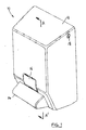
- Figure 1 renders a schematic perspective view of part of a dispenser 10 for dispensing a fluid product, in accordance with the prior art.
- Figure 1 shows a housing 12, which can be mounted to a wall of a washroom, for example.
- the housing 12 accommodates an assembly C that comprises a collapsible reservoir 20, for containing a liquid product, and an attached pump 22; these items are only visible in Figure 2, and will be discussed later in more detail.
- Actuating means 14 are movably connected to the housing 12, and can be actuated so as to operate said pump 22.
- an inspection window 16 which allows the amount of liquid product in the reservoir 20 to be seen from outside.
- An aperture 18 allows insertion of a tool with the aid of which the housing 12 can be unlocked and opened, allowing access to the assembly C (reservoir 20 + pump 22) located within.
- the housing 12 is made from any suitable rigid material, such as metal or a plastic, for example.
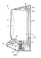
- Figure 2 renders a cross-sectional view of the subject of Figure 1, taken along the line A-A'.
- the reservoir 20 is now visible, and is here embodied as a flexible plastic container.
- the liquid product contained in the reservoir 20 may, for example, comprise soap, shower/bath gel, detergent, exfoliating scrub, or mixtures of (certain of) these products.
- a pump 22 is attached to the underside of the reservoir 20, so as to be able to draw liquid product from within the reservoir 20; since the pump 20 does not replace such withdrawn liquid product by air (or another gas), the reservoir 22 collapses inward as more and more liquid product is withdrawn therefrom.
- the pump 22 may be any suitable type of pump for the application in question, such as a liquid pump, spray pump or foam pump, for example, and may operate on the basis of a movable piston, bellows and/or membrane, for example. In operation, the pump 22 may directly dispense the liquid contained within the reservoir 20, or may first mix it with air to form a spray or foam, for example. In all cases, the pump 22 dispenses a fluid product from the nozzle 24.
- the actuating means 14 in this instance are hinged to the housing 12 via a hinge joint 26. This, together with the gap 28 below the actuating means 14, ensures that the actuating means 14 can be swung in and out of the housing 12.
- An arm 30 connects the actuating means 14 to the pump 22 in such a manner that, when the actuating means 14 are swung into the housing 12 about hinge point 26, arm 30 operates pump 22 so as to dispense a dose of fluid product through the nozzle 24.
- Biasing means such as spring 32, ensure that the actuating means 14 are urged back into their swung-out position when released.
- a user depresses the actuating means 14 using his hand palm, lower arm or elbow, for example, and collects the fluid product dispensed from the nozzle 24 in his hand or on a carrier (such as a cloth or tissue); in such applications, the nozzle 24 will generally face substantially downward.
- a carrier such as a cloth or tissue
- the pump 22 is removably mounted to a bracket 36 that protrudes from the back wall 34 of the housing 12.
- This back wall 34 can be provided with screw-holes, magnets, or other means for mounting it to a wall or other surface.
- a lug 38B protruding from the back wall 34 is a lug 38B, which grips a cooperating lug 38A; however, using a tool inserted through aperture 18, these two lugs 38A, 38B can be disengaged, allowing the housing 12 to be opened, e.g. so as to replace the reservoir 20 and/or pump 22 located inside (this may involve replacing either the entire assembly C as a whole, or replacing the reservoir 20 or pump 22 as parts).
- the bracket 36 not only supports the pump 22, but also indirectly supports the reservoir 20 from beneath.
- the reservoir 20 is therefore free to sag downward and bulge sideways. Such free sagging/bulging is conducive to the formation of folds and corners in which liquid product can be trapped as the reservoir 20 collapses in upon itself.
- Figure 3 renders a longitudinal cross-sectional view of a dispenser 10 according to an embodiment of the current invention.
- the dispenser 10 comprises a housing 12 for removably accommodating an assembly C comprising a collapsible reservoir 20 and a pump 22 that is connected to the reservoir 20.
- the current dispenser 10 comprises tensioning means T, whose operation will now be explained.
- the reservoir 20 in the current case is a plastic foil bag comprising two major opposing surfaces 20a that are sealed together at a first extremity (head) E1 and a second extremity (foot) E2, and are joined at the sides by an arrangement of foil sheet parts 20b with a central longitudinal folding seam 20c. Due to this construction, the reservoir 20 can collapse (substantially) flat in a concertina-like manner, whereby the parts 20a and 20b fold toward one another, hinging inward about the folding seam 20c.
- the reservoir 20 has a relatively flat form when empty and a relatively bulged form when at least partially filled, whereby bulging of the reservoir along a first direction (the outward arrows F) occurs as a result of corresponding contraction of the reservoir along a complimentary second direction (the inward arrows G).
- the plastic foil of the parts 20a and 20b may, for example, comprise polyethene (PE), polyamide (PA), polyethene terephthalate (PET), polypropene (PP), ethene-vinyl alcohol polymer (EVOH), or combinations (e.g. sandwiches/laminates) of these materials.
- the housing 12 comprises tensioning means T for applying an external force to the reservoir 20, which force is tensile along the second direction G.
- tensioning means T comprise suspending means 46 for suspending the reservoir 20 so that it hangs/dangles in the housing 12 under the force of gravity; this contrasts with the situation in Figure 2, in which the reservoir 20 is supported from beneath.
- Such hanging suspension of the reservoir 20 under its own weight applies a basic tensile force to the reservoir along the second direction G.
- the suspending means 46 take the form of a lug in the housing 12, which lug cooperates with (for example) a hook or a hole provided through the sealed extremities of the faces 20a of the bag 20.
- the skilled artisan could also easily conceive other suspending means 46 for suspending the reservoir 20, e.g. using clamping jaws, Velcro, adhesive tape, etc.
- suspending the reservoir 20 along a line (or a distribution of points) has been observed to give more satisfactory results than suspending the reservoir 20 at a single point (or relatively confined area).
- the suspending means 46 are provided on the cylindrical surface of a drum 40 that can be rotated about a substantially horizontal axis; in the drawing, the drum 40 is fitted on a substantially horizontal axle 42 provided at one end of an arm 44 that extends outward from the back wall 34 of the housing 12.
- This drum 40 is rotationally/torsionally biased about the axle 42 (using biasing means that have not been depicted in the figure, but that may comprise a spiral spring or elastic belt, for example) such that the drum wants to roll in the direction of the arrow H (first rotational sense), which is opposite to the moment (in the second rotational sense) exerted on the drum 42 by the weight of the reservoir 20 (+ liquid product within).
- biasing means that have not been depicted in the figure, but that may comprise a spiral spring or elastic belt, for example
- a collar 21a providing flow access to the inside of the reservoir 20.
- the pump 22 is attached to the reservoir 20 at this point (e.g. by clamping) so that an inlet duct 21b of the pump 22 fits into the collar 21a (see, for example, the construction set forth for this purpose in the abovementioned US 5,732,853 (Bentfield)).
- a non-return liquid inlet valve 23 for admitting liquid product into the pump 22 from the reservoir 20, the influx of liquid product through the valve 23 occurring along a flow axis I.
- clamping means 13 provided as part of the housing 12, the pump 22 is held/postured in such a manner that the flow axis I is substantially horizontal.
- the inventor has observed that, in the case of relatively viscous liquid products (e.g. products with a viscosity in the range 10 3 -10 5 centipoise: see above), the distance H between the liquid inlet valve 23 of the pump 22 and the point 21a at which the pump 22 is attached to the reservoir 20 is preferably kept as short as possible; in the current case, this implies that the inlet duct 21b should have a minimum (practicable) length. In this manner, pressure loss in the head H is kept to a minimum, so that the ability of the pump 22 to suck liquid product out of the reservoir 20 is optimized.
- relatively viscous liquid products e.g. products with a viscosity in the range 10 3 -10 5 centipoise: see above
- the distance H between the liquid inlet valve 23 of the pump 22 and the point 21a at which the pump 22 is attached to the reservoir 20 is preferably kept as short as possible; in the current case, this implies that the inlet duct 21b should have a minimum (practicable)
- the pump 22 in Figure 3 may also be tilted upward from horizontal. If one decides to use the pump 22 at such an above-horizontal angle, then one should generally ensure that:
- the actuating means 14 merely comprise a cap on the pump 22, which cap can be operated by hand.
- more elaborate actuating means can also be employed as an alternative to this simple arrangement, as set forth above.
- a further embodiment of a dispenser 10 according to the present invention is identical to that set forth in Embodiment 1 above, except as regards certain details of the tensioning means T.
- the drum 40 instead of rotationally biasing the drum 40, it can instead be used as a rotating pulley or a static sliding guide, and a spring or hanging counterweight (neither of which is depicted) can be used to tension the extremity E1 of the reservoir over this pulley/guide.
- the reservoir 20 instead of using a drum 40, the reservoir 20 can be hung from a spring or other resilient member (not depicted), which will pull the reservoir 20 upward as it becomes lighter (due to removal of liquid product therefrom).
Landscapes
- Health & Medical Sciences (AREA)
- Public Health (AREA)
- Containers And Packaging Bodies Having A Special Means To Remove Contents (AREA)
- Telephone Function (AREA)
- Jet Pumps And Other Pumps (AREA)
- Sampling And Sample Adjustment (AREA)
Priority Applications (2)
| Application Number | Priority Date | Filing Date | Title |
|---|---|---|---|
| EP07101605A EP1815776B1 (de) | 2006-02-07 | 2007-02-01 | Flüssigkeitsspender |
| PL07101605T PL1815776T3 (pl) | 2006-02-07 | 2007-02-01 | Dozownik produktów płynnych |
Applications Claiming Priority (2)
| Application Number | Priority Date | Filing Date | Title |
|---|---|---|---|
| EP06075257 | 2006-02-07 | ||
| EP07101605A EP1815776B1 (de) | 2006-02-07 | 2007-02-01 | Flüssigkeitsspender |
Publications (2)
| Publication Number | Publication Date |
|---|---|
| EP1815776A1 true EP1815776A1 (de) | 2007-08-08 |
| EP1815776B1 EP1815776B1 (de) | 2009-04-15 |
Family
ID=38985140
Family Applications (1)
| Application Number | Title | Priority Date | Filing Date |
|---|---|---|---|
| EP07101605A Not-in-force EP1815776B1 (de) | 2006-02-07 | 2007-02-01 | Flüssigkeitsspender |
Country Status (6)
| Country | Link |
|---|---|
| US (1) | US20080023487A1 (de) |
| EP (1) | EP1815776B1 (de) |
| AT (1) | ATE428339T1 (de) |
| DE (1) | DE602007000867D1 (de) |
| ES (1) | ES2326046T3 (de) |
| PL (1) | PL1815776T3 (de) |
Families Citing this family (9)
| Publication number | Priority date | Publication date | Assignee | Title |
|---|---|---|---|---|
| EP2311752A1 (de) * | 2009-10-15 | 2011-04-20 | Enoitalia S.p.A | Behälter für Getränke, insbesondere Wein, des Bag-in-Box-Typs |
| WO2011133077A1 (en) * | 2010-04-22 | 2011-10-27 | Sca Hygiene Products Ab | Pump soap dispenser |
| US8550307B2 (en) * | 2011-03-31 | 2013-10-08 | Brightwell Dispensers Limited | Dispensing device with a disposable pump |
| US20140048562A1 (en) * | 2012-08-17 | 2014-02-20 | Meadwestvaco Corporation | Pump device and flow control system |
| WO2014065728A1 (en) * | 2012-10-25 | 2014-05-01 | Sca Hygiene Products Ab | Dispensing system with the means for detecting liquid level and a collapsible container for such a system. |
| US9045260B2 (en) * | 2013-03-05 | 2015-06-02 | The Coca-Cola Company | Beverage dispensing system |
| WO2015015896A1 (ja) * | 2013-07-30 | 2015-02-05 | 株式会社ジーシー | 印象材自動練和装置 |
| US10264926B2 (en) | 2015-02-04 | 2019-04-23 | Gojo Industries, Inc. | Collapsible liquid container, fluid dispenser for collapsible liquid container, and method for making collapsible liquid container |
| WO2017120635A1 (en) * | 2016-01-14 | 2017-07-20 | Filipovic Steve | Caulking gun |
Citations (4)
| Publication number | Priority date | Publication date | Assignee | Title |
|---|---|---|---|---|
| WO1993005693A1 (en) * | 1991-09-13 | 1993-04-01 | Appor Limited | Containers and dispensers for the contents thereof |
| FR2701646A1 (fr) | 1993-02-19 | 1994-08-26 | Provendi Sa | Distributeur de produits liquides ou pâteux à commande électromagnétique. |
| US5445288A (en) | 1994-04-05 | 1995-08-29 | Sprintvest Corporation Nv | Liquid dispenser for dispensing foam |
| US5732853A (en) | 1992-11-03 | 1998-03-31 | Bentfield Europe B.V. | Dosing unit comprising a dispensing device and a container bag unit |
Family Cites Families (32)
| Publication number | Priority date | Publication date | Assignee | Title |
|---|---|---|---|---|
| US2717722A (en) * | 1955-09-13 | Dispenser for material in collapsible | ||
| US1436241A (en) * | 1921-06-20 | 1922-11-21 | Harvey H Davis | Reel for toy balloons |
| US2206985A (en) * | 1936-12-02 | 1940-07-09 | Owens Illinois Glass Co | Dispensing receptacle |
| US2678144A (en) * | 1948-08-27 | 1954-05-11 | Fred E Holt | Collapsible tube squeezing device |
| US2622768A (en) * | 1951-01-11 | 1952-12-23 | Merrel E Hatcher | Tooth paste dispenser having brush operated slidable closure |
| US3224706A (en) * | 1962-07-06 | 1965-12-21 | Gordon C Bastow | Reels |
| US3245635A (en) * | 1962-10-24 | 1966-04-12 | Rolaview Inc | Pull out display device |
| US3259276A (en) * | 1964-10-15 | 1966-07-05 | Harry H Chase | Holder-dispensing device for flexible and/or collapsible tubes |
| US3424422A (en) * | 1967-01-16 | 1969-01-28 | George Klangos | Adjustable support |
| US4765512A (en) * | 1979-05-22 | 1988-08-23 | Bull Jr Glen C | Self-dispensing spring biased thin film container |
| US4450982A (en) * | 1982-07-22 | 1984-05-29 | Ferreira Americo S | Toothpaste dispenser |
| US4690307A (en) * | 1982-09-29 | 1987-09-01 | Cole-Parmer Instrument Company | Dispensing system with slidable modules |
| DK529383A (da) * | 1982-12-03 | 1984-06-04 | Kimberly Clark Ltd | Apparat til afgivelse af flydende saebe |
| US4627551A (en) * | 1984-03-05 | 1986-12-09 | Oatey Co. | Dispenser system and method for dispensing putty-like material |
| US4850971A (en) * | 1986-05-06 | 1989-07-25 | Triangle Research And Development Corporation | Infusion method and means |
| GB8713392D0 (en) * | 1987-06-08 | 1987-07-15 | Flomat Ltd | Materials handling equipment |
| US4826099A (en) * | 1988-03-23 | 1989-05-02 | Johnson Rick J | Automatic cord reel for duck decoys |
| US4932562A (en) * | 1988-04-29 | 1990-06-12 | Triparte, Ltd. | Liquid dispensing system |
| GB8828774D0 (en) * | 1988-12-09 | 1989-01-18 | Flomat Ltd | Materials handling equipment |
| US5016779A (en) * | 1990-02-09 | 1991-05-21 | Nic Williamson | Apparatus for dispensing measured amounts of fluid from an open-ended pouch |
| CA2073256C (en) * | 1990-11-07 | 1999-01-26 | Shoji Uehira | Foam dispensing pump container |
| FI943851A7 (fi) * | 1992-02-25 | 1994-10-12 | Cambridge Consultants | Juoksevan aineen annostelulaitteisto |
| US5323932A (en) * | 1993-02-16 | 1994-06-28 | Bauman Michael G | Paste dispenser |
| US5775540A (en) * | 1995-03-01 | 1998-07-07 | Greenberg; Robert M. | Collapsible tube dispenser aid |
| CA2146102C (en) * | 1995-03-31 | 2000-07-25 | Hermann Ophardt | Bag fluid dispenser |
| US5765723A (en) * | 1996-08-05 | 1998-06-16 | A. R. Arena Products, Inc. | Bag evacuator |
| US5692868A (en) * | 1996-11-27 | 1997-12-02 | National Bulk Equipment, Inc. | System and method for unloading bulk material from a semi-rigid container |
| US6196420B1 (en) * | 1999-09-09 | 2001-03-06 | Nestec S.A. | Pumpless dispenser for viscous food products |
| US6247618B1 (en) * | 1999-10-22 | 2001-06-19 | Raymond A. Liberatore | Roll up tube dispenser with shell housing |
| US6669668B1 (en) * | 1999-11-05 | 2003-12-30 | Tandem Medical | Medication delivery pump |
| US6543651B2 (en) * | 2000-12-19 | 2003-04-08 | Kimberly-Clark Worldwide, Inc. | Self-contained viscous liquid dispenser |
| EP1266696A1 (de) * | 2001-06-13 | 2002-12-18 | Taplast S.p.A. | Balgpumpe zur Abgabe von Gasflüssigkeitmischungen |
-
2007
- 2007-02-01 EP EP07101605A patent/EP1815776B1/de not_active Not-in-force
- 2007-02-01 PL PL07101605T patent/PL1815776T3/pl unknown
- 2007-02-01 AT AT07101605T patent/ATE428339T1/de not_active IP Right Cessation
- 2007-02-01 ES ES07101605T patent/ES2326046T3/es active Active
- 2007-02-01 DE DE602007000867T patent/DE602007000867D1/de not_active Expired - Fee Related
- 2007-02-06 US US11/702,722 patent/US20080023487A1/en not_active Abandoned
Patent Citations (4)
| Publication number | Priority date | Publication date | Assignee | Title |
|---|---|---|---|---|
| WO1993005693A1 (en) * | 1991-09-13 | 1993-04-01 | Appor Limited | Containers and dispensers for the contents thereof |
| US5732853A (en) | 1992-11-03 | 1998-03-31 | Bentfield Europe B.V. | Dosing unit comprising a dispensing device and a container bag unit |
| FR2701646A1 (fr) | 1993-02-19 | 1994-08-26 | Provendi Sa | Distributeur de produits liquides ou pâteux à commande électromagnétique. |
| US5445288A (en) | 1994-04-05 | 1995-08-29 | Sprintvest Corporation Nv | Liquid dispenser for dispensing foam |
Also Published As
| Publication number | Publication date |
|---|---|
| US20080023487A1 (en) | 2008-01-31 |
| ATE428339T1 (de) | 2009-05-15 |
| PL1815776T3 (pl) | 2009-08-31 |
| DE602007000867D1 (de) | 2009-05-28 |
| ES2326046T3 (es) | 2009-09-29 |
| EP1815776B1 (de) | 2009-04-15 |
Similar Documents
| Publication | Publication Date | Title |
|---|---|---|
| EP1815776B1 (de) | Flüssigkeitsspender | |
| CN104754999B (zh) | 带有用于检测液位的装置的分配系统和用于这种系统的可收缩容器 | |
| US6729503B2 (en) | Liquid dispenser | |
| AU2002343237B2 (en) | Foam dispenser, housing and storage holder therefor | |
| US6234357B1 (en) | Multipurpose carrying system for dispensing viscous liquid products | |
| US20110127290A1 (en) | Dispensing Devices and Methods | |
| KR20030053532A (ko) | 배출 장치 | |
| US20140224893A1 (en) | Apparatus and method for moistening sanitary paper products | |
| JP2009505908A (ja) | 吊り下げ型液体分配器システムおよび装置 | |
| AU8231698A (en) | Valve means | |
| US20070261159A1 (en) | Utility container suspended from toilet paper dispenser | |
| US8631519B1 (en) | Toilet cleanser and deodorizer dispenser | |
| US7882985B2 (en) | Fluid dispenser with sanitary nozzle | |
| US6427875B1 (en) | Foam dispensing device | |
| US9565977B2 (en) | Dispensers and refill units having collapsible outlet tubes | |
| US20050127105A1 (en) | Method and apparatus to supply a viscous liquid | |
| WO2006122983A1 (en) | Pump for dispensing a fluid product and dispenser | |
| US10953429B2 (en) | System and method for dispenser | |
| JP3752591B2 (ja) | 容器装置 | |
| JP2025168337A (ja) | ディスペンサ、これに対する詰め替え容器の交換方法、及びバッファーユニット | |
| CA2806939A1 (en) | Refillable liquid dispenser toilet paper moistening device | |
| JP2004123193A (ja) | パウチ注出用補助治具 | |
| TW202537716A (zh) | 配料分配器的再填充裝置 | |
| US20180155179A1 (en) | Flowable Substance Refill Container |
Legal Events
| Date | Code | Title | Description |
|---|---|---|---|
| PUAI | Public reference made under article 153(3) epc to a published international application that has entered the european phase |
Free format text: ORIGINAL CODE: 0009012 |
|
| AK | Designated contracting states |
Kind code of ref document: A1 Designated state(s): AT BE BG CH CY CZ DE DK EE ES FI FR GB GR HU IE IS IT LI LT LU LV MC NL PL PT RO SE SI SK TR |
|
| AX | Request for extension of the european patent |
Extension state: AL BA HR MK YU |
|
| 17P | Request for examination filed |
Effective date: 20070830 |
|
| 17Q | First examination report despatched |
Effective date: 20071009 |
|
| AKX | Designation fees paid |
Designated state(s): AT BE BG CH CY CZ DE DK EE ES FI FR GB GR HU IE IS IT LI LT LU LV MC NL PL PT RO SE SI SK TR |
|
| GRAP | Despatch of communication of intention to grant a patent |
Free format text: ORIGINAL CODE: EPIDOSNIGR1 |
|
| GRAS | Grant fee paid |
Free format text: ORIGINAL CODE: EPIDOSNIGR3 |
|
| GRAA | (expected) grant |
Free format text: ORIGINAL CODE: 0009210 |
|
| AK | Designated contracting states |
Kind code of ref document: B1 Designated state(s): AT BE BG CH CY CZ DE DK EE ES FI FR GB GR HU IE IS IT LI LT LU LV MC NL PL PT RO SE SI SK TR |
|
| REG | Reference to a national code |
Ref country code: GB Ref legal event code: FG4D Ref country code: CH Ref legal event code: EP |
|
| REG | Reference to a national code |
Ref country code: IE Ref legal event code: FG4D |
|
| REF | Corresponds to: |
Ref document number: 602007000867 Country of ref document: DE Date of ref document: 20090528 Kind code of ref document: P |
|
| REG | Reference to a national code |
Ref country code: GR Ref legal event code: EP Ref document number: 20090401470 Country of ref document: GR |
|
| REG | Reference to a national code |
Ref country code: SE Ref legal event code: TRGR |
|
| REG | Reference to a national code |
Ref country code: PL Ref legal event code: T3 |
|
| REG | Reference to a national code |
Ref country code: ES Ref legal event code: FG2A Ref document number: 2326046 Country of ref document: ES Kind code of ref document: T3 |
|
| PG25 | Lapsed in a contracting state [announced via postgrant information from national office to epo] |
Ref country code: LT Free format text: LAPSE BECAUSE OF FAILURE TO SUBMIT A TRANSLATION OF THE DESCRIPTION OR TO PAY THE FEE WITHIN THE PRESCRIBED TIME-LIMIT Effective date: 20090415 Ref country code: AT Free format text: LAPSE BECAUSE OF FAILURE TO SUBMIT A TRANSLATION OF THE DESCRIPTION OR TO PAY THE FEE WITHIN THE PRESCRIBED TIME-LIMIT Effective date: 20090415 Ref country code: PT Free format text: LAPSE BECAUSE OF FAILURE TO SUBMIT A TRANSLATION OF THE DESCRIPTION OR TO PAY THE FEE WITHIN THE PRESCRIBED TIME-LIMIT Effective date: 20090915 Ref country code: FI Free format text: LAPSE BECAUSE OF FAILURE TO SUBMIT A TRANSLATION OF THE DESCRIPTION OR TO PAY THE FEE WITHIN THE PRESCRIBED TIME-LIMIT Effective date: 20090415 |
|
| PG25 | Lapsed in a contracting state [announced via postgrant information from national office to epo] |
Ref country code: LV Free format text: LAPSE BECAUSE OF FAILURE TO SUBMIT A TRANSLATION OF THE DESCRIPTION OR TO PAY THE FEE WITHIN THE PRESCRIBED TIME-LIMIT Effective date: 20090415 Ref country code: IS Free format text: LAPSE BECAUSE OF FAILURE TO SUBMIT A TRANSLATION OF THE DESCRIPTION OR TO PAY THE FEE WITHIN THE PRESCRIBED TIME-LIMIT Effective date: 20090815 Ref country code: SI Free format text: LAPSE BECAUSE OF FAILURE TO SUBMIT A TRANSLATION OF THE DESCRIPTION OR TO PAY THE FEE WITHIN THE PRESCRIBED TIME-LIMIT Effective date: 20090415 |
|
| PG25 | Lapsed in a contracting state [announced via postgrant information from national office to epo] |
Ref country code: DK Free format text: LAPSE BECAUSE OF FAILURE TO SUBMIT A TRANSLATION OF THE DESCRIPTION OR TO PAY THE FEE WITHIN THE PRESCRIBED TIME-LIMIT Effective date: 20090415 Ref country code: EE Free format text: LAPSE BECAUSE OF FAILURE TO SUBMIT A TRANSLATION OF THE DESCRIPTION OR TO PAY THE FEE WITHIN THE PRESCRIBED TIME-LIMIT Effective date: 20090415 Ref country code: CZ Free format text: LAPSE BECAUSE OF FAILURE TO SUBMIT A TRANSLATION OF THE DESCRIPTION OR TO PAY THE FEE WITHIN THE PRESCRIBED TIME-LIMIT Effective date: 20090415 Ref country code: RO Free format text: LAPSE BECAUSE OF FAILURE TO SUBMIT A TRANSLATION OF THE DESCRIPTION OR TO PAY THE FEE WITHIN THE PRESCRIBED TIME-LIMIT Effective date: 20090415 |
|
| PLBE | No opposition filed within time limit |
Free format text: ORIGINAL CODE: 0009261 |
|
| STAA | Information on the status of an ep patent application or granted ep patent |
Free format text: STATUS: NO OPPOSITION FILED WITHIN TIME LIMIT |
|
| PG25 | Lapsed in a contracting state [announced via postgrant information from national office to epo] |
Ref country code: BE Free format text: LAPSE BECAUSE OF FAILURE TO SUBMIT A TRANSLATION OF THE DESCRIPTION OR TO PAY THE FEE WITHIN THE PRESCRIBED TIME-LIMIT Effective date: 20090415 Ref country code: SK Free format text: LAPSE BECAUSE OF FAILURE TO SUBMIT A TRANSLATION OF THE DESCRIPTION OR TO PAY THE FEE WITHIN THE PRESCRIBED TIME-LIMIT Effective date: 20090415 |
|
| 26N | No opposition filed |
Effective date: 20100118 |
|
| PG25 | Lapsed in a contracting state [announced via postgrant information from national office to epo] |
Ref country code: BG Free format text: LAPSE BECAUSE OF FAILURE TO SUBMIT A TRANSLATION OF THE DESCRIPTION OR TO PAY THE FEE WITHIN THE PRESCRIBED TIME-LIMIT Effective date: 20090715 |
|
| REG | Reference to a national code |
Ref country code: NL Ref legal event code: V1 Effective date: 20100901 |
|
| PG25 | Lapsed in a contracting state [announced via postgrant information from national office to epo] |
Ref country code: MC Free format text: LAPSE BECAUSE OF NON-PAYMENT OF DUE FEES Effective date: 20100301 |
|
| REG | Reference to a national code |
Ref country code: FR Ref legal event code: ST Effective date: 20101029 |
|
| REG | Reference to a national code |
Ref country code: IE Ref legal event code: MM4A |
|
| PG25 | Lapsed in a contracting state [announced via postgrant information from national office to epo] |
Ref country code: CY Free format text: LAPSE BECAUSE OF FAILURE TO SUBMIT A TRANSLATION OF THE DESCRIPTION OR TO PAY THE FEE WITHIN THE PRESCRIBED TIME-LIMIT Effective date: 20100512 |
|
| PG25 | Lapsed in a contracting state [announced via postgrant information from national office to epo] |
Ref country code: FR Free format text: LAPSE BECAUSE OF NON-PAYMENT OF DUE FEES Effective date: 20100301 Ref country code: IE Free format text: LAPSE BECAUSE OF NON-PAYMENT OF DUE FEES Effective date: 20100201 Ref country code: NL Free format text: LAPSE BECAUSE OF NON-PAYMENT OF DUE FEES Effective date: 20100901 |
|
| PG25 | Lapsed in a contracting state [announced via postgrant information from national office to epo] |
Ref country code: DE Free format text: LAPSE BECAUSE OF NON-PAYMENT OF DUE FEES Effective date: 20100901 |
|
| REG | Reference to a national code |
Ref country code: ES Ref legal event code: FD2A Effective date: 20110308 |
|
| PG25 | Lapsed in a contracting state [announced via postgrant information from national office to epo] |
Ref country code: IT Free format text: LAPSE BECAUSE OF NON-PAYMENT OF DUE FEES Effective date: 20100201 |
|
| PG25 | Lapsed in a contracting state [announced via postgrant information from national office to epo] |
Ref country code: ES Free format text: LAPSE BECAUSE OF NON-PAYMENT OF DUE FEES Effective date: 20110307 |
|
| PGFP | Annual fee paid to national office [announced via postgrant information from national office to epo] |
Ref country code: GR Payment date: 20110527 Year of fee payment: 5 |
|
| PG25 | Lapsed in a contracting state [announced via postgrant information from national office to epo] |
Ref country code: ES Free format text: LAPSE BECAUSE OF NON-PAYMENT OF DUE FEES Effective date: 20100202 |
|
| PGFP | Annual fee paid to national office [announced via postgrant information from national office to epo] |
Ref country code: IT Payment date: 20110526 Year of fee payment: 5 |
|
| REG | Reference to a national code |
Ref country code: CH Ref legal event code: PL |
|
| PG25 | Lapsed in a contracting state [announced via postgrant information from national office to epo] |
Ref country code: LI Free format text: LAPSE BECAUSE OF NON-PAYMENT OF DUE FEES Effective date: 20110228 Ref country code: CH Free format text: LAPSE BECAUSE OF NON-PAYMENT OF DUE FEES Effective date: 20110228 |
|
| REG | Reference to a national code |
Ref country code: PL Ref legal event code: LAPE |
|
| PG25 | Lapsed in a contracting state [announced via postgrant information from national office to epo] |
Ref country code: PL Free format text: LAPSE BECAUSE OF NON-PAYMENT OF DUE FEES Effective date: 20100201 |
|
| PG25 | Lapsed in a contracting state [announced via postgrant information from national office to epo] |
Ref country code: LU Free format text: LAPSE BECAUSE OF NON-PAYMENT OF DUE FEES Effective date: 20100201 Ref country code: HU Free format text: LAPSE BECAUSE OF FAILURE TO SUBMIT A TRANSLATION OF THE DESCRIPTION OR TO PAY THE FEE WITHIN THE PRESCRIBED TIME-LIMIT Effective date: 20091016 |
|
| REG | Reference to a national code |
Ref country code: GR Ref legal event code: ML Ref document number: 20090401470 Country of ref document: GR Effective date: 20120905 |
|
| PG25 | Lapsed in a contracting state [announced via postgrant information from national office to epo] |
Ref country code: TR Free format text: LAPSE BECAUSE OF FAILURE TO SUBMIT A TRANSLATION OF THE DESCRIPTION OR TO PAY THE FEE WITHIN THE PRESCRIBED TIME-LIMIT Effective date: 20090415 |
|
| PG25 | Lapsed in a contracting state [announced via postgrant information from national office to epo] |
Ref country code: GR Free format text: LAPSE BECAUSE OF NON-PAYMENT OF DUE FEES Effective date: 20120905 Ref country code: IT Free format text: LAPSE BECAUSE OF NON-PAYMENT OF DUE FEES Effective date: 20120201 |
|
| PGFP | Annual fee paid to national office [announced via postgrant information from national office to epo] |
Ref country code: SE Payment date: 20130227 Year of fee payment: 7 |
|
| REG | Reference to a national code |
Ref country code: SE Ref legal event code: EUG |
|
| PG25 | Lapsed in a contracting state [announced via postgrant information from national office to epo] |
Ref country code: SE Free format text: LAPSE BECAUSE OF NON-PAYMENT OF DUE FEES Effective date: 20140202 |
|
| PGFP | Annual fee paid to national office [announced via postgrant information from national office to epo] |
Ref country code: GB Payment date: 20160226 Year of fee payment: 10 |
|
| GBPC | Gb: european patent ceased through non-payment of renewal fee |
Effective date: 20170201 |
|
| PG25 | Lapsed in a contracting state [announced via postgrant information from national office to epo] |
Ref country code: GB Free format text: LAPSE BECAUSE OF NON-PAYMENT OF DUE FEES Effective date: 20170201 |