EP1815768A1 - Closing- and damping device for a two-way opening drawer - Google Patents
Closing- and damping device for a two-way opening drawer Download PDFInfo
- Publication number
- EP1815768A1 EP1815768A1 EP06101292A EP06101292A EP1815768A1 EP 1815768 A1 EP1815768 A1 EP 1815768A1 EP 06101292 A EP06101292 A EP 06101292A EP 06101292 A EP06101292 A EP 06101292A EP 1815768 A1 EP1815768 A1 EP 1815768A1
- Authority
- EP
- European Patent Office
- Prior art keywords
- cam
- pull
- damping device
- sliding part
- pulling
- Prior art date
- Legal status (The legal status is an assumption and is not a legal conclusion. Google has not performed a legal analysis and makes no representation as to the accuracy of the status listed.)
- Granted
Links
Images


Classifications
-
- A—HUMAN NECESSITIES
- A47—FURNITURE; DOMESTIC ARTICLES OR APPLIANCES; COFFEE MILLS; SPICE MILLS; SUCTION CLEANERS IN GENERAL
- A47B—TABLES; DESKS; OFFICE FURNITURE; CABINETS; DRAWERS; GENERAL DETAILS OF FURNITURE
- A47B88/00—Drawers for tables, cabinets or like furniture; Guides for drawers
- A47B88/40—Sliding drawers; Slides or guides therefor
- A47B88/453—Actuated drawers
- A47B88/46—Actuated drawers operated by mechanically-stored energy, e.g. by springs
- A47B88/467—Actuated drawers operated by mechanically-stored energy, e.g. by springs self-closing
-
- A—HUMAN NECESSITIES
- A47—FURNITURE; DOMESTIC ARTICLES OR APPLIANCES; COFFEE MILLS; SPICE MILLS; SUCTION CLEANERS IN GENERAL
- A47B—TABLES; DESKS; OFFICE FURNITURE; CABINETS; DRAWERS; GENERAL DETAILS OF FURNITURE
- A47B88/00—Drawers for tables, cabinets or like furniture; Guides for drawers
- A47B88/40—Sliding drawers; Slides or guides therefor
- A47B88/403—Drawer slides being extractable on two or more sides of the cabinet
Definitions
- the present invention relates to a retraction and damping device for a pull-out on both sides pull-out element, in particular drawer, in a freestanding body, which is slidably mounted in the direction of withdrawal in linear guides, and which is equipped at the front end portions each with a cover with detachable Locking means are provided, by means of which the covers are respectively lockable on the pull-out end side of the pull-out or on the body.
- the object of the present invention is thus to provide a retracting and damping device for a pull-out element which can be pulled out on both sides, which retracts and damps an extension element inserted from both sides into the closed position.
- the solution of this object is achieved in that the retraction and damping device has a sliding transverse to the pull-out of the pull-out sliding part with a cam which is fixed to the body and spring means in a closed position can be pulled, and the cam interacts with curves on the Pull-out are attached, and which have in the closed position of the pull-out a recess, in which the cam on the sliding part in the closed position of the pull-out element is pressed by the spring means.
- the curve has a first curved path on both sides, along which the cam of the sliding part runs when the pull-out element pushes into the carcass.
- a pivotable tongue closing off the unused curved path is provided between first curved paths running away from the indentation on both sides.
- this tongue is avoided that when running the cam on the corresponding curved path lifting this cam can enter from the web.
- a further advantageous embodiment of the invention is that of the indentation, the curve on both sides has a second curved path along which the cam of the sliding part when pulling out the Ausziehimplantations from the body runs, which has a lower slope of the indentation than the first curved path, and which second curved path again opens into the first curved path. Due to the lower slope of this web is achieved that the tensioning of the spring means of the retraction and damping device with less force is possible.
- third cam tracks are attached to the outer region facing away from the indentation of the curve, which have a sloping shape towards the respective pull-out side of the pull-out element.
- the sliding part cooperates with a locking arrangement, by means of which the sliding part with the cam in the closed position opposite the closed position can be locked.
- the locking arrangement is provided with a pivotable from a locked position to an unlocked position latch which is controllable via a further curve path provided on the curve. This gives a simple structure of this arrangement.
- the sliding part is equipped with a cooperating with the spring means damping element, whereby an optimal operation is achieved.
- the spring means are mounted on both sides of the sliding part tension springs, and the damping element is a piston-cylinder unit, which is mounted between the two tension springs. This gives you optimal functionality.
- a further advantageous embodiment of the invention is that the curve consists of a plate, preferably of plastic, and that the cam tracks are milled into the plate tracks. This results in a simple method of production.
- the cam is designed as a roller rotatably mounted on an axis. This role can be unrolled on the tracks with little friction.
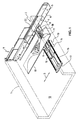
- the pull-out element 1 is shown in a spatial representation (with dotted lines), which has the shape of a drawer.
- This drawer is extendable along linear guides 2 in the direction of the double arrow 3 on both sides of a body, not shown.
- one part 4 of the linear guide 2 is attached to the drawer 1
- the other part 5 of the linear guide 2 is fixed to the body, not shown.
- This other part 5 of the linear guide has an angle section 6.
- the locking device 7 is shown, with which the rear cover, not shown, can be locked to the drawer 1.
- these locking devices 7 cause the cover on the extendable side is connected to the drawer, while the opposite cover is connected to the body.
- a rail 8 is fixed, in which the sliding part 9 is slidably mounted.
- the direction of displacement of this sliding part 9, represented by the double arrow 10, is perpendicular to the pull-out direction of the drawer and consequently to the double arrow 3.
- the sliding part 9 is equipped with a cam 11.
- a plate 13 is fixed, which is provided with a plurality of curved paths, as will be described in detail later.
- this plate 13 which consists of plastic, the curves are milled from the bottom seen, the plate then rests with the flat side on the bottom of the bottom 12 of the drawer.
- the curves already exhibiting molded plastic could be made and used.
- the sliding part 9 is provided with a bracket 14, on whose legs in each case a tension spring 15 and 16 is mounted.
- the other ends of the tension springs 15 and 16 are each mounted on one end of a transverse web 17, which is fixed to the end of the rail 8 facing away from the linear guide 2.
- the sliding part 9 is pulled with the cam 11 against the transverse web 17, the cam 11 is thereby pressed against the curve of the plate 13, as will be seen later in detail.
- a locking arrangement 18 is attached to the rail 8, which will also be described in detail later.
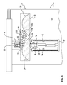
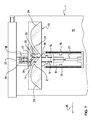
- a recess 19 is mounted in the plate 13 in the central region. From this recess 19 from each extending on both sides a first Curved track 20 and a second cam track 21.
- the drawer 1 is in the retracted position in the body.
- the plate 13 is thus symmetrical with respect to the cam 11, this means that the cam 11 is located in the recess 19 of the curves, that is, the sliding part 9 is in the retracted position, which is achieved by the tension springs 15 and 16.
- the latch 22 of the latch assembly 18 is in the unlocked state.
- the drawer 1 can now be fully extended, as shown in Fig. 5.
- the latch 22 which is latched in the slot 26 which is attached to the sliding part 9, the sliding part remains in the fully extended position.
- the springs 15 and 16 are fully cocked.
- the drawer 1 can now be pushed back against the retracted position in the direction of the arrow 25, as shown in Fig. 6.
- the sliding part 9 is still in the locked position.
- the cam 11 thus does not follow when pushing back the drawer 1 more of the second curved path 21, but enters the first curved path 20 a.
- the cam 11 has reached the first curved path 20, as shown in Fig. 6, the bolt 22 comes into the sphere of influence of the other curved path 23.
- the bolt 22 by the further curved path 23rd lifted and releases the slot 26.
- a pivotable tongue 28 is disposed between the first two cam tracks 20. This pivotable tongue 28 locks when inserting the drawer 1, the respectively not used cam track 20. This ensures a safe flow is achieved. In the fully retracted position, the situation is again reached, as has been shown in Fig. 2.
- the slope of the second curved path 21 seen from the recess 19 forth is less than the slope of the first curved path 20, also seen from the recess 19 ago. This ensures that when extending the drawer from the retracted position by the lower pitch of the second cam track 21, the force for tensioning the tension springs 15 and 16 is relatively low. As a result, the drawer 1 can be brought from the inserted to an extended position with little effort. As a result of the greater incline of the first curved track 20 as seen from the indentation 19, it is achieved that the retraction process for retracting the drawer 1 into the retracted position takes place with greater force. This ensures that the drawer 1 is pulled into the fully retracted position, caused by the tensile force of the tension springs 15 and 16 in cooperation with the sliding part 9 and the cam eleventh
- the sliding part 9 can be seen, which is equipped with the cam 11.
- the cam bears against the first curved path 20.
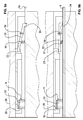
- the latch assembly 18 in which the latch 22 is pivotally supported about an axis 30.
- the sliding part 9 is in the locked position.
- the bolt 22 is thus outside the sphere of influence of the other cam track 23, the bolt 22 is pivoted about the compression spring 31 so that the bolt 22 in the slot 26 of the sliding part 9 engages.
- the cam 11 is formed as a roller 32 which is rotatably supported on a journal 33, which journal 33 is attached to the sliding part 9.
Abstract
Description
Die vorliegende Erfindung bezieht sich auf eine Einzieh- und Dämpfungseinrichtung für ein beidseitig ausziehbares Ausziehelement, insbesondere Schublade, in einem freistehenden Korpus, welches in Ausziehrichtung in Linearführungen verschiebbar gelagert ist, und welches an den stirnseitigen Endbereichen jeweils mit einer Abdeckung ausgestattet ist, die mit lösbaren Verriegelungseinrichtungen versehen sind, mittels welchen die Abdeckungen jeweils an der ausziehseitigen Stirnseite des Ausziehelementes beziehungsweise am Korpus verriegelbar sind.The present invention relates to a retraction and damping device for a pull-out on both sides pull-out element, in particular drawer, in a freestanding body, which is slidably mounted in the direction of withdrawal in linear guides, and which is equipped at the front end portions each with a cover with detachable Locking means are provided, by means of which the covers are respectively lockable on the pull-out end side of the pull-out or on the body.
Für einseitig aus einem Korpus ausziehbare Ausziehelemente, insbesondere Schubladen, sind verschiedenartige Einzieh- und Dämpfungseinrichtungen bekannt. Diese Einzieh- und Dämpfungseinrichtungen haben zum Ziel, dass beim Einschieben des Ausziehelementes der letzte Bereich des Einschiebeweges gesteuert erfolgt, so dass das Ausziehelement in die eingeschobene Stellung gezogen wird, wobei dieses Einziehen in gedämpfter Weise erfolgt. Mit diesen Einrichtungen wird vermieden, dass beispielsweise beim Einschieben des Ausziehelementes ein starker Schlag entsteht, was einen grossen Lärm verursacht. Mit derartigen Einrichtungen wird das Ausziehelement auf dem letzten Bereich des Einschubweges abgebremst und in gedämpfter Weise in die voll eingeschobene Position geführt.For one-sided extendable from a body pull-out elements, especially drawers, various retraction and damping devices are known. These retraction and damping devices have the goal that when inserting the Ausziehelementes the last portion of the insertion path is controlled, so that the pull-out is pulled into the inserted position, this retraction takes place in a subdued manner. With these devices it is avoided that, for example, when inserting the pull-out element a strong impact occurs, which causes a lot of noise. With such facilities, the pull-out is braked on the last region of the insertion path and performed in a damped manner in the fully inserted position.
Da bei beidseitig ausziehbaren Ausziehelementen in einem freistehenden Korpus der Verschiebeweg von der eingeschobenen Position in beide Richtungen ausgeführt wird, sind derartige bekannte Einzieh- und Dämpfungseinrichtungen für diese Art von Anwendung nicht in optimaler Weise geeignet. Diese Einzieh- und Dämpfungseinrichtungen müssten, ähnlich wie die Frontabdeckungen des beidseitig ausziehbaren Ausziehelementes, doppelt ausgeführt werden und jede Einzieh- und Dämpfungeinrichtung müsste zu- und abkoppelbar sein, damit eine beidseitige automatische Einziehung und Abdämpfung des Ausziehelementes gegen die eingeschobene Position hin erreichbar wäre.Since the displacement path from the retracted position is carried out in both directions in extractable elements extending on both sides in a freestanding body, such known retraction and damping devices are not optimally suited for this type of application. These retraction and damping devices would, like the front covers of both sides extendable pull-out element, be carried out twice and each retraction and damping device would have to be coupled and disconnected, so that a double-sided automatic recovery and damping of the pull-out element against the inserted position would be reached.
Die Aufgabe der vorliegenden Erfindung besteht somit darin, eine Einzieh- und Dämpfungseinrichtung für ein beidseitig ausziehbares Ausziehelement zu schaffen, das ein von beiden Seiten eingeschobenes Ausziehelement in die Schliessstellung einzieht und dämpft.The object of the present invention is thus to provide a retracting and damping device for a pull-out element which can be pulled out on both sides, which retracts and damps an extension element inserted from both sides into the closed position.
Erfindungsgemäss erfolgt die Lösung dieser Aufgabe dadurch, dass die Einzieh- und Dämpfungseinrichtung einen quer zur Ausziehrichtung des Ausziehelementes verschiebbaren Schiebeteil mit einem Nocken aufweist, welcher am Korpus befestigt ist und über Federmittel in eine Schliessstellung ziehbar ist, und der Nocken mit Kurven zusammenwirkt, die am Ausziehelement befestigt sind, und welche in der Schliessstellung des Ausziehelementes eine Einbuchtung aufweisen, in welche der Nocken über den Schiebeteil in der Schliessstellung des Ausziehelementes durch die Federmittel drückbar ist.According to the invention, the solution of this object is achieved in that the retraction and damping device has a sliding transverse to the pull-out of the pull-out sliding part with a cam which is fixed to the body and spring means in a closed position can be pulled, and the cam interacts with curves on the Pull-out are attached, and which have in the closed position of the pull-out a recess, in which the cam on the sliding part in the closed position of the pull-out element is pressed by the spring means.
Mit dieser einfach aufgebauten Einzieh- und Dämpfungseinrichtung werden die gewünschten Funktionen des Einziehens und Dämpfens für von beiden Seiten her eingeschobenen Ausziehelementen in optimaler Weise erfüllt.With this simply constructed retraction and damping device the desired functions of retraction and damping are met for inserted from both sides pull-out elements in an optimal way.
In vorteilhafter Weise weist von der Einbuchtung her die Kurve auf beide Seiten hin eine erste Kurvenbahn auf, entlang welcher der Nocken des Schiebeteils beim Einstossen des Ausziehelementes in den Korpus verläuft. Dadurch kann ein optimaler Bewegungsablauf beim Einziehvorgang des Ausziehelementes in den Korpus erreicht werden.Advantageously, from the indentation, the curve has a first curved path on both sides, along which the cam of the sliding part runs when the pull-out element pushes into the carcass. As a result, an optimal sequence of movements during the pulling-in process of the pull-out element into the body can be achieved.
In vorteilhafter Weise ist zwischen auf beide Seiten von der Einbuchtung her weglaufenden ersten Kurvenbahnen eine die nicht genutzte Kurvenbahn verschliessende schwenkbare Zunge angebracht. Durch diese Zunge wird vermieden, dass beim Entlanglaufen des Nockens an der entsprechenden Kurvenbahn ein Abheben dieses Nockens von der Bahn eintreten kann.
Eine weitere vorteilhafte Ausgestaltung der Erfindung besteht darin, dass von der Einbuchtung her die Kurve auf beide Seiten hin eine zweite Kurvenbahn aufweist, entlang welcher der Nocken des Schiebeteils beim Ausziehen des Ausziehelementes aus dem Korpus verläuft, welche von der Einbuchtung her eine geringere Steigung aufweist als die erste Kurvenbahn, und welche zweite Kurvenbahn wieder in die erste Kurvenbahn mündet. Durch die geringere Steigung dieser Bahn wird erreicht, dass das Spannen der Federmittel der Einzieh- und Dämpfungseinrichtung mit geringerer Kraft möglich wird.In an advantageous manner, a pivotable tongue closing off the unused curved path is provided between first curved paths running away from the indentation on both sides. By this tongue is avoided that when running the cam on the corresponding curved path lifting this cam can enter from the web.
A further advantageous embodiment of the invention is that of the indentation, the curve on both sides has a second curved path along which the cam of the sliding part when pulling out the Ausziehelementes from the body runs, which has a lower slope of the indentation than the first curved path, and which second curved path again opens into the first curved path. Due to the lower slope of this web is achieved that the tensioning of the spring means of the retraction and damping device with less force is possible.
In vorteilhafter Weise sind an den der Einbuchtung der Kurve abgewandten Aussenbereichen dritte Kurvenbahnen angebracht, welche gegen die jeweilige Ausziehseite des Ausziehelementes hin eine abfallende Form haben. Dadurch kann der Schiebeteil, wenn dieser im ausgezogenen Zustand des Ausziehelementes aus irgend einem Grund in die Schliessstellung zurückgezogen worden ist, wieder in die richtige Position gebracht werden, indem die Federn wieder gespannt werden.Advantageously, third cam tracks are attached to the outer region facing away from the indentation of the curve, which have a sloping shape towards the respective pull-out side of the pull-out element. As a result, the sliding part, if it has been withdrawn in the extended state of the pull-out element for some reason in the closed position, be brought back into the correct position by the springs are tensioned again.
In vorteilhafter Weise wirkt der Schiebeteil mit einer Verriegelungsanordnung zusammen, mittels welcher der Schiebeteil mit dem Nocken in der der Schliessstellung gegenüberliegenden voll ausgefahren Position verriegelbar ist. Mit dieser Anordnung wird vermieden, dass sich die Feder im voll ausgezogenen Zustand des Ausziehelements entspannt und diese beim Einschieben, bevor das selbständige Einziehen und Dämpfen beginnt, wieder gespannt werden muss.Advantageously, the sliding part cooperates with a locking arrangement, by means of which the sliding part with the cam in the closed position opposite the closed position can be locked. With this arrangement, it is avoided that the spring relaxed in the fully extended state of the pull-out and these must be re-tensioned during insertion, before the self-feeding and steaming begins.
In vorteilhafter Weise ist die Verriegelungsanordnung mit einem von einer verriegelten Position in eine entriegelte Position schwenkbaren Riegel versehen, der über eine weitere an der Kurve vorgesehenen Kurvenbahn steuerbar ist. Dadurch erhält man einen einfachen Aufbau dieser Anordnung.Advantageously, the locking arrangement is provided with a pivotable from a locked position to an unlocked position latch which is controllable via a further curve path provided on the curve. This gives a simple structure of this arrangement.
In vorteilhafter Weise ist der Schiebeteil mit einem mit den Federmitteln zusammenwirkenden Dämpfungselement ausgestattet, wodurch eine optimale Wirkungsweise erreicht wird.Advantageously, the sliding part is equipped with a cooperating with the spring means damping element, whereby an optimal operation is achieved.
In vorteilhafter Weise sind die Federmittel beidseitig am Schiebeteil angebrachte Zugfedern, und ist das Dämpfungselement eine Kolbenzylindereinheit, welche zwischen den beiden Zugfedern angebracht ist. Dadurch erhält man eine optimale Funktionsweise.Advantageously, the spring means are mounted on both sides of the sliding part tension springs, and the damping element is a piston-cylinder unit, which is mounted between the two tension springs. This gives you optimal functionality.
Eine weitere vorteilhafte Ausgestaltung der Erfindung besteht darin, dass die Kurve aus einer Platte besteht, vorzugsweise aus Kunststoff, und dass die Kurvenbahnen in die Platte eingefräste Bahnen sind. Dies ergibt eine einfache Herstellungsweise.A further advantageous embodiment of the invention is that the curve consists of a plate, preferably of plastic, and that the cam tracks are milled into the plate tracks. This results in a simple method of production.
In vorteilhafter Weise ist der Nocken als auf einer Achse drehbar angeordneten Rolle ausgebildet. Diese Rolle ist mit geringer Reibung auf den Bahnen abrollbar.Advantageously, the cam is designed as a roller rotatably mounted on an axis. This role can be unrolled on the tracks with little friction.
Eine Ausführungsform der Erfindung wird nachfolgend anhand der beiliegenden Zeichnung beispielhaft näher erläutert.An embodiment of the invention will be explained in more detail by way of example with reference to the accompanying drawings.
Es zeigt
- Fig. 1 in räumlicher Darstellung eine Teilansicht eines Ausziehlementes mit Lagerung und Einzieh- und Dämpfungseinrichtung;
- Fig. 2 in schematischer Darstellung eine Draufsicht auf die erfindungsgemässe Einzieh- und Dämpfungeinrichtung, bei welcher das Ausziehelement in der geschlossenen Position ist;
- Fig. 3 in schematischer Weise eine Ansicht auf die erfindungsgemässe Einzieh- und Dämpfungseinrichtung in leicht ausgezogenem Zustand des Ausziehelementes;
- Fig. 4 in schematischer Weise eine Draufsicht auf die erfindungsgemässe Einzieh- und Dämpfungseinrichtung in einer weiter ausgezogenen Position des Ausziehelementes;
- Fig. 5 in schematischer Weise eine Draufsicht auf die Einzieh- und Dämpfungsvorrichtung, in welcher das Ausziehelement voll auf eine Seite ausgezogen ist;
- Fig. 6 in schematischer Weise eine Draufsicht auf die Einzieh- und Dämpfungseinrichtung, welche das Ausziehelement in einer Einschubphase zeigt;
- Fig. 7 in schematischer Weise eine Draufsicht auf die Einzieh- und Dämpfungseinrichtung, welche das Ausziehelement in einer noch weiter eingeschobenen Position zeigt;
- Fig. 8a eine Schnittdarstellung durch die Verriegelungsanordnung, wobei sich der Riegel in der verriegelten Position befindet; und
- Fig. 8b eine Schnittdarstellung durch die Verriegelungsanordnung , wobei sich der Riegel in der gelösten Position befindet.
- Figure 1 in a spatial representation of a partial view of a Ausziehlementes with storage and retraction and damping device.
- Figure 2 is a schematic representation of a plan view of the inventive retraction and damping device, wherein the Ausziehelement is in the closed position.
- Figure 3 is a schematic view of the inventive retraction and damping device in a slightly extended state of the pull-out.
- 4 is a schematic plan view of the inventive retraction and damping device in a further extended position of the pull-out element;
- Fig. 5 is a schematic plan view of the retraction and damping device, in which the pull-out element is fully extended to one side;
- Fig. 6 is a schematic plan view of the retraction and damping device, showing the pull-out element in an insertion phase;
- Fig. 7 is a schematic plan view of the retraction and damping device, showing the pull-out element in a still further inserted position;
- Fig. 8a is a sectional view through the latch assembly with the latch in the locked position; and
- Fig. 8b is a sectional view through the locking assembly, wherein the latch is in the released position.
In Fig. 1 ist in räumlicher Darstellung das Ausziehelement 1 (mit strichpunktierten Linien) dargestellt, welches die Form einer Schublade aufweist. Diese Schublade ist entlang Linearführungen 2 in Richtung des Doppelpfeils 3 beidseitig aus einem nicht dargestellten Korpus ausziehbar. Hierbei ist der eine Teil 4 der Linearführung 2 an der Schublade 1 befestigt, während der andere Teil 5 der Linearführung 2 am nicht dargestellten Korpus befestigt ist. Dieser andere Teil 5 der Linearführung weist ein Winkelprofil 6 auf. Im Bereich der Linearführung 2 ist die Verriegelungseinrichtung 7 dargestellt, mit welcher die hintere nicht dargestellte Abdeckung mit der Schublade 1 verriegelt werden kann. Selbstverständlich ist in jedem Eckbereich der Schublade eine derartige Verriegelungseinrichtung 7 vorgesehen, diese Verriegelungseinrichtungen 7 bewirken, dass die Abdeckung auf der ausziehbaren Seite mit der Schublade verbunden ist, während die gegenüberliegende Abdeckung mit dem Korpus verbunden ist. Beim Ausziehen der Schublade 1 in die andere Richtung bewirken die Verriegelungseinrichtungen, dass immer die jeweils auf der Ausziehseite der Schublade sich befindende Abdeckung mit der Schublade verriegelt ist, während die gegenüberliegende Abdeckung jeweils mit dem Korpus verriegelt ist.In Fig. 1, the pull-
Am fest mit dem nicht dargestellten Korpus verbundenen Winkelprofil 6 ist eine Schiene 8 befestigt, in welcher der Schiebeteil 9 verschiebbar gelagert ist. Die Verschieberichtung dieses Schiebeteils 9, dargestellt durch den Doppelpfeil 10, steht senkrecht zur Ausziehrichtung der Schublade und demzufolge zum Doppelpfeil 3. Der Schiebeteil 9 ist mit einem Nocken 11 ausgestattet.At fixedly connected to the body, not shown
An der Unterseite des Bodens 12 der Schublade 1 ist eine Platte 13 befestigt, die mit mehreren Kurvenbahnen versehen ist, wie später noch im Detail beschrieben wird. In diese Platte 13, die aus Kunststoff besteht, sind die Kurven von der Unterseite her gesehen eingefräst, die Platte liegt dann mit der ebenen Seite auf der Unterseite des Bodens 12 der Schublade an. Anstelle der Verwendung einer Platte, in welche die Kurven eingefräst werden, könnte auch ein fertiges, die Kurven bereits aufweisendes Spritzteil aus Kunststoff angefertigt und eingesetzt werden.At the bottom of the
Der Schiebeteil 9 ist mit einem Bügel 14 versehen, an dessen Schenkeln jeweils eine Zugfeder 15 und 16 eingehängt ist. Die anderen Enden der Zugfedern 15 und 16 sind jeweils an einem Ende eines Querstegs 17 eingehängt, welcher an dem der Linearführung 2 abgewandten Ende der Schiene 8 befestigt ist. Über diese Zugfedern 15 und 16 wird der Schiebeteil 9 mit dem Nocken 11 gegen den Quersteg 17 hin gezogen, der Nocken 11 wird dadurch an die Kurve der Platte 13 angedrückt, wie später im Detail noch gesehen wird. Im an den Nocken 11 angrenzenden Bereich ist an der Schiene 8 noch eine Verriegelungsanordnung 18 angebracht, die ebenfalls im Detail später noch beschrieben wird.The sliding
Die Funktionsweise der Einzieh- und Dämpfungseinrichtung wird nun anhand der Fig. 2 bis 7 beschrieben. Wie aus diesen Figuren ersichtlich ist, ist in der Platte 13 im mittleren Bereich eine Einbuchtung 19 angebracht. Von dieser Einbuchtung 19 aus erstreckt sich jeweils auf beide Seiten eine erste Kurvenbahn 20 und eine zweite Kurvenbahn 21. In der in Fig. 2 dargestellten Situation befindet sich die Schublade 1 in der eingeschobenen Position im Korpus. Die Platte 13 liegt somit symmetrisch bezüglich des Nockens 11, dies bedeutet, dass sich der Nocken 11 in der Einbuchtung 19 der Kurven befindet, das heisst, der Schiebeteil 9 befindet sich in der zurückgezogenen Position, was durch die Zugfedern 15 und 16 erreicht wird. Der Riegel 22 der Verriegelungsanordnung 18 ist im entriegelten Zustand.The operation of the retraction and damping device will now be described with reference to FIGS. 2 to 7. As can be seen from these figures, a
Wenn nun die Schublade 1 zusammen mit der Platte 13 in Fig. 2 nach rechts ausgezogen wird, wie dies durch Pfeil 24 angegeben ist, erreicht man die Situation, wie sie in Fig. 3 dargestellt ist. Der Nocken 11 verlässt die Einbuchtung 19 und läuft entlang der linksseitigen zweiten Kurvenbahn 21. Durch das Ansteigen dieser zweiten Kurvenbahn 21 wird der Schiebeteil 9 entgegen der Federkraft 15 und 16 gegen die Verriegelungseinrichtung 18 hin verschoben. Die beiden Zugfedern 15 und 16 werden gespannt. Der Riegel 22 der Verriegelungsanordnung, der durch die weitere Kurvenbahn 23 gesteuert wird, wird freigegeben. Der Schiebeteil 9 wird aber noch nicht verriegelt.Now, when the
Beim weiteren Ausziehen der Schublade 1 in Richtung des Pfeiles 24, wie dies in Fig. 4 dargestellt ist, erreicht der Nocken 11 den höchsten Punkt der zweiten Kurvenbahn 21, der Schieber 9 befindet sich somit in der voll ausgefahrenen Position, der Riegel 22 der Verriegelungsanordnung 18 klinkt nun in einen Schlitz 26 ein, der am Schiebeteil 9 angebracht ist. Die Federn 15 und 16 sind nun in voll gespanntem Zustand.Upon further extension of the
Die Schublade 1 kann nun noch voll ausgezogen werden, wie dies in Fig. 5 dargestellt ist. Durch den Riegel 22, der in dem Schlitz 26, der am Schiebeteil 9 angebracht ist, eingeklinkt ist, bleibt der Schiebeteil in der voll ausgefahrenen Position. Die Federn 15 und 16 sind voll gespannt.The
Die Schublade 1 kann nun wieder gegen die eingeschobene Position in Richtung des Pfeils 25, wie dies in Fig. 6 dargestellt ist, zurückgeschoben werden. Der Schiebeteil 9 befindet sich immer noch in der verriegelten Position. Der Nocken 11 folgt somit beim Zurückschieben der Schublade 1 nicht mehr der zweiten Kurvenbahn 21, sondern fährt in die erste Kurvenbahn 20 ein. Wenn der Nocken 11 die erste Kurvenbahn 20 erreicht hat, wie dies in Fig. 6 dargestellt ist, gelangt der Riegel 22 in den Einflussbereich der weiteren Kurvenbahn 23. Beim Weiterschieben der Schublade in Richtung des Pfeils 25 wird der Riegel 22 durch die weiter Kurvenbahn 23 angehoben und gibt den Schlitz 26 frei.The
Wenn nun der Punkt dieser ersten Kurvenbahn 20 erreicht ist, bei welchem das Abfallen der ersten Kurvenbahn 20 beginnt, ziehen die beiden gespannten Zugfedern 15 und 16 den Schiebeteil 9 entlang der abfallenden ersten Kurvenbahn 20 gegen die Einbuchtung 19 hin, wie dies in Fig. 7 dargestellt ist. Damit das Einziehen des Schiebeteils 9 nicht zu schnell erfolgen kann, ist am Bügel 14 und am Quersteg 17 jeweils ein Ende eines Dämpfungselementes 27 angelenkt. Dieses Dämpfungselement 27, das in bekannter Weise eine Kolbenzylindereinheit ist, bewirkt ein Abdämpfen der Einzugsbewegung des Schiebeteils 9, die Schublade 1 wird somit sanft in die eingefahrene Position gezogen. Der Nocken 11 verfährt hierbei entlang der ersten Kurvenbahn 20, bis er die Einbuchtung 19 erreicht.Now, when the point of this first
Um zu vermeiden, dass der Nocken 11 während des Verfahrens in der ersten Kurvenbahn 20 durch irgendwelche Manipulation in die symmetrisch angeordnete erste Kurvenbahn 20 eindringen kann und so der Bewegungsablauf gestört würde, ist zwischen den ersten beiden Kurvenbahnen 20 eine schwenkbare Zunge 28 angeordnet. Diese schwenkbare Zunge 28 versperrt beim Einschieben der Schublade 1 die jeweils nicht benützte Kurvenbahn 20. Dadurch wird ein sicherer Ablauf erreicht. In der voll eingefahrenen Position wird die Situation wieder erreicht, wie sie in Fig. 2 dargestellt worden ist.In order to avoid that the
Von hier aus kann nun die Schublade 1 auch auf die andere Seite als vorgängig beschrieben worden ist ausgezogen werden. Hierbei erfolgen die Abläufe in genau symmetrischer Weise, wie sie zu den Fig. 2 bis 7 beschrieben worden sind.From here, the
Die Steigung der zweiten Kurvenbahn 21 von der Einbuchtung 19 her gesehen ist geringer als die Steigung der ersten Kurvenbahn 20, ebenfalls von der Einbuchtung 19 her gesehen. Damit wird erreicht, dass beim Ausfahren der Schublade aus der eingefahrenen Position durch die geringere Steigung der zweiten Kurvenbahn 21 die Kraft zum Spannen der Zugfedern 15 und 16 relativ gering ist. Dadurch kann die Schublade 1 mit geringem Kraftaufwand aus der eingeschobenen in eine ausgefahrene Position gebracht werden. Durch die grössere Steigung der ersten Kurvenbahn 20 von der Einbuchtung 19 her gesehen wird erreicht, dass der Einziehvorgang zum Einziehen der Schublade 1 in die eingefahrene Position mit grösserer Kraft erfolgt. Dadurch ist gewährleistet, dass die Schublade 1 in die voll eingefahrene Position gezogen wird, bewirkt durch die Zugkraft der Zugfedern 15 und 16 im Zusammenwirken mit dem Schiebeteil 9 und dem Nocken 11.The slope of the second
Sollte aus irgend einem Grund im ausgefahrenen Zustand der Schublade 1 der Riegel 22 der Verriegelungseinrichtung 18 gelöst werden, und sollte dadurch der Schiebeteil 9 in die zurückgezogene Position verfahren werden, was durch die Zugkraft der Federn 15 und 16 erfolgen würde, sind an den der Einbuchtung 19 abgewandten Aussenbereichen dritte Kurvenbahnen 29 angebracht, welche gegen die jeweilige Ausziehseite der Schublade 1 hin eine abfallende Form haben. Beim Einschieben der Schublade 1 würde dann der Nocken 11 auf diese dritte Kurvenbahn 29 auflaufen, der Schiebeteil 9 würde entgegen der Federkraft der Zugfedern 15 und 16 ausgefahren, im obersten Bereich der dritten Kurvenbahn 29 könnte dann der Riegel 22 in den Schlitz 26 des Schiebeteils 9 einklinken, der Schiebeteil 9 wäre dann wieder in der vorgespannten Position, wie sie beim Einfahren in die erste Kurvenbahn 20 erwünscht ist.Should for any reason in the extended state of the
Aus den Fig. 8a und 8b ist der Schiebeteil 9 ersichtlich, der mit dem Nocken 11 ausgestattet ist. Hierbei liegt der Nocken an der ersten Kurvenbahn 20 an. Ebenfalls ersichtlich in den Fig. 8a und 8b ist die Verriegelungsanordnung 18, in welcher der Riegel 22 schwenkbar um eine Achse 30 gehalten ist. In Fig. 8a ist der Schiebeteil 9 in der verriegelten Position. Der Riegel 22 befindet sich somit ausserhalb des Einflussbereiches der weiteren Kurvenbahn 23, der Riegel 22 wird über die Druckfeder 31 so verschwenkt, dass der Riegel 22 in den Schlitz 26 des Schiebeteils 9 einklinkt. Wenn nun beim Verschieben der Schublade der Riegel 22 in den Wirkbereich der weitern Kurvenbahn 23 kommt, wird der Riegel 22 entgegen der Federkraft der Druckfeder 31 um die Achse 30 verschwenkt, der Riegel wird dadurch aus dem Schlitz 26 des Schiebeteils 9 herausgehoben, der Schiebeteil 9 wird entriegelt.From Figs. 8a and 8b, the sliding
Wie ebenfalls aus den Fig. 8a und 8b ersichtlich ist, ist der Nocken 11 als Rolle 32 ausgebildet, die drehbar auf einem Achszapfen 33 gehalten ist, welcher Achszapfen 33 am Schiebeteil 9 befestigt ist. Dadurch entsteht zwischen Nocken 11 und Kurvenbahnen nur eine geringe Rollreibung, was die gewünschten Funktionen zuverlässiger macht.As is also apparent from FIGS. 8a and 8b, the
Mit dieser erfindungsgemässen Einzieh- und Dämpfungseinrichtung für ein beidseitig ausziehbares Ausziehelement, insbesondere Schublade, wird ein automatisches Einziehen der Schublade in die eingeschobene Position erhalten, wobei die Bewegungsabläufe durch die Dämpfungsmittel sehr sanft erfolgen.With this inventive retraction and damping device for a pull-out on both sides pull-out element, in particular drawer, an automatic retraction of the drawer is obtained in the inserted position, the movements are carried out very gently by the damping means.
Claims (11)
Priority Applications (4)
| Application Number | Priority Date | Filing Date | Title |
|---|---|---|---|
| EP06101292A EP1815768B1 (en) | 2006-02-03 | 2006-02-03 | Closing- and damping device for a two-way opening drawer |
| DE502006006972T DE502006006972D1 (en) | 2006-02-03 | 2006-02-03 | Retracting and damping device for a pull-out element that can be pulled out on both sides |
| AT06101292T ATE468045T1 (en) | 2006-02-03 | 2006-02-03 | RETRACTION AND DAMPING DEVICE FOR AN EXTENSION ELEMENT THAT CAN BE EXTRACTED ON BOTH SIDES |
| JP2007024639A JP4879769B2 (en) | 2006-02-03 | 2007-02-02 | Retraction and shock absorbers for drawer members that can be pulled out on both sides |
Applications Claiming Priority (1)
| Application Number | Priority Date | Filing Date | Title |
|---|---|---|---|
| EP06101292A EP1815768B1 (en) | 2006-02-03 | 2006-02-03 | Closing- and damping device for a two-way opening drawer |
Publications (2)
| Publication Number | Publication Date |
|---|---|
| EP1815768A1 true EP1815768A1 (en) | 2007-08-08 |
| EP1815768B1 EP1815768B1 (en) | 2010-05-19 |
Family
ID=36603460
Family Applications (1)
| Application Number | Title | Priority Date | Filing Date |
|---|---|---|---|
| EP06101292A Expired - Fee Related EP1815768B1 (en) | 2006-02-03 | 2006-02-03 | Closing- and damping device for a two-way opening drawer |
Country Status (4)
| Country | Link |
|---|---|
| EP (1) | EP1815768B1 (en) |
| JP (1) | JP4879769B2 (en) |
| AT (1) | ATE468045T1 (en) |
| DE (1) | DE502006006972D1 (en) |
Cited By (4)
| Publication number | Priority date | Publication date | Assignee | Title |
|---|---|---|---|---|
| EP1987737A1 (en) * | 2007-04-30 | 2008-11-05 | Peka-Metall Ag | Retraction and dampening device for a moveable element |
| NL2009445A (en) * | 2011-10-06 | 2013-04-09 | Varwijk Groep B V | LOAD COST. |
| EP3085271A1 (en) * | 2015-04-22 | 2016-10-26 | Grass GmbH | Device for guiding a thrust element on an item of furniture and item of furniture |
| CN114568823A (en) * | 2022-02-28 | 2022-06-03 | 深圳诺博医疗科技有限公司 | Shallow peripheral hardware supporting component and shallow |
Families Citing this family (2)
| Publication number | Priority date | Publication date | Assignee | Title |
|---|---|---|---|---|
| JP5518422B2 (en) * | 2009-10-16 | 2014-06-11 | Thk株式会社 | Interactive guidance unit |
| BR112022018186A2 (en) * | 2020-03-25 | 2022-10-25 | Foshan Tiansi Hardware Co Ltd | SHOCK ABSORBER WITH HIDDEN RAIL |
Citations (3)
| Publication number | Priority date | Publication date | Assignee | Title |
|---|---|---|---|---|
| NL7212575A (en) * | 1972-09-15 | 1974-03-19 | ||
| JP2004188110A (en) * | 2002-12-13 | 2004-07-08 | Sun Wave Ind Co Ltd | Structure of dual directional drawer |
| DE20312325U1 (en) * | 2003-08-09 | 2004-12-16 | Paul Hettich Gmbh & Co. Kg | Drawer to be pulled out from both sides of cabinet, comprising mechanism for connecting front cover to drawer or to cabinet as required |
-
2006
- 2006-02-03 DE DE502006006972T patent/DE502006006972D1/en active Active
- 2006-02-03 AT AT06101292T patent/ATE468045T1/en active
- 2006-02-03 EP EP06101292A patent/EP1815768B1/en not_active Expired - Fee Related
-
2007
- 2007-02-02 JP JP2007024639A patent/JP4879769B2/en not_active Expired - Fee Related
Patent Citations (3)
| Publication number | Priority date | Publication date | Assignee | Title |
|---|---|---|---|---|
| NL7212575A (en) * | 1972-09-15 | 1974-03-19 | ||
| JP2004188110A (en) * | 2002-12-13 | 2004-07-08 | Sun Wave Ind Co Ltd | Structure of dual directional drawer |
| DE20312325U1 (en) * | 2003-08-09 | 2004-12-16 | Paul Hettich Gmbh & Co. Kg | Drawer to be pulled out from both sides of cabinet, comprising mechanism for connecting front cover to drawer or to cabinet as required |
Non-Patent Citations (1)
| Title |
|---|
| PATENT ABSTRACTS OF JAPAN vol. 2003, no. 12 5 December 2003 (2003-12-05) * |
Cited By (5)
| Publication number | Priority date | Publication date | Assignee | Title |
|---|---|---|---|---|
| EP1987737A1 (en) * | 2007-04-30 | 2008-11-05 | Peka-Metall Ag | Retraction and dampening device for a moveable element |
| NL2009445A (en) * | 2011-10-06 | 2013-04-09 | Varwijk Groep B V | LOAD COST. |
| EP3085271A1 (en) * | 2015-04-22 | 2016-10-26 | Grass GmbH | Device for guiding a thrust element on an item of furniture and item of furniture |
| CN114568823A (en) * | 2022-02-28 | 2022-06-03 | 深圳诺博医疗科技有限公司 | Shallow peripheral hardware supporting component and shallow |
| CN114568823B (en) * | 2022-02-28 | 2024-01-09 | 深圳诺博医疗科技有限公司 | Shallow peripheral hardware supporting component and shallow |
Also Published As
| Publication number | Publication date |
|---|---|
| EP1815768B1 (en) | 2010-05-19 |
| ATE468045T1 (en) | 2010-06-15 |
| JP4879769B2 (en) | 2012-02-22 |
| JP2007203079A (en) | 2007-08-16 |
| DE502006006972D1 (en) | 2010-07-01 |
Similar Documents
| Publication | Publication Date | Title |
|---|---|---|
| EP2983554B1 (en) | Drive device for a movable furniture part | |
| AT519479B1 (en) | Guide system for guiding a door leaf | |
| EP1648265B1 (en) | Drawer opening guide comprising an automatic retracting device with an integrated damping mechanism | |
| AT511444B1 (en) | SYNCHRONIZED INTERLOCK FOR A MOVABLE FURNITURE | |
| AT410504B (en) | LOCKING AND / OR PULL-IN DEVICE FOR MOVABLE FURNITURE PARTS | |
| DE3026544C2 (en) | ||
| AT514064B1 (en) | Drive device for a movable furniture part | |
| EP2144531B1 (en) | Pull-out guide for drawers | |
| EP1815768B1 (en) | Closing- and damping device for a two-way opening drawer | |
| AT506062B1 (en) | ROLLS-pull-out | |
| AT515120B1 (en) | Drive device for a movable furniture part | |
| EP2925190B1 (en) | Device for moving a movable furniture part | |
| EP1500763B1 (en) | Interlock arrangement for preventing the simultaneous opening of several drawers | |
| AT505022A4 (en) | CABINET | |
| EP1987737B1 (en) | Retraction and dampening device for a moveable element | |
| DE102014103851B4 (en) | roller guide | |
| EP3668350A1 (en) | Drawer pull-out guide | |
| DE102008004545B4 (en) | Linear guide system with self-closing mechanism | |
| DE202008012996U1 (en) | Furniture pull-out guide | |
| AT523114B1 (en) | Pull-out guide for a drawer | |
| DE202004001998U1 (en) | Locking system for holding drawer open comprises block mounted on its underside which swivels hook in mounting on vertical rod attached to carcass rail, so that it grips rod | |
| DE102011000493B4 (en) | Locking device for movable furniture parts | |
| AT500157A2 (en) | DRAWER GUIDE | |
| AT400215B (en) | Drawer runner | |
| DE4327688A1 (en) | Excerpt guide |
Legal Events
| Date | Code | Title | Description |
|---|---|---|---|
| PUAI | Public reference made under article 153(3) epc to a published international application that has entered the european phase |
Free format text: ORIGINAL CODE: 0009012 |
|
| AK | Designated contracting states |
Kind code of ref document: A1 Designated state(s): AT BE BG CH CY CZ DE DK EE ES FI FR GB GR HU IE IS IT LI LT LU LV MC NL PL PT RO SE SI SK TR |
|
| AX | Request for extension of the european patent |
Extension state: AL BA HR MK YU |
|
| 17P | Request for examination filed |
Effective date: 20071215 |
|
| AKX | Designation fees paid |
Designated state(s): AT DE IT |
|
| GRAP | Despatch of communication of intention to grant a patent |
Free format text: ORIGINAL CODE: EPIDOSNIGR1 |
|
| GRAS | Grant fee paid |
Free format text: ORIGINAL CODE: EPIDOSNIGR3 |
|
| GRAA | (expected) grant |
Free format text: ORIGINAL CODE: 0009210 |
|
| AK | Designated contracting states |
Kind code of ref document: B1 Designated state(s): AT DE IT |
|
| REF | Corresponds to: |
Ref document number: 502006006972 Country of ref document: DE Date of ref document: 20100701 Kind code of ref document: P |
|
| PLBE | No opposition filed within time limit |
Free format text: ORIGINAL CODE: 0009261 |
|
| STAA | Information on the status of an ep patent application or granted ep patent |
Free format text: STATUS: NO OPPOSITION FILED WITHIN TIME LIMIT |
|
| 26N | No opposition filed |
Effective date: 20110222 |
|
| PGFP | Annual fee paid to national office [announced via postgrant information from national office to epo] |
Ref country code: AT Payment date: 20110214 Year of fee payment: 6 Ref country code: IT Payment date: 20110225 Year of fee payment: 6 Ref country code: DE Payment date: 20110218 Year of fee payment: 6 |
|
| REG | Reference to a national code |
Ref country code: DE Ref legal event code: R097 Ref document number: 502006006972 Country of ref document: DE Effective date: 20110221 |
|
| PG25 | Lapsed in a contracting state [announced via postgrant information from national office to epo] |
Ref country code: IT Free format text: LAPSE BECAUSE OF NON-PAYMENT OF DUE FEES Effective date: 20120203 |
|
| REG | Reference to a national code |
Ref country code: AT Ref legal event code: MM01 Ref document number: 468045 Country of ref document: AT Kind code of ref document: T Effective date: 20120203 |
|
| REG | Reference to a national code |
Ref country code: DE Ref legal event code: R119 Ref document number: 502006006972 Country of ref document: DE Effective date: 20120901 |
|
| PG25 | Lapsed in a contracting state [announced via postgrant information from national office to epo] |
Ref country code: AT Free format text: LAPSE BECAUSE OF NON-PAYMENT OF DUE FEES Effective date: 20120203 |
|
| PG25 | Lapsed in a contracting state [announced via postgrant information from national office to epo] |
Ref country code: DE Free format text: LAPSE BECAUSE OF NON-PAYMENT OF DUE FEES Effective date: 20120901 |