EP1815730A1 - Sämaschine, die eine Reihe von Armen, Halterungen für Säscheiben und Nachläufer umfasst, die auf dem Rahmen mit Hilfe von elastischen Gelenken befestigt sind - Google Patents
Sämaschine, die eine Reihe von Armen, Halterungen für Säscheiben und Nachläufer umfasst, die auf dem Rahmen mit Hilfe von elastischen Gelenken befestigt sind Download PDFInfo
- Publication number
- EP1815730A1 EP1815730A1 EP07100473A EP07100473A EP1815730A1 EP 1815730 A1 EP1815730 A1 EP 1815730A1 EP 07100473 A EP07100473 A EP 07100473A EP 07100473 A EP07100473 A EP 07100473A EP 1815730 A1 EP1815730 A1 EP 1815730A1
- Authority
- EP
- European Patent Office
- Prior art keywords
- frame
- arm
- arms
- seeder according
- articulation
- Prior art date
- Legal status (The legal status is an assumption and is not a legal conclusion. Google has not performed a legal analysis and makes no representation as to the accuracy of the status listed.)
- Granted
Links
- 238000009331 sowing Methods 0.000 title claims abstract description 29
- 239000013013 elastic material Substances 0.000 claims description 3
- 229920001971 elastomer Polymers 0.000 claims description 3
- 239000002689 soil Substances 0.000 description 4
- 238000003971 tillage Methods 0.000 description 2
- 241000422252 Cales Species 0.000 description 1
- RRHGJUQNOFWUDK-UHFFFAOYSA-N Isoprene Chemical compound CC(=C)C=C RRHGJUQNOFWUDK-UHFFFAOYSA-N 0.000 description 1
- 241000946381 Timon Species 0.000 description 1
- 240000008042 Zea mays Species 0.000 description 1
- 230000000295 complement effect Effects 0.000 description 1
- 230000006835 compression Effects 0.000 description 1
- 238000007906 compression Methods 0.000 description 1
- 239000000470 constituent Substances 0.000 description 1
- 230000001419 dependent effect Effects 0.000 description 1
- 238000000151 deposition Methods 0.000 description 1
- 235000000396 iron Nutrition 0.000 description 1
- 239000002184 metal Substances 0.000 description 1
- 239000003607 modifier Substances 0.000 description 1
- 229920001195 polyisoprene Polymers 0.000 description 1
- 230000002787 reinforcement Effects 0.000 description 1
- 230000000717 retained effect Effects 0.000 description 1
- 239000000725 suspension Substances 0.000 description 1
Images

Classifications
-
- A—HUMAN NECESSITIES
- A01—AGRICULTURE; FORESTRY; ANIMAL HUSBANDRY; HUNTING; TRAPPING; FISHING
- A01C—PLANTING; SOWING; FERTILISING
- A01C7/00—Sowing
- A01C7/20—Parts of seeders for conducting and depositing seed
- A01C7/201—Mounting of the seeding tools
- A01C7/205—Mounting of the seeding tools comprising pressure regulation means
Definitions
- the present invention relates to a drill, and more particularly to a so-called "simplified soil tillage" sowing machine for sowing without -or practically without-prior tillage work of the soil.
- Seeders of this kind are described for example in the documents GB 1 218 785 , GB 2,040,656 , FR 2,855,714 , EP 0 611 204 and EP 1,212,932 .
- the drill which is the subject of the invention is of the type comprising a frame supporting a hopper containing the seed to be dispensed, this frame being provided at the front of a drawbar to a tractor.
- each of these arms is supported by the frame, but has a certain freedom of movement, in the vertical direction, relative to the latter.
- Each of the support arms is equipped with sowing tools, consisting for example of a pair of cutting disks located on each side of the arm, with a slight shift in the longitudinal direction, each of these disks being provided with a coulter connected to the hopper by a seed supply tubing, and adapted to deposit the seeds in a furrow that the disc traces in the soil during sowing. It is also equipped with at least one follower roller, and preferably a pair of follower rollers, arranged at the rear of the sowing tools, and whose function is to compact the soil on the seed which has just been deposited. so that it adheres well to the ground and at least partially close the furrows.
- sowing tools consisting for example of a pair of cutting disks located on each side of the arm, with a slight shift in the longitudinal direction, each of these disks being provided with a coulter connected to the hopper by a seed supply tubing, and adapted to deposit the seeds in a furrow that the disc traces in the soil during sowing.
- It is
- the support arms are suspended from the frame by helical or spiral compression springs (with a blade), which allows a large deflection of the arms in the vertical direction relative to the frame.
- a disadvantage encountered with these devices is related to the high distance (in the vertical direction) between these arms and the frame. This poses difficulties, especially for large width seed drills, exceeding the road gauge, in which it is necessary to raise the lateral rows of the arms in order to move the drill on the road.
- Such a cylinder is represented for example in FIG. GB 2,222,756 (reference 9) and in Figure 1 of EP 1,212,932 (reference 100).
- the invention aims to solve these various problems by proposing a planter of the type described above, wherein the support arms are arranged at a small distance under the carrier frame, by means of reliable connecting members, inexpensive and wear-resistant , with a possibility of precise and easy to use control of the working depth and the distribution of the forces on the ground, the drawbar and the chassis can advantageously constitute a monobloc assembly, whose inclination is not tributary of these efforts.
- the invention therefore relates to a drill comprising a frame which supports a hopper for containing the seed to be dispensed, and which is provided at the front of a drawbar to a tractor, a series of similar arms independent the each other, said “carrying arms”, being arranged longitudinally and side by side, approximately horizontally, under this frame and being supported, with a certain freedom of movement in the vertical direction, by the latter, in which each support arm is equipped , on the one hand, at least one sowing tool suitable for fed seed from said hopper and depositing the seeds on the ground and on the other hand, at least one follower roller.
- each of said arms is secured to the frame by means of a pair of resilient hinge systems arranged one at its front end and the other at its rear end, each of them working to the torsion, so as to develop a torque that urges the arm down to firmly apply the sowing tool and the follower roller against the ground.
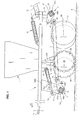
- the front of the drill symbolized by the reference AV in Figures 1 and 3, is located on the left of Figures 1 to 5.
- the seed drill shown in Figure 1 comprises a substantially horizontal frame 1 which supports a hopper 11 for containing the seed to be dispensed, and which is provided at the front of a drawbar 10 to a tractor (not shown).
- the drawbar arm extends for a substantially greater length than that shown in FIGS. 1 and 3, the arm having been interrupted in these figures so as not to leave the frame reserved for the drawing.
- the frame 1 and the drawbar 10 form a rigid and indeformable assembly, for example made of welded metal sections.
- Each of the arms 2 is equipped, in known manner, firstly, with a pair of sowing discs 5a, 5b each provided with a coulter (or rasette) adapted to be supplied with seed from said hopper 11 by means of a suitable flexible tubing 50a, 50b.
- sowing discs are located on each side of the support arm 2, with a certain longitudinal offset; in addition, they are slightly inclined with respect to a longitudinal vertical plane, in the direction of forward convergence; their axis of rotation, horizontal, forms an angle ⁇ of the order of 93 ° relative to a transverse axis (see Figure 5).
- a pair of follower rollers 6a, 6b also supported by the arm 2, on each side thereof, and guided in rotation, adapted to roll on the ground and compact it.
- the mounting of these disks is in accordance with the recommendations of the EP 0 611 204 , with a "tandem" mounting, double crank; such a provision, however, is not required.
- each of the arms 2 is secured to the frame 1 by means of a pair of elastic articulation systems 3 and 4 arranged, respectively, at its front and rear ends, and each of them torsion works, so as to develop a torque that urges the arm 2 down to firmly apply the sowing tools 5a, 5b and follower rollers 6a. 6b against the ground S.
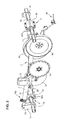
- the two torsion hinge systems are similar, each comprising two square section tubes mounted coaxially within each other, with an angular offset of 45 ° and a slight clearance allowing rotation of the inner tube relative to the outer tube, and four prestressed rolls 300, flexible and elastic material, such as rubber, for example cylindrical, disposed at the periphery of the inner tube and ensuring the torque between these two tubes.
- the front articulation 3 comprises a central tube (or bar) 72 of square section which extends horizontally over the entire width of the drill.
- this tube 72 is surrounded coaxially by a tubular sleeve 30, also of square section.
- this sheath is in fact constituted by two half-shells in "V" contiguous and bolted. Its square shape is offset by an angle of 45 ° to that of the inner tube, leaving room for each coil 300, which is mounted with a certain tightening, that is to say, pre-compressed between the two tubes .
- Each of the tubular sleeves 30 is integral with a pivoting rod 31.
- the latter extends forwardly the carrier arm that it equips, and is articulated on the front end of this arm by a transverse axis and horizontal axis 20.
- the inner tube 72 is integral in rotation with a spreader 71 consisting of a pair of parallel flanges having a square opening through which the tube 72 (see Figure 2); this rudder 71 is articulated by an axis 70 at the end of the rod of at least one double-acting hydraulic cylinder 7, whose body is itself articulated to a piece 16 in the form of a yoke, integral with the frame 1.
- a spreader 71 consisting of a pair of parallel flanges having a square opening through which the tube 72 (see Figure 2); this rudder 71 is articulated by an axis 70 at the end of the rod of at least one double-acting hydraulic cylinder 7, whose body is itself articulated to a piece 16 in the form of a yoke, integral with the frame 1.
- a single control cylinder 7 which acts in the center of the tube 72.
- This cylinder has adjustable stop blocks 700 able to limit the retraction stroke of the cylinder.
- the rear articulation system 4 has a configuration similar to that just described. It comprises an internal tube (or bar) 15 of square section through square sleeves 40 integral with each arm, with the interposition of flexible and resilient strands 400.
- the central tube 15 is immobilized in rotation; it passes through complementary square openings formed in mounting plates 14 fixed under the frame 1, at the rear of it.
- the outer tube 40 is integral with a link 41, articulated to a second link 42, which is articulated by an axis 21 at the rear end of the corresponding arm 2.
- each arm has a certain freedom of vertical movement thanks to the presence of the elastic joints 3, 4, which allow the tools and the follower rollers to cross uneven ground and obstacles, such as pebbles, without damage.
- the frame 1 remains, meanwhile, substantially parallel to the ground S.
- This (s) cylinder (s) is (are) of course controlled (s) remotely by the operator, from the cab of the tractor.
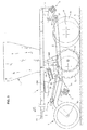
- the second embodiment of the drill illustrated in FIGS. 3 and 4 is similar to the preceding one, except that it is equipped with a series of front support wheels 8, mounted on each support arm 2, in a configuration similar to that which is the subject of the document EP 1,212,932 , which can be referred to as needed.
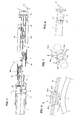
- the wheel 8 is mounted and guided in rotation at the end of an arcuate lever 9 which bypasses the elastic articulation 3 from above, and which is articulated at its rear end on the front end of the arm 2.
- an arcuate lever 9 which bypasses the elastic articulation 3 from above, and which is articulated at its rear end on the front end of the arm 2.
- it is the same axis 20 as that by which the link 31 is articulated on the arm 2, which also provides this function.
- This preferred arrangement is however not mandatory, the hinge pins can be distinct.
- the lever 9 could just as well bypass the joint 3 from below.
- a adjusting device 93 For this purpose the top of the lever is provided with a plate 91 having a through opening through which a longitudinal rod 92 passes. The latter is fixed and articulated by its rear end to the arm 2.
- the shims 930 may comprise two half-shells 93 1 connected by an elastically deformable reinforcement 932 which tends normally to bring them closer to one another so that they grip the rod 92 in the manner of a clamp.
- the two half shells deviate from each other (arrows k ), which allows to remove the hold; it can then be placed by simply snapping on the rod 92, on the other side of the wafer 91, the total number of shims remaining the same, regardless of the setting.
- the opening of the wafer 91 in which the rod 92 passes is preferably oblong (in the form of vertical light) to allow a functional clearance between the rod and the opening and the passage of the shims from one side to the other.
- This device for adjusting the height of the wheel 8 is only one possible embodiment, among others.
- the presence of the front wheel 8, adjustable in height, improves the distribution of the loads on the ground and the control of the working depth.
- the adjustment of the pressure, by means of the shims 700 equipping the jack 7, makes it possible to adjust the distribution of the load between the rear bearing zones (constituted by the rollers 6a and 6b), and before (constituted by wheel 8).
- the rear end of the arm 2 is connected to the hinge 4 not by means of a toggle, but by means of a rod 41, the hinge 21 being carried by an eccentric 43 rotatable relative to the support arm.
- the transverse tubes (or bars) 72 and 15 constituting the front and rear elastic joints are cut into three parts: a fixed central part and two articulated lateral parts, capable of being raised towards the top together with the sleeves 30, 40 which surrounds them, and the arms 2 with their tools, to enter the road gauge, according to an arrangement known per se.
- a control cylinder 7 is associated of course with each pipe section, and the various cylinders can be coupled so as to act concomitantly.
Landscapes
- Life Sciences & Earth Sciences (AREA)
- Soil Sciences (AREA)
- Environmental Sciences (AREA)
- Sowing (AREA)
- Spinning Or Twisting Of Yarns (AREA)
- Feeding And Guiding Record Carriers (AREA)
Applications Claiming Priority (1)
| Application Number | Priority Date | Filing Date | Title |
|---|---|---|---|
| FR0600756A FR2896659B1 (fr) | 2006-01-27 | 2006-01-27 | Semoir comportant une serie de bras, porteurs de disques semeurs et de rouleaux suiveurs, supportes sous le chassis par l'intermediaire d'articulations elastiques |
Publications (2)
| Publication Number | Publication Date |
|---|---|
| EP1815730A1 true EP1815730A1 (de) | 2007-08-08 |
| EP1815730B1 EP1815730B1 (de) | 2008-09-10 |
Family
ID=36825537
Family Applications (1)
| Application Number | Title | Priority Date | Filing Date |
|---|---|---|---|
| EP07100473A Active EP1815730B1 (de) | 2006-01-27 | 2007-01-12 | Sämaschine, die eine Reihe von Armen, Halterungen für Säscheiben und Nachläufer umfasst, die auf dem Rahmen mit Hilfe von elastischen Gelenken befestigt sind |
Country Status (4)
| Country | Link |
|---|---|
| EP (1) | EP1815730B1 (de) |
| AT (1) | ATE407547T1 (de) |
| DE (1) | DE602007000110D1 (de) |
| FR (1) | FR2896659B1 (de) |
Cited By (4)
| Publication number | Priority date | Publication date | Assignee | Title |
|---|---|---|---|---|
| EP2055167A1 (de) * | 2007-10-30 | 2009-05-06 | Amazonen-Werke H. Dreyer GmbH & Co. KG | Sämaschine |
| WO2014127753A1 (en) | 2013-02-22 | 2014-08-28 | Farmet A.S. | Agricultural machine for sowing or the application of fertilizer |
| EP3225092A1 (de) | 2016-03-30 | 2017-10-04 | Sulky Burel | Säelement für sämaschine mit verbesserter säscheibe, und entsprechende sämaschine |
| CN111587638A (zh) * | 2020-06-02 | 2020-08-28 | 哈尔滨市农业科学院 | 一种双侧精量取种的水稻穴直播机构 |
Families Citing this family (1)
| Publication number | Priority date | Publication date | Assignee | Title |
|---|---|---|---|---|
| FR2923675B1 (fr) | 2007-11-16 | 2012-10-26 | Sulky Burel | Semoir permettant la distribution simultanee de graines et d'elements granulaires, notamment d'engrais |
Citations (9)
| Publication number | Priority date | Publication date | Assignee | Title |
|---|---|---|---|---|
| GB1218785A (en) | 1968-07-20 | 1971-01-13 | Samuel Moore | Improved method and means for agricultural seeding |
| FR2166951A7 (de) | 1971-11-11 | 1973-08-17 | Rejna Spa | |
| GB2040656A (en) | 1979-01-05 | 1980-09-03 | Moore S | Agricultural seed drills |
| WO1985005246A1 (en) | 1984-05-21 | 1985-12-05 | Väderstadverken Ab | Apparatus in dispensing machines for agriculture |
| GB2222756A (en) | 1988-09-20 | 1990-03-21 | Samuel Moore | Limiting depth of agricultural seeding |
| EP0611204A1 (de) | 1993-02-11 | 1994-08-17 | Sulky-Burel S.A. | Anordnung für die Scharen einer Sämaschine |
| EP1212932A1 (de) | 2000-12-05 | 2002-06-12 | Sulky-Burel S.A. | Sämaschine |
| EP1391147A1 (de) * | 2002-08-19 | 2004-02-25 | Josef Kerner | Säschiene mit mehreren gestaffelt angeordneten Säscharen mit nachgeordneten Druckrollen |
| FR2855714A1 (fr) | 2003-06-05 | 2004-12-10 | Auf Der Landwehr Gmbh | Semoir en ligne |
-
2006
- 2006-01-27 FR FR0600756A patent/FR2896659B1/fr not_active Expired - Fee Related
-
2007
- 2007-01-12 EP EP07100473A patent/EP1815730B1/de active Active
- 2007-01-12 DE DE602007000110T patent/DE602007000110D1/de active Active
- 2007-01-12 AT AT07100473T patent/ATE407547T1/de not_active IP Right Cessation
Patent Citations (9)
| Publication number | Priority date | Publication date | Assignee | Title |
|---|---|---|---|---|
| GB1218785A (en) | 1968-07-20 | 1971-01-13 | Samuel Moore | Improved method and means for agricultural seeding |
| FR2166951A7 (de) | 1971-11-11 | 1973-08-17 | Rejna Spa | |
| GB2040656A (en) | 1979-01-05 | 1980-09-03 | Moore S | Agricultural seed drills |
| WO1985005246A1 (en) | 1984-05-21 | 1985-12-05 | Väderstadverken Ab | Apparatus in dispensing machines for agriculture |
| GB2222756A (en) | 1988-09-20 | 1990-03-21 | Samuel Moore | Limiting depth of agricultural seeding |
| EP0611204A1 (de) | 1993-02-11 | 1994-08-17 | Sulky-Burel S.A. | Anordnung für die Scharen einer Sämaschine |
| EP1212932A1 (de) | 2000-12-05 | 2002-06-12 | Sulky-Burel S.A. | Sämaschine |
| EP1391147A1 (de) * | 2002-08-19 | 2004-02-25 | Josef Kerner | Säschiene mit mehreren gestaffelt angeordneten Säscharen mit nachgeordneten Druckrollen |
| FR2855714A1 (fr) | 2003-06-05 | 2004-12-10 | Auf Der Landwehr Gmbh | Semoir en ligne |
Cited By (5)
| Publication number | Priority date | Publication date | Assignee | Title |
|---|---|---|---|---|
| EP2055167A1 (de) * | 2007-10-30 | 2009-05-06 | Amazonen-Werke H. Dreyer GmbH & Co. KG | Sämaschine |
| WO2014127753A1 (en) | 2013-02-22 | 2014-08-28 | Farmet A.S. | Agricultural machine for sowing or the application of fertilizer |
| EP3225092A1 (de) | 2016-03-30 | 2017-10-04 | Sulky Burel | Säelement für sämaschine mit verbesserter säscheibe, und entsprechende sämaschine |
| CN111587638A (zh) * | 2020-06-02 | 2020-08-28 | 哈尔滨市农业科学院 | 一种双侧精量取种的水稻穴直播机构 |
| CN111587638B (zh) * | 2020-06-02 | 2024-05-28 | 哈尔滨市农业科学院 | 一种双侧精量取种的水稻穴直播机构 |
Also Published As
| Publication number | Publication date |
|---|---|
| DE602007000110D1 (de) | 2008-10-23 |
| EP1815730B1 (de) | 2008-09-10 |
| ATE407547T1 (de) | 2008-09-15 |
| FR2896659B1 (fr) | 2008-03-28 |
| FR2896659A1 (fr) | 2007-08-03 |
Similar Documents
| Publication | Publication Date | Title |
|---|---|---|
| EP1815730B1 (de) | Sämaschine, die eine Reihe von Armen, Halterungen für Säscheiben und Nachläufer umfasst, die auf dem Rahmen mit Hilfe von elastischen Gelenken befestigt sind | |
| FR2939601A1 (fr) | Element semeur pour machine agricole et semoir correspondant | |
| EP3549420B1 (de) | Einlegersystem für landwirtschaftliches material und landwirtschaftliche maschine mit diesem system | |
| FR2967546A1 (fr) | Semoir avec des elements d'appui decales | |
| EP2534933A1 (de) | Sämaschine mit Verdichtungselementen, die die Transporträder bilden | |
| EP3761774B1 (de) | Säelement mit einstellbarem presselement und zugehörige sämaschine | |
| EP1212932B1 (de) | Sämaschine | |
| EP2361491B1 (de) | Sämaschine mit Einstellvorrichtungen mit verringertem Raumbedarf | |
| EP3419406B1 (de) | Arbeitselement einer landwirtschaftlichen maschine mit einem system zur anpassung des anpressdrucks | |
| EP2168415B1 (de) | Verbesserte Furchenabdeckeinrichtung | |
| EP1195084B1 (de) | Verbesserts Sämaschine | |
| EP1787503B1 (de) | Bestellkombination | |
| EP1529432B1 (de) | Sämaschine mit einer Einstellvorrichtung | |
| EP2823701B1 (de) | Säelement mit Griff zum Einstellen des Sädrucks | |
| FR2835691A1 (fr) | Semoir | |
| EP0611204B1 (de) | Anordnung für die Scharen einer Sämaschine | |
| EP0966875B1 (de) | Sähmaschine | |
| FR2780238A1 (fr) | Semoir comportant des organes de reference, un dispositif d'ancrage automatique et des dispositifs d'appui escamotables limitant le deplacement de structures porteuses | |
| EP2638792B1 (de) | Drillmaschine mit einer verbesserten Tiefenverstellung | |
| EP1232680B1 (de) | Landwirtschaftliche Gerätenivellierungsbalken | |
| FR2556920A1 (fr) | Machine pour repandre une matiere sur une surface | |
| EP0847683A1 (de) | Grossflächen-Drillmaschine | |
| FR2606246A1 (fr) | Bineuse equipee d'une tremie a engrais | |
| EP4094554A1 (de) | Baugruppe mit landwirtschaftlichem bodenbearbeitungsgerät und zusätzlichem landwirtschaftlichen gerät | |
| FR3092225A1 (fr) | Elément semeur avec un dispositif de réglage automatique du terrage et semoir correspondant |
Legal Events
| Date | Code | Title | Description |
|---|---|---|---|
| PUAI | Public reference made under article 153(3) epc to a published international application that has entered the european phase |
Free format text: ORIGINAL CODE: 0009012 |
|
| AK | Designated contracting states |
Kind code of ref document: A1 Designated state(s): AT BE BG CH CY CZ DE DK EE ES FI FR GB GR HU IE IS IT LI LT LU LV MC NL PL PT RO SE SI SK TR |
|
| AX | Request for extension of the european patent |
Extension state: AL BA HR MK YU |
|
| 17P | Request for examination filed |
Effective date: 20071030 |
|
| AKX | Designation fees paid |
Designated state(s): AT BE BG CH CY CZ DE DK EE ES FI FR GB GR HU IE IS IT LI LT LU LV MC NL PL PT RO SE SI SK TR |
|
| GRAP | Despatch of communication of intention to grant a patent |
Free format text: ORIGINAL CODE: EPIDOSNIGR1 |
|
| GRAS | Grant fee paid |
Free format text: ORIGINAL CODE: EPIDOSNIGR3 |
|
| GRAA | (expected) grant |
Free format text: ORIGINAL CODE: 0009210 |
|
| AK | Designated contracting states |
Kind code of ref document: B1 Designated state(s): AT BE BG CH CY CZ DE DK EE ES FI FR GB GR HU IE IS IT LI LT LU LV MC NL PL PT RO SE SI SK TR |
|
| REG | Reference to a national code |
Ref country code: GB Ref legal event code: FG4D Free format text: NOT ENGLISH |
|
| REG | Reference to a national code |
Ref country code: CH Ref legal event code: EP |
|
| REG | Reference to a national code |
Ref country code: IE Ref legal event code: FG4D Free format text: LANGUAGE OF EP DOCUMENT: FRENCH |
|
| REF | Corresponds to: |
Ref document number: 602007000110 Country of ref document: DE Date of ref document: 20081023 Kind code of ref document: P |
|
| PG25 | Lapsed in a contracting state [announced via postgrant information from national office to epo] |
Ref country code: LT Free format text: LAPSE BECAUSE OF FAILURE TO SUBMIT A TRANSLATION OF THE DESCRIPTION OR TO PAY THE FEE WITHIN THE PRESCRIBED TIME-LIMIT Effective date: 20080910 |
|
| PG25 | Lapsed in a contracting state [announced via postgrant information from national office to epo] |
Ref country code: SI Free format text: LAPSE BECAUSE OF FAILURE TO SUBMIT A TRANSLATION OF THE DESCRIPTION OR TO PAY THE FEE WITHIN THE PRESCRIBED TIME-LIMIT Effective date: 20080910 Ref country code: LV Free format text: LAPSE BECAUSE OF FAILURE TO SUBMIT A TRANSLATION OF THE DESCRIPTION OR TO PAY THE FEE WITHIN THE PRESCRIBED TIME-LIMIT Effective date: 20080910 Ref country code: FI Free format text: LAPSE BECAUSE OF FAILURE TO SUBMIT A TRANSLATION OF THE DESCRIPTION OR TO PAY THE FEE WITHIN THE PRESCRIBED TIME-LIMIT Effective date: 20080910 Ref country code: AT Free format text: LAPSE BECAUSE OF FAILURE TO SUBMIT A TRANSLATION OF THE DESCRIPTION OR TO PAY THE FEE WITHIN THE PRESCRIBED TIME-LIMIT Effective date: 20080910 |
|
| NLV1 | Nl: lapsed or annulled due to failure to fulfill the requirements of art. 29p and 29m of the patents act | ||
| PG25 | Lapsed in a contracting state [announced via postgrant information from national office to epo] |
Ref country code: ES Free format text: LAPSE BECAUSE OF FAILURE TO SUBMIT A TRANSLATION OF THE DESCRIPTION OR TO PAY THE FEE WITHIN THE PRESCRIBED TIME-LIMIT Effective date: 20081221 Ref country code: BG Free format text: LAPSE BECAUSE OF FAILURE TO SUBMIT A TRANSLATION OF THE DESCRIPTION OR TO PAY THE FEE WITHIN THE PRESCRIBED TIME-LIMIT Effective date: 20081210 |
|
| PG25 | Lapsed in a contracting state [announced via postgrant information from national office to epo] |
Ref country code: SK Free format text: LAPSE BECAUSE OF FAILURE TO SUBMIT A TRANSLATION OF THE DESCRIPTION OR TO PAY THE FEE WITHIN THE PRESCRIBED TIME-LIMIT Effective date: 20080910 Ref country code: RO Free format text: LAPSE BECAUSE OF FAILURE TO SUBMIT A TRANSLATION OF THE DESCRIPTION OR TO PAY THE FEE WITHIN THE PRESCRIBED TIME-LIMIT Effective date: 20080910 Ref country code: PT Free format text: LAPSE BECAUSE OF FAILURE TO SUBMIT A TRANSLATION OF THE DESCRIPTION OR TO PAY THE FEE WITHIN THE PRESCRIBED TIME-LIMIT Effective date: 20090210 Ref country code: NL Free format text: LAPSE BECAUSE OF FAILURE TO SUBMIT A TRANSLATION OF THE DESCRIPTION OR TO PAY THE FEE WITHIN THE PRESCRIBED TIME-LIMIT Effective date: 20080910 Ref country code: IS Free format text: LAPSE BECAUSE OF FAILURE TO SUBMIT A TRANSLATION OF THE DESCRIPTION OR TO PAY THE FEE WITHIN THE PRESCRIBED TIME-LIMIT Effective date: 20090110 |
|
| PLBE | No opposition filed within time limit |
Free format text: ORIGINAL CODE: 0009261 |
|
| STAA | Information on the status of an ep patent application or granted ep patent |
Free format text: STATUS: NO OPPOSITION FILED WITHIN TIME LIMIT |
|
| PG25 | Lapsed in a contracting state [announced via postgrant information from national office to epo] |
Ref country code: EE Free format text: LAPSE BECAUSE OF FAILURE TO SUBMIT A TRANSLATION OF THE DESCRIPTION OR TO PAY THE FEE WITHIN THE PRESCRIBED TIME-LIMIT Effective date: 20080910 Ref country code: DK Free format text: LAPSE BECAUSE OF FAILURE TO SUBMIT A TRANSLATION OF THE DESCRIPTION OR TO PAY THE FEE WITHIN THE PRESCRIBED TIME-LIMIT Effective date: 20080910 |
|
| 26N | No opposition filed |
Effective date: 20090611 |
|
| PG25 | Lapsed in a contracting state [announced via postgrant information from national office to epo] |
Ref country code: MC Free format text: LAPSE BECAUSE OF NON-PAYMENT OF DUE FEES Effective date: 20090131 Ref country code: IT Free format text: LAPSE BECAUSE OF FAILURE TO SUBMIT A TRANSLATION OF THE DESCRIPTION OR TO PAY THE FEE WITHIN THE PRESCRIBED TIME-LIMIT Effective date: 20080910 |
|
| PG25 | Lapsed in a contracting state [announced via postgrant information from national office to epo] |
Ref country code: SE Free format text: LAPSE BECAUSE OF FAILURE TO SUBMIT A TRANSLATION OF THE DESCRIPTION OR TO PAY THE FEE WITHIN THE PRESCRIBED TIME-LIMIT Effective date: 20081210 |
|
| PG25 | Lapsed in a contracting state [announced via postgrant information from national office to epo] |
Ref country code: BE Free format text: LAPSE BECAUSE OF NON-PAYMENT OF DUE FEES Effective date: 20090131 |
|
| PG25 | Lapsed in a contracting state [announced via postgrant information from national office to epo] |
Ref country code: PL Free format text: LAPSE BECAUSE OF FAILURE TO SUBMIT A TRANSLATION OF THE DESCRIPTION OR TO PAY THE FEE WITHIN THE PRESCRIBED TIME-LIMIT Effective date: 20080910 |
|
| PG25 | Lapsed in a contracting state [announced via postgrant information from national office to epo] |
Ref country code: GR Free format text: LAPSE BECAUSE OF FAILURE TO SUBMIT A TRANSLATION OF THE DESCRIPTION OR TO PAY THE FEE WITHIN THE PRESCRIBED TIME-LIMIT Effective date: 20081211 |
|
| PG25 | Lapsed in a contracting state [announced via postgrant information from national office to epo] |
Ref country code: LU Free format text: LAPSE BECAUSE OF NON-PAYMENT OF DUE FEES Effective date: 20090112 |
|
| PG25 | Lapsed in a contracting state [announced via postgrant information from national office to epo] |
Ref country code: HU Free format text: LAPSE BECAUSE OF FAILURE TO SUBMIT A TRANSLATION OF THE DESCRIPTION OR TO PAY THE FEE WITHIN THE PRESCRIBED TIME-LIMIT Effective date: 20090311 |
|
| PG25 | Lapsed in a contracting state [announced via postgrant information from national office to epo] |
Ref country code: TR Free format text: LAPSE BECAUSE OF FAILURE TO SUBMIT A TRANSLATION OF THE DESCRIPTION OR TO PAY THE FEE WITHIN THE PRESCRIBED TIME-LIMIT Effective date: 20080910 |
|
| REG | Reference to a national code |
Ref country code: CH Ref legal event code: PL |
|
| PG25 | Lapsed in a contracting state [announced via postgrant information from national office to epo] |
Ref country code: CY Free format text: LAPSE BECAUSE OF FAILURE TO SUBMIT A TRANSLATION OF THE DESCRIPTION OR TO PAY THE FEE WITHIN THE PRESCRIBED TIME-LIMIT Effective date: 20080910 |
|
| PG25 | Lapsed in a contracting state [announced via postgrant information from national office to epo] |
Ref country code: CH Free format text: LAPSE BECAUSE OF NON-PAYMENT OF DUE FEES Effective date: 20110131 Ref country code: LI Free format text: LAPSE BECAUSE OF NON-PAYMENT OF DUE FEES Effective date: 20110131 |
|
| REG | Reference to a national code |
Ref country code: FR Ref legal event code: PLFP Year of fee payment: 10 |
|
| PGFP | Annual fee paid to national office [announced via postgrant information from national office to epo] |
Ref country code: IE Payment date: 20151218 Year of fee payment: 10 |
|
| PGFP | Annual fee paid to national office [announced via postgrant information from national office to epo] |
Ref country code: CZ Payment date: 20151218 Year of fee payment: 10 |
|
| REG | Reference to a national code |
Ref country code: FR Ref legal event code: PLFP Year of fee payment: 11 |
|
| PG25 | Lapsed in a contracting state [announced via postgrant information from national office to epo] |
Ref country code: CZ Free format text: LAPSE BECAUSE OF NON-PAYMENT OF DUE FEES Effective date: 20170112 |
|
| REG | Reference to a national code |
Ref country code: IE Ref legal event code: MM4A |
|
| REG | Reference to a national code |
Ref country code: FR Ref legal event code: PLFP Year of fee payment: 12 |
|
| PG25 | Lapsed in a contracting state [announced via postgrant information from national office to epo] |
Ref country code: IE Free format text: LAPSE BECAUSE OF NON-PAYMENT OF DUE FEES Effective date: 20170112 |
|
| PGFP | Annual fee paid to national office [announced via postgrant information from national office to epo] |
Ref country code: GB Payment date: 20190220 Year of fee payment: 13 |
|
| PGFP | Annual fee paid to national office [announced via postgrant information from national office to epo] |
Ref country code: DE Payment date: 20200211 Year of fee payment: 14 |
|
| GBPC | Gb: european patent ceased through non-payment of renewal fee |
Effective date: 20200112 |
|
| PG25 | Lapsed in a contracting state [announced via postgrant information from national office to epo] |
Ref country code: GB Free format text: LAPSE BECAUSE OF NON-PAYMENT OF DUE FEES Effective date: 20200112 |
|
| REG | Reference to a national code |
Ref country code: DE Ref legal event code: R119 Ref document number: 602007000110 Country of ref document: DE |
|
| PG25 | Lapsed in a contracting state [announced via postgrant information from national office to epo] |
Ref country code: DE Free format text: LAPSE BECAUSE OF NON-PAYMENT OF DUE FEES Effective date: 20210803 |
|
| PGFP | Annual fee paid to national office [announced via postgrant information from national office to epo] |
Ref country code: FR Payment date: 20231215 Year of fee payment: 18 |