EP1815565B1 - Verfahren und vorrichtung zum modifizieren von ausserband-reflexion für ein laserelement - Google Patents
Verfahren und vorrichtung zum modifizieren von ausserband-reflexion für ein laserelement Download PDFInfo
- Publication number
- EP1815565B1 EP1815565B1 EP05810607.1A EP05810607A EP1815565B1 EP 1815565 B1 EP1815565 B1 EP 1815565B1 EP 05810607 A EP05810607 A EP 05810607A EP 1815565 B1 EP1815565 B1 EP 1815565B1
- Authority
- EP
- European Patent Office
- Prior art keywords
- phase
- change
- laser element
- bragg grating
- laser light
- Prior art date
- Legal status (The legal status is an assumption and is not a legal conclusion. Google has not performed a legal analysis and makes no representation as to the accuracy of the status listed.)
- Expired - Lifetime
Links
Images


Classifications
-
- H—ELECTRICITY
- H01—ELECTRIC ELEMENTS
- H01S—DEVICES USING THE PROCESS OF LIGHT AMPLIFICATION BY STIMULATED EMISSION OF RADIATION [LASER] TO AMPLIFY OR GENERATE LIGHT; DEVICES USING STIMULATED EMISSION OF ELECTROMAGNETIC RADIATION IN WAVE RANGES OTHER THAN OPTICAL
- H01S3/00—Lasers, i.e. devices using stimulated emission of electromagnetic radiation in the infrared, visible or ultraviolet wave range
- H01S3/05—Construction or shape of optical resonators; Accommodation of active medium therein; Shape of active medium
- H01S3/06—Construction or shape of active medium
- H01S3/063—Waveguide lasers, i.e. whereby the dimensions of the waveguide are of the order of the light wavelength
- H01S3/067—Fibre lasers
- H01S3/0675—Resonators including a grating structure, e.g. distributed Bragg reflectors [DBR] or distributed feedback [DFB] fibre lasers
-
- H—ELECTRICITY
- H01—ELECTRIC ELEMENTS
- H01S—DEVICES USING THE PROCESS OF LIGHT AMPLIFICATION BY STIMULATED EMISSION OF RADIATION [LASER] TO AMPLIFY OR GENERATE LIGHT; DEVICES USING STIMULATED EMISSION OF ELECTROMAGNETIC RADIATION IN WAVE RANGES OTHER THAN OPTICAL
- H01S3/00—Lasers, i.e. devices using stimulated emission of electromagnetic radiation in the infrared, visible or ultraviolet wave range
- H01S3/05—Construction or shape of optical resonators; Accommodation of active medium therein; Shape of active medium
- H01S3/06—Construction or shape of active medium
- H01S3/063—Waveguide lasers, i.e. whereby the dimensions of the waveguide are of the order of the light wavelength
- H01S3/067—Fibre lasers
- H01S3/06708—Constructional details of the fibre, e.g. compositions, cross-section, shape or tapering
-
- H—ELECTRICITY
- H01—ELECTRIC ELEMENTS
- H01S—DEVICES USING THE PROCESS OF LIGHT AMPLIFICATION BY STIMULATED EMISSION OF RADIATION [LASER] TO AMPLIFY OR GENERATE LIGHT; DEVICES USING STIMULATED EMISSION OF ELECTROMAGNETIC RADIATION IN WAVE RANGES OTHER THAN OPTICAL
- H01S3/00—Lasers, i.e. devices using stimulated emission of electromagnetic radiation in the infrared, visible or ultraviolet wave range
- H01S3/05—Construction or shape of optical resonators; Accommodation of active medium therein; Shape of active medium
- H01S3/08—Construction or shape of optical resonators or components thereof
- H01S3/08018—Mode suppression
- H01S3/08022—Longitudinal modes
- H01S3/08031—Single-mode emission
Definitions
- the present invention relates to lasers.
- the present invention relates to a distributed feedback (DFB) fibre laser having improved characteristics for use in fibre laser arrays.
- DFB distributed feedback
- DFB lasers are a variety of lasers which include one or more Bragg gratings which act as reflection elements within a laser active region. This technique of co-locating the gain medium and the feedback grating is applicable to fibre lasers such as those which employ a gain medium that has been doped with erbium.
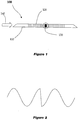
- Fibre laser 100 includes a doped fibre 110 and Bragg grating 120 incorporating a phase discontinuity located in the middle section 130 of grating 120.
- the Bragg grating is provided by a UV induced periodic spatial variation of the refractive index of the gain medium.
- Other techniques which provide a Bragg grating structure include periodic modulation of the gain or loss of the active region or potentially the cutting of a periodic pattern of grooves into the cladding of the fibre might also conceivably be used.
- Fibre laser 100 is activated by optical pumping 140 which involves pumping light having a wavelength that matches with the appropriate absorption band of the active material or gain medium through a passive fibre connected to fibre laser 100.
- optical pumping 140 involves pumping light having a wavelength that matches with the appropriate absorption band of the active material or gain medium through a passive fibre connected to fibre laser 100.
- a ⁇ phase shift is introduced into the middle section 130 of grating 120.
- the introduction of this phase shift ensures a lowest threshold, highly confined fundamental laser mode operating at essentially the Bragg wavelength ⁇ B .
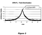
- the typical field distribution of such a laser is shown in Figure 3 where it can be seen that the field has a maximum at the location of the phase shift and decays exponentially away from the centre of grating 120.
- the spatial width of the field distribution depends on
- One of the major applications of a DFB fibre laser is to incorporate a number of fibre lasers into one continuous fibre to form a fibre laser array.
- Each of the fibre lasers are tuned to operate at slightly different wavelengths ⁇ B 1 , ⁇ B 2 etc with the advantage that optical pumping at a single wavelength may be employed to cause each of the DFB fibre laser sections to lase.
- This provides a means for wave division multiplexing as laser emissions from each fibre laser section travel down the common fibre and may be sampled using interferometric processing downstream.
- Arrays of DFB fibre lasers of this type have been employed in a number of applications including sensor arrays where the wavelength output of each fibre laser varies according to the local value of a physical characteristic of the environment such as the temperature or level of sound, to uses such as multi-wavelength laser sources.
- the ability of each fibre laser section to emit light essentially at the respective Bragg wavelength is critical as each of the wavelengths ⁇ B 1 , ⁇ B 2 etc. will be tightly spaced due to the finite emission band-width available to the gain medium, which must be similar for each laser due to the requirement that each fibre laser is activated by pump light having the same wavelength.
- DFB fibre lasers have a number of disadvantages which directly affect the performance of fibre laser arrays based on a number of fibre laser sections.
- the Bragg grating is designed to reflect light in only a narrow band about the Bragg wavelength ⁇ B and to be essentially transparent outside the band there is in practice out of band reflection associated with the side-lobes of the Bragg grating.
- ⁇ ⁇ ⁇ B 2 ⁇
- the laser wavelength will be sensitive to both small changes in distance d between the fibre laser sections and the reflection coefficient r ( v ) from the adjacent lasers.
- this is undesirable in the example of a sensor array as the intent is to measure changes to the laser wavelength caused by local changes to the Bragg wavelength of the grating of the respective fibre laser section.
- the physical length L of the grating structure can be increased.
- this has the obvious disadvantage of lengthening the fibre laser array where compactness is often a major requirement.
- lengthening of each fibre laser section implies that a sample is taken from a distributed region as opposed to the fibre laser section acting as a point sensor.
- a sensor design will also require multiple point sensors in close proximity and lengthening the grating structure for each fibre laser section can greatly add to the mechanical constraints in dealing with such a sensor array.
- a DFB laser diode having a distributed phase shift of larger than ⁇ for single-mode emission at for example minimum threshold is known from H.
- a DFB fiber laser having a distributed phase shift of ⁇ is known from WO 95/31020 A1 . It is an object of the invention to provide a DFB laser having improved characteristics that enable the incorporation of these devices into multiple DFB laser arrangements.
- the present invention accordingly provides a laser element for producing laser light including:
- the laser element may be customised for incorporation into a system incorporating an array of multiple laser elements. Said change in phase is adjusted to reduce out of band reflection of said laser element. Said change in phase is adjusted to continuously change over an extended region of said laser element. A maximum phase change ⁇ of said change in phase is greater than ⁇ .
- said maximum phase change ⁇ of said change in phase is determined in part by a length of said extended region.
- said maximum phase change ⁇ increases as said length of said extended region increases.
- ⁇ ( z ) is a coupling coefficient of said Bragg grating structure
- z 2 and z 3 define the boundaries of said phase transition region.
- Said laser element is a distributed feedback (DFB) fibre laser (FL)
- DFB distributed feedback
- a DFB FL distributed feedback fibre laser
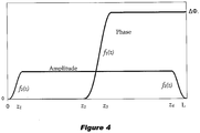
- DFB FL is assumed to be of length L and is divided into five regions corresponding to first region ranging from 0 ⁇ z ⁇ z 1 , second region z 1 ⁇ z ⁇ z 2 , third region z 2 ⁇ z ⁇ z 3 , fourth region z 3 ⁇ z ⁇ z 4 and fifth region z 4 ⁇ z ⁇ L where z measures longitudinal extent along the fibre.
- Apodisation is applied to both the amplitude and phase of the grating coupling coefficient ⁇ ( z ).
- Phase apodisation is applied to the third region which would typically be a step function in a prior art DFB FL such as that illustrated in Figure 1 .
- other suitably defined smooth transition functions which vary from 0 to 1 and whose derivatives vanish at the relevant boundaries may be employed.
- the value for the constant ⁇ is determined by solving numerically the following coupled equations thereby determining the value of ⁇ that ensures optimal single mode performance at the Bragg frequency.
- Equation 19 For the derivation of these equations see in particular Equation 19 as described in the article entitled “ Experimental and Theoretical Characterisation of the Mode Profile of Single-Mode DFB Fiber Lasers” (IEEE Journal of Quantum Electronics, Vol. 41, No. 6, June 2005 ). These coupled equations are then solved iteratively for ⁇ for reasonable choices of f 1 ( z ) such as that described above.
- phase shift step value or maximum phase change ⁇ will always be greater than ⁇ .
- the optimal condition for single mode performance whereby the optimum amount of energy is confined in one mode has always incorporated a phase shift step value or maximum phase change of ⁇ .
- of grating coupling coefficient may also be modified.
- is modified according to the relationship
- f 2 ( z ) ⁇
- f 2 ( z ) is defined in a similar manner to f 1 ( z ).
- amplitude apodisation of this nature is known in the prior art it does not in of itself successfully address issues with out of band reflection as highlighted previously. However, it may be employed in addition to phase apodisation according to the present invention to further reduce the effects of side lobes thereby resulting in minimised out of band reflection in a fibre laser section.
- a calculated curve for the field distribution of a DFB FL which has been apodised according to the present invention is compared with the field distribution of a corresponding standard DFB FL.
- the region z 3 - z 2 corresponds to 0.2 L .
- the phase shift region has now extended in size to occupy approximately 20% of the device length, the associated increase in the laser mode width and hence overall device length is only 4% and as such only represents a very small increase.
- plot A depicts the spectral reflection curve for a non-apodised laser of the prior art.
- this invention makes it possible to achieve very low out of band reflectivity without having to substantially increase the total device length thereby making DFB FLs adopting this invention most suitable for incorporation in linear multiplexed fibre laser arrays.
- the invention partly resides in realising that scattering from the normal discrete ⁇ phase shift employed in standard DFB FL contributes substantially to the spectral reflection curve.
- adjusting and modifying the shape and/or associated magnitude of this phase shift is important when attempting to substantially reduce the out of band spectral reflection.
Landscapes
- Physics & Mathematics (AREA)
- Electromagnetism (AREA)
- Engineering & Computer Science (AREA)
- Plasma & Fusion (AREA)
- Optics & Photonics (AREA)
- Semiconductor Lasers (AREA)
- Lasers (AREA)
Claims (14)
- Faserlaserelement mit verteilter Rückkopplung zum Erzeugen von Laserlicht mit:einem aktiven Medium, welches durch optische Pumpmittel angeregt ist, um stimulierte Emission von Licht zu erzeugen, undeiner Bragggitterstruktur zum Bereitstellen von optischem Feedback für das aktive Medium bei der Braggwellenlänge λB, wobei die Bragggitterstruktur einen komplexen Kopplungskoeffizienten κ(z) aufweist, gekennzeichnet durch die Beziehung κ(z) = πΔn(z)e -iϕ(z)/λ, worin z ein Maß der longitudinalen Strecke entlang des Faserlaserelements mit verteilter Rückkopplung, welches eine Gesamtvorrichtungslänge L aufweist, ist, Δn(z) eine Brechungsindexmodulation der Bragggitterstruktur ist, und ϕ(z) eine Änderung der Phase des Gitters in einem Phasenübergangsbereich der Bragggitterstruktur ist, wobei die Änderung der Phase ϕ(z) des Gitters des Phasenübergangsbereichs angepasst ist, um sich über einen erweiterten Bereich des Faserlaserelements mit verteilter Rückkopplung mit einer maximalen Phasenänderung ΔΦ, welche größer ist als π, kontinuierlich zu ändern, um eine Außerbandreflexion r(v) der Bragggitterstruktur des Faserlaserelements mit verteilter Rückkopplung gegenüber einer Bragggitterstruktur, welche eine lokalisierte π Phasenverschiebung aufweist, zu reduzieren, wobei die Außerbandreflexion r(v) der Bragggitterstruktur durch die Beziehung
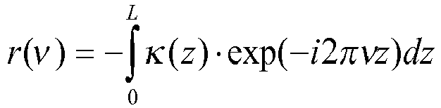 wobei v die Verstimmung von der Braggfrequenz, welche durch
- Laserelement zum Erzeugen von Laserlicht nach Anspruch 1, wobei die maximale Phasenänderung ΔΦ der Änderung der Phase teilweise durch eine Länge des erweiterten Bereichs bestimmt ist.
- Laserelement zum Erzeugen von Laserlicht nach Anspruch 2, wobei die maximale Phasenänderung ΔΦ zunimmt, während die Länge des erweiterten Bereichs zunimmt.
- Laserelement zum Erzeugen von Laserlicht nach einem der Ansprüche 1 bis 3, wobei ϕ(z) durch einen kontinuierlichen Phasenübergang φ(z) = f 1(z)ΔΦ gekennzeichnet ist, wobei f 1(z) eine Funktion mit den Randbedingungen f 1(z 2) = 0 und f 1(z 3) = 1 ist, wobei z 2 und z 3 die Grenzen des Phasenübergangsbereichs definieren.
- Laserelement zum Erzeugen von Laserlicht nach Anspruch 4, wobei f 1(z) durch

- Laserelement zum Erzeugen von Laserlicht nach Anspruch 4 oder 5, wobei die maximale Phasenänderung ΔΦ durch Lösen der gekoppelten Gleichungen für ΔΦ und Hilfsfunktion q(z)


- Laserelement zum Erzeugen von Laserlicht nach Anspruch 4 oder 5, wobei die maximale Phasenänderung ΔΦ der glatten Änderung der Phase durch

- Verfahren zum Erzeugen von Laserlicht von einem Faserlaserelement mit verteilter Rückkopplung, wobei das Verfahren die Schritte beinhaltet:optisches Pumpen eines aktiven Mediums, um eine stimulierte Emission von Licht zu erzeugen; undAnpassen einer Änderung einer Phase eines Phasenübergangsbereichs einer Bragggitterstruktur, wobei der Phasenübergangsbereich eine Änderung der Phase ϕ(z) des Gitters bereitstellt, wobei die Bragggitterstruktur optisches Feedback für das aktive Medium bei der Braggwellenlänge λB bereitstellt und einen komplexen Kopplungskoeffizienten κ(z) aufweist, gekennzeichnet durch die Beziehung κ(z) = πΔn(z)e -iϕ(z)/λ, worin z ein Maß der longitudinalen Strecke entlang des Faserlaserelements mit verteilter Rückkopplung, welches eine Gesamtvorrichtungslänge L aufweist, ist, Δn(z) eine Brechungsindexmodulation des Bragggitters ist, wobei das Anpassen der Änderung der Phase des Phasenübergangsbereichs das Anpassen der Änderung der Phase ϕ(z) des Gitters des Phasenübergangsbereichs beinhaltet, um die Änderung kontinuierlich über einen erweiterten Bereich des Faserlaserelement mit verteilter Rückkopplung mit einer maximalen Phasenänderung ΔΦ, welche größer ist als π, zu ändern, um eine Außerbandreflexion r(v) der Bragggitterstruktur des Faserlaserelements mit verteilter Rückkopplung gegenüber einer Bragggitterstruktur, welche eine lokalisierte π Phasenverschiebung aufweist, zu reduzieren, wobei die Außerbandreflexion r(v) der Bragggitterstruktur durch die Beziehung
 wobei v die Verstimmung von der Braggfrequenz, welche durch
- Verfahren zur Erzeugung von Laserlicht von einem Laserelement nach Anspruch 8, wobei die maximale Phasenänderung ΔΦ der Änderung der Phase teilweise durch eine Länge des erweiterten Bereichs bestimmt ist.
- Verfahren zur Erzeugung von Laserlicht von einem Laserelement nach Anspruch 9, wobei die maximale Phasenänderung ΔΦ zunimmt, während die Länge des erweiterten Bereichs zunimmt.
- Verfahren zur Erzeugung von Laserlicht von einem Laserelement nach einem der Ansprüche 8 bis 10, wobei ϕ(z) durch einen kontinuierlichen Phasenübergang φ(z) = f 1(z)ΔΦ gekennzeichnet ist, wobei f 1(z) eine Funktion mit den Randbedingungen f 1(z 2)=0 und f 1(z 3)=1 ist, wobei z 2 und z 3 die Grenzen des Phasenübergangsbereichs definieren.
- Verfahren zur Erzeugung von Laserlicht von einem Laserelement nach Anspruch 11, wobei f 1(z) durch

- Verfahren zur Erzeugung von Laserlicht von einem Laserelement nach Anspruch 11 oder 12, wobei das Verfahren ferner den Schritt des Bestimmens der maximalen Phasenänderung ΔΦ durch Lösen der gekoppelten Gleichungen für ΔΦ und Hilfsfunktion q(z)


- Verfahren zur Erzeugung von Laserlicht von einem Laserelement nach Anspruch 11 oder 12, wobei das Verfahren ferner den Schritt des Bestimmens der maximalen Phasenänderung ΔΦ der glatten Änderung der Phase durch Lösen von

Priority Applications (1)
| Application Number | Priority Date | Filing Date | Title |
|---|---|---|---|
| PL05810607T PL1815565T3 (pl) | 2004-11-26 | 2005-11-25 | Sposób i urządzenie do modyfikowania odbicia pasma dla elementów laserowych |
Applications Claiming Priority (2)
| Application Number | Priority Date | Filing Date | Title |
|---|---|---|---|
| AU2004906741A AU2004906741A0 (en) | 2004-11-26 | Laser element | |
| PCT/AU2005/001784 WO2006056016A1 (en) | 2004-11-26 | 2005-11-25 | Method and apparatus for modifying out of band reflection for a laser element |
Publications (3)
| Publication Number | Publication Date |
|---|---|
| EP1815565A1 EP1815565A1 (de) | 2007-08-08 |
| EP1815565A4 EP1815565A4 (de) | 2009-11-25 |
| EP1815565B1 true EP1815565B1 (de) | 2018-09-05 |
Family
ID=36497674
Family Applications (1)
| Application Number | Title | Priority Date | Filing Date |
|---|---|---|---|
| EP05810607.1A Expired - Lifetime EP1815565B1 (de) | 2004-11-26 | 2005-11-25 | Verfahren und vorrichtung zum modifizieren von ausserband-reflexion für ein laserelement |
Country Status (8)
| Country | Link |
|---|---|
| US (1) | US7848380B2 (de) |
| EP (1) | EP1815565B1 (de) |
| CA (1) | CA2589288C (de) |
| DK (1) | DK1815565T3 (de) |
| ES (1) | ES2701011T3 (de) |
| PL (1) | PL1815565T3 (de) |
| TR (1) | TR201818530T4 (de) |
| WO (1) | WO2006056016A1 (de) |
Family Cites Families (13)
| Publication number | Priority date | Publication date | Assignee | Title |
|---|---|---|---|---|
| FR2690572B1 (fr) | 1992-04-24 | 1994-07-22 | France Telecom | Structure laser a retroaction repartie. |
| GB9409033D0 (en) * | 1994-05-06 | 1994-06-29 | Univ Southampton | Optical fibre laser |
| US5710849A (en) * | 1995-11-01 | 1998-01-20 | Northern Telecom, Ltd. | Taper shapes for flatband response and sidelobe suppression in grating assisted optical coupler filters |
| US5668900A (en) * | 1995-11-01 | 1997-09-16 | Northern Telecom Limited | Taper shapes for sidelobe suppression and bandwidth minimization in distributed feedback optical reflection filters |
| JP3700245B2 (ja) | 1996-05-14 | 2005-09-28 | 株式会社日立製作所 | 位相シフト型分布帰還半導体レーザ |
| AU756444B2 (en) * | 1998-12-04 | 2003-01-16 | Weatherford Technology Holdings, Llc | Bragg grating pressure sensor |
| US6982996B1 (en) * | 1999-12-06 | 2006-01-03 | Weatherford/Lamb, Inc. | Large diameter optical waveguide, grating, and laser |
| EP1197738A1 (de) * | 2000-10-18 | 2002-04-17 | Abb Research Ltd. | Anisotroper Faserlaser-Sensor mit verteilter Rückkopplung |
| NO316148B1 (no) * | 2000-12-15 | 2003-12-15 | Optoplan As | Bolgeleder-laserkilde |
| US6654521B2 (en) * | 2002-01-23 | 2003-11-25 | Teraxion Inc. | Diffraction compensation of FBG phase masks for multi-channel sampling applications |
| US6638773B1 (en) | 2002-05-31 | 2003-10-28 | Applied Optoelectronics, Inc. | Method for fabricating single-mode DBR laser with improved yield |
| US6608855B1 (en) | 2002-05-31 | 2003-08-19 | Applied Optoelectronics, Inc. | Single-mode DBR laser with improved phase-shift section |
| US7627006B2 (en) * | 2003-09-18 | 2009-12-01 | Universite Laval | Multi-wavelength laser source |
-
2005
- 2005-11-25 TR TR2018/18530T patent/TR201818530T4/tr unknown
- 2005-11-25 ES ES05810607T patent/ES2701011T3/es not_active Expired - Lifetime
- 2005-11-25 CA CA2589288A patent/CA2589288C/en not_active Expired - Lifetime
- 2005-11-25 EP EP05810607.1A patent/EP1815565B1/de not_active Expired - Lifetime
- 2005-11-25 PL PL05810607T patent/PL1815565T3/pl unknown
- 2005-11-25 DK DK05810607.1T patent/DK1815565T3/da active
- 2005-11-25 WO PCT/AU2005/001784 patent/WO2006056016A1/en not_active Ceased
- 2005-11-25 US US11/791,645 patent/US7848380B2/en active Active
Non-Patent Citations (1)
| Title |
|---|
| None * |
Also Published As
| Publication number | Publication date |
|---|---|
| TR201818530T4 (tr) | 2019-01-21 |
| EP1815565A4 (de) | 2009-11-25 |
| US20080259985A1 (en) | 2008-10-23 |
| ES2701011T3 (es) | 2019-02-20 |
| US7848380B2 (en) | 2010-12-07 |
| EP1815565A1 (de) | 2007-08-08 |
| CA2589288A1 (en) | 2006-06-01 |
| DK1815565T3 (da) | 2019-01-02 |
| WO2006056016A1 (en) | 2006-06-01 |
| CA2589288C (en) | 2014-10-14 |
| PL1815565T3 (pl) | 2019-07-31 |
Similar Documents
| Publication | Publication Date | Title |
|---|---|---|
| EP0829740B1 (de) | Gitter zur Modenkopplung im optischem Wellenleiter | |
| EP0681681B1 (de) | Aktiver laseroptischer mehrpunkt-lasersensor | |
| KR102592497B1 (ko) | 모드 홉 프리 파장 튜닝을 위해 구성된 집적 광학 기반 외부 공동 레이저 | |
| US5703978A (en) | Temperature insensitive long-period fiber grating devices | |
| USH1813H (en) | Spectrally-selective fiber transmission filter system | |
| EP1340049B1 (de) | Einrichtung zur messung physikalischer grössen mit einem optischen sensor | |
| EP1753104B1 (de) | Halbleiterlaser | |
| US11215749B2 (en) | Optical fiber filter of wideband deleterious light and uses thereof | |
| EP0759216B1 (de) | Optischer faser-laser | |
| US8451453B2 (en) | Dynamic sensor of physical quantities with optical waveguide with optically pumped amplifier medium | |
| US8009947B2 (en) | Optical semiconductor device and method of controlling the same | |
| US11509116B2 (en) | Athermal angular output by combining a laser with a grating based antenna | |
| US20040197050A1 (en) | Optical distributed sensor with bragg grating sensing structure | |
| EP1804349A1 (de) | Halbleiterlaser mit Tastgitter mit DFB und DBR beinhaltend Phasensprünge | |
| US20040062483A1 (en) | Optical resonator and laser applications | |
| WO2001022542A2 (en) | Multi-wavelength laser system | |
| JP2011086714A (ja) | 波長可変レーザ | |
| US7848380B2 (en) | Method and apparatus for modifying out of band reflection for a laser element | |
| US20020136258A1 (en) | Semiconductor laser pump locker incorporating multiple gratings | |
| AU2005309330B2 (en) | Method and apparatus for modifying out of band reflection for a laser element | |
| Baghdasaryan et al. | Simulation of amplifying phase-shifted fiber Bragg gratings by the method of single expression | |
| Babin et al. | Fiber Lasers with Distributed Feedback | |
| Winz | The construction and computational modeling of a fiber Bragg grating tunable laser diode | |
| CA2388737A1 (en) | Ring laser |
Legal Events
| Date | Code | Title | Description |
|---|---|---|---|
| PUAI | Public reference made under article 153(3) epc to a published international application that has entered the european phase |
Free format text: ORIGINAL CODE: 0009012 |
|
| 17P | Request for examination filed |
Effective date: 20070524 |
|
| AK | Designated contracting states |
Kind code of ref document: A1 Designated state(s): AT BE BG CH CY CZ DE DK EE ES FI FR GB GR HU IE IS IT LI LT LU LV MC NL PL PT RO SE SI SK TR |
|
| DAX | Request for extension of the european patent (deleted) | ||
| A4 | Supplementary search report drawn up and despatched |
Effective date: 20091022 |
|
| RIC1 | Information provided on ipc code assigned before grant |
Ipc: H01S 3/08 20060101ALN20091016BHEP Ipc: H01S 3/067 20060101AFI20091016BHEP |
|
| 17Q | First examination report despatched |
Effective date: 20100326 |
|
| GRAP | Despatch of communication of intention to grant a patent |
Free format text: ORIGINAL CODE: EPIDOSNIGR1 |
|
| STAA | Information on the status of an ep patent application or granted ep patent |
Free format text: STATUS: GRANT OF PATENT IS INTENDED |
|
| INTG | Intention to grant announced |
Effective date: 20180316 |
|
| GRAS | Grant fee paid |
Free format text: ORIGINAL CODE: EPIDOSNIGR3 |
|
| GRAA | (expected) grant |
Free format text: ORIGINAL CODE: 0009210 |
|
| STAA | Information on the status of an ep patent application or granted ep patent |
Free format text: STATUS: THE PATENT HAS BEEN GRANTED |
|
| AK | Designated contracting states |
Kind code of ref document: B1 Designated state(s): AT BE BG CH CY CZ DE DK EE ES FI FR GB GR HU IE IS IT LI LT LU LV MC NL PL PT RO SE SI SK TR |
|
| REG | Reference to a national code |
Ref country code: GB Ref legal event code: FG4D |
|
| REG | Reference to a national code |
Ref country code: CH Ref legal event code: EP |
|
| REG | Reference to a national code |
Ref country code: AT Ref legal event code: REF Ref document number: 1038948 Country of ref document: AT Kind code of ref document: T Effective date: 20180915 |
|
| REG | Reference to a national code |
Ref country code: IE Ref legal event code: FG4D |
|
| REG | Reference to a national code |
Ref country code: DE Ref legal event code: R096 Ref document number: 602005054566 Country of ref document: DE |
|
| REG | Reference to a national code |
Ref country code: NL Ref legal event code: FP |
|
| REG | Reference to a national code |
Ref country code: DK Ref legal event code: T3 Effective date: 20181218 |
|
| REG | Reference to a national code |
Ref country code: SE Ref legal event code: TRGR |
|
| REG | Reference to a national code |
Ref country code: LT Ref legal event code: MG4D |
|
| PG25 | Lapsed in a contracting state [announced via postgrant information from national office to epo] |
Ref country code: LT Free format text: LAPSE BECAUSE OF FAILURE TO SUBMIT A TRANSLATION OF THE DESCRIPTION OR TO PAY THE FEE WITHIN THE PRESCRIBED TIME-LIMIT Effective date: 20180905 Ref country code: BG Free format text: LAPSE BECAUSE OF FAILURE TO SUBMIT A TRANSLATION OF THE DESCRIPTION OR TO PAY THE FEE WITHIN THE PRESCRIBED TIME-LIMIT Effective date: 20181205 Ref country code: GR Free format text: LAPSE BECAUSE OF FAILURE TO SUBMIT A TRANSLATION OF THE DESCRIPTION OR TO PAY THE FEE WITHIN THE PRESCRIBED TIME-LIMIT Effective date: 20181206 |
|
| REG | Reference to a national code |
Ref country code: AT Ref legal event code: MK05 Ref document number: 1038948 Country of ref document: AT Kind code of ref document: T Effective date: 20180905 |
|
| REG | Reference to a national code |
Ref country code: ES Ref legal event code: FG2A Ref document number: 2701011 Country of ref document: ES Kind code of ref document: T3 Effective date: 20190220 |
|
| PG25 | Lapsed in a contracting state [announced via postgrant information from national office to epo] |
Ref country code: LV Free format text: LAPSE BECAUSE OF FAILURE TO SUBMIT A TRANSLATION OF THE DESCRIPTION OR TO PAY THE FEE WITHIN THE PRESCRIBED TIME-LIMIT Effective date: 20180905 |
|
| PG25 | Lapsed in a contracting state [announced via postgrant information from national office to epo] |
Ref country code: IS Free format text: LAPSE BECAUSE OF FAILURE TO SUBMIT A TRANSLATION OF THE DESCRIPTION OR TO PAY THE FEE WITHIN THE PRESCRIBED TIME-LIMIT Effective date: 20190105 Ref country code: AT Free format text: LAPSE BECAUSE OF FAILURE TO SUBMIT A TRANSLATION OF THE DESCRIPTION OR TO PAY THE FEE WITHIN THE PRESCRIBED TIME-LIMIT Effective date: 20180905 Ref country code: EE Free format text: LAPSE BECAUSE OF FAILURE TO SUBMIT A TRANSLATION OF THE DESCRIPTION OR TO PAY THE FEE WITHIN THE PRESCRIBED TIME-LIMIT Effective date: 20180905 Ref country code: RO Free format text: LAPSE BECAUSE OF FAILURE TO SUBMIT A TRANSLATION OF THE DESCRIPTION OR TO PAY THE FEE WITHIN THE PRESCRIBED TIME-LIMIT Effective date: 20180905 Ref country code: CZ Free format text: LAPSE BECAUSE OF FAILURE TO SUBMIT A TRANSLATION OF THE DESCRIPTION OR TO PAY THE FEE WITHIN THE PRESCRIBED TIME-LIMIT Effective date: 20180905 |
|
| PG25 | Lapsed in a contracting state [announced via postgrant information from national office to epo] |
Ref country code: PT Free format text: LAPSE BECAUSE OF FAILURE TO SUBMIT A TRANSLATION OF THE DESCRIPTION OR TO PAY THE FEE WITHIN THE PRESCRIBED TIME-LIMIT Effective date: 20190105 Ref country code: SK Free format text: LAPSE BECAUSE OF FAILURE TO SUBMIT A TRANSLATION OF THE DESCRIPTION OR TO PAY THE FEE WITHIN THE PRESCRIBED TIME-LIMIT Effective date: 20180905 |
|
| REG | Reference to a national code |
Ref country code: DE Ref legal event code: R097 Ref document number: 602005054566 Country of ref document: DE |
|
| REG | Reference to a national code |
Ref country code: CH Ref legal event code: PL |
|
| PLBE | No opposition filed within time limit |
Free format text: ORIGINAL CODE: 0009261 |
|
| STAA | Information on the status of an ep patent application or granted ep patent |
Free format text: STATUS: NO OPPOSITION FILED WITHIN TIME LIMIT |
|
| PG25 | Lapsed in a contracting state [announced via postgrant information from national office to epo] |
Ref country code: MC Free format text: LAPSE BECAUSE OF FAILURE TO SUBMIT A TRANSLATION OF THE DESCRIPTION OR TO PAY THE FEE WITHIN THE PRESCRIBED TIME-LIMIT Effective date: 20180905 Ref country code: LU Free format text: LAPSE BECAUSE OF NON-PAYMENT OF DUE FEES Effective date: 20181125 |
|
| 26N | No opposition filed |
Effective date: 20190606 |
|
| REG | Reference to a national code |
Ref country code: BE Ref legal event code: MM Effective date: 20181130 |
|
| REG | Reference to a national code |
Ref country code: IE Ref legal event code: MM4A |
|
| PG25 | Lapsed in a contracting state [announced via postgrant information from national office to epo] |
Ref country code: LI Free format text: LAPSE BECAUSE OF NON-PAYMENT OF DUE FEES Effective date: 20181130 Ref country code: CH Free format text: LAPSE BECAUSE OF NON-PAYMENT OF DUE FEES Effective date: 20181130 Ref country code: SI Free format text: LAPSE BECAUSE OF FAILURE TO SUBMIT A TRANSLATION OF THE DESCRIPTION OR TO PAY THE FEE WITHIN THE PRESCRIBED TIME-LIMIT Effective date: 20180905 |
|
| PG25 | Lapsed in a contracting state [announced via postgrant information from national office to epo] |
Ref country code: IE Free format text: LAPSE BECAUSE OF NON-PAYMENT OF DUE FEES Effective date: 20181125 |
|
| PG25 | Lapsed in a contracting state [announced via postgrant information from national office to epo] |
Ref country code: BE Free format text: LAPSE BECAUSE OF NON-PAYMENT OF DUE FEES Effective date: 20181130 |
|
| PG25 | Lapsed in a contracting state [announced via postgrant information from national office to epo] |
Ref country code: HU Free format text: LAPSE BECAUSE OF FAILURE TO SUBMIT A TRANSLATION OF THE DESCRIPTION OR TO PAY THE FEE WITHIN THE PRESCRIBED TIME-LIMIT; INVALID AB INITIO Effective date: 20051125 Ref country code: CY Free format text: LAPSE BECAUSE OF FAILURE TO SUBMIT A TRANSLATION OF THE DESCRIPTION OR TO PAY THE FEE WITHIN THE PRESCRIBED TIME-LIMIT Effective date: 20180905 |
|
| PGFP | Annual fee paid to national office [announced via postgrant information from national office to epo] |
Ref country code: NL Payment date: 20241121 Year of fee payment: 20 |
|
| PGFP | Annual fee paid to national office [announced via postgrant information from national office to epo] |
Ref country code: DE Payment date: 20241128 Year of fee payment: 20 |
|
| PGFP | Annual fee paid to national office [announced via postgrant information from national office to epo] |
Ref country code: DK Payment date: 20241126 Year of fee payment: 20 |
|
| PGFP | Annual fee paid to national office [announced via postgrant information from national office to epo] |
Ref country code: FI Payment date: 20241125 Year of fee payment: 20 Ref country code: PL Payment date: 20241122 Year of fee payment: 20 |
|
| PGFP | Annual fee paid to national office [announced via postgrant information from national office to epo] |
Ref country code: GB Payment date: 20241121 Year of fee payment: 20 |
|
| PGFP | Annual fee paid to national office [announced via postgrant information from national office to epo] |
Ref country code: FR Payment date: 20241125 Year of fee payment: 20 |
|
| PGFP | Annual fee paid to national office [announced via postgrant information from national office to epo] |
Ref country code: IT Payment date: 20241127 Year of fee payment: 20 Ref country code: ES Payment date: 20241223 Year of fee payment: 20 |
|
| PGFP | Annual fee paid to national office [announced via postgrant information from national office to epo] |
Ref country code: SE Payment date: 20241126 Year of fee payment: 20 |
|
| PGFP | Annual fee paid to national office [announced via postgrant information from national office to epo] |
Ref country code: TR Payment date: 20241122 Year of fee payment: 20 |
|
| REG | Reference to a national code |
Ref country code: DE Ref legal event code: R071 Ref document number: 602005054566 Country of ref document: DE |
|
| REG | Reference to a national code |
Ref country code: NL Ref legal event code: MK Effective date: 20251124 |
|
| REG | Reference to a national code |
Ref country code: DK Ref legal event code: EUP Expiry date: 20251125 |
|
| REG | Reference to a national code |
Ref country code: GB Ref legal event code: PE20 Expiry date: 20251124 |