EP1814796B1 - Oxygen impermeable flexible bag container - Google Patents
Oxygen impermeable flexible bag container Download PDFInfo
- Publication number
- EP1814796B1 EP1814796B1 EP05817173A EP05817173A EP1814796B1 EP 1814796 B1 EP1814796 B1 EP 1814796B1 EP 05817173 A EP05817173 A EP 05817173A EP 05817173 A EP05817173 A EP 05817173A EP 1814796 B1 EP1814796 B1 EP 1814796B1
- Authority
- EP
- European Patent Office
- Prior art keywords
- fitting
- wall
- bag
- pair
- defining
- Prior art date
- Legal status (The legal status is an assumption and is not a legal conclusion. Google has not performed a legal analysis and makes no representation as to the accuracy of the status listed.)
- Expired - Lifetime
Links
Images


Classifications
-
- B—PERFORMING OPERATIONS; TRANSPORTING
- B65—CONVEYING; PACKING; STORING; HANDLING THIN OR FILAMENTARY MATERIAL
- B65D—CONTAINERS FOR STORAGE OR TRANSPORT OF ARTICLES OR MATERIALS, e.g. BAGS, BARRELS, BOTTLES, BOXES, CANS, CARTONS, CRATES, DRUMS, JARS, TANKS, HOPPERS, FORWARDING CONTAINERS; ACCESSORIES, CLOSURES, OR FITTINGS THEREFOR; PACKAGING ELEMENTS; PACKAGES
- B65D75/00—Packages comprising articles or materials partially or wholly enclosed in strips, sheets, blanks, tubes or webs of flexible sheet material, e.g. in folded wrappers
- B65D75/52—Details
- B65D75/58—Opening or contents-removing devices added or incorporated during package manufacture
- B65D75/5861—Spouts
- B65D75/5872—Non-integral spouts
- B65D75/5877—Non-integral spouts connected to a planar surface of the package wall
-
- B—PERFORMING OPERATIONS; TRANSPORTING
- B65—CONVEYING; PACKING; STORING; HANDLING THIN OR FILAMENTARY MATERIAL
- B65D—CONTAINERS FOR STORAGE OR TRANSPORT OF ARTICLES OR MATERIALS, e.g. BAGS, BARRELS, BOTTLES, BOXES, CANS, CARTONS, CRATES, DRUMS, JARS, TANKS, HOPPERS, FORWARDING CONTAINERS; ACCESSORIES, CLOSURES, OR FITTINGS THEREFOR; PACKAGING ELEMENTS; PACKAGES
- B65D77/00—Packages formed by enclosing articles or materials in preformed containers, e.g. boxes, cartons, sacks or bags
- B65D77/04—Articles or materials enclosed in two or more containers disposed one within another
- B65D77/06—Liquids or semi-liquids or other materials or articles enclosed in flexible containers disposed within rigid containers
- B65D77/062—Flexible containers disposed within polygonal containers formed by folding a carton blank
- B65D77/065—Spouts, pouring necks or discharging tubes fixed to or integral with the flexible container
- B65D77/067—Spouts, pouring necks or discharging tubes fixed to or integral with the flexible container combined with a valve, a tap or a piercer
Definitions
- the present invention relates to a bag-in-box container, for receiving, transporting, and dispensing liquids, such as wine, for example. More particularly, the present invention relates to such a bag-in-box container, which has a bag portion essentially impermeable to oxygen. Because oxygen permeation into the contents of conventional bag-in-box containers is undesirable, shortens the shelf life of the container contents, and generally contributes to deterioration and loss of quality of the contents of such conventional containers, the present invention offers a significant improvement. A method of making such a bag and the bag-in-box container is presented also.
- Another common application is known in the commercial consumer market in which wine is packaged in a box-like container made of paper board and having a collapsible inner bag which serves to hold the wine.
- a tap is attached to the bag by use of a fitting that is sealingly attached to the bag and also sealingly interfaces with the body of the tap.
- Wine is filled into the bag, and then the cap is added and the filled bag is transported entirely within the box, which serves to protect the bag, and later also serves to hold the bag with the tap protruding through a prepared opening of the box for dispensing the wine.
- Conventional bag-in-box containers generally include a bag which is formed of a thin, flexible plastic sheet material comprising a multi-layer laminate of fine-dimension layers, at least one of which is resistant to permeation by oxygen.
- the essentially impermeable layer may be made of a metal, such as aluminum, for example. Or, the essentially impermeable layer may be made of polyester.
- the plastic sheet material includes a facial layer that may be bonded, and the bag is provided with a fitting that may be bonded to the one facial layer of the laminated plastic bag.
- the spout for closing the fitting, and for dispensing the liquid contents of the bag sealing engages with the fitting.
- the bag fitting In order to be made of a material which will bond to the facial layer of the bag, the bag fitting conventionally must be made of a material which is also undesirably oxygen permeable.
- the oxygen permeability of the material from which the fitting is made is not a criteria for selecting the material, but instead is an undesirable consequence of the need to select a material that can be bonded to the facial layer of the laminated plastic sheet material.
- the bag fitting and the facial layer are conventionally formed from polyethylene. Because the conventional bag fittings allow a certain amount of oxygen permeation or penetration, the contents of the filled and closed bags are conventionally deteriorated somewhat, with the degree or extent of deterioration depending on the length of storage time, as well as such factors as ambient temperature in the area of storage.
- bag-in-box container uses a bag in which the fitting is adhesively sealed to a bag wall.
- This type of bag offers speed of manufacture, but generally does not offer a hermetic type of seal between the bag and fitting.
- Further bag-in-box containers are known from Au 2823977 and 1396439.
- an object of the present invention is to overcome one or more of the drawbacks of conventional bag-in-box containers.
- a bag for such a bag-in-box container which includes a bag fitting formed of material that is substantially impermeable to oxygen.
- Another object for this invention is to provide a bag for such a bag-in-box container in which the bag need not be bonded to the fitting, but in which the fitting is mechanically and sealingly attached to a wall of the bag.
- Still another object for this invention is to provide a fitting for such a bag-in-box container in which the fitting is made of material which is essentially oxygen impermeable.
- the present invention provides an oxygen impermeable flexible bag container according to claim 1.
- an advantage according to the invention is that the bag fitting sealingly attaches to a wall of the bag mechanically and permanently, without the use of bonding between polymers. Accordingly, the bag fitting forms a mechanical attachment and seal to a wall of the bag, and may be formed of any material that is desired, because polymer bonding of the bag and fitting are not necessary.
- Figure 1 is a perspective view of an exemplary bag-in-box container, having the liquid-dispensing tap in a position protruding outwardly through a specially prepared opening of the box and locked into this position for dispensing of liquid from the tap;
- Figure 2 is a perspective view of the bag within the bag-in-box container of Figure 1 , except that the bag as seen in Figure 2 is without the tap, and is empty and not full of liquid;
- Figure 3 is a side elevation view of the bag fitting portion of the bag seen in Figure 2 , along with a portion of the bag wall to which this fitting is sealingly attached;
- Figure 4 is a side elevation view taken at line 4-4 of Figure 3 ;
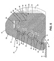
- Figure 5 is a greatly enlarged cross-sectional view of an encircled portion of Figure 4 ;
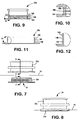
- Figure 6 is an illustration of a set in the method of attaching the bag fitting to a wall of the bag, and is seen in cross sectional side elevation view with the component parts positioned preparatory to assembly;
- Figure 7 is a side elevational view of a second embodiment that is not part of the invention showing in particular an alternate fitting prior to mating engagement and capture of a portion of the wall;
- Figure 8 is a side elevational view of a second embodiment that is not part of the present invention showing in particular an alternate fitting upon mating engagement and capture of a portion of the wall; ,
- Figure 9 is a cross-sectional view of a second embodiment of the outer fitting that is not part of the present invention taken generally about lines 9-9 of Figure 7 ;
- Figure 10 is a greatly enlarged cross-sectional view of an encircled portion of Figure 9 ;
- Figure 11 is a cross-sectional view of a second embodiment of the inner fitting that is not part of the present invention taken generally about lines 11-11 of Figure 7 ;
- Figure 12 is a greatly enlarged cross-sectional view of an encircled portion of Figure 11 .
- FIG. 1 Viewing first Figures 1 and 2 in conjunction with one another for illustrations of a bag-in-box container 10 embodying the present invention, it is seen that this container 10 includes an outer shape-retaining box 12 of corrugated paperboard and an inner flexible bag 14, which is fabricated partly of laminated plastic sheet material.
- the bag 14 includes a pair of generally flat and congruent walls 16 and 18, which are formed of laminated plastic sheet material, and which are sealingly secured to one another at a peripheral seal area 20. Attached to one wall 16 of the bag 14, this bag carries a bag fitting 22 which defines a passage 24 opening into the interior of the bag 14 (i.e., that is, the passage 24 opens into the variable-volume space between the walls 16 and 18).
- the bag fitting 22 defines an outwardly opening groove 26 which is engageable with a wall of the box 12 in order to retain the fitting 22 and a cap/tap 28 is sealingly carried on this fitting at a position external to the box 12 in order to allow dispensing of liquid from within the bag via the cap/tap 28.
- the cap/tap 28 includes a flange portion 30 and a tap handle portion 32, it will be understood that a user of the bag-in-box container 10 may dispense liquid from within the bag 14 via the cap/tap 28 by manually pinching the tap handle portion 32 toward the flange 30 (as is illustrated by arrow 28a).
- the bag fitting 22 includes a generally conical base portion 34 from which extends a neck portion 36 outwardly of the bag 14 and wall 16.
- This neck portion 36 carries a collar portion 38 which is spaced from the base portion 34 so as to cooperate with a shoulder part 40 on the base portion in order to define the groove 26.
- a termination portion 42 of the neck portion includes features such as an outwardly extending lip 44 and an inwardly extending ring or rib 46 (best seen in Figure 4 ) for allowing the cap/tap 28 to be sealingly attached to the bag fitting 22.
- the passage 24 through the bag fitting 22 is cooperatively defined by a bore portion 48 defined by an outer portion 22a of the fitting 22, and by an aligned bore portion 50 of an inner portion 22b of this fitting 22.
- the outer (22a) and inner (22b) portions of the fitting 22 also cooperatively and sealingly capture a peripheral portion 16a of the wall 16 about a circular opening or hole 16b defined by this wall (best seen in Figure 6 ) in order to attach the fitting 22 sealingly to the wall 16.
- the base portion 34 of the fitting portion 22a inwardly defines an annular recess 52.
- This recess 52 is defined cooperatively by an outer generally conical wall portion 54, which outwardly defines the base portion 34, and by an opposed inwardly disposed annular wall portion 56, which itself inwardly defines a portion of the bore 48.
- Received into this recess is an inner peripheral portion 16a of the wall 16 about the opening 16b, and the annular inner fitting portion 22b.
- fitting portions 22a and 22b While additional details of both the outer and inner fitting portions 22a and 22b will be explained below, it is important to understand at this point that the fitting portions are a permanent "snap" fit together, and that they cooperatively capture the portion 16a of wall 16 sealingly in recess 52.
- the wall portion 54 inwardly defines four convergent conical surface sections 58, 60, 62, and 64, interdigitated (or alternated axially) with three divergent conical surface sections 66, 68, and 70.
- the wall sections just identified cooperatively define three successive and axially spaced apart annular rings or "shoulders” 72, 74, and 76 circumscribing the recess 52.
- shoulder 72, 74, and 76 circumscribing the recess 52.
- the terms, "convergent” and “divergent” are considered with respect to the direction of entry of the fitting portion 22b into the recess 52 of the fitting portion 22a, as can be readily understood from a consideration of Figure 6 .
- the term "axial” as used herein refers to the axis of the passage 24, and of bore portions 48 and 50, cooperatively defining this passage.
- fitting portion 22b on its radially outer surface defines three convergent conical surface portions 78, 80, and 82, which are interdigitated with three divergent conical surface portions 84, 86, and 88.
- the convergent and divergent surface portions on fitting member 22b cooperatively define three annular ribs or "crests" 90, 92, and 94 about the fitting member 22b on its radially outer surface.
- the fitting portions 22a and 22b form an axially spaced or disposed series of tapered surface seatings each capturing the wall member 16 at portion 16a between confronting tapered (i.e., conical) surfaces of the fitting portions 22a and 22b.
- the wall portion 16a is engaged sealingly on tapering surfaces both inwardly and outwardly and in a "pinch” applied across the thickness of this wall portion 16a by the opposed tapered conical surfaces of the fitting portions 22a and 22b adjacent to the ribs and rings of these fitting portions.
- the fitting portion 22b defines a stepped through bore 96, a part of which defines the bore 50 and respective part of passage 24.
- the bore 96 includes a larger diameter portion 98.
- the bore portions 50 and 98 cooperatively define a shoulder 100 on the fitting portion 22b.
- the annular wall portion 56 is received into the bore portion 98, and abuts against the shoulder 100.
- the wall portion 56 defines a radially outwardly extending rib 102. This rib 102 is sealingly captured by a corresponding radially inwardly opening groove 104 defined on the bore portion 98 of the fitting portion 22b.
- the cooperation of rib 102 in groove 104 also assists in retaining the fitting portion 22b permanently in the recess 52 of fitting portion 22a.
- the cooperation of the rib 102 and groove 104 defines another sealing engagement of the fitting portions 22a and 22b. That is, the fitting portions 22a and 22b sealingly cooperate with one another via the interposed wall portion 16a, and also sealingly cooperate with one another directly at the rib 102 and groove 104.
- the fitting portion 22b is sealingly and captured and retained both radially inwardly and radially outwardly by the fitting portion 22a. That is, the wall portion 54 captures the fitting portion 22b radially outwardly, and the wall portion 56 captures the fitting portion 22b radially inwardly and engages at rib 102 with the groove 104.
- the fitting 22 is permanently attached to wall 16 of the bag 14 before the walls 16 and 18 are sealingly attached to one another to form the completed bag 22, as is seen in Figure 2 .
- the cap/tap 28 is sealingly attached, and the contents of the closed bag 22 are protected from the environment.
- tap is disposed inside of the box 12, and this box greatly protects the plastic bag 14 from damage. Because the plastic sheet material from which walls 16 and 18 are formed is resistant to or essentially impermeable to penetration by oxygen, the contents of the filled and closed bag 14 are essentially protected against oxygen deterioration since oxygen cannot enter via the walls of the bag.
- the fitting 22 may be fabricated of plastic materials which are resistant to or essentially impermeable to oxygen penetration, the contents of the filled and closed bag 14 are also essentially protected against oxygen deterioration because oxygen cannot enter via the fitting 22.
- the cap/tap 28 is conventionally made of materials preventing oxygen penetration, so it follows that the contents of the filled and closed bag 14 are entirely protected against oxygen penetration from the atmosphere, and will not be deteriorated because of oxygenation regardless of how long the filled bag 14 is stored.
- the conical surfaces are replaced with surfaces which are generally orthogonal to the axial passage 24.
- the outer component 22a includes a plurality of rings 184, 186 and 188.
- the inner component 22b includes a plurality of ribs 158, 160 and 162 which are configured to axially pass the plurality of indentations when the outer and inner components are mated together in a locking configuration, and, in turn, cooperatively capture a portion of a wall therebetween.
- Each of the ribs 158, 160, and 162 includes an inclined upper surface at the extreme distal end.
- the inclined upper surfaces aid relative to passing the respective rings, and thereby achieving mating engagement and the capturing of the wall therebetween.
- the mating engagement requires less force than disengagement.
- the operation of such an embodiment is quite similar relative to the operation of the embodiment shown in Figures 1 through 6 .
- the embodiment of Figures 7 through 12 provides an alternative which may be easier to produce on certain types of equipment.
- the component parts 22a and 22b of the fitting 22 can be, but need not be, made of the same material. That is, these components may be made of materials which have the same or differing coefficients of friction with the wall 16.
- the use of materials with relatively high coefficients of friction may perhaps offer another way of increasing the interbonding of the bag wall 16 with the fitting 22 during the force fitting of the components 22a and 22b together.
- selection of materials with a relatively low coefficient of friction may increase the speed of assembly of the components 22a and 22b with the wall 16a of the bag 16.
- the sealing engagement of the fitting 22 with the wall 16a of bag 16 is not dependent upon either heat sealing nor adhesive sealing. Rather, a plurality of interference fit features and mechanical interlocking of the fitting components and the bag wall is effective to achieve a sealing permanent attachment of the fitting 22 and wall 16a.
- the wall may be preheated prior to assembly of the spout, so as to minimize wrinkles caused by the mating engagement. Accordingly, these other alternatives and modifications are also within the scope of the present invention. And, it follows that the present invention is not limited precisely to or only to that embodiment shown and described herein. Rather, the scope of the appended claims define the scope of the present invention.
Landscapes
- Engineering & Computer Science (AREA)
- Mechanical Engineering (AREA)
- Packages (AREA)
- Making Paper Articles (AREA)
- Closures For Containers (AREA)
- Bag Frames (AREA)
Abstract
Description
- The present invention relates to a bag-in-box container, for receiving, transporting, and dispensing liquids, such as wine, for example. More particularly, the present invention relates to such a bag-in-box container, which has a bag portion essentially impermeable to oxygen. Because oxygen permeation into the contents of conventional bag-in-box containers is undesirable, shortens the shelf life of the container contents, and generally contributes to deterioration and loss of quality of the contents of such conventional containers, the present invention offers a significant improvement. A method of making such a bag and the bag-in-box container is presented also.
- There are many applications in which liquids are received into, transported, and later dispensed from containers. In the case of wine, for example, the glass bottle with a natural or, more recently, an artificial cork, is well known.
- Another common application is known in the commercial consumer market in which wine is packaged in a box-like container made of paper board and having a collapsible inner bag which serves to hold the wine. A tap is attached to the bag by use of a fitting that is sealingly attached to the bag and also sealingly interfaces with the body of the tap. Wine is filled into the bag, and then the cap is added and the filled bag is transported entirely within the box, which serves to protect the bag, and later also serves to hold the bag with the tap protruding through a prepared opening of the box for dispensing the wine.
- Conventional bag-in-box containers generally include a bag which is formed of a thin, flexible plastic sheet material comprising a multi-layer laminate of fine-dimension layers, at least one of which is resistant to permeation by oxygen. The essentially impermeable layer may be made of a metal, such as aluminum, for example. Or, the essentially impermeable layer may be made of polyester.
- However, in order to attach a tap to such a bag, the plastic sheet material includes a facial layer that may be bonded, and the bag is provided with a fitting that may be bonded to the one facial layer of the laminated plastic bag. The spout for closing the fitting, and for dispensing the liquid contents of the bag sealing engages with the fitting.
- In order to be made of a material which will bond to the facial layer of the bag, the bag fitting conventionally must be made of a material which is also undesirably oxygen permeable. The oxygen permeability of the material from which the fitting is made is not a criteria for selecting the material, but instead is an undesirable consequence of the need to select a material that can be bonded to the facial layer of the laminated plastic sheet material. Frequently, the bag fitting and the facial layer are conventionally formed from polyethylene. Because the conventional bag fittings allow a certain amount of oxygen permeation or penetration, the contents of the filled and closed bags are conventionally deteriorated somewhat, with the degree or extent of deterioration depending on the length of storage time, as well as such factors as ambient temperature in the area of storage.
- An alternative type of bag-in-box container uses a bag in which the fitting is adhesively sealed to a bag wall. This type of bag offers speed of manufacture, but generally does not offer a hermetic type of seal between the bag and fitting.
Further bag-in-box containers are known from Au 2823977 and 1396439. - In view of the foregoing an object of the present invention is to overcome one or more of the drawbacks of conventional bag-in-box containers.
- Particularly, it is an object for this invention to provide a bag for such a bag-in-box container, which includes a bag fitting formed of material that is substantially impermeable to oxygen.
- Another object for this invention is to provide a bag for such a bag-in-box container in which the bag need not be bonded to the fitting, but in which the fitting is mechanically and sealingly attached to a wall of the bag.
- Still another object for this invention is to provide a fitting for such a bag-in-box container in which the fitting is made of material which is essentially oxygen impermeable.
- Thus, the present invention provides an oxygen impermeable flexible bag container according to claim 1.
- Particularly, it is to be appreciated that an advantage according to the invention is that the bag fitting sealingly attaches to a wall of the bag mechanically and permanently, without the use of bonding between polymers. Accordingly, the bag fitting forms a mechanical attachment and seal to a wall of the bag, and may be formed of any material that is desired, because polymer bonding of the bag and fitting are not necessary.
- Other objects, features, and advantages of the present invention will become apparent to those skilled in the art from a consideration of the following detailed description taken in conjunction with the accompanying drawings.
-
Figure 1 is a perspective view of an exemplary bag-in-box container, having the liquid-dispensing tap in a position protruding outwardly through a specially prepared opening of the box and locked into this position for dispensing of liquid from the tap; -
Figure 2 is a perspective view of the bag within the bag-in-box container ofFigure 1 , except that the bag as seen inFigure 2 is without the tap, and is empty and not full of liquid; -
Figure 3 is a side elevation view of the bag fitting portion of the bag seen inFigure 2 , along with a portion of the bag wall to which this fitting is sealingly attached; -
Figure 4 is a side elevation view taken at line 4-4 ofFigure 3 ; -
Figure 5 is a greatly enlarged cross-sectional view of an encircled portion ofFigure 4 ; -
Figure 6 is an illustration of a set in the method of attaching the bag fitting to a wall of the bag, and is seen in cross sectional side elevation view with the component parts positioned preparatory to assembly; -
Figure 7 is a side elevational view of a second embodiment that is not part of the invention showing in particular an alternate fitting prior to mating engagement and capture of a portion of the wall; -
Figure 8 is a side elevational view of a second embodiment that is not part of the present invention showing in particular an alternate fitting upon mating engagement and capture of a portion of the wall; , -
Figure 9 is a cross-sectional view of a second embodiment of the outer fitting that is not part of the present invention taken generally about lines 9-9 ofFigure 7 ; -
Figure 10 is a greatly enlarged cross-sectional view of an encircled portion ofFigure 9 ; -
Figure 11 is a cross-sectional view of a second embodiment of the inner fitting that is not part of the present invention taken generally about lines 11-11 ofFigure 7 ; and -
Figure 12 is a greatly enlarged cross-sectional view of an encircled portion ofFigure 11 . - Viewing first
Figures 1 and 2 in conjunction with one another for illustrations of a bag-in-box container 10 embodying the present invention, it is seen that thiscontainer 10 includes an outer shape-retainingbox 12 of corrugated paperboard and an innerflexible bag 14, which is fabricated partly of laminated plastic sheet material. AsFigure 2 illustrates, thebag 14 includes a pair of generally flat andcongruent walls peripheral seal area 20. Attached to onewall 16 of thebag 14, this bag carries abag fitting 22 which defines apassage 24 opening into the interior of the bag 14 (i.e., that is, thepassage 24 opens into the variable-volume space between thewalls 16 and 18). - While the bag fitting 22 will be further explained below, it is sufficient at this point to note on
Figures 1 and 2 that thebag fitting 22 defines an outwardlyopening groove 26 which is engageable with a wall of thebox 12 in order to retain thefitting 22 and a cap/tap 28 is sealingly carried on this fitting at a position external to thebox 12 in order to allow dispensing of liquid from within the bag via the cap/tap 28. Noting onFigure 1 , that the cap/tap 28 includes aflange portion 30 and atap handle portion 32, it will be understood that a user of the bag-in-box container 10 may dispense liquid from within thebag 14 via the cap/tap 28 by manually pinching thetap handle portion 32 toward the flange 30 (as is illustrated by arrow 28a). - Referring more particularly now to
Figures 3, 4 , and5 in conjunction with one another, it is seen that the bag fitting 22 includes a generallyconical base portion 34 from which extends aneck portion 36 outwardly of thebag 14 andwall 16. Thisneck portion 36 carries acollar portion 38 which is spaced from thebase portion 34 so as to cooperate with ashoulder part 40 on the base portion in order to define thegroove 26. Atermination portion 42 of the neck portion includes features such as an outwardly extendinglip 44 and an inwardly extending ring or rib 46 (best seen inFigure 4 ) for allowing the cap/tap 28 to be sealingly attached to thebag fitting 22. - As is best appreciated viewing
Figures 4 and5 in conjunction with one another, thepassage 24 through thebag fitting 22 is cooperatively defined by abore portion 48 defined by anouter portion 22a of thefitting 22, and by analigned bore portion 50 of aninner portion 22b of thisfitting 22. The outer (22a) and inner (22b) portions of thefitting 22 also cooperatively and sealingly capture aperipheral portion 16a of thewall 16 about a circular opening orhole 16b defined by this wall (best seen inFigure 6 ) in order to attach thefitting 22 sealingly to thewall 16. - Turning to
Figures 5 and6 in conjunction with one another, it is seen that thebase portion 34 of thefitting portion 22a inwardly defines anannular recess 52. Thisrecess 52 is defined cooperatively by an outer generallyconical wall portion 54, which outwardly defines thebase portion 34, and by an opposed inwardly disposedannular wall portion 56, which itself inwardly defines a portion of thebore 48. Received into this recess, as is seen best inFigure 5 , is an innerperipheral portion 16a of thewall 16 about the opening 16b, and the annularinner fitting portion 22b. While additional details of both the outer and innerfitting portions portion 16a ofwall 16 sealingly inrecess 52. - Considering now
Figures 5 and6 in detail, it is seen that thewall portion 54 inwardly defines four convergentconical surface sections conical surface sections 66, 68, and 70. The wall sections just identified cooperatively define three successive and axially spaced apart annular rings or "shoulders" 72, 74, and 76 circumscribing therecess 52. In this case, the terms, "convergent" and "divergent" are considered with respect to the direction of entry of thefitting portion 22b into therecess 52 of thefitting portion 22a, as can be readily understood from a consideration ofFigure 6 . The term "axial" as used herein refers to the axis of thepassage 24, and ofbore portions - Also, and similarly, the
fitting portion 22b on its radially outer surface defines three convergentconical surface portions conical surface portions member 22b cooperatively define three annular ribs or "crests" 90, 92, and 94 about thefitting member 22b on its radially outer surface. As is seen inFigure 5 , when thefitting portions wall 16 atopening 16b, and thefitting portion 22b is forced into recess 52 (as is indicated by force and movement arrows onFigure 6 ), theperipheral wall portion 16a is captured about thefitting portion 22b, and is forced into therecess 52 along with thefitting portion 22b. Consequently, the edge of thewall 16 atopening 16b is sealingly protected from exposure to the ambient, and from exposure to any product or material placed into thebag 14. It will be understood that theribs fitting portion 22b are forced inwardly (that is, axially) of therecess 52 past the corresponding rings 72, 74, and 76 of thefitting portion 22a. Once each rib axially passes its corresponding ring, thefitting portion 22b is permanently and sealingly captured withinrecess 52 offitting portion 22a. - Consequently, the
fitting portions wall member 16 atportion 16a between confronting tapered (i.e., conical) surfaces of thefitting portions wall portion 16a is engaged sealingly on tapering surfaces both inwardly and outwardly and in a "pinch" applied across the thickness of thiswall portion 16a by the opposed tapered conical surfaces of thefitting portions portion 16a ofwall 16, and three corresponding sealing engagement on the outside of this wall) of the fitting 22 with thewall 16 at theperipheral portion 16a surrounding opening 16b. - Further to the above, it will be seen viewing
Figure 5 , that thefitting portion 22b defines a stepped throughbore 96, a part of which defines thebore 50 and respective part ofpassage 24. On the other hand, thebore 96 includes alarger diameter portion 98. Thebore portions shoulder 100 on thefitting portion 22b. As is seen inFigure 5 , theannular wall portion 56 is received into thebore portion 98, and abuts against theshoulder 100. Further, thewall portion 56 defines a radially outwardly extendingrib 102. Thisrib 102 is sealingly captured by a corresponding radially inwardly openinggroove 104 defined on thebore portion 98 of thefitting portion 22b. It will be appreciated the cooperation ofrib 102 ingroove 104 also assists in retaining thefitting portion 22b permanently in therecess 52 offitting portion 22a. Also, the cooperation of therib 102 and groove 104 defines another sealing engagement of thefitting portions fitting portions wall portion 16a, and also sealingly cooperate with one another directly at therib 102 andgroove 104. Stated differently, it is seen that thefitting portion 22b is sealingly and captured and retained both radially inwardly and radially outwardly by thefitting portion 22a. That is, thewall portion 54 captures thefitting portion 22b radially outwardly, and thewall portion 56 captures thefitting portion 22b radially inwardly and engages atrib 102 with thegroove 104. - In view of the above, it is to be appreciated that the fitting 22 is permanently attached to wall 16 of the
bag 14 before thewalls bag 22, as is seen inFigure 2 . Later, after filling of thebag 22, the cap/tap 28 is sealingly attached, and the contents of theclosed bag 22 are protected from the environment. During shipping, handling, and storage of thebag 22, tap is disposed inside of thebox 12, and this box greatly protects theplastic bag 14 from damage. Because the plastic sheet material from whichwalls bag 14 are essentially protected against oxygen deterioration since oxygen cannot enter via the walls of the bag. Similarly, because the fitting 22 may be fabricated of plastic materials which are resistant to or essentially impermeable to oxygen penetration, the contents of the filled and closedbag 14 are also essentially protected against oxygen deterioration because oxygen cannot enter via the fitting 22. The cap/tap 28 is conventionally made of materials preventing oxygen penetration, so it follows that the contents of the filled and closedbag 14 are entirely protected against oxygen penetration from the atmosphere, and will not be deteriorated because of oxygenation regardless of how long the filledbag 14 is stored. - In another embodiment that is not part of the invention, shown in
Figures 7 through 12 , the conical surfaces are replaced with surfaces which are generally orthogonal to theaxial passage 24. Specifically, theouter component 22a includes a plurality ofrings inner component 22b includes a plurality ofribs ribs Figures 1 through 6 . The embodiment ofFigures 7 through 12 provides an alternative which may be easier to produce on certain types of equipment. - Those skilled in the art will understand that the preceding exemplary embodiment of the present invention provides the foundation for numerous alternatives and modifications thereto. For example, it is apparent that the
component parts wall 16. The use of materials with relatively high coefficients of friction may perhaps offer another way of increasing the interbonding of thebag wall 16 with the fitting 22 during the force fitting of thecomponents components wall 16a of thebag 16. In each case, the sealing engagement of the fitting 22 with thewall 16a ofbag 16 is not dependent upon either heat sealing nor adhesive sealing. Rather, a plurality of interference fit features and mechanical interlocking of the fitting components and the bag wall is effective to achieve a sealing permanent attachment of the fitting 22 andwall 16a. It will be understood that the wall may be preheated prior to assembly of the spout, so as to minimize wrinkles caused by the mating engagement. Accordingly, these other alternatives and modifications are also within the scope of the present invention. And, it follows that the present invention is not limited precisely to or only to that embodiment shown and described herein. Rather, the scope of the appended claims define the scope of the present invention.
Claims (6)
- An oxygen impermeable flexible bag container (10) including an essentially oxygen impermeable flexible bag wall (16. 18) bounding a variable-volume chamber, and an essentially oxygen impermeable bag fitting structure (22) sealingly attaching to a fine dimension flexible wall (16) of said bag (14), without heat sealing or adhesive, and defining a passage (24) communicating with said variable-volume chamber, said bag container (10) comprising; a flexible and essentially oxygen impermeable wall (16, 18) circumscribing and defining a variable volume chamber, an essentially oxygen impermeable fitting (22) for sealingly attaching to said wall and defining a passage (24) for communicating between said variable-volume chamber and ambient; said flexible wall (16) defining a hole opening (16b) to said variable-volume chamber, and including a peripheral portion circumscribing (16a) said hole (16b) ; said fitting structure (22) including a pair of fitting parts (22a, 22b) disposed on opposite side of said wall (16) and each sealingly engaging said peripheral portion; each of said pair of fitting parts (22a, 22b) defining respective interference fit features sealingly cooperable with said peripheral wall portion (16) and with a corresponding interference fit feature of the other of said pair of fitting parts 22a, 22b), wherein an outer fitting (22a) of said pair of fitting parts (22a, 22b) includes a central bore (48), a neck portion (36) structurally configured to receive a cap or tap (28) and a base portion (34) having an inwardly annular recess (52), and a inner fitting (22b) of said pair of fitting parts (22a, 22b) including a central bore (50) and a radial outward surface opposite said central bore (50), wherein the radial outward surface of the inner fitting (22b) is attachable to the inwardly annular recess (52) of the outer fitting (22a) and the radial outward surface of the second fitting (22b) and the inwardly annular recess (52) of the first fitting (22a) cooperate, to in turn, capture the bag therebetween, and wherein said outer one fitting part (22a) defines a radially inner wall portion (56) inwardly bounding said passage (24) and outwardly bounding said recess (52), and said outer one fitting part (22a) also defines a radially outer wall portion (54) outwardly bounding said recess (52); said inner fitting portion (22b) being received into said recess (52) between said inner wall portion and said outer wall portion.
- The oxygen impermeable flexible bag container of claim 1 wherein said pair of fitting parts (22a. 22b) defines a cavity disposed in said recess (52) and radially between said inner wall portion and said outer wall portion, and said pair of fitting parts (22a, 22b) cooperatively sealingly trapping an end edge of said flexible wall (16) at a hole (16a) thereof about said passage (24) in said cavity.
- The oxygen impermeable flexible bag container of claim 1 wherein said at least one pair of interference fit features includes said outer one of said pair of fitting parts (22a, 22b) defining a wall surface circumscribing a recess (52), and said wall surface inwardly defining at least one convergent female surface section leading to at least one divergent female surface section; said convergent and divergent female surface sections intersecting to form a shoulder (72, 74, 76) circumscribing said recess; and said inner (22b) of said pair of fitting parts (22a, 22b) defining an outwardly disposed wall surface for being received into said recess (52), said other fitting part (22b) similarly outwardly defining at least one convergent male surface portion leading to at least one divergent male surface portion; said convergent and divergent conical male surface portions intersecting to form a rib (90, 92, 94) circumscribing said wall surface of said other fitting part (22b); and said rib and said shoulder cooperatively forming an interference fit with said flexible wall (16) interposed therebetween.
- The oxygen impermeable flexible bag container of claim 3 wherein each of said pair of fitting parts (22a, 22b) defines plural pairs of interference fit features arranged axially along said recess.
- The oxygen impermeable flexible bag container of claim 1 wherein the outer one of said pair of fitting parts (22a, 22b) defines a conical wall surface inwardly define a recess (52) and plural convergent conical female surface sections disposed along said recess; and a multitude of cooperative divergent conical female surface sections interdigitated with said plural convergent conical female surface sections, and said convergent and divergent conical female surface sections cooperatively defining a number of successive and axially spaced apart annular female rings circumscribing said recess; said inner one (22b) of said pair of fitting parts (22a, 22b) defining a radially outer conical male surface defining plural convergent conical male surface portions; a multitude of divergent conical male surface portions interdigitating with said plural convergent conical male surface portions: and said convergent and divergent male surface portions on said inner fitting part (22b) cooperatively defining a number of annular ribs about said inner fitting part (22b): whereby said pair of fitting parts (22a. 22b) engage with said wall (16) at the hole (16a) and forcibly dispose a peripheral portion of said wall (16) into said recess (52) and about said inner fitting part (22b), so that each rib is forced axially past a corresponding ring and sealingly pinches said wall between said inner and said outer fitting parts (22a, 22b).
- The oxygen impermeable flexible bag container of claim 1 including an essentially oxygen impermeable flexible bag wall (16, 18) bounding a variable-volume chamber, and an essentially oxygen impermeable bag fitting structure (22) sealingly attaching to said bag wall (16) and defining a passage (24) communicating with said variable-volume chamber, said bag container (10) comprising; a flexible essentially oxygen impermeable wall (16, 18) circumscribing and defining a variable volume chamber, said wall including a peripheral portion circumscribing a hole communicating between said variable-volume chamber and ambient; an essentially oxygen impermeable fitting for sealingly attaching to said wall and defining a passage (24) for communicating between said variable-volume chamber and ambient; said fitting (22) including a pair of fitting parts (22a, 22b) disposed on opposite sides of said wall (16) and each sealingly engaging said peripheral portion; and said peripheral wall portion extending axially between said pair of fitting parts (22a, 22b) and outwardly of said passage, wherein an outer fitting of said pair of fitting parts (22a, 22b) includes a central bore (48), a neck portion (36) structurally configured to receive a cap or tap (28) and a base portion (34) extending around said peripheral portion of the wall (16) on an outer side thereof, the base portion (34) having an inwardly annular recess (52), and an inner fitting (22b) of said pair of fittings (22a, 22b) including a central bore (50) and a radial outward surface opposite said central bore (50), with the radial outward surface extending around said peripheral portion of the wall on an inner side thereof, wherein the outer fitting (22a) extends about the inner fitting (22b), and the radial outward surface of the inner fitting (22b) and the inwardly annular recess (52) of the outer fitting (22a) cooperate, to in turn, capture the bag therebetween.
Applications Claiming Priority (2)
| Application Number | Priority Date | Filing Date | Title |
|---|---|---|---|
| US10/983,508 US20060110077A1 (en) | 2004-11-06 | 2004-11-06 | Oxygen impermeable bag-in-box container and methof of making |
| PCT/US2005/040156 WO2006052817A2 (en) | 2004-11-06 | 2005-11-07 | Oxygen impermeable bag-in-box container and method of making |
Publications (3)
| Publication Number | Publication Date |
|---|---|
| EP1814796A2 EP1814796A2 (en) | 2007-08-08 |
| EP1814796A4 EP1814796A4 (en) | 2009-08-05 |
| EP1814796B1 true EP1814796B1 (en) | 2011-03-30 |
Family
ID=36337063
Family Applications (1)
| Application Number | Title | Priority Date | Filing Date |
|---|---|---|---|
| EP05817173A Expired - Lifetime EP1814796B1 (en) | 2004-11-06 | 2005-11-07 | Oxygen impermeable flexible bag container |
Country Status (7)
| Country | Link |
|---|---|
| US (1) | US20060110077A1 (en) |
| EP (1) | EP1814796B1 (en) |
| AT (1) | ATE503695T1 (en) |
| AU (1) | AU2005304870A1 (en) |
| CA (1) | CA2593120A1 (en) |
| DE (1) | DE602005027238D1 (en) |
| WO (1) | WO2006052817A2 (en) |
Families Citing this family (8)
| Publication number | Priority date | Publication date | Assignee | Title |
|---|---|---|---|---|
| US7770360B2 (en) * | 2005-12-05 | 2010-08-10 | Ds Smith Plastics Limited | Form fill and seal container |
| US20090020183A1 (en) * | 2007-02-21 | 2009-01-22 | Terence Edward Denis Kelly | Flexible tanks for transporting bulk products |
| US9957148B2 (en) * | 2009-09-14 | 2018-05-01 | Pouch Pac Innovations, Llc | Pouch with a tube spout fitment |
| US8956046B2 (en) * | 2010-11-22 | 2015-02-17 | Hosokawa Yoko Co., Ltd. | Bag with port member and connection structure thereof |
| WO2012109693A1 (en) * | 2011-02-17 | 2012-08-23 | Marmalo Pty Ltd | Bulk transportation of water |
| CN110891693B (en) * | 2017-07-14 | 2022-07-01 | 3M创新有限公司 | Fluid delivery assembly for spray gun |
| FR3102698B1 (en) * | 2019-11-05 | 2023-03-03 | Abc Transfer | WATERPROOF CONTAINER COMPRISING A DEVICE FOR REMOVABLE CONNECTION TO A SPEAKER |
| FR3105186B1 (en) * | 2019-12-20 | 2021-11-12 | Abc Transfer | WATERPROOF CONTAINER INCLUDING A DEVICE ALLOWING REMOVABLE CONNECTION TO A SPEAKER |
Family Cites Families (12)
| Publication number | Priority date | Publication date | Assignee | Title |
|---|---|---|---|---|
| US1340236A (en) * | 1920-01-05 | 1920-05-18 | Moehle Walter | Hot-water or ice bag |
| US1994127A (en) * | 1933-10-31 | 1935-03-12 | Goodrich Co B F | Water bottle |
| US2374796A (en) * | 1942-05-18 | 1945-05-01 | Universal Paper Products Compa | Collapsible container |
| US3212681A (en) * | 1963-10-09 | 1965-10-19 | Gen Films Inc | Container structure |
| US3656668A (en) * | 1969-09-11 | 1972-04-18 | Container Corp | Neck assembly for thin walled container |
| US3783920A (en) * | 1972-06-20 | 1974-01-08 | Gen Films Inc | Container and closure therefor |
| US4028156A (en) * | 1974-08-19 | 1977-06-07 | Plastronics, Inc. | Plastic container and closure collar combination and method |
| AU2823977A (en) * | 1976-08-30 | 1979-03-01 | Vynol Paints Pty Ltd | Container dispensing means |
| CN1111494C (en) * | 1997-03-12 | 2003-06-18 | H·奥布里斯特股份公司 | bag tube |
| EP0928747A3 (en) * | 1997-12-23 | 1999-08-04 | Karl Bösch Engineering | Method for making a deformable container, and container made according to this method |
| US7066337B2 (en) * | 2002-01-05 | 2006-06-27 | Hsu Wei K Lou | Reusable filter port assembly for installation on the wall of a bag |
| US20040051189A1 (en) * | 2002-09-04 | 2004-03-18 | Meier Terrence P. | Two material over-molded fitment |
-
2004
- 2004-11-06 US US10/983,508 patent/US20060110077A1/en not_active Abandoned
-
2005
- 2005-11-07 EP EP05817173A patent/EP1814796B1/en not_active Expired - Lifetime
- 2005-11-07 WO PCT/US2005/040156 patent/WO2006052817A2/en not_active Ceased
- 2005-11-07 AU AU2005304870A patent/AU2005304870A1/en not_active Abandoned
- 2005-11-07 DE DE602005027238T patent/DE602005027238D1/en not_active Expired - Lifetime
- 2005-11-07 AT AT05817173T patent/ATE503695T1/en not_active IP Right Cessation
- 2005-11-07 CA CA002593120A patent/CA2593120A1/en not_active Abandoned
Also Published As
| Publication number | Publication date |
|---|---|
| US20060110077A1 (en) | 2006-05-25 |
| ATE503695T1 (en) | 2011-04-15 |
| AU2005304870A1 (en) | 2006-05-18 |
| WO2006052817A2 (en) | 2006-05-18 |
| DE602005027238D1 (en) | 2011-05-12 |
| WO2006052817A3 (en) | 2007-04-12 |
| CA2593120A1 (en) | 2006-05-18 |
| WO2006052817B1 (en) | 2007-05-18 |
| EP1814796A2 (en) | 2007-08-08 |
| EP1814796A4 (en) | 2009-08-05 |
Similar Documents
| Publication | Publication Date | Title |
|---|---|---|
| JP2938784B2 (en) | Plastic fastener | |
| EP0471503B1 (en) | Fluid dispenser | |
| EP3995409B1 (en) | Container | |
| US11142377B2 (en) | Easy to remove cap design | |
| US20120258212A1 (en) | Packaged Roast and Ground Coffee | |
| US20060037968A1 (en) | Container with inliner bag and one-way dispenser valve | |
| EP1676784A1 (en) | Flexible container containing a liquid product, and a process for making a liquid-filled, flexible container | |
| US6179173B1 (en) | Bib spout with evacuation channels | |
| US7004209B2 (en) | Flexible mounting for evacuation channel | |
| US20060110077A1 (en) | Oxygen impermeable bag-in-box container and methof of making | |
| EP2902336A1 (en) | A membrane, and a neck including such membrane | |
| US20110110750A1 (en) | Degassing container | |
| EP3841032B1 (en) | Fold and seal flexible valves | |
| CN113056426B (en) | Dispensing closures for containers | |
| JPH10310173A (en) | Container with interior bag | |
| WO1994006695A1 (en) | A closure for sacks, bags or the like containers | |
| EP1862395A1 (en) | Condiment dispenser with collapsible spout | |
| JP3935537B2 (en) | Spout with pilfer-proof properties | |
| JP4549489B2 (en) | Outlet association | |
| US20050211730A1 (en) | Valve for a flexible container | |
| JP2001328675A (en) | Inner bag for metal can | |
| WO2015022686A1 (en) | Dispensing assemblies and containers fitted with the same | |
| US20250353654A1 (en) | Isolated pressurization system and bag configuration | |
| US4533071A (en) | Dispensing closure valve | |
| JP2008018978A (en) | Outlet seal structure for bag-in-box and bag-in-box including the same |
Legal Events
| Date | Code | Title | Description |
|---|---|---|---|
| PUAI | Public reference made under article 153(3) epc to a published international application that has entered the european phase |
Free format text: ORIGINAL CODE: 0009012 |
|
| 17P | Request for examination filed |
Effective date: 20070606 |
|
| AK | Designated contracting states |
Kind code of ref document: A2 Designated state(s): AT BE BG CH CY CZ DE DK EE ES FI FR GB GR HU IE IS IT LI LT LU LV MC NL PL PT RO SE SI SK TR |
|
| AX | Request for extension of the european patent |
Extension state: AL BA HR MK YU |
|
| RIN1 | Information on inventor provided before grant (corrected) |
Inventor name: HSU, JOE Inventor name: HARTMAN, LUKE Inventor name: SAVAGE, CHESTER Inventor name: VERESPEJ, ROCKLIN |
|
| DAX | Request for extension of the european patent (deleted) | ||
| A4 | Supplementary search report drawn up and despatched |
Effective date: 20090707 |
|
| RIC1 | Information provided on ipc code assigned before grant |
Ipc: B65D 33/16 20060101AFI20060929BHEP Ipc: B65D 75/58 20060101ALI20090701BHEP |
|
| 17Q | First examination report despatched |
Effective date: 20091006 |
|
| GRAP | Despatch of communication of intention to grant a patent |
Free format text: ORIGINAL CODE: EPIDOSNIGR1 |
|
| RTI1 | Title (correction) |
Free format text: OXYGEN IMPERMEABLE FLEXIBLE BAG CONTAINER |
|
| GRAS | Grant fee paid |
Free format text: ORIGINAL CODE: EPIDOSNIGR3 |
|
| GRAA | (expected) grant |
Free format text: ORIGINAL CODE: 0009210 |
|
| AK | Designated contracting states |
Kind code of ref document: B1 Designated state(s): AT BE BG CH CY CZ DE DK EE ES FI FR GB GR HU IE IS IT LI LT LU LV MC NL PL PT RO SE SI SK TR |
|
| REG | Reference to a national code |
Ref country code: GB Ref legal event code: FG4D |
|
| REG | Reference to a national code |
Ref country code: CH Ref legal event code: EP |
|
| REG | Reference to a national code |
Ref country code: IE Ref legal event code: FG4D |
|
| REF | Corresponds to: |
Ref document number: 602005027238 Country of ref document: DE Date of ref document: 20110512 Kind code of ref document: P |
|
| REG | Reference to a national code |
Ref country code: DE Ref legal event code: R096 Ref document number: 602005027238 Country of ref document: DE Effective date: 20110512 |
|
| REG | Reference to a national code |
Ref country code: NL Ref legal event code: VDEP Effective date: 20110330 |
|
| PG25 | Lapsed in a contracting state [announced via postgrant information from national office to epo] |
Ref country code: LV Free format text: LAPSE BECAUSE OF FAILURE TO SUBMIT A TRANSLATION OF THE DESCRIPTION OR TO PAY THE FEE WITHIN THE PRESCRIBED TIME-LIMIT Effective date: 20110330 Ref country code: LT Free format text: LAPSE BECAUSE OF FAILURE TO SUBMIT A TRANSLATION OF THE DESCRIPTION OR TO PAY THE FEE WITHIN THE PRESCRIBED TIME-LIMIT Effective date: 20110330 Ref country code: SE Free format text: LAPSE BECAUSE OF FAILURE TO SUBMIT A TRANSLATION OF THE DESCRIPTION OR TO PAY THE FEE WITHIN THE PRESCRIBED TIME-LIMIT Effective date: 20110330 Ref country code: GR Free format text: LAPSE BECAUSE OF FAILURE TO SUBMIT A TRANSLATION OF THE DESCRIPTION OR TO PAY THE FEE WITHIN THE PRESCRIBED TIME-LIMIT Effective date: 20110701 |
|
| LTIE | Lt: invalidation of european patent or patent extension |
Effective date: 20110330 |
|
| PG25 | Lapsed in a contracting state [announced via postgrant information from national office to epo] |
Ref country code: FI Free format text: LAPSE BECAUSE OF FAILURE TO SUBMIT A TRANSLATION OF THE DESCRIPTION OR TO PAY THE FEE WITHIN THE PRESCRIBED TIME-LIMIT Effective date: 20110330 Ref country code: SI Free format text: LAPSE BECAUSE OF FAILURE TO SUBMIT A TRANSLATION OF THE DESCRIPTION OR TO PAY THE FEE WITHIN THE PRESCRIBED TIME-LIMIT Effective date: 20110330 Ref country code: CY Free format text: LAPSE BECAUSE OF FAILURE TO SUBMIT A TRANSLATION OF THE DESCRIPTION OR TO PAY THE FEE WITHIN THE PRESCRIBED TIME-LIMIT Effective date: 20110330 Ref country code: AT Free format text: LAPSE BECAUSE OF FAILURE TO SUBMIT A TRANSLATION OF THE DESCRIPTION OR TO PAY THE FEE WITHIN THE PRESCRIBED TIME-LIMIT Effective date: 20110330 |
|
| PG25 | Lapsed in a contracting state [announced via postgrant information from national office to epo] |
Ref country code: BE Free format text: LAPSE BECAUSE OF FAILURE TO SUBMIT A TRANSLATION OF THE DESCRIPTION OR TO PAY THE FEE WITHIN THE PRESCRIBED TIME-LIMIT Effective date: 20110330 |
|
| PG25 | Lapsed in a contracting state [announced via postgrant information from national office to epo] |
Ref country code: EE Free format text: LAPSE BECAUSE OF FAILURE TO SUBMIT A TRANSLATION OF THE DESCRIPTION OR TO PAY THE FEE WITHIN THE PRESCRIBED TIME-LIMIT Effective date: 20110330 Ref country code: PT Free format text: LAPSE BECAUSE OF FAILURE TO SUBMIT A TRANSLATION OF THE DESCRIPTION OR TO PAY THE FEE WITHIN THE PRESCRIBED TIME-LIMIT Effective date: 20110801 |
|
| PG25 | Lapsed in a contracting state [announced via postgrant information from national office to epo] |
Ref country code: ES Free format text: LAPSE BECAUSE OF FAILURE TO SUBMIT A TRANSLATION OF THE DESCRIPTION OR TO PAY THE FEE WITHIN THE PRESCRIBED TIME-LIMIT Effective date: 20110711 Ref country code: SK Free format text: LAPSE BECAUSE OF FAILURE TO SUBMIT A TRANSLATION OF THE DESCRIPTION OR TO PAY THE FEE WITHIN THE PRESCRIBED TIME-LIMIT Effective date: 20110330 Ref country code: RO Free format text: LAPSE BECAUSE OF FAILURE TO SUBMIT A TRANSLATION OF THE DESCRIPTION OR TO PAY THE FEE WITHIN THE PRESCRIBED TIME-LIMIT Effective date: 20110330 Ref country code: CZ Free format text: LAPSE BECAUSE OF FAILURE TO SUBMIT A TRANSLATION OF THE DESCRIPTION OR TO PAY THE FEE WITHIN THE PRESCRIBED TIME-LIMIT Effective date: 20110330 Ref country code: IS Free format text: LAPSE BECAUSE OF FAILURE TO SUBMIT A TRANSLATION OF THE DESCRIPTION OR TO PAY THE FEE WITHIN THE PRESCRIBED TIME-LIMIT Effective date: 20110730 |
|
| PG25 | Lapsed in a contracting state [announced via postgrant information from national office to epo] |
Ref country code: NL Free format text: LAPSE BECAUSE OF FAILURE TO SUBMIT A TRANSLATION OF THE DESCRIPTION OR TO PAY THE FEE WITHIN THE PRESCRIBED TIME-LIMIT Effective date: 20110330 |
|
| PLBE | No opposition filed within time limit |
Free format text: ORIGINAL CODE: 0009261 |
|
| STAA | Information on the status of an ep patent application or granted ep patent |
Free format text: STATUS: NO OPPOSITION FILED WITHIN TIME LIMIT |
|
| PG25 | Lapsed in a contracting state [announced via postgrant information from national office to epo] |
Ref country code: DK Free format text: LAPSE BECAUSE OF FAILURE TO SUBMIT A TRANSLATION OF THE DESCRIPTION OR TO PAY THE FEE WITHIN THE PRESCRIBED TIME-LIMIT Effective date: 20110330 Ref country code: PL Free format text: LAPSE BECAUSE OF FAILURE TO SUBMIT A TRANSLATION OF THE DESCRIPTION OR TO PAY THE FEE WITHIN THE PRESCRIBED TIME-LIMIT Effective date: 20110330 |
|
| 26N | No opposition filed |
Effective date: 20120102 |
|
| REG | Reference to a national code |
Ref country code: DE Ref legal event code: R097 Ref document number: 602005027238 Country of ref document: DE Effective date: 20120102 |
|
| PG25 | Lapsed in a contracting state [announced via postgrant information from national office to epo] |
Ref country code: IT Free format text: LAPSE BECAUSE OF FAILURE TO SUBMIT A TRANSLATION OF THE DESCRIPTION OR TO PAY THE FEE WITHIN THE PRESCRIBED TIME-LIMIT Effective date: 20110330 |
|
| PG25 | Lapsed in a contracting state [announced via postgrant information from national office to epo] |
Ref country code: MC Free format text: LAPSE BECAUSE OF NON-PAYMENT OF DUE FEES Effective date: 20111130 |
|
| REG | Reference to a national code |
Ref country code: CH Ref legal event code: PL |
|
| GBPC | Gb: european patent ceased through non-payment of renewal fee |
Effective date: 20111107 |
|
| PG25 | Lapsed in a contracting state [announced via postgrant information from national office to epo] |
Ref country code: CH Free format text: LAPSE BECAUSE OF NON-PAYMENT OF DUE FEES Effective date: 20111130 Ref country code: LI Free format text: LAPSE BECAUSE OF NON-PAYMENT OF DUE FEES Effective date: 20111130 |
|
| REG | Reference to a national code |
Ref country code: FR Ref legal event code: ST Effective date: 20120731 |
|
| REG | Reference to a national code |
Ref country code: IE Ref legal event code: MM4A |
|
| REG | Reference to a national code |
Ref country code: DE Ref legal event code: R119 Ref document number: 602005027238 Country of ref document: DE Effective date: 20120601 |
|
| PG25 | Lapsed in a contracting state [announced via postgrant information from national office to epo] |
Ref country code: GB Free format text: LAPSE BECAUSE OF NON-PAYMENT OF DUE FEES Effective date: 20111107 Ref country code: IE Free format text: LAPSE BECAUSE OF NON-PAYMENT OF DUE FEES Effective date: 20111107 |
|
| PG25 | Lapsed in a contracting state [announced via postgrant information from national office to epo] |
Ref country code: FR Free format text: LAPSE BECAUSE OF NON-PAYMENT OF DUE FEES Effective date: 20111130 |
|
| PG25 | Lapsed in a contracting state [announced via postgrant information from national office to epo] |
Ref country code: LU Free format text: LAPSE BECAUSE OF NON-PAYMENT OF DUE FEES Effective date: 20111107 |
|
| PG25 | Lapsed in a contracting state [announced via postgrant information from national office to epo] |
Ref country code: BG Free format text: LAPSE BECAUSE OF FAILURE TO SUBMIT A TRANSLATION OF THE DESCRIPTION OR TO PAY THE FEE WITHIN THE PRESCRIBED TIME-LIMIT Effective date: 20110630 Ref country code: DE Free format text: LAPSE BECAUSE OF NON-PAYMENT OF DUE FEES Effective date: 20120601 |
|
| PG25 | Lapsed in a contracting state [announced via postgrant information from national office to epo] |
Ref country code: TR Free format text: LAPSE BECAUSE OF FAILURE TO SUBMIT A TRANSLATION OF THE DESCRIPTION OR TO PAY THE FEE WITHIN THE PRESCRIBED TIME-LIMIT Effective date: 20110330 |
|
| PG25 | Lapsed in a contracting state [announced via postgrant information from national office to epo] |
Ref country code: HU Free format text: LAPSE BECAUSE OF FAILURE TO SUBMIT A TRANSLATION OF THE DESCRIPTION OR TO PAY THE FEE WITHIN THE PRESCRIBED TIME-LIMIT Effective date: 20110330 |