EP1814286A2 - Dynamic sliding module and uses thereof - Google Patents
Dynamic sliding module and uses thereof Download PDFInfo
- Publication number
- EP1814286A2 EP1814286A2 EP07100023A EP07100023A EP1814286A2 EP 1814286 A2 EP1814286 A2 EP 1814286A2 EP 07100023 A EP07100023 A EP 07100023A EP 07100023 A EP07100023 A EP 07100023A EP 1814286 A2 EP1814286 A2 EP 1814286A2
- Authority
- EP
- European Patent Office
- Prior art keywords
- slide
- dynamic
- track
- opening
- electronic
- Prior art date
- Legal status (The legal status is an assumption and is not a legal conclusion. Google has not performed a legal analysis and makes no representation as to the accuracy of the status listed.)
- Granted
Links
Images


Classifications
-
- H—ELECTRICITY
- H04—ELECTRIC COMMUNICATION TECHNIQUE
- H04M—TELEPHONIC COMMUNICATION
- H04M1/00—Substation equipment, e.g. for use by subscribers
- H04M1/02—Constructional features of telephone sets
- H04M1/0202—Portable telephone sets, e.g. cordless phones, mobile phones or bar type handsets
- H04M1/0206—Portable telephones comprising a plurality of mechanically joined movable body parts, e.g. hinged housings
- H04M1/0208—Portable telephones comprising a plurality of mechanically joined movable body parts, e.g. hinged housings characterized by the relative motions of the body parts
- H04M1/0235—Slidable or telescopic telephones, i.e. with a relative translation movement of the body parts; Telephones using a combination of translation and other relative motions of the body parts
- H04M1/0237—Sliding mechanism with one degree of freedom
Definitions
- the present invention generally relates to a dynamic sliding module for an electronic device. More particularly, this invention relates to a magnetically dynamic sliding module for an electronic device.
- mobile phone manufacturers are working extremely hard to increase mobile phone functions in order to satisfy various requirements desired by users.
- some of the mobile phones provide PDA functions, such as address book, calendar, minutes and/or agendas.
- Some mobile phones provide electronic games therein for the users to play during their idle time.
- some mobile phones have digital cameras thereon so that users can take beautiful pictures to share with their friends.
- a current mobile phone generally has a size smaller than that of a palm, and especially, a smaller mobile phone only has a size almost similar to that of an egg. Therefore, the surface area for the keyboard and display on a mobile phone is limited. Integrating all the foregoing functions into such a small mobile phone is difficult.
- some mobile phones are designed to dispose the keyboard and the display respectively on two electronic modules, which are connected to each other via a sliding mechanism, so as to construct, for example, a slide cell phone including a sliding keyboard and a sliding display.
- the sliding mechanism In order to increase the sliding stability between the sliding keyboard and the sliding display, the sliding mechanism has to occupy a predetermined length of a sliding track and thus limits the sliding length of the sliding track such that the slide-out area on the sliding keyboard is reduced. Accordingly, there is a need to reduce the waste length of the sliding track occupied by the sliding mechanism so as to increase the usable slide-out area on a slide cell phone.
- an attracting force such as a magnetic force
- the present invention provides a dynamic sliding module for coupling a first electronic module to a second electronic module of an electronic device, and increasing both the sliding reliability and the area of exposable surfaces therebetween.
- the electronic device is, for example, a mobile phone, such as a slider cell phone.
- the first electronic module is, for example, a sliding display
- the second electronic module is, for example, a sliding keyboard.
- the dynamic sliding module includes a track with a first opening, a dynamic slide, and a guiding device, such as an attracting device, to guide the dynamic slide into the track through the first opening while the dynamic slide is moved to be aligned with the first opening so as to enable the dynamic slide to engage with and slide on the track.
- the track further includes a second opening for withdrawing the dynamic slide from the track.
- the dynamic sliding module further includes an elastic device coupled to the dynamic slide to withdraw the dynamic slide from the track through the second opening and back to the second electronic module.
- the dynamic sliding module further includes a wedge-shaped block being disposed adjacent to the second opening and having an incline to push the dynamic slide out of the track from the second opening.
- the guiding device is preferably an attracting device.
- the dynamic slide is made of a magnetic material and the attracting device is made of a ferromagnetic material.
- the dynamic slide is made of a ferromagnetic material and the attracting device is made of a magnetic material.
- the dynamic slide and the magnetic device are made of a magnetic material and adjacent surfaces thereof have different polarities.
- the dynamic sliding module can further include a magnetic device disposed above the second opening, and the dynamic slide and the magnetic device are made of a magnetic material and the adjacent surfaces thereof have the same polarity.
- the dynamic sliding module can further utilize a first slide attached on the track to couple the first electronic module to the second electronic module.
- the diameter of the first slide is preferably larger than the diameter of the dynamic slide. More preferably, the diameter of the first slide is larger than the diameter of the first opening and/or the second opening so that the first slide can slide on the track and be prevented from escaping the track.
- the first slide is preferably lower than the wedge-shaped block to prevent the first slide from touching the wedge-shaped block while the dynamic slide is pushed out of the track to further increase the area of the exposable surface between the first electronic module and the second electronic module.
- the wedge-shaped block is designed to be a stopping block for stopping the first slide.
- the dynamic sliding module according to the present invention can increase the sliding reliability of the sliding electronic modules for the electronic device, and increase the area of the exposable surfaces for the electronic device to control the electronic device and/or increase the functionality thereof.
- the dynamic sliding module since the dynamic slide only engages with the track in a part route of the track, the dynamic sliding module can increase the variations of the electronic device, especially for the mobile phone.
- FIG. 1 illustrates a dynamic sliding module according to the present invention.
- An electronic device includes a first electronic module 110, a second electronic module 120, and a dynamic sliding module 160.
- the first electronic module 110 and the second electronic module 120 are slidable relative to each other so as to expose inner surfaces of the first electronic module 110 and the second electronic module 120.
- the dynamic sliding module 160 includes a guiding device, such as an attracting device 162 shown in FIG. 1, a dynamic slide 164, and sliding tracks (referring to FIGS. 2A to 2C). While the dynamic slide 164 disposed on the second electronic module 120 is aligned with the attracting device 162, the dynamic slide 164 is able to be attracted into the track through the opening 168 of the track so as to increase the sliding stability between the first electronic module 110 and the second electronic module 120.
- the dynamic sliding module 160 further includes an elastic device 166 to assist the dynamic slide 164 in returning to the second electronic module 120.
- the electronic device is preferably a slide cell phone with the first electronic module 110, such as a sliding display, and the second electronic module 120, such as a sliding keyboard.
- the guiding device is not limited to the attracting device 162. Any force able to guide the dynamic slide 164 into the track can be used in the dynamic sliding module according to the present invention.
- FIGS. 2A to 2C illustrate the operating status of an electronic device using the dynamic sliding module according to a first preferred embodiment of the present invention.
- part of the first electronic module is removed to show a first shell 112, and a first slide 210, a second slide 220, a first track 230, a second track 222 and a dynamic slide 164 disposed therein.
- the first slide 210 and the second slide 220 are respectively coupled to the first track 230 and the second track 222 and able to slide thereon. While the first shell 112 and the second electronic module 120 slide relative to each other, the first shell 112 can slide along the first track 230 and the second track 222 with the first slide 210 and the second slide 220 sliding in the first track 230 and the second track 222 respectively.
- the sliding stability between the first shell 112 and the second electronic module 120 may be reduced.
- the sliding stroke of the first shell 112 and the second electronic module 120 may therefore be shortened so that the slide-out area, e.g. the area of the surface 240, on the second electronic module 120 is reduced.
- the first track 230 has an opening 168 and another opening 232 such that when the dynamic slide 164 is aligned with the opening 168, the dynamic slide 164 can be attracted into the first track 230 through the opening 168 by an attractive force, e.g. a magnetic force, between the attracting device 162 and the dynamic slide 164 and thus be able to slide on the first track 230.
- an attractive force e.g. a magnetic force
- the first slide 210, the second slide 220 and the dynamic slide 164 slide coplanarly along the first track 230 and the second track 222 respectively thereby increasing the sliding stability between the first shell 112 and the second electronic module 120.
- the dynamic slide 164 moves away from the attracting device 162 and reaches the opening 232, the dynamic slide 164 can move downwards and return to the second electronic module 120.
- the dynamic slide 164 and the attracting device 162 are preferably attracted to each other with a magnetic force.
- the dynamic slide 164 is made of a magnetic material while the attracting device 162 is made of a ferromagnetic material
- the dynamic slide 164 is made of a ferromagnetic material while the attracting device 162 is made of a magnetic material
- both the dynamic slide 164 and the attracting device 162 are made of a magnetic material with their adjacent surfaces having different polarities.
- a magnetic device (not shown), which is made of a magnetic material and has one surface having the same polarity as the upper surface of the dynamic slide 164, can be disposed above and have the one surface facing to the opening 232, thereby replacing or assisting the elastic device 166 to push the dynamic slide 164 back to the second electronic module 120 by a repulsive force formed between the dynamic slide 164 and the magnetic device.
- the upper surface of the dynamic slide 164 is preferably lower or equal to the surface 240 of the second electronic module 120 to avoid interference with the sliding of the first shell 112 on the surface 240 of the second electronic module 120.
- the dynamic slide 164 does not occupy the first track 230 so that the first shell 112 can continuously slide along the first track 230 until the first slide 210 is moved to the end of the first track 230.
- the dynamic sliding module according to the present invention can increase not only the sliding stability between two sliding electronic modules for an electronic device but also the slide-out area of the electronic device such that the electronic device, e.g. an slide cell phone as shown in FIGS. 2A to 2C, can provide not only a smooth sliding process but also a larger slide-out area of the surface 240 for installing additional operation devices, such as a handwriting board, thereby effectively controlling the electronic device.
- the electronic device e.g. an slide cell phone as shown in FIGS. 2A to 2C
- additional operation devices such as a handwriting board
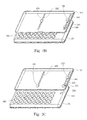
- FIG. 3 illustrates an electronic device with the dynamic sliding module according to a second preferred embodiment of the present invention.
- a wedge-shaped block 304 adjacent to the opening 232 of the first track 230 is disposed under a second shell 114 of the first electronic module 110. While the dynamic slide 164 is moved to the opening 232, the dynamic slide 164 can be pushed downwards and out of the opening 232 by the incline of the wedge-shaped block 304 so as to retract back to the surface 240 of the second electronic module 120.
- the height of the dynamic slide 164 above the track 230 can be lower than the first slide 210 such that the dynamic slide 164 is easily pushed out of the opening 232 by the wedge-shaped block 304.
- the height of the first slide 210 above the track 230 can be designed to be as low as possible to prevent the first slide 210 from touching the wedge-shaped block 304 after the dynamic slide 164 is pushed out of the opening 232 of the track 230, thereby increasing the sliding stroke of the two electronic modules and the slide-out area.
- the wedge-shaped block 304 can be designed as a stopping block for stopping the first slide 210 from moving further.
- the diameter of the dynamic slide 164 is preferably smaller than the diameter of the first slide 210 so as to prevent the first slide 210 from being disengaged from the opening 168 or the opening 232. More preferably, the diameter of the first slide 210 is larger than the diameters of the first opening 168 and the second opening 232 such that the first slide 210 can be prevented from being disengaged from the opening 168 or the opening 232 while moving along the track 230.
- the dynamic sliding module according to the present invention can effectively increase the sliding stability between two electronic modules of an electronic device such as a slide cell phone, effectively increase the usable area (i.e. the slide-out area) on the electronic device, and further increase the operating functions thereof.
Landscapes
- Engineering & Computer Science (AREA)
- Signal Processing (AREA)
- Telephone Set Structure (AREA)
- Bearings For Parts Moving Linearly (AREA)
- Casings For Electric Apparatus (AREA)
Abstract

Description
- The present invention generally relates to a dynamic sliding module for an electronic device. More particularly, this invention relates to a magnetically dynamic sliding module for an electronic device.
- Since wireless communication technology is highly developed, mobile phones are becoming increasingly light and easy to hold. Nowadays, most people use mobile phones to communicate with others. Therefore, the mobile phone has become a necessary electronic device in people's lives
- Due to the popularity of mobile phones, mobile phone manufacturers are working extremely hard to increase mobile phone functions in order to satisfy various requirements desired by users. For example, some of the mobile phones provide PDA functions, such as address book, calendar, minutes and/or agendas. Some mobile phones provide electronic games therein for the users to play during their idle time. Further, some mobile phones have digital cameras thereon so that users can take beautiful pictures to share with their friends.
- However, a current mobile phone generally has a size smaller than that of a palm, and especially, a smaller mobile phone only has a size almost similar to that of an egg. Therefore, the surface area for the keyboard and display on a mobile phone is limited. Integrating all the foregoing functions into such a small mobile phone is difficult. To increase the available surface area, some mobile phones are designed to dispose the keyboard and the display respectively on two electronic modules, which are connected to each other via a sliding mechanism, so as to construct, for example, a slide cell phone including a sliding keyboard and a sliding display.
- In order to increase the sliding stability between the sliding keyboard and the sliding display, the sliding mechanism has to occupy a predetermined length of a sliding track and thus limits the sliding length of the sliding track such that the slide-out area on the sliding keyboard is reduced. Accordingly, there is a need to reduce the waste length of the sliding track occupied by the sliding mechanism so as to increase the usable slide-out area on a slide cell phone.
- It is an objective of the present invention to provide a dynamic sliding module to increase the surface area of an electronic device.
- It is another objective of the present invention to provide a dynamic sliding module using an attracting force, such as a magnetic force, to engage a dynamic slide with a track in a part of the stroke thereof to increase the sliding stability for two electronic sliding modules of an electronic device.
- It is yet another objective of the present invention to provide a dynamic sliding module with a dynamic slide escaping from a track in a part of the stroke thereof to increase the surface area and the stroke of two electronic sliding modules of an electronic device.
- To accomplish the above objectives, the present invention provides a dynamic sliding module for coupling a first electronic module to a second electronic module of an electronic device, and increasing both the sliding reliability and the area of exposable surfaces therebetween. The electronic device is, for example, a mobile phone, such as a slider cell phone. The first electronic module is, for example, a sliding display, and the second electronic module is, for example, a sliding keyboard. The dynamic sliding module includes a track with a first opening, a dynamic slide, and a guiding device, such as an attracting device, to guide the dynamic slide into the track through the first opening while the dynamic slide is moved to be aligned with the first opening so as to enable the dynamic slide to engage with and slide on the track.
- The track further includes a second opening for withdrawing the dynamic slide from the track. The dynamic sliding module further includes an elastic device coupled to the dynamic slide to withdraw the dynamic slide from the track through the second opening and back to the second electronic module. The dynamic sliding module further includes a wedge-shaped block being disposed adjacent to the second opening and having an incline to push the dynamic slide out of the track from the second opening.
- The guiding device is preferably an attracting device. In one preferred embodiment, the dynamic slide is made of a magnetic material and the attracting device is made of a ferromagnetic material. In another preferred embodiment, the dynamic slide is made of a ferromagnetic material and the attracting device is made of a magnetic material. In a further another preferred embodiment, the dynamic slide and the magnetic device are made of a magnetic material and adjacent surfaces thereof have different polarities.
- The dynamic sliding module can further include a magnetic device disposed above the second opening, and the dynamic slide and the magnetic device are made of a magnetic material and the adjacent surfaces thereof have the same polarity.
- The dynamic sliding module can further utilize a first slide attached on the track to couple the first electronic module to the second electronic module. The diameter of the first slide is preferably larger than the diameter of the dynamic slide. More preferably, the diameter of the first slide is larger than the diameter of the first opening and/or the second opening so that the first slide can slide on the track and be prevented from escaping the track. The first slide is preferably lower than the wedge-shaped block to prevent the first slide from touching the wedge-shaped block while the dynamic slide is pushed out of the track to further increase the area of the exposable surface between the first electronic module and the second electronic module. Alternatively, the wedge-shaped block is designed to be a stopping block for stopping the first slide.
- Accordingly, the dynamic sliding module according to the present invention can increase the sliding reliability of the sliding electronic modules for the electronic device, and increase the area of the exposable surfaces for the electronic device to control the electronic device and/or increase the functionality thereof. In addition, since the dynamic slide only engages with the track in a part route of the track, the dynamic sliding module can increase the variations of the electronic device, especially for the mobile phone.
- The foregoing aspects and many of the attendant advantages of this invention will be more readily appreciated as the same becomes better understood by reference to the following detailed description, when taken in conjunction with the accompanying drawings, wherein:
- FIG. 1 illustrates a dynamic sliding module according to the present invention;
- FIGS. 2A to 2C illustrate operating status of a first preferred embodiment of an electronic device with the dynamic sliding module according to the present invention; and
- FIG. 3 illustrates a second preferred embodiment of an electronic device with the dynamic sliding module according to the present invention.
- The following description is currently the best implementation of the present invention. This description is not to be taken in a limiting sense but is made merely to describe the general principles of the invention. The scope of the invention should be determined by referencing the appended claims.
- FIG. 1 illustrates a dynamic sliding module according to the present invention. An electronic device includes a first
electronic module 110, a secondelectronic module 120, and adynamic sliding module 160. The firstelectronic module 110 and the secondelectronic module 120 are slidable relative to each other so as to expose inner surfaces of the firstelectronic module 110 and the secondelectronic module 120. - The
dynamic sliding module 160 includes a guiding device, such as an attractingdevice 162 shown in FIG. 1, adynamic slide 164, and sliding tracks (referring to FIGS. 2A to 2C). While thedynamic slide 164 disposed on the secondelectronic module 120 is aligned with the attractingdevice 162, thedynamic slide 164 is able to be attracted into the track through theopening 168 of the track so as to increase the sliding stability between the firstelectronic module 110 and the secondelectronic module 120. Thedynamic sliding module 160 further includes anelastic device 166 to assist thedynamic slide 164 in returning to the secondelectronic module 120. The electronic device is preferably a slide cell phone with the firstelectronic module 110, such as a sliding display, and the secondelectronic module 120, such as a sliding keyboard. The guiding device is not limited to the attractingdevice 162. Any force able to guide thedynamic slide 164 into the track can be used in the dynamic sliding module according to the present invention. - FIGS. 2A to 2C illustrate the operating status of an electronic device using the dynamic sliding module according to a first preferred embodiment of the present invention. For clear illustration, part of the first electronic module is removed to show a
first shell 112, and afirst slide 210, asecond slide 220, afirst track 230, asecond track 222 and adynamic slide 164 disposed therein. - The
first slide 210 and thesecond slide 220 are respectively coupled to thefirst track 230 and thesecond track 222 and able to slide thereon. While thefirst shell 112 and the secondelectronic module 120 slide relative to each other, thefirst shell 112 can slide along thefirst track 230 and thesecond track 222 with thefirst slide 210 and thesecond slide 220 sliding in thefirst track 230 and thesecond track 222 respectively. - However, if the
first slide 210 and thesecond slide 220 are too small, the sliding stability between thefirst shell 112 and the secondelectronic module 120 may be reduced. On the contrary, if thefirst slide 210 and thesecond slide 220 are too large, the sliding stroke of thefirst shell 112 and the secondelectronic module 120 may therefore be shortened so that the slide-out area, e.g. the area of thesurface 240, on the secondelectronic module 120 is reduced. - The
first track 230 has anopening 168 and anotheropening 232 such that when thedynamic slide 164 is aligned with theopening 168, thedynamic slide 164 can be attracted into thefirst track 230 through theopening 168 by an attractive force, e.g. a magnetic force, between the attractingdevice 162 and thedynamic slide 164 and thus be able to slide on thefirst track 230. When thefirst shell 112 and the secondelectronic module 120 are slid relative to each other, thefirst slide 210, thesecond slide 220 and thedynamic slide 164 slide coplanarly along thefirst track 230 and thesecond track 222 respectively thereby increasing the sliding stability between thefirst shell 112 and the secondelectronic module 120. - When the
dynamic slide 164 moves away from the attractingdevice 162 and reaches theopening 232, thedynamic slide 164 can move downwards and return to the secondelectronic module 120. Thedynamic slide 164 and the attractingdevice 162 are preferably attracted to each other with a magnetic force. For example, thedynamic slide 164 is made of a magnetic material while the attractingdevice 162 is made of a ferromagnetic material, thedynamic slide 164 is made of a ferromagnetic material while the attractingdevice 162 is made of a magnetic material, or both thedynamic slide 164 and the attractingdevice 162 are made of a magnetic material with their adjacent surfaces having different polarities. - While the
dynamic slide 164 is made of a magnetic material, a magnetic device (not shown), which is made of a magnetic material and has one surface having the same polarity as the upper surface of thedynamic slide 164, can be disposed above and have the one surface facing to theopening 232, thereby replacing or assisting theelastic device 166 to push thedynamic slide 164 back to the secondelectronic module 120 by a repulsive force formed between thedynamic slide 164 and the magnetic device. - When the
dynamic slide 164 returns back to the secondelectronic module 120 through theopening 232, the upper surface of thedynamic slide 164 is preferably lower or equal to thesurface 240 of the secondelectronic module 120 to avoid interference with the sliding of thefirst shell 112 on thesurface 240 of the secondelectronic module 120. After being withdrawn from thefirst track 230 and returning back to the secondelectronic module 120, thedynamic slide 164 does not occupy thefirst track 230 so that thefirst shell 112 can continuously slide along thefirst track 230 until thefirst slide 210 is moved to the end of thefirst track 230. - Accordingly, the dynamic sliding module according to the present invention can increase not only the sliding stability between two sliding electronic modules for an electronic device but also the slide-out area of the electronic device such that the electronic device, e.g. an slide cell phone as shown in FIGS. 2A to 2C, can provide not only a smooth sliding process but also a larger slide-out area of the
surface 240 for installing additional operation devices, such as a handwriting board, thereby effectively controlling the electronic device. - FIG. 3 illustrates an electronic device with the dynamic sliding module according to a second preferred embodiment of the present invention. Referring to the drawing, a wedge-shaped
block 304 adjacent to theopening 232 of thefirst track 230 is disposed under asecond shell 114 of the firstelectronic module 110. While thedynamic slide 164 is moved to theopening 232, thedynamic slide 164 can be pushed downwards and out of theopening 232 by the incline of the wedge-shapedblock 304 so as to retract back to thesurface 240 of the secondelectronic module 120. - The height of the
dynamic slide 164 above thetrack 230 can be lower than thefirst slide 210 such that thedynamic slide 164 is easily pushed out of theopening 232 by the wedge-shapedblock 304. Alternatively, the height of thefirst slide 210 above thetrack 230 can be designed to be as low as possible to prevent thefirst slide 210 from touching the wedge-shapedblock 304 after thedynamic slide 164 is pushed out of theopening 232 of thetrack 230, thereby increasing the sliding stroke of the two electronic modules and the slide-out area. Otherwise, the wedge-shapedblock 304 can be designed as a stopping block for stopping thefirst slide 210 from moving further. - The diameter of the
dynamic slide 164 is preferably smaller than the diameter of thefirst slide 210 so as to prevent thefirst slide 210 from being disengaged from theopening 168 or theopening 232. More preferably, the diameter of thefirst slide 210 is larger than the diameters of thefirst opening 168 and thesecond opening 232 such that thefirst slide 210 can be prevented from being disengaged from theopening 168 or theopening 232 while moving along thetrack 230. - Accordingly, the dynamic sliding module according to the present invention can effectively increase the sliding stability between two electronic modules of an electronic device such as a slide cell phone, effectively increase the usable area (i.e. the slide-out area) on the electronic device, and further increase the operating functions thereof.
- As is understood by a person skilled in the art, the foregoing preferred embodiments of the present invention are illustrative of the present invention rather than limiting of the present invention. It is intended that various modifications and similar arrangements be included within the spirit and scope of the appended claims, the scope of which should be accorded the broadest interpretation so as to encompass all such modifications and similar structures.
Claims (10)
- An electronic device having a first electronic module and a second electronic module slidable relative to the first electronic module, the electronic device comprising:a dynamic sliding module coupling the first electronic module to the second electronic module, wherein the dynamic sliding module comprises:a track with a first opening;a dynamic slide; anda guiding device for guiding the dynamic slide into the track through the first opening while the dynamic slide is moved to be aligned with the first opening.
- The electronic device of claim 1, wherein the track further comprises a second opening for withdrawing the dynamic slide from the track.
- The electronic device of claim 2, wherein the dynamic sliding module further comprises an elastic device coupled to the dynamic slide to withdraw the dynamic slide from the track through the second opening.
- The electronic device of claim 2, further comprising a wedge-shaped block being disposed adjacent to the second opening and having an incline to push the dynamic slide out of the track from the second opening.
- The electronic device of claim 2, wherein the dynamic sliding module further comprises a magnetic device disposed above the second opening wherein the dynamic slide and the magnetic device are made of a magnetic material and adjacent surfaces thereof have a same polarity.
- The electronic device of claim 1, wherein the guiding device is an attracting device.
- The electronic device of claim 6, wherein the dynamic slide is made of a magnetic material and the attracting device is made of a ferromagnetic material.
- The electronic device of claim 6, wherein the dynamic slide is made of a ferromagnetic material and the attracting device is made of a magnetic material.
- The electronic device of claim 6, wherein the dynamic slide and the attracting device are made of a magnetic material and adjacent surfaces thereof have different polarities.
- The electronic device of claim 1, further comprising a first slide sliding on the track and coupling the first electronic module to the second electronic module wherein the first slide has a diameter larger than a diameter of the first opening.
Applications Claiming Priority (1)
| Application Number | Priority Date | Filing Date | Title |
|---|---|---|---|
| CNB2006100023282A CN100493106C (en) | 2006-01-26 | 2006-01-26 | Dynamic sliding module and its application |
Publications (3)
| Publication Number | Publication Date |
|---|---|
| EP1814286A2 true EP1814286A2 (en) | 2007-08-01 |
| EP1814286A3 EP1814286A3 (en) | 2009-03-11 |
| EP1814286B1 EP1814286B1 (en) | 2010-05-19 |
Family
ID=37872234
Family Applications (1)
| Application Number | Title | Priority Date | Filing Date |
|---|---|---|---|
| EP20070100023 Ceased EP1814286B1 (en) | 2006-01-26 | 2007-01-02 | Dynamic sliding module and uses thereof |
Country Status (3)
| Country | Link |
|---|---|
| EP (1) | EP1814286B1 (en) |
| CN (1) | CN100493106C (en) |
| DE (1) | DE602007006561D1 (en) |
Cited By (2)
| Publication number | Priority date | Publication date | Assignee | Title |
|---|---|---|---|---|
| US20090082074A1 (en) * | 2007-09-20 | 2009-03-26 | Yi-An Chen | Electronic device and sliding cover structure |
| CN108881552A (en) * | 2018-07-09 | 2018-11-23 | Oppo广东移动通信有限公司 | A kind of electronic equipment |
Citations (3)
| Publication number | Priority date | Publication date | Assignee | Title |
|---|---|---|---|---|
| EP1220517A1 (en) * | 2000-12-28 | 2002-07-03 | Koninklijke Philips Electronics N.V. | Electronic device comprising two movable parts in relation to each other |
| US20040137940A1 (en) * | 2003-01-08 | 2004-07-15 | Sanyo Electric Co., Ltd. | Portable wireless terminal device |
| KR20060086524A (en) * | 2005-01-26 | 2006-08-01 | 엘지전자 주식회사 | Opening and shutting apparatus of slide phone |
-
2006
- 2006-01-26 CN CNB2006100023282A patent/CN100493106C/en not_active Expired - Fee Related
-
2007
- 2007-01-02 DE DE200760006561 patent/DE602007006561D1/en active Active
- 2007-01-02 EP EP20070100023 patent/EP1814286B1/en not_active Ceased
Patent Citations (3)
| Publication number | Priority date | Publication date | Assignee | Title |
|---|---|---|---|---|
| EP1220517A1 (en) * | 2000-12-28 | 2002-07-03 | Koninklijke Philips Electronics N.V. | Electronic device comprising two movable parts in relation to each other |
| US20040137940A1 (en) * | 2003-01-08 | 2004-07-15 | Sanyo Electric Co., Ltd. | Portable wireless terminal device |
| KR20060086524A (en) * | 2005-01-26 | 2006-08-01 | 엘지전자 주식회사 | Opening and shutting apparatus of slide phone |
Cited By (3)
| Publication number | Priority date | Publication date | Assignee | Title |
|---|---|---|---|---|
| US20090082074A1 (en) * | 2007-09-20 | 2009-03-26 | Yi-An Chen | Electronic device and sliding cover structure |
| CN108881552A (en) * | 2018-07-09 | 2018-11-23 | Oppo广东移动通信有限公司 | A kind of electronic equipment |
| CN108881552B (en) * | 2018-07-09 | 2021-03-05 | Oppo广东移动通信有限公司 | Electronic equipment |
Also Published As
| Publication number | Publication date |
|---|---|
| DE602007006561D1 (en) | 2010-07-01 |
| EP1814286A3 (en) | 2009-03-11 |
| CN100493106C (en) | 2009-05-27 |
| CN101009717A (en) | 2007-08-01 |
| EP1814286B1 (en) | 2010-05-19 |
Similar Documents
| Publication | Publication Date | Title |
|---|---|---|
| US7426115B2 (en) | Dynamic sliding module and uses thereof | |
| US7539011B2 (en) | Multi-directional sliding module and application thereof | |
| EP1821500A2 (en) | Multi-directional sliding module and application thereof | |
| US20080151510A1 (en) | Sliding structure for electronic device | |
| US20070091582A1 (en) | Cover-slidable mobile phone | |
| US20020190823A1 (en) | Frictionless pen ejector mechanism | |
| EP3327543A1 (en) | Soft display device for portable terminal | |
| US20100304803A1 (en) | Portable Electronic Device | |
| TW201407315A (en) | Portable electronic device | |
| US20110038105A1 (en) | Locking mechanism and electronic device | |
| CN101667081A (en) | User interface method | |
| CN208956096U (en) | Mobile terminal | |
| CN110650223B (en) | Telescopic mechanism, camera device and terminal | |
| EP1814286A2 (en) | Dynamic sliding module and uses thereof | |
| CN1956464A (en) | Sliding cover type mobile phone | |
| CN204856312U (en) | Modularization electron device | |
| CN201181454Y (en) | Touch pen ejection device and touch pen | |
| CN101155203B (en) | Semi-automatic sliding device for a portable terminal and portable terminal having the same | |
| TWM243862U (en) | Mobile phone and battery releasing-device thereof | |
| US20110053662A1 (en) | Handheld electronic device | |
| CN201174102Y (en) | Telescopic pen and combination construction thereof | |
| CN214098274U (en) | Electronic device | |
| CN207782891U (en) | Mobile terminal | |
| KR20120000123U (en) | Sliding apparatus for exterior case having battery pack | |
| CN203164573U (en) | Magnetic pole-driving zoom lens, image capture module group thereof and mobile communication apparatus |
Legal Events
| Date | Code | Title | Description |
|---|---|---|---|
| PUAI | Public reference made under article 153(3) epc to a published international application that has entered the european phase |
Free format text: ORIGINAL CODE: 0009012 |
|
| AK | Designated contracting states |
Kind code of ref document: A2 Designated state(s): AT BE BG CH CY CZ DE DK EE ES FI FR GB GR HU IE IS IT LI LT LU LV MC NL PL PT RO SE SI SK TR |
|
| AX | Request for extension of the european patent |
Extension state: AL BA HR MK YU |
|
| 17P | Request for examination filed |
Effective date: 20081114 |
|
| PUAL | Search report despatched |
Free format text: ORIGINAL CODE: 0009013 |
|
| AK | Designated contracting states |
Kind code of ref document: A3 Designated state(s): AT BE BG CH CY CZ DE DK EE ES FI FR GB GR HU IE IS IT LI LT LU LV MC NL PL PT RO SE SI SK TR |
|
| AX | Request for extension of the european patent |
Extension state: AL BA HR MK RS |
|
| GRAP | Despatch of communication of intention to grant a patent |
Free format text: ORIGINAL CODE: EPIDOSNIGR1 |
|
| AKX | Designation fees paid |
Designated state(s): DE FR GB NL |
|
| GRAS | Grant fee paid |
Free format text: ORIGINAL CODE: EPIDOSNIGR3 |
|
| GRAA | (expected) grant |
Free format text: ORIGINAL CODE: 0009210 |
|
| RAP1 | Party data changed (applicant data changed or rights of an application transferred) |
Owner name: HTC CORPORATION |
|
| AK | Designated contracting states |
Kind code of ref document: B1 Designated state(s): DE FR GB NL |
|
| REG | Reference to a national code |
Ref country code: GB Ref legal event code: FG4D |
|
| REF | Corresponds to: |
Ref document number: 602007006561 Country of ref document: DE Date of ref document: 20100701 Kind code of ref document: P |
|
| REG | Reference to a national code |
Ref country code: NL Ref legal event code: T3 |
|
| PLBE | No opposition filed within time limit |
Free format text: ORIGINAL CODE: 0009261 |
|
| STAA | Information on the status of an ep patent application or granted ep patent |
Free format text: STATUS: NO OPPOSITION FILED WITHIN TIME LIMIT |
|
| 26N | No opposition filed |
Effective date: 20110222 |
|
| REG | Reference to a national code |
Ref country code: DE Ref legal event code: R097 Ref document number: 602007006561 Country of ref document: DE Effective date: 20110221 |
|
| REG | Reference to a national code |
Ref country code: FR Ref legal event code: PLFP Year of fee payment: 10 |
|
| REG | Reference to a national code |
Ref country code: FR Ref legal event code: PLFP Year of fee payment: 11 |
|
| REG | Reference to a national code |
Ref country code: FR Ref legal event code: PLFP Year of fee payment: 12 |
|
| PGFP | Annual fee paid to national office [announced via postgrant information from national office to epo] |
Ref country code: NL Payment date: 20181213 Year of fee payment: 13 |
|
| PGFP | Annual fee paid to national office [announced via postgrant information from national office to epo] |
Ref country code: FR Payment date: 20181213 Year of fee payment: 13 |
|
| PGFP | Annual fee paid to national office [announced via postgrant information from national office to epo] |
Ref country code: DE Payment date: 20181218 Year of fee payment: 13 Ref country code: GB Payment date: 20190102 Year of fee payment: 13 |
|
| REG | Reference to a national code |
Ref country code: DE Ref legal event code: R119 Ref document number: 602007006561 Country of ref document: DE |
|
| REG | Reference to a national code |
Ref country code: NL Ref legal event code: MM Effective date: 20200201 |
|
| GBPC | Gb: european patent ceased through non-payment of renewal fee |
Effective date: 20200102 |
|
| PG25 | Lapsed in a contracting state [announced via postgrant information from national office to epo] |
Ref country code: FR Free format text: LAPSE BECAUSE OF NON-PAYMENT OF DUE FEES Effective date: 20200131 Ref country code: NL Free format text: LAPSE BECAUSE OF NON-PAYMENT OF DUE FEES Effective date: 20200201 Ref country code: DE Free format text: LAPSE BECAUSE OF NON-PAYMENT OF DUE FEES Effective date: 20200801 Ref country code: GB Free format text: LAPSE BECAUSE OF NON-PAYMENT OF DUE FEES Effective date: 20200102 |