EP1813796A2 - Contrôleur et procédé de contrôle pour une unité de contrôle de moteur - Google Patents
Contrôleur et procédé de contrôle pour une unité de contrôle de moteur Download PDFInfo
- Publication number
- EP1813796A2 EP1813796A2 EP07250165A EP07250165A EP1813796A2 EP 1813796 A2 EP1813796 A2 EP 1813796A2 EP 07250165 A EP07250165 A EP 07250165A EP 07250165 A EP07250165 A EP 07250165A EP 1813796 A2 EP1813796 A2 EP 1813796A2
- Authority
- EP
- European Patent Office
- Prior art keywords
- drive pulse
- injector
- control valve
- engine
- controller
- Prior art date
- Legal status (The legal status is an assumption and is not a legal conclusion. Google has not performed a legal analysis and makes no representation as to the accuracy of the status listed.)
- Withdrawn
Links
Images


Classifications
-
- F—MECHANICAL ENGINEERING; LIGHTING; HEATING; WEAPONS; BLASTING
- F02—COMBUSTION ENGINES; HOT-GAS OR COMBUSTION-PRODUCT ENGINE PLANTS
- F02D—CONTROLLING COMBUSTION ENGINES
- F02D41/00—Electrical control of supply of combustible mixture or its constituents
- F02D41/20—Output circuits, e.g. for controlling currents in command coils
-
- F—MECHANICAL ENGINEERING; LIGHTING; HEATING; WEAPONS; BLASTING
- F02—COMBUSTION ENGINES; HOT-GAS OR COMBUSTION-PRODUCT ENGINE PLANTS
- F02D—CONTROLLING COMBUSTION ENGINES
- F02D41/00—Electrical control of supply of combustible mixture or its constituents
- F02D41/24—Electrical control of supply of combustible mixture or its constituents characterised by the use of digital means
- F02D41/2406—Electrical control of supply of combustible mixture or its constituents characterised by the use of digital means using essentially read only memories
- F02D41/2425—Particular ways of programming the data
- F02D41/2429—Methods of calibrating or learning
- F02D41/2438—Active learning methods
-
- F—MECHANICAL ENGINEERING; LIGHTING; HEATING; WEAPONS; BLASTING
- F02—COMBUSTION ENGINES; HOT-GAS OR COMBUSTION-PRODUCT ENGINE PLANTS
- F02D—CONTROLLING COMBUSTION ENGINES
- F02D41/00—Electrical control of supply of combustible mixture or its constituents
- F02D41/24—Electrical control of supply of combustible mixture or its constituents characterised by the use of digital means
- F02D41/2406—Electrical control of supply of combustible mixture or its constituents characterised by the use of digital means using essentially read only memories
- F02D41/2425—Particular ways of programming the data
- F02D41/2429—Methods of calibrating or learning
- F02D41/2451—Methods of calibrating or learning characterised by what is learned or calibrated
- F02D41/2464—Characteristics of actuators
- F02D41/2467—Characteristics of actuators for injectors
- F02D41/247—Behaviour for small quantities
-
- F—MECHANICAL ENGINEERING; LIGHTING; HEATING; WEAPONS; BLASTING
- F02—COMBUSTION ENGINES; HOT-GAS OR COMBUSTION-PRODUCT ENGINE PLANTS
- F02D—CONTROLLING COMBUSTION ENGINES
- F02D41/00—Electrical control of supply of combustible mixture or its constituents
- F02D41/30—Controlling fuel injection
- F02D41/38—Controlling fuel injection of the high pressure type
- F02D41/3809—Common rail control systems
- F02D41/3836—Controlling the fuel pressure
-
- F—MECHANICAL ENGINEERING; LIGHTING; HEATING; WEAPONS; BLASTING
- F02—COMBUSTION ENGINES; HOT-GAS OR COMBUSTION-PRODUCT ENGINE PLANTS
- F02D—CONTROLLING COMBUSTION ENGINES
- F02D41/00—Electrical control of supply of combustible mixture or its constituents
- F02D41/30—Controlling fuel injection
- F02D41/38—Controlling fuel injection of the high pressure type
- F02D41/40—Controlling fuel injection of the high pressure type with means for controlling injection timing or duration
-
- F—MECHANICAL ENGINEERING; LIGHTING; HEATING; WEAPONS; BLASTING
- F02—COMBUSTION ENGINES; HOT-GAS OR COMBUSTION-PRODUCT ENGINE PLANTS
- F02D—CONTROLLING COMBUSTION ENGINES
- F02D41/00—Electrical control of supply of combustible mixture or its constituents
- F02D41/02—Circuit arrangements for generating control signals
- F02D41/04—Introducing corrections for particular operating conditions
- F02D41/08—Introducing corrections for particular operating conditions for idling
-
- F—MECHANICAL ENGINEERING; LIGHTING; HEATING; WEAPONS; BLASTING
- F02—COMBUSTION ENGINES; HOT-GAS OR COMBUSTION-PRODUCT ENGINE PLANTS
- F02M—SUPPLYING COMBUSTION ENGINES IN GENERAL WITH COMBUSTIBLE MIXTURES OR CONSTITUENTS THEREOF
- F02M57/00—Fuel-injectors combined or associated with other devices
- F02M57/02—Injectors structurally combined with fuel-injection pumps
-
- Y—GENERAL TAGGING OF NEW TECHNOLOGICAL DEVELOPMENTS; GENERAL TAGGING OF CROSS-SECTIONAL TECHNOLOGIES SPANNING OVER SEVERAL SECTIONS OF THE IPC; TECHNICAL SUBJECTS COVERED BY FORMER USPC CROSS-REFERENCE ART COLLECTIONS [XRACs] AND DIGESTS
- Y02—TECHNOLOGIES OR APPLICATIONS FOR MITIGATION OR ADAPTATION AGAINST CLIMATE CHANGE
- Y02T—CLIMATE CHANGE MITIGATION TECHNOLOGIES RELATED TO TRANSPORTATION
- Y02T10/00—Road transport of goods or passengers
- Y02T10/10—Internal combustion engine [ICE] based vehicles
- Y02T10/40—Engine management systems
Definitions
- the present invention relates to the field of engine management and in particular relates to a method of and equipment for determining operating parameters of a fuel injected internal combustion engine and to engine control in dependence thereon.
- the invention additionally relates to a carrier medium carrying computer readable code for controlling a processor or computer to carry out said control method.
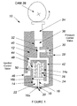
- a known fuel injector 10 for use in a fuel injected engine is shown schematically in Figure 1.
- the fuel injector 10 includes a nozzle body 12 provided with a blind bore 14 within which a valve needle 16 is slidable.
- the lower end 16a of the needle 16 is shaped to be engageable with a valve seating 18 defined by the end of the bore 14 to control fuel delivery through one or more outlet openings 20 provided in the nozzle body 12.
- a delivery chamber 22 is defined by the needle 16 and bore 14 and engagement of the valve needle 16 prevents fuel within the delivery chamber 22 flowing past the seating 18 and out through the outlet openings 20 into the associated engine cylinder or other combustion space.
- the valve needle 16 is provided with a plug member 16b having a cross section equal to that of the bore 14.
- the lower surface of the member 16b defines a thrust surface such that fuel pressure within the delivery chamber 22 acts on the thrust surface to urge the needle 16 away from its seating 18.
- the upper region 14a of the bore 14 defines, along with the upper surface of the member 16b, a control chamber 24 for fuel.
- a spring 26 located within the control chamber 24 acts on the upper end of the bore 14 and the upper surface of the member 16b to urge the valve needle 16 onto its seating 18.
- Fuel is supplied to the injector from a source of pressurised fuel, for example from a low pressure source or from the common rail of a common rail fuel system.
- a source of pressurised fuel for example from a low pressure source or from the common rail of a common rail fuel system.
- fuel is supplied through an inlet region 28 which houses a pressure control valve 30.
- the pressure control valve 30 may be opened and closed to respectively allow and block the supply of fuel into and out of the injector 10.
- the injector body 12 is provided with a further bore 32 within which a plunger 34 is slidable.
- the plunger 34 and bore 32 define a pump chamber 36.
- the plunger 34 is associated with a cam arrangement 38 such that rotation of the cam arrangement 38 causes the plunger 34 to slide within the bore 32.
- the inlet region 28 is connected, when the pressure control valve 30 is open, to the pump chamber 36 by means of a supply passage 40.
- the supply passage branches 40 into two further supply passages 42, 44.
- Passage 42 connects the inlet region 28 and pump chamber 36 to the delivery chamber 22.
- Passage 44 connects to an outlet region 46 which is in communication with a fuel drain (not shown).
- Passage 44 is connected via a restricted passage 48 to the control chamber 24.
- a needle control valve 50 is housed within the passage 44 and is operable to move from a first position in which the control chamber 24 is in communication with the pump chamber 36 and inlet region 28 and the outlet region 46 is blocked and a second position in which the flow of fuel from the pump chamber 36 or inlet region 28 to the control chamber 24 is blocked and the outlet region 46 is in communication with the control chamber 24 thereby allowing pressurised fuel within the control chamber 24 to dump to the fuel drain.
- pressure control valve 30 and needle control valve 50 will typically be pressure balanced valves in order to make valve operation at high pressures easier.
- Injectors used in fuel injection systems are generally controlled electrically by means of a current or voltage waveform applied to the injector.
- the properties or shape of the waveform applied to the injectors determines the type of injection performed by the injectors. For example, a first waveform may be arranged to cause the injector to generate a pilot injection followed by a single main injection while a second waveform may be arranged to generate a single main injection with no preceding pilot injection.
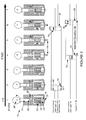
- the Figure additionally shows the pressure control valve control logic structure 60, the motion of the pressure control valve 62, the needle control valve logic structure 64 and the position 66 of the needle 16 over time.
- the needle control valve logic structure 64 defines when fuel is injected and the pressure control valve logic structure 60 details when the pressure control valve is opened and closed (which therefore affects the pressure within the system).
- the logic structures define the shape of the current waveforms of the control signals that are sent from an engine control unit (not shown in Figure 2) to the injectors of the engine.
- the needle control valve 50 is closed such that fuel cannot flow to the fuel drain.
- the pressure control valve 30 is open and low pressure fuel flows into the injector 10 and therefore into the pump chamber 36, control chamber 24 and delivery chamber 22.
- the needle 16 is engaged with its seating 18 such that fuel is unable to pass through the outlet opening 20 into the combustion chamber.
- valve 62 and needle position 66 are also depicted for position 1.
- valve 30 does not move at exactly the same time as the logic structure 60 changes. However, after a short time delay ( ⁇ T1) the valve 30 moves from open to closed as represented by the step down 70 in the pressure control valve motion line 62.
- cam arrangement 38 has rotated slightly compared to its position in state 1 and that therefore the plunger 34 has moved down into the bore 32 slightly.
- the needle control valve 50 When the pressure within the injector 10 has risen to a sufficient level the needle control valve 50 is opened (as represented by the step up 72 in the logic structure 64 for the needle valve 50). Fuel within the control chamber 24 which is under pressure flows past the needle control valve 50 and out the outlet region 46 to the fuel drain. The pressure within the control chamber 24 therefore falls and the pressure of fuel acting on the lower surface of the member 16b is sufficient to overcome the action of the spring 26 and to lift the needle 16 from its seating 18. Fuel is then injected 74 from the injector 10 into the combustion chamber.
- the needle lift is shown as the step up 76 on the line 66. Again, it is noted that there is a delay ( ⁇ T2) between the change in the needle control logic structure 64 and the needle lift 76.
- the logic structure 60 of the pressure control valve 30 changes again in order to open the pressure control valve 30 again.
- the logic structure 60 correspondingly shows a step down 78.
- ⁇ T3 After a short delay ( ⁇ T3) again the valve 30 moves from closed to open (step up 80 in motion line 62).
- state 6 the needle control valve 50 is closed again (as represented by the change 82 in the logic structure 64). After a short delay ( ⁇ T4) the needle 12 moves back (step down 84) to its seating 18 and the injection of fuel into the combustion chamber ends.
- State 7 equates, in part, to state 1 and the progression shown from state 1 to state 7 represents one injection cycle, though it does not include the filling part of the cycle which occurs over part of the rest of the rotation of the cam.
- Injection duration 86 is indicated as the time between the needle lifting 76 from its seating and then returning 84 once again to its seating.
- the injection equipment will experience wear and tear during the lifetime use of the system. This results in the degradation of the fuel injection equipment and overall engine performance in terms of emissions and power.
- GB-A-2305727 describes an arrangement in which a sound sensor is mounted upon or associated with an engine. The output of the sensor is filtered and used to monitor movement of an injector needle and to monitor combustion. A method is described whereby the minimum drive pulse length which must be applied to an injector to cause the injector to open can be derived.
- US 6082326 A further method for counteracting the effect of wear and tear within the system is disclosed in US 6082326 .
- An accelerometer is mounted on the engine and listens for each injection event. This allows the engine management system to match injection pulse durations to the characteristics of each individual injector and to establish the minimum drive pulse required for each injector. This provides consistently better fuel economy and emission performance by reducing fuel volume tolerances.
- the above methods and devices require the provision of additional sensors within the engine system and suitable signal analysis means to analyse the detected signals and determine the various injector events occurring across the engine.
- the present invention seeks to overcome or substantially mitigate the above mentioned problems and to provide a method and apparatus for determining minimum drive pulses for the injectors of a fuel injected engine without the need for additional sensors and associated signal processing means.
- a first aspect of the present invention provides a controller for determining drive pulse structures for controlling the operation of control valves of a fuel-injected engine, the engine comprising a first injector and at least one further injector, and the controller comprising: inputs for receiving engine data relating to an engine system parameter, outputs for outputting a control function for controlling the injector valves of the first injector; the control function being derived from a control valve drive pulse structure; a processor for controlling the control function output from the controller wherein the processor is arranged to (i) progressively modify the control valve drive pulse structures, (ii) to detect injection events within the first injector by measuring changes in the engine data and (iii) to thereby determine the minimum width of the drive pulse structures that permit injection to take place.
- the present invention recognises that the provision of separate vibration sensors or accelerometers to determine pulse structures of injectors within an engine is not necessary.
- the invention recognises that varying the pulse structures of an injector under test will have the effect that one or more engine system parameters will vary.
- the invention may monitor a number of engine system parameters. For example, fuel value data relating to the quantity of fuel injected per injection cycle per injector for the at least one injector may be monitored. Alternatively, the rotation of the engine's crank wheel may be tracked by monitoring the times between successive crank teeth on the flywheel.
- the present invention allows the detection of engine injection events by measuring changes in the monitored engine system parameters. It is noted that the controller of the present invention may monitor one or more of the above parameters at any given time.
- the present invention may be applied to a fuel injection system in which the injectors have pressure control and needle control valves (as shown, for example in Figure 1).
- the invention can equally be applied however in whole or in part to single valve components operating using a mechanical injector, as well as other two valve systems, for example where the pump and injector are separate items, e.g. unit pump-pipe-injector arrangements.
- the injector comprises a pressure control valve and a needle control valve.
- the processor within the controller determines the minimum drive pulse structure for the pressure control valve first.
- the controller may then subsequently determine the minimum drive pulse structure for the needle control valve.
- the engine system parameter monitored by the controller is fuel value data.
- the fuel used by an engine per complete injection cycle i.e. the fuel used during a cycle in which all the cylinders normally fire
- the term "fuel value” refers to the quantity of fuel that is injected per injection cycle per (injector) cylinder of the engine. If the drive pulse structures of a first injector within the engine are modified sufficiently, that injector will cease injecting fuel into its associated cylinder. Since the total amount of fuel injected into the engine at any time will be maintained by the action of the engine management system, the removal of one injector from operation means that the fuel quantity per cylinder passing through the remaining injectors (the fuel value) will increase. Conversely, if the injector re-commences injection the fuel quantities per cylinder passing through the remaining injectors will decrease (relative to the increased level).
- the present invention utilises the changing fuel values at the remaining injectors within the engine to determine whether injection is taking place at the injector under test.
- By appropriately varying the drive pulse structures applied to the control valve(s) of the first injector and measuring the fuel value at other injectors it is possible to determine the minimum drive pulses that will result in a control function that will cause injection to occur.
- the quantity of fuel required to maintain a certain engine speed is, at some point, converted to a cranking angle via a process called linearization.
- linearization As the engine experiences general usage and wear and tear a time varying offset will be introduced into the relationship between fuel quantity and crank angle.
- the individual characteristics of each individual injector i.e. the minimum drive pulse of each injector
- the present invention allows the engine system to be periodically re-calibrated by calculating the minimum drive pulses that need to be applied to the various control valves within the fuel injected engine.
- the engine is governed to a substantially constant engine speed, for example the engine is idling.
- the state of the engine should be stable such that engine speed and fuel value are relatively constant over time.
- the minimum drive pulse for the pressure control valve may be determined as follows. Starting with an injector that is injecting fuel, the processor is arranged to firstly reduce the pulse widths for all the control valves within the injector under test such that injection stops. The processor then progressively increases the pulse widths for the control valves until injection is detected. The injection event can be determined by the change in fuel value that occurs when injection re-commences through the injector. The drive pulse width for the pressure control valve at the point that injection re-commences can be set as the minimum drive pulse for the pressure control valve. It is noted that during the determination of the minimum drive pulse for the pressure control valve, the needle control valve is left open. This is to ensure that the controller is only effectively measuring the logic pulse length required to generate sufficient pressure in the delivery chamber of the injector that is required to overcome the pre-loading of the spring that holds the needle against its seating.
- the processor can determine the minimum drive pulse for the needle control valve. In order to do this the processor sets and holds the drive pulse for the pressure control valve at the recently determined minimum value. The start time of the drive pulse for the needle control valve can then be progressively moved later such that the width of the drive pulse for the needle control valve is progressively decreased until injection stops from the injector. The width of the drive pulse just before injection stops can be set as the minimum drive pulse for the needle control valve.
- the engine system parameter monitored by the controller is data related to the rotation of a crank wheel, e.g. the speed of rotation of the crank or the crank tooth time.
- crank wheel (or flywheel) is part of the crankshaft assembly within the engine system that converts the linear motion of the pistons into rotational motion that is transmitted to the load.
- a typical crank wheel comprises a number of slots or teeth machined at regular intervals around its periphery.
- a sensor for example a variable reluctance sensor, can be used to detect the motion of the crank teeth and therefore provide position information that can be used for engine speed measurement and fuel pulse scheduling.
- crank tooth time refers to the time between successive crank teeth on the flywheel.
- the present invention recognises that as the control valve pulse structure for the injector under test is varied the crank speed of the crank wheel will vary. Monitoring changes in the crank speed can therefore provide a means for determining engine injection events such that the minimum width of the drive pulse structure for the test injector can be determined.
- the controller receives data relating to the rotation of the crank wheel.
- the processor can monitor the speed of the crank wheel across engine injection cycles.
- the processor can monitor crank tooth times across the engine injection cycle.
- a typical crank wheel will comprise a number of teeth which are associated with the action of one of the injectors within the engine system.
- the processor monitors the crank wheel speed with respect to tooth number for the injector under test and then subtracts these speed values from one of the other injectors within the engine in order to derive a relative crank wheel speed with respect to tooth number. Changes in the derived relative crank wheel speed can indicate when an injection event has occurred.
- crank wheel speed can be monitored for a particular crank tooth or combination of teeth as the control valve pulse drive structure is varied for the injector under test. Changes in the relative crank wheel speed for a particular crank tooth or combination thereof can therefore indicate that an injection event has occurred.
- the minimum drive pulse for the pressure control valve may be determined as follows. Starting with an injector that is injecting fuel, the processor is arranged to firstly reduce the pulse widths for all the control valves within the injector under test such that injection stops. The processor then progressively increases the pulse widths for the control valves until injection is detected.
- the injection event can be determined by changes in the measured crank wheel speed or in the crank tooth times at given points in the injection cycle that occur when injection re-commences through the injector.
- the drive pulse width for the pressure control valve at the point that injection re-commences can be set as the minimum drive pulse for the pressure control valve. It is noted that during the determination of the minimum drive pulse for the pressure control valve, the needle control valve is left open. This is to ensure that the controller is only effectively measuring the logic pulse length required to generate sufficient pressure in the delivery chamber of the injector that is required to overcome the pre-loading of the spring that holds the needle against its seating.
- the processor can determine the minimum drive pulse for the needle control valve. In order to do this the processor sets and holds the drive pulse for the pressure control valve at the recently determined minimum value. The start time of the drive pulse for the needle control valve can then be progressively moved later such that the width of the drive pulse for the needle control valve is progressively decreased until injection stops from the injector. The width of the drive pulse just before injection stops can be set as the minimum drive pulse for the needle control valve.
- the processor progressively varies the drive pulses for the control valves by performing a number of iterations with different drive pulses as appropriate in each iteration.
- a method for determining drive pulse structures for controlling the operation of control valves of a fuel-injected engine comprising a first injector and at least one further injector, and the method comprising: receiving engine data relating to an engine system parameter; outputting a control function for controlling the injector valves of the first injector, the control function being derived from a control valve drive pulse structure; controlling the control function output from the controller by (i) progressively modifying the control valve drive pulse structures, (ii) detecting injection events within the first injector by measuring changes in the engine data and (iii) determining the minimum width of the drive pulse structures that permit injection to take place.
- a carrier medium for carrying a computer readable code for controlling a processor, computer or other controller to carry out the method of the first aspect of the invention.
- the invention extends to a vehicle comprising a controller according to the first aspect of the present invention and also to a diagnostic unit for use with a vehicle, the unit comprising a controller according to the first aspect of the present invention.
- fuel value is used to define the quantity of fuel that is injected per injection cycle per cylinder of the engine.
- quantity of fuel is traditionally measured in milligrams.
- minimum drive pulse or “MDP” is used to define the length of a control feature in the logic structure of either the pressure control or needle control valves that results in injection of fuel into the combustion chamber of the engine.
- the controller will be trying to ensure the total fuel injected by all the injectors within an engine remains constant.
- the controller's fuel value under such cases will be related to the total net fuel injected into the engine per injection cycle divided by the total number of injectors. If an injector fails to inject fuel then the controller will attempt to correct for this by increasing the fuel value, with the result that the fuel injected through each of the remaining (operating) injectors will increase until the total fuel injected through all injectors is once again close to the previous level. So, for a six cylinder engine idling with about 15mg per injector of fuel being injected, there will be a fuel value close to 15mg.
- the present invention recognises that changes in the logic structure of the injector valves can be derived by detecting changes in the fuel value.
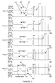
- Figure 3 shows the test procedure according to a first embodiment of the present invention for determining the minimum drive pulse of the pressure control valve logic pulses that will generate a control waveform that will cause fuel injection into the combustion chamber.
- the Figure shows the pressure control valve control logic structure 100, the motion of the pressure control valve 102, the needle control valve control logic structure 104 and the position 106 of the needle 12 over time.
- the needle control valve structure 104 defines when fuel is injected and the pressure control valve logic structure 100 details when the pressure valve is opened and closed (which therefore affects the pressure within the system).
- the pulse widths in the logic structure are set to a short enough value such that injection does not occur into the cylinder associated with that injector.
- the fuel value across the remaining injectors within the engine is allowed to stabilise and then the following procedure is initiated.
- the pressure control valve is initially open.
- Logic pulses (107, 108) for the pressure control and needle control valves are shown in which the pulses commence at the same point 110 in time.
- the closing of the pressure control valve is depicted by the trough 112 in the pressure control valve motion line 102. It can be seen that this logic structure (100, 104) does not result in any needle lift (the needle lift trace 106 is a flat line).
- the lack of needle lift is confirmed by the unchanging fuel value 114 (see fuel value versus iteration graph for Iteration 1).
- the drive pulse 106 in the pressure control logic structure has been lengthened 116d sufficiently that injection of fuel takes place.
- the injection of fuel is indicated by the falling fuel value 120 (since there is now an extra injector that is injecting fuel the total fuel load is spread over an extra injector and consequently the amount of fuel delivered via each of the other injectors is reduced compared to Iteration 4) and is also shown by the spike 122 in the needle lift line 106.
- the lengthening of the needle control pulse is shown by 118d.
- the length of the pressure control drive pulse in Iteration 5 corresponds to the minimum drive pulse (MDP) 124 for the pressure control valve for this particular injector that is required to enable injection to take place.
- MDP minimum drive pulse
- the object of the needle control valve test is to reduce the length 126 of the drive pulse 108 of the needle valve until injection from the injector ceases. During this part of the test the pressure control valve drive pulse is held at the recently determined minimum value 124.
- the logic structures (100, 104) of the pressure control and needle control valves are such that injection is taking place from the injector.
- the object of this part of the test procedure is therefore to reduce the drive pulse 108 for the needle control valve until such time as injection stops.
- the length of the drive pulse immediately before this happens will then be the minimum drive pulse that can be used with the needle control valve at this test condition.
- the loss of injection will be accompanied with an increase in the detected fuel value 114 (as the total fuel load is spread over a reduced number of injectors).
- the drive pulse length in Iteration 4 can then be set as the minimum drive pulse 134 for the needle control valve that will still allow injection to take place.
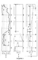
- FIG. 5 shows the various parameters that the control device monitors and controls in the performing the above test procedures.
- the top graph 140 shows the measured fuel value 114 over time.
- the middle graph 142 shows the width of the pressure control valve drive pulse 107 over time and the bottom graph 144 shows the width of the needle control valve drive pulse 108 over time.
- the engine is governed to a "constant" engine speed, for example idling.
- the state of the engine should be stable such that engine speed and fuel value are relatively constant over time.
- the widths of the pressure and needle control valve pulses 107, 108 are set to a sufficiently low level that no injection occurs from that injector. This is shown by the falling pressure control width line 146 in the middle figure.
- the fuel value is then allowed to stabilise 150 for a period at the new, heightened fuel value. It can be seen from Figure 5 that between roughly time units 700 to 1000 the fuel value is allowed to stabilise.
- the pressure control valve drive pulse is then progressively increased (see section 152 of the middle graph 142). At the same time the needle control valve pulse is also progressively increased (see section 154 of the bottom graph 144).
- the pressure control valve drive pulse is then held at the minimum value. This is indicated by the straight line section 158 on the pressure control graph 142 that runs from time unit 2000 onwards.
- the fuel value is again allowed to stabilise before the needle control valve drive pulse is progressively decreased (see section 160 on the bottom graph 144) until injection is lost again. It is noted that the straight line 159 between time unit 1900 and 2250 on the bottom graph represents the period during which the fuel value is allowed to stabilise.
- the minimum drive pulse for the needle control valve can be defined. (In the example shown in Figure 5 the needle control valve minimum drive pulse is shown as approximately having a width of 1 unit.)
- Figures 6 to 10 either relate to or are useful for understanding a second embodiment of the present invention.
- Figure 6 illustrates a typical flywheel 200. It can be seen that the flywheel comprises a number of teeth 201 on its outer periphery which are arranged into three groups (202, 204, 206). Each group (202, 204, 206) is associated with an injector (injector X, injector X+1 and injector X+2) and each group comprises 18 teeth which are regularly spaced at 6-degree intervals. The group of teeth for injector X are partially numbered (teeth 1, 11 and 18 are numbered).
- Three regions (208, 210, 212) on the flywheel are not machined, ie have no teeth..
- a sensor 214 for example, a variable reluctance sensor, is shown opposite tooth 11 in group 202. This sensor is used to detect motion of the crank teeth 201 and the decoded signal output from the sensor is used to provide position information which is used for engine speed measurement and fuel pulse scheduling. It is noted that any suitable sensor may be used to measure crank tooth motion, e.g. an optical based sensor may be used.
- crank tooth time is the time between successive crank teeth. This is illustrated in Figure 7 which shows the decoded signal output from the sensor of Figure 6.
- Figure 8 shows an example for crank tooth times and crank speeds for a test injector X and a subsequent injector X+1 in the firing order.
- Figure 8 shows four separate graphs (220, 222, 224, 226).
- Graphs 220 and 222 relate to injector X and graphs 224 and 226 relate to injector X+1.
- the graphs show an example of the crank tooth times and crank tooth speeds for the two injectors for two different injector logic pulse widths (5 and 6.2 degrees). It is noted that the different logic pulse widths are applied to the test injector, injector X.
- Graph 220 shows a plot of tooth times versus tooth number for injector X for two different logic pulse widths (5 degrees and 6.2 degrees).
- the compression 226 and expansion 228 phases of the piston are indicated on the plot and the "top dead centre” 230 and “bottom dead centre” 232 positions of the piston are indicated. It can be seen that the crank wheel slows down during the compression stroke and the crank times increase. Conversely, as the crank wheel enters the expansion stroke the crank wheel speeds up and the crank times decrease.
- a difference 234 in the crank speed or tooth times can be seen at the end of the expansion stroke between the case where there is no combustion (5 degrees) and the case where there is combustion occurring (6.2 degrees). It can be seen from the graphs that the crank wheel speeds up more when combustion is occurring.
- crank speed/tooth times is also visible at the start of the compression phase for injector X+1 (see graphs 224 and 226).
- crank speed plot 222 with respect to tooth number for injector X may be subtracted from the crank speed plot 226 with respect to tooth number for injector X+1 to give a relative crank speed plot.
- This is shown in Figure 9. It is noted that the y axis, labelled “Delta speed”, represents the relative crank speed between injector X and injector X+1.
- the relative crank speed for both pulse widths is shown (the trace for 5 degrees is labelled 236 and the trace for 6.2 degrees is labelled 238).
- Figure 10 shows, by way of example, the change in the relative crank speed for tooth 2 as the width of the drive pulse varies. It can be seen that before combustion begins the relative crank speed is fairly constant. However, as combustion starts, the crank wheel moves faster and a discernable change in the relative crank speeds can be detected. In this case, Figure 10 indicates that combustion begins for a drive pulse of width around 5.2 degrees.
- the above mechanism according to the second embodiment of the invention for determining the minimum width of the drive pulse structures that permit injection to take place may be performed on both the needle control valve and pressure control valve of the test injector during the main injection pulse of the injector. However, it is noted that the above mechanism may also be applied to a pilot pulse.
- Pilot injection involves the introduction of a small amount of fuel prior to the main power-producing injection event.
- the pilot pulse aids smoothing of the pressure characteristic of the overall combustion event and hence reduces total combustion noise.
- the advantage of performing the above minimum drive pulse mechanism by means of crank speed/tooth time monitoring during the pilot pulse is that vibrational effects that occur when an injector misfires are reduced compared to the same process being performed during the main pulse.
- FIG 11 illustrates a control unit according to an embodiment of the present invention used to effect the test procedures described in relation to Figures 3 to 10 above.
- a fuel injection system 170 comprises one or more injectors 172 (one of which is shown in this example) controlled by means of an engine management system 174 or controller including a computer or processor 174a.
- the controller is arranged to generate an injector control function 176, typically in the form of an electrical current, which is applied to the injector to control the movement of the injector valve needle (not shown in Figure 11).
- the control function takes the form of a current waveform that is applied to an electromagnetic actuator.
- the form of the current waveform is determined by the logic control structures, e.g. as shown in Figures 3 and 4 above.
- the injector of Figure 11 comprises two actuators (178, 180), one of which controls the needle control valve (which controls injection of fuel) and the other which controls the pressure control valve (which tends to control the pressure within the injector).
- Fuel value data 182 is input into the controller 170 in order to allow the control function to be determined.
- controller 170 could be incorporated within the engine control unit of a vehicle or alternatively could be incorporated within a specialist testing device to be used during the course of a routine vehicle service.
Landscapes
- Engineering & Computer Science (AREA)
- Chemical & Material Sciences (AREA)
- Combustion & Propulsion (AREA)
- Mechanical Engineering (AREA)
- General Engineering & Computer Science (AREA)
- Electrical Control Of Air Or Fuel Supplied To Internal-Combustion Engine (AREA)
- Fuel-Injection Apparatus (AREA)
Applications Claiming Priority (2)
| Application Number | Priority Date | Filing Date | Title |
|---|---|---|---|
| GB0601619A GB0601619D0 (en) | 2006-01-26 | 2006-01-26 | Controller and control method for an engine control unit |
| GB0619727A GB0619727D0 (en) | 2006-01-26 | 2006-10-05 | Controller and control method for an engine control unit |
Publications (2)
| Publication Number | Publication Date |
|---|---|
| EP1813796A2 true EP1813796A2 (fr) | 2007-08-01 |
| EP1813796A3 EP1813796A3 (fr) | 2007-12-19 |
Family
ID=37946109
Family Applications (1)
| Application Number | Title | Priority Date | Filing Date |
|---|---|---|---|
| EP07250165A Withdrawn EP1813796A3 (fr) | 2006-01-26 | 2007-01-16 | Contrôleur et procédé de contrôle pour une unité de contrôle de moteur |
Country Status (2)
| Country | Link |
|---|---|
| US (1) | US20070169756A1 (fr) |
| EP (1) | EP1813796A3 (fr) |
Cited By (1)
| Publication number | Priority date | Publication date | Assignee | Title |
|---|---|---|---|---|
| WO2013092190A1 (fr) * | 2011-12-20 | 2013-06-27 | Robert Bosch Gmbh | Procédé et dispositif de calibrage d'une quantité nulle d'une soupape d'injection de carburant |
Families Citing this family (4)
| Publication number | Priority date | Publication date | Assignee | Title |
|---|---|---|---|---|
| US7392790B2 (en) * | 2006-01-20 | 2008-07-01 | Caterpillar Inc. | System and method for resolving crossed electrical leads |
| US7370635B2 (en) * | 2006-01-20 | 2008-05-13 | Caterpillar Inc. | System and method for resolving electrical leads |
| FR2982644B1 (fr) * | 2011-11-10 | 2014-01-10 | Peugeot Citroen Automobiles Sa | Procede de commande d'une alimentation en carburant d'un moteur a combustion interne equipant un vehicule automobile |
| JP5918702B2 (ja) * | 2013-01-18 | 2016-05-18 | 日立オートモティブシステムズ株式会社 | エンジンの制御装置 |
Citations (3)
| Publication number | Priority date | Publication date | Assignee | Title |
|---|---|---|---|---|
| EP0416265A1 (fr) * | 1989-09-07 | 1991-03-13 | Robert Bosch Gmbh | Procédé et appareil pour commander l'injection de carburant |
| DE19945618A1 (de) * | 1999-09-23 | 2001-03-29 | Bosch Gmbh Robert | Verfahren und Vorrichtung zur Steuerung eines Kraftstoffzumeßsystems einer Brennkraftmaschine |
| EP1388661A2 (fr) * | 2002-08-06 | 2004-02-11 | C.R.F. Società Consortile per Azioni | Procédé et dispositif de commande de la quantité de carburant injectée dans un moteur à combustion interne, en particulier dans un moteur Diesel à système d'injection à rampe commune |
Family Cites Families (4)
| Publication number | Priority date | Publication date | Assignee | Title |
|---|---|---|---|---|
| GB2105407B (en) * | 1981-09-03 | 1984-09-05 | Hartridge Ltd Leslie | Volumetric metering equipment for fuel injection systems |
| US4418867A (en) * | 1982-04-02 | 1983-12-06 | The Bendix Corporation | Electrically controlled unit injector |
| JPH1182134A (ja) * | 1997-09-03 | 1999-03-26 | Fuji Heavy Ind Ltd | 筒内燃料噴射エンジンの高圧燃料系診断装置及び制御装置 |
| DE10341070B4 (de) * | 2003-09-05 | 2006-07-27 | Siemens Ag | Verfahren und Vorrichtung zur Steuerung des Übergangs von einer ersten Betriebsart eines mit Kraftstoff-Direkteinspritzung betriebenen Ottomotors auf eine zweite Betriebsart |
-
2007
- 2007-01-16 EP EP07250165A patent/EP1813796A3/fr not_active Withdrawn
- 2007-01-25 US US11/657,793 patent/US20070169756A1/en not_active Abandoned
Patent Citations (3)
| Publication number | Priority date | Publication date | Assignee | Title |
|---|---|---|---|---|
| EP0416265A1 (fr) * | 1989-09-07 | 1991-03-13 | Robert Bosch Gmbh | Procédé et appareil pour commander l'injection de carburant |
| DE19945618A1 (de) * | 1999-09-23 | 2001-03-29 | Bosch Gmbh Robert | Verfahren und Vorrichtung zur Steuerung eines Kraftstoffzumeßsystems einer Brennkraftmaschine |
| EP1388661A2 (fr) * | 2002-08-06 | 2004-02-11 | C.R.F. Società Consortile per Azioni | Procédé et dispositif de commande de la quantité de carburant injectée dans un moteur à combustion interne, en particulier dans un moteur Diesel à système d'injection à rampe commune |
Non-Patent Citations (1)
| Title |
|---|
| GREEVES G ET AL: "ADVANCED TWO-ACTUATOR EUI AND EMISSION REDUCTION FOR HEAVY-DUTY DIESEL ENGINES" SAE TECHNICAL PAPER SERIES, SOCIETY OF AUTOMOTIVE ENGINEERS, WARRENDALE, PA, US, no. 2003-1-698, 3 March 2003 (2003-03-03), pages 1-18, XP000962322 ISSN: 0148-7191 * |
Cited By (4)
| Publication number | Priority date | Publication date | Assignee | Title |
|---|---|---|---|---|
| WO2013092190A1 (fr) * | 2011-12-20 | 2013-06-27 | Robert Bosch Gmbh | Procédé et dispositif de calibrage d'une quantité nulle d'une soupape d'injection de carburant |
| CN104011353A (zh) * | 2011-12-20 | 2014-08-27 | 罗伯特·博世有限公司 | 用于零量校准一燃料喷射阀的方法和装置 |
| US9109561B2 (en) | 2011-12-20 | 2015-08-18 | Robert Bosch Gmbh | Method and device for zero-fuel quantity calibration of a fuel injector |
| CN104011353B (zh) * | 2011-12-20 | 2016-10-26 | 罗伯特·博世有限公司 | 用于零量校准一燃料喷射阀的方法和装置 |
Also Published As
| Publication number | Publication date |
|---|---|
| EP1813796A3 (fr) | 2007-12-19 |
| US20070169756A1 (en) | 2007-07-26 |
Similar Documents
| Publication | Publication Date | Title |
|---|---|---|
| US7980120B2 (en) | Fuel injector diagnostic system and method for direct injection engine | |
| EP1541842B1 (fr) | Ajustage adaptatif d'un injecteur de carburant pendant une condition de fonctionnement sans carburant | |
| US7255087B2 (en) | Method for controlling an injection system of an internal combustion engine | |
| US9429093B2 (en) | Method for operating a fuel injection system | |
| US9371794B2 (en) | Method and control unit for controlling an internal combustion engine | |
| EP2295775B1 (fr) | Procédé et appareil de commande pour une pompe d'un système d'injection à rampe d'alimentation commune | |
| US20060266332A1 (en) | Method of controlling an internal combustion engine | |
| US20120296553A1 (en) | System and method for detecting a stuck fuel injector | |
| US7905136B2 (en) | Method of operating a fuel injector | |
| CN107849994B (zh) | 用于识别燃料喷射系统的故障部件的方法 | |
| EP1813796A2 (fr) | Contrôleur et procédé de contrôle pour une unité de contrôle de moteur | |
| US8000876B2 (en) | Fuel injector control | |
| EP1925803B1 (fr) | Dispositif d'injection de carburant et son procédé de réglage | |
| WO1999031380A1 (fr) | Procede de fourniture d'une petite quantite de carburant a l'aide d'un injecteur a commande hydraulique lors d'une injection repartie | |
| CN109555617B (zh) | 用于运行内燃机的方法以及用于内燃机的电子控制装置 | |
| CN109209715B (zh) | 带有泄漏校正的用于确定喷射器喷射的燃料量的方法 | |
| EP2706216A1 (fr) | Procédé de détermination de caractéristiques d'un injecteur de carburant | |
| EP1837510A1 (fr) | Controleur de moteur a combustion interne | |
| EP1862658B1 (fr) | Régulateur et procédé de régulation pour un dipositif de commande d'un moteur | |
| US20190226420A1 (en) | Selective fuel on time and combustion centroid modulation to compensate for injection nozzle cavitation and maintain engine power output and emissions for large bore high-speed diesel engine | |
| KR101181616B1 (ko) | 내연 기관 제어 방법 및 장치 | |
| US9605611B2 (en) | Method for analyzing injector performance | |
| KR20130131346A (ko) | 내연기관의 분사 밸브의 분사 시간의 적응을 모니터링하는 방법 | |
| US20010017055A1 (en) | Method and device for analyzing a signal from an ion current sensor in an internal combustion engine | |
| US9915216B2 (en) | Method for ascertaining the absolute injection quantity in an internal combustion engine and the system for this purpose |
Legal Events
| Date | Code | Title | Description |
|---|---|---|---|
| PUAI | Public reference made under article 153(3) epc to a published international application that has entered the european phase |
Free format text: ORIGINAL CODE: 0009012 |
|
| AK | Designated contracting states |
Kind code of ref document: A2 Designated state(s): AT BE BG CH CY CZ DE DK EE ES FI FR GB GR HU IE IS IT LI LT LU LV MC NL PL PT RO SE SI SK TR |
|
| AX | Request for extension of the european patent |
Extension state: AL BA HR MK YU |
|
| PUAL | Search report despatched |
Free format text: ORIGINAL CODE: 0009013 |
|
| AK | Designated contracting states |
Kind code of ref document: A3 Designated state(s): AT BE BG CH CY CZ DE DK EE ES FI FR GB GR HU IE IS IT LI LT LU LV MC NL PL PT RO SE SI SK TR |
|
| AX | Request for extension of the european patent |
Extension state: AL BA HR MK YU |
|
| 17P | Request for examination filed |
Effective date: 20080613 |
|
| AKX | Designation fees paid |
Designated state(s): AT BE BG CH CY CZ DE DK EE ES FI FR GB GR HU IE IS IT LI LT LU LV MC NL PL PT RO SE SI SK TR |
|
| 17Q | First examination report despatched |
Effective date: 20090129 |
|
| STAA | Information on the status of an ep patent application or granted ep patent |
Free format text: STATUS: THE APPLICATION IS DEEMED TO BE WITHDRAWN |
|
| 18D | Application deemed to be withdrawn |
Effective date: 20090609 |