EP1813772A2 - Geometrie einer Turbinenschaufel - Google Patents
Geometrie einer Turbinenschaufel Download PDFInfo
- Publication number
- EP1813772A2 EP1813772A2 EP07101176A EP07101176A EP1813772A2 EP 1813772 A2 EP1813772 A2 EP 1813772A2 EP 07101176 A EP07101176 A EP 07101176A EP 07101176 A EP07101176 A EP 07101176A EP 1813772 A2 EP1813772 A2 EP 1813772A2
- Authority
- EP
- European Patent Office
- Prior art keywords
- profile
- airfoil
- turbine
- coordinate values
- nominal
- Prior art date
- Legal status (The legal status is an assumption and is not a legal conclusion. Google has not performed a legal analysis and makes no representation as to the accuracy of the status listed.)
- Withdrawn
Links
Images
Classifications
-
- F—MECHANICAL ENGINEERING; LIGHTING; HEATING; WEAPONS; BLASTING
- F01—MACHINES OR ENGINES IN GENERAL; ENGINE PLANTS IN GENERAL; STEAM ENGINES
- F01D—NON-POSITIVE DISPLACEMENT MACHINES OR ENGINES, e.g. STEAM TURBINES
- F01D5/00—Blades; Blade-carrying members; Heating, heat-insulating, cooling or antivibration means on the blades or the members
- F01D5/12—Blades
- F01D5/14—Form or construction
- F01D5/141—Shape, i.e. outer, aerodynamic form
-
- F—MECHANICAL ENGINEERING; LIGHTING; HEATING; WEAPONS; BLASTING
- F05—INDEXING SCHEMES RELATING TO ENGINES OR PUMPS IN VARIOUS SUBCLASSES OF CLASSES F01-F04
- F05D—INDEXING SCHEME FOR ASPECTS RELATING TO NON-POSITIVE-DISPLACEMENT MACHINES OR ENGINES, GAS-TURBINES OR JET-PROPULSION PLANTS
- F05D2240/00—Components
- F05D2240/10—Stators
- F05D2240/12—Fluid guiding means, e.g. vanes
- F05D2240/128—Nozzles
-
- F—MECHANICAL ENGINEERING; LIGHTING; HEATING; WEAPONS; BLASTING
- F05—INDEXING SCHEMES RELATING TO ENGINES OR PUMPS IN VARIOUS SUBCLASSES OF CLASSES F01-F04
- F05D—INDEXING SCHEME FOR ASPECTS RELATING TO NON-POSITIVE-DISPLACEMENT MACHINES OR ENGINES, GAS-TURBINES OR JET-PROPULSION PLANTS
- F05D2250/00—Geometry
- F05D2250/70—Shape
- F05D2250/74—Shape given by a set or table of xyz-coordinates
-
- Y—GENERAL TAGGING OF NEW TECHNOLOGICAL DEVELOPMENTS; GENERAL TAGGING OF CROSS-SECTIONAL TECHNOLOGIES SPANNING OVER SEVERAL SECTIONS OF THE IPC; TECHNICAL SUBJECTS COVERED BY FORMER USPC CROSS-REFERENCE ART COLLECTIONS [XRACs] AND DIGESTS
- Y10—TECHNICAL SUBJECTS COVERED BY FORMER USPC
- Y10S—TECHNICAL SUBJECTS COVERED BY FORMER USPC CROSS-REFERENCE ART COLLECTIONS [XRACs] AND DIGESTS
- Y10S416/00—Fluid reaction surfaces, i.e. impellers
- Y10S416/02—Formulas of curves
Definitions
- the present invention relates generally to a turbine and particularly relates to a nozzle blade airfoil profile for a gas turbine, particularly, the first stage nozzle blade profile.
- the hot gas path of a turbine requires nozzle blade profiles that meet system requirements of efficiency and loading.
- the airfoil shape of the nozzle blades must optimize the interaction between other stages in the turbine, provide for aerodynamic efficiency and optimize aerodynamic life objectives.
- nozzle blade airfoil profile affects nozzle stage positional stability and part life. Accordingly, there is a need for a nozzle airfoil profile which optimizes these objectives.
- a nozzle blade for a turbine having an airfoil, the airfoil having an uncoated nominal profile substantially in accordance with Cartesian coordinate values of X, Y and Z set forth in inches in Table I which define a plurality of radially spaced profile sections forming the nominal profile, the Z coordinate values for each profile section being radial distances from the turbine axis to a portion of a surface of revolution about the turbine axis containing the profile section, and the X and Y values for each profile section being coordinate values which, when connected by smooth continuing arcs define the airfoil profile section along the surface of revolution portion, the radially spaced profile sections being joined smoothly with one another to form the nominal airfoil profile.
- a nozzle blade for a turbine having an airfoil, the airfoil having a shape in an envelope within ⁇ 0.160 inches in a direction normal to any airfoil surface location, the airfoil having an uncoated nominal profile substantially in accordance with Cartesian coordinate values of X, Y and Z set forth in inches in Table I which define a plurality of radially spaced profile sections forming the nominal profile, the Z coordinate values for each profile section being radial distances from the turbine axis to a portion of a surface of revolution about the turbine axis containing the profile section, and the X and Y values for each profile section being coordinate values which, when connected by smooth continuing arcs define the airfoil profile section along the surface of revolution portion, the radially spaced profile sections being joined smoothly with one another to form the nominal airfoil profile.
- a turbine having a plurality of nozzle blades forming a portion of a turbine stage, each nozzle blade being in the shape of an airfoil, each airfoil having an uncoated nominal profile substantially in accordance with Cartesian coordinate values of X, Y and Z set forth in inches in Table I which define a plurality of radially spaced profile sections forming the nominal profile, the Z coordinate values for each profile section being radial distances from the turbine axis to a portion of a surface of revolution about the turbine axis containing the profile section, and the X and Y values for each profile section being coordinate values which, when connected by smooth continuing arcs define the airfoil profile section along the surface of revolution portion, the radially spaced profile sections being joined smoothly with one another to form the nominal airfoil profile.
- a turbine having a plurality of nozzle blades forming a portion of a turbine stage, each nozzle blade being in the shape of an airfoil, each the airfoil having an uncoated nominal profile substantially in accordance with Cartesian coordinate values of X, Y and Z set forth in inches in Table I which define a plurality of radially spaced profile sections forming the nominal profile, the Z coordinate values for each profile section being radial distances from the turbine axis to a portion of a surface of revolution about the turbine axis containing the profile section, and the X and Y values for each profile section being coordinate values which, when connected by smooth continuing arcs define the airfoil profile section along the surface of revolution portion, the radially spaced profile sections being joined smoothly with one another to form the nominal airfoil profile, each airfoil having a shape within ⁇ 0.0160 inches in a direction normal to any airfoil surface location.
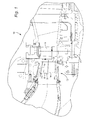
- FIG. 1 there is illustrated a portion of a turbine, generally designated 10, having multiple stages, including a first stage, generally designated 12.
- the first stage includes a plurality of circumferentially spaced nozzles 14, as well as buckets 16 mounted on the rotor 17.
- the first stage nozzles 14 have a plurality of circumferentially spaced airfoils or blades 18 of a particular airfoil shape or profile as specified below.
- each nozzle airfoil shape or profile of each nozzle airfoil includes leading and trailing edges 20 and 22, respectively.
- the nozzle airfoils are disposed between inner and outer side walls 24 and 26, respectively.
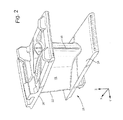
- the side walls and the airfoil between the sidewalls constitute a nozzle segment generally designated 28 in Figure 2.
- Each of the first stage nozzle blades has an airfoil profile defined by a Cartesian coordinate system of X, Y and Z values.
- the coordinate values are set forth in inches in Table I below.
- the Cartesian coordinate system includes orthogonally related X, Y and Z axes.
- the X axis lies along the turbine rotor center line, i.e., the rotor axis.
- the Z axis extends along radii from the center line of the turbine rotor to the X and Y coordinate values for the respective sets of X, Y and Z coordinate values. That is, each Z distance commences at zero along the turbine axis and extends to a point defined by the X and Y coordinate values for those X, Y and Z coordinate values.
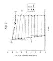
- the airfoil profile sections between the inner and outer side walls are given in eleven sets of X, Y and Z coordinate values, and hence eleven profile sections, represented by the dashed lines in Figure 3.
- Each profile section lies in and conforms to a portion of a surface of revolution about the turbine axis.
- the profile section at that location for a single airfoil lies in a portion of a conical surface of revolution about the turbine axis.
- the profile section per se extends in both an arcuate circumferential direction and a longitudinal direction along the surface portion of the conical surface of revolution about the turbine axis.
- the profile sections defined by the X, Y and Z coordinate values of Table I are therefore not planar but have an arcuate extent in the circumferential direction. Because the profile sections are not taken in planes perpendicular to the turbine axis, the Z coordinate values are different from one another within each set of X, Y and Z coordinate values for each profile section.
- each airfoil section of the eleven sections can be ascertained.
- the profile of each airfoil section of the eleven sections is ascertained.
- the surface profiles at the various surface locations between the profile sections are connected smoothly to one another to form a nominal airfoil profile.
- the tabular values given in Table I are in inches and represent the airfoil profiles at ambient, non-operating or non-hot conditions and are for an uncoated airfoil.
- the X, Y and Z coordinate values given in Table I are in scientific notation represented by the letter E followed by numerical values.
- the numerical values represent the number of spaces to move the decimal point of the number preceding the scientific notation E to give the actual value in inches.
- the plus or minus signs indicate the direction of movement of the decimal points, i.e., the plus sign signals movement of the decimal point to the right and the minus sign signals movement of the decimal point to the left.
- the 78 points defined by the X, Y and Z coordinate values of Table I for each profile section are for a nominal cold or room temperature profile for each profile section of the airfoil.
- Embodiments of the invention are designed to maximize component life whilst having zero impact on turbine performance. Accordingly, fewer replacement components are needed over the useful life of the turbine.
- embodiments of the invention also provide for single nozzle removal and replacement capabilities, in contrast to conventional "doublet" designs in which two airfoils are provided per casting.
- Embodiments of the invention lead to reduced losses due to airfoil shape of around 10%, with zero change in net performance after factoring in higher cooling flow levels. Additionally, there is a predicted increase in part life, resulting in an increase of service intervals from 2 intervals at 900 starts per 24k hours per interval to 3 intervals at 900 starts per 32k hours per interval.
Landscapes
- Engineering & Computer Science (AREA)
- Physics & Mathematics (AREA)
- Fluid Mechanics (AREA)
- Mechanical Engineering (AREA)
- General Engineering & Computer Science (AREA)
- Turbine Rotor Nozzle Sealing (AREA)
- Detergent Compositions (AREA)
- Micro-Organisms Or Cultivation Processes Thereof (AREA)
Applications Claiming Priority (1)
| Application Number | Priority Date | Filing Date | Title |
|---|---|---|---|
| US11/340,577 US7329093B2 (en) | 2006-01-27 | 2006-01-27 | Nozzle blade airfoil profile for a turbine |
Publications (2)
| Publication Number | Publication Date |
|---|---|
| EP1813772A2 true EP1813772A2 (de) | 2007-08-01 |
| EP1813772A3 EP1813772A3 (de) | 2011-08-24 |
Family
ID=37896073
Family Applications (1)
| Application Number | Title | Priority Date | Filing Date |
|---|---|---|---|
| EP07101176A Withdrawn EP1813772A3 (de) | 2006-01-27 | 2007-01-25 | Geometrie einer Turbinenschaufel |
Country Status (5)
| Country | Link |
|---|---|
| US (1) | US7329093B2 (de) |
| EP (1) | EP1813772A3 (de) |
| JP (1) | JP2007198385A (de) |
| CN (1) | CN101008326B (de) |
| MX (1) | MX2007001039A (de) |
Cited By (1)
| Publication number | Priority date | Publication date | Assignee | Title |
|---|---|---|---|---|
| WO2020101774A1 (en) | 2018-08-21 | 2020-05-22 | Chromalloy Gas Turbine Llc | Improved first stage turbine nozzle |
Families Citing this family (40)
| Publication number | Priority date | Publication date | Assignee | Title |
|---|---|---|---|---|
| WO2007141596A2 (en) * | 2005-12-29 | 2007-12-13 | Rolls-Royce Power Engineering Plc | Turbine nozzle blade airfoil geometry |
| US7329093B2 (en) * | 2006-01-27 | 2008-02-12 | General Electric Company | Nozzle blade airfoil profile for a turbine |
| US7329092B2 (en) * | 2006-01-27 | 2008-02-12 | General Electric Company | Stator blade airfoil profile for a compressor |
| US7306436B2 (en) * | 2006-03-02 | 2007-12-11 | Pratt & Whitney Canada Corp. | HP turbine blade airfoil profile |
| US7396211B2 (en) * | 2006-03-30 | 2008-07-08 | General Electric Company | Stator blade airfoil profile for a compressor |
| US7581930B2 (en) * | 2006-08-16 | 2009-09-01 | United Technologies Corporation | High lift transonic turbine blade |
| US7611326B2 (en) * | 2006-09-06 | 2009-11-03 | Pratt & Whitney Canada Corp. | HP turbine vane airfoil profile |
| US7530793B2 (en) * | 2006-10-25 | 2009-05-12 | General Electric Company | Airfoil shape for a compressor |
| US7513748B2 (en) * | 2006-10-25 | 2009-04-07 | General Electric Company | Airfoil shape for a compressor |
| US7572104B2 (en) * | 2006-10-25 | 2009-08-11 | General Electric Company | Airfoil shape for a compressor |
| US7517197B2 (en) * | 2006-10-25 | 2009-04-14 | General Electric Company | Airfoil shape for a compressor |
| US7566202B2 (en) * | 2006-10-25 | 2009-07-28 | General Electric Company | Airfoil shape for a compressor |
| US7520729B2 (en) * | 2006-10-25 | 2009-04-21 | General Electric Company | Airfoil shape for a compressor |
| US7572105B2 (en) * | 2006-10-25 | 2009-08-11 | General Electric Company | Airfoil shape for a compressor |
| US7510378B2 (en) * | 2006-10-25 | 2009-03-31 | General Electric Company | Airfoil shape for a compressor |
| US7527473B2 (en) * | 2006-10-26 | 2009-05-05 | General Electric Company | Airfoil shape for a turbine nozzle |
| US7537434B2 (en) * | 2006-11-02 | 2009-05-26 | General Electric Company | Airfoil shape for a compressor |
| US7497665B2 (en) * | 2006-11-02 | 2009-03-03 | General Electric Company | Airfoil shape for a compressor |
| US7568892B2 (en) * | 2006-11-02 | 2009-08-04 | General Electric Company | Airfoil shape for a compressor |
| US7559748B2 (en) * | 2006-11-28 | 2009-07-14 | Pratt & Whitney Canada Corp. | LP turbine blade airfoil profile |
| US7985053B2 (en) * | 2008-09-12 | 2011-07-26 | General Electric Company | Inlet guide vane |
| US8133016B2 (en) * | 2009-01-02 | 2012-03-13 | General Electric Company | Airfoil profile for a second stage turbine nozzle |
| US8573945B2 (en) * | 2009-11-13 | 2013-11-05 | Alstom Technology Ltd. | Compressor stator vane |
| US8672637B2 (en) * | 2010-08-17 | 2014-03-18 | Hamilton Sundstrand Corporation | Air turbine starter turbine blade airfoil |
| US8864456B2 (en) * | 2011-09-19 | 2014-10-21 | Hamilton Sundstrand Corporation | Turbine nozzle for air cycle machine |
| US9011101B2 (en) | 2011-11-28 | 2015-04-21 | General Electric Company | Turbine bucket airfoil profile |
| US8827641B2 (en) | 2011-11-28 | 2014-09-09 | General Electric Company | Turbine nozzle airfoil profile |
| US8814526B2 (en) | 2011-11-28 | 2014-08-26 | General Electric Company | Turbine nozzle airfoil profile |
| US8740570B2 (en) | 2011-11-28 | 2014-06-03 | General Electric Company | Turbine bucket airfoil profile |
| US8734116B2 (en) | 2011-11-28 | 2014-05-27 | General Electric Company | Turbine bucket airfoil profile |
| US8979499B2 (en) | 2012-08-17 | 2015-03-17 | United Technologies Corporation | Gas turbine engine airfoil profile |
| US20140321979A1 (en) * | 2013-04-24 | 2014-10-30 | Hamilton Sundstrand Corporation | Turbine nozzle piece parts with hvoc coatings |
| CN103557034B (zh) * | 2013-09-30 | 2015-07-15 | 哈尔滨汽轮机厂有限责任公司 | 一种应用于重型中低热值燃机的涡轮第二级导叶片 |
| WO2015112222A2 (en) | 2013-11-04 | 2015-07-30 | United Technologies Corporation | Gas turbine engine airfoil profile |
| US10443393B2 (en) * | 2016-07-13 | 2019-10-15 | Safran Aircraft Engines | Optimized aerodynamic profile for a turbine vane, in particular for a nozzle of the seventh stage of a turbine |
| US10443392B2 (en) * | 2016-07-13 | 2019-10-15 | Safran Aircraft Engines | Optimized aerodynamic profile for a turbine vane, in particular for a nozzle of the second stage of a turbine |
| US10590782B1 (en) * | 2018-08-21 | 2020-03-17 | Chromalloy Gas Turbine Llc | Second stage turbine nozzle |
| US11384640B2 (en) * | 2018-11-26 | 2022-07-12 | General Electric Company | Airfoil shape and platform contour for turbine rotor blades |
| US11015459B2 (en) | 2019-10-10 | 2021-05-25 | Power Systems Mfg., Llc | Additive manufacturing optimized first stage vane |
| US11326460B1 (en) * | 2021-07-15 | 2022-05-10 | Doosan Heavy Industries & Construction Co., Ltd. | Airfoil profile for a turbine nozzle |
Citations (4)
| Publication number | Priority date | Publication date | Assignee | Title |
|---|---|---|---|---|
| EP1312755A2 (de) * | 2001-11-14 | 2003-05-21 | General Electric Company | Profil eines Schaufelblattes für eine zweite Turbinenstufe |
| US6722853B1 (en) * | 2002-11-22 | 2004-04-20 | General Electric Company | Airfoil shape for a turbine nozzle |
| US20040223849A1 (en) * | 2003-05-07 | 2004-11-11 | Urban John Paul | Second stage turbine bucket airfoil |
| EP1503037A2 (de) * | 2003-07-31 | 2005-02-02 | General Electric Company | Schaufelprofil einer Turbinen-Statorschaufel |
Family Cites Families (49)
| Publication number | Priority date | Publication date | Assignee | Title |
|---|---|---|---|---|
| JPH10184304A (ja) * | 1996-12-27 | 1998-07-14 | Toshiba Corp | 軸流タービンのタービンノズルおよびタービン動翼 |
| US5980209A (en) * | 1997-06-27 | 1999-11-09 | General Electric Co. | Turbine blade with enhanced cooling and profile optimization |
| US6461110B1 (en) * | 2001-07-11 | 2002-10-08 | General Electric Company | First-stage high pressure turbine bucket airfoil |
| US6398489B1 (en) * | 2001-02-08 | 2002-06-04 | General Electric Company | Airfoil shape for a turbine nozzle |
| US6474948B1 (en) * | 2001-06-22 | 2002-11-05 | General Electric Company | Third-stage turbine bucket airfoil |
| US6450770B1 (en) * | 2001-06-28 | 2002-09-17 | General Electric Company | Second-stage turbine bucket airfoil |
| US6503059B1 (en) * | 2001-07-06 | 2003-01-07 | General Electric Company | Fourth-stage turbine bucket airfoil |
| US6461109B1 (en) * | 2001-07-13 | 2002-10-08 | General Electric Company | Third-stage turbine nozzle airfoil |
| US6503054B1 (en) * | 2001-07-13 | 2003-01-07 | General Electric Company | Second-stage turbine nozzle airfoil |
| EP1283338B1 (de) * | 2001-08-09 | 2005-03-30 | Siemens Aktiengesellschaft | Gasturbine und Verfahren zum Betreiben einer Gasturbine |
| JP2003106103A (ja) * | 2001-10-02 | 2003-04-09 | Honda Motor Co Ltd | 回転機の静翼 |
| US6685434B1 (en) * | 2002-09-17 | 2004-02-03 | General Electric Company | Second stage turbine bucket airfoil |
| US6715990B1 (en) * | 2002-09-19 | 2004-04-06 | General Electric Company | First stage turbine bucket airfoil |
| US6722852B1 (en) * | 2002-11-22 | 2004-04-20 | General Electric Company | Third stage turbine bucket airfoil |
| US6779977B2 (en) * | 2002-12-17 | 2004-08-24 | General Electric Company | Airfoil shape for a turbine bucket |
| US6887041B2 (en) * | 2003-03-03 | 2005-05-03 | General Electric Company | Airfoil shape for a turbine nozzle |
| US6779980B1 (en) * | 2003-03-13 | 2004-08-24 | General Electric Company | Airfoil shape for a turbine bucket |
| US6739838B1 (en) * | 2003-03-17 | 2004-05-25 | General Electric Company | Airfoil shape for a turbine bucket |
| US6739839B1 (en) * | 2003-03-31 | 2004-05-25 | General Electric Company | First-stage high pressure turbine bucket airfoil |
| US6769878B1 (en) * | 2003-05-09 | 2004-08-03 | Power Systems Mfg. Llc | Turbine blade airfoil |
| US6736599B1 (en) * | 2003-05-14 | 2004-05-18 | General Electric Company | First stage turbine nozzle airfoil |
| US6854961B2 (en) * | 2003-05-29 | 2005-02-15 | General Electric Company | Airfoil shape for a turbine bucket |
| US6808368B1 (en) * | 2003-06-13 | 2004-10-26 | General Electric Company | Airfoil shape for a turbine bucket |
| US6769879B1 (en) * | 2003-07-11 | 2004-08-03 | General Electric Company | Airfoil shape for a turbine bucket |
| US6893216B2 (en) * | 2003-07-17 | 2005-05-17 | General Electric Company | Turbine bucket tip shroud edge profile |
| US6884038B2 (en) * | 2003-07-18 | 2005-04-26 | General Electric Company | Airfoil shape for a turbine bucket |
| US6910868B2 (en) * | 2003-07-23 | 2005-06-28 | General Electric Company | Airfoil shape for a turbine bucket |
| US6857855B1 (en) * | 2003-08-04 | 2005-02-22 | General Electric Company | Airfoil shape for a turbine bucket |
| US6881038B1 (en) * | 2003-10-09 | 2005-04-19 | General Electric Company | Airfoil shape for a turbine bucket |
| US6932577B2 (en) * | 2003-11-21 | 2005-08-23 | Power Systems Mfg., Llc | Turbine blade airfoil having improved creep capability |
| CN1554856A (zh) * | 2003-12-26 | 2004-12-15 | 东方汽轮机厂 | 防固体微粒侵蚀的汽轮机喷嘴静、动叶片及其热处理方法 |
| US7001147B1 (en) * | 2004-07-28 | 2006-02-21 | General Electric Company | Airfoil shape and sidewall flowpath surfaces for a turbine nozzle |
| US7094034B2 (en) * | 2004-07-30 | 2006-08-22 | United Technologies Corporation | Airfoil profile with optimized aerodynamic shape |
| US7186090B2 (en) * | 2004-08-05 | 2007-03-06 | General Electric Company | Air foil shape for a compressor blade |
| US20060216144A1 (en) * | 2005-03-28 | 2006-09-28 | Sullivan Michael A | First and second stage turbine airfoil shapes |
| US7384243B2 (en) * | 2005-08-30 | 2008-06-10 | General Electric Company | Stator vane profile optimization |
| US7722329B2 (en) * | 2005-12-29 | 2010-05-25 | Rolls-Royce Power Engineering Plc | Airfoil for a third stage nozzle guide vane |
| WO2007141596A2 (en) * | 2005-12-29 | 2007-12-13 | Rolls-Royce Power Engineering Plc | Turbine nozzle blade airfoil geometry |
| GB2448087B (en) * | 2005-12-29 | 2011-06-22 | Rolls Royce Power Eng | Second Stage Turbine Airfoil |
| US7632072B2 (en) * | 2005-12-29 | 2009-12-15 | Rolls-Royce Power Engineering Plc | Third stage turbine airfoil |
| WO2007085912A2 (en) * | 2005-12-29 | 2007-08-02 | Rolls-Royce Power Engineering Plc | Airfoil for a first stage nozzle guide vane |
| WO2008035135A2 (en) * | 2005-12-29 | 2008-03-27 | Rolls-Royce Power Engineering Plc | First stage turbine airfoil |
| US7329092B2 (en) * | 2006-01-27 | 2008-02-12 | General Electric Company | Stator blade airfoil profile for a compressor |
| US7329093B2 (en) * | 2006-01-27 | 2008-02-12 | General Electric Company | Nozzle blade airfoil profile for a turbine |
| ITMI20060340A1 (it) * | 2006-02-27 | 2007-08-28 | Nuovo Pignone Spa | Pala di un rotore di un secondo stadio di un compressore |
| US7306436B2 (en) * | 2006-03-02 | 2007-12-11 | Pratt & Whitney Canada Corp. | HP turbine blade airfoil profile |
| US7367779B2 (en) * | 2006-03-02 | 2008-05-06 | Pratt & Whitney Canada Corp. | LP turbine vane airfoil profile |
| US7402026B2 (en) * | 2006-03-02 | 2008-07-22 | Pratt & Whitney Canada Corp. | Turbine exhaust strut airfoil profile |
| US7351038B2 (en) * | 2006-03-02 | 2008-04-01 | Pratt & Whitney Canada Corp. | HP turbine vane airfoil profile |
-
2006
- 2006-01-27 US US11/340,577 patent/US7329093B2/en active Active
-
2007
- 2007-01-25 JP JP2007014823A patent/JP2007198385A/ja not_active Withdrawn
- 2007-01-25 MX MX2007001039A patent/MX2007001039A/es active IP Right Grant
- 2007-01-25 EP EP07101176A patent/EP1813772A3/de not_active Withdrawn
- 2007-01-26 CN CN2007100047027A patent/CN101008326B/zh not_active Expired - Fee Related
Patent Citations (4)
| Publication number | Priority date | Publication date | Assignee | Title |
|---|---|---|---|---|
| EP1312755A2 (de) * | 2001-11-14 | 2003-05-21 | General Electric Company | Profil eines Schaufelblattes für eine zweite Turbinenstufe |
| US6722853B1 (en) * | 2002-11-22 | 2004-04-20 | General Electric Company | Airfoil shape for a turbine nozzle |
| US20040223849A1 (en) * | 2003-05-07 | 2004-11-11 | Urban John Paul | Second stage turbine bucket airfoil |
| EP1503037A2 (de) * | 2003-07-31 | 2005-02-02 | General Electric Company | Schaufelprofil einer Turbinen-Statorschaufel |
Cited By (2)
| Publication number | Priority date | Publication date | Assignee | Title |
|---|---|---|---|---|
| WO2020101774A1 (en) | 2018-08-21 | 2020-05-22 | Chromalloy Gas Turbine Llc | Improved first stage turbine nozzle |
| EP3841285A4 (de) * | 2018-08-21 | 2022-03-23 | Chromalloy Gas Turbine LLC | Verbesserte erststufen-turbinendüse |
Also Published As
| Publication number | Publication date |
|---|---|
| EP1813772A3 (de) | 2011-08-24 |
| CN101008326A (zh) | 2007-08-01 |
| JP2007198385A (ja) | 2007-08-09 |
| MX2007001039A (es) | 2009-02-05 |
| CN101008326B (zh) | 2012-04-25 |
| US7329093B2 (en) | 2008-02-12 |
| US20070177981A1 (en) | 2007-08-02 |
Similar Documents
| Publication | Publication Date | Title |
|---|---|---|
| EP1813772A2 (de) | Geometrie einer Turbinenschaufel | |
| US7396211B2 (en) | Stator blade airfoil profile for a compressor | |
| US7329092B2 (en) | Stator blade airfoil profile for a compressor | |
| US7494323B2 (en) | Airfoil shape for a compressor | |
| US7001147B1 (en) | Airfoil shape and sidewall flowpath surfaces for a turbine nozzle | |
| US6779980B1 (en) | Airfoil shape for a turbine bucket | |
| US6715990B1 (en) | First stage turbine bucket airfoil | |
| US7494321B2 (en) | Airfoil shape for a compressor | |
| US6558122B1 (en) | Second-stage turbine bucket airfoil | |
| US7566202B2 (en) | Airfoil shape for a compressor | |
| US7524170B2 (en) | Airfoil shape for a compressor | |
| US7494322B2 (en) | Airfoil shape for a compressor | |
| US6503059B1 (en) | Fourth-stage turbine bucket airfoil | |
| US6503054B1 (en) | Second-stage turbine nozzle airfoil | |
| EP1916386A2 (de) | Schaufelprofil für einen Verdichter | |
| EP1921262A2 (de) | Flügelform für einen Verdichter | |
| EP1921258A2 (de) | Flügelform für einen Verdichter | |
| JP2008106749A (ja) | 圧縮機用の翼形状 | |
| EP1921266A2 (de) | Turbinenschaufelform für einen Kompressor | |
| EP1918518A2 (de) | Turbinenschaufelform für einen Kompressor | |
| EP1921260A2 (de) | Flügelform für einen Verdichter | |
| EP1918519A2 (de) | Flügelform für einen Verdichter | |
| JP2008115854A (ja) | 圧縮機用の翼形状 | |
| EP1916384A2 (de) | Schaufelprofil für einen Verdichter | |
| EP1918513A2 (de) | Turbinenschaufelform für einen Kompressor |
Legal Events
| Date | Code | Title | Description |
|---|---|---|---|
| PUAI | Public reference made under article 153(3) epc to a published international application that has entered the european phase |
Free format text: ORIGINAL CODE: 0009012 |
|
| AK | Designated contracting states |
Kind code of ref document: A2 Designated state(s): AT BE BG CH CY CZ DE DK EE ES FI FR GB GR HU IE IS IT LI LT LU LV MC NL PL PT RO SE SI SK TR |
|
| AX | Request for extension of the european patent |
Extension state: AL BA HR MK RS |
|
| PUAL | Search report despatched |
Free format text: ORIGINAL CODE: 0009013 |
|
| AK | Designated contracting states |
Kind code of ref document: A3 Designated state(s): AT BE BG CH CY CZ DE DK EE ES FI FR GB GR HU IE IS IT LI LT LU LV MC NL PL PT RO SE SI SK TR |
|
| AX | Request for extension of the european patent |
Extension state: AL BA HR MK RS |
|
| RIC1 | Information provided on ipc code assigned before grant |
Ipc: F01D 5/14 20060101AFI20110720BHEP |
|
| AKY | No designation fees paid | ||
| REG | Reference to a national code |
Ref country code: DE Ref legal event code: R108 Effective date: 20120502 |
|
| STAA | Information on the status of an ep patent application or granted ep patent |
Free format text: STATUS: THE APPLICATION IS DEEMED TO BE WITHDRAWN |
|
| 18D | Application deemed to be withdrawn |
Effective date: 20120225 |