EP1813454A2 - Hatchback door structure for vehicle - Google Patents
Hatchback door structure for vehicle Download PDFInfo
- Publication number
- EP1813454A2 EP1813454A2 EP07001416A EP07001416A EP1813454A2 EP 1813454 A2 EP1813454 A2 EP 1813454A2 EP 07001416 A EP07001416 A EP 07001416A EP 07001416 A EP07001416 A EP 07001416A EP 1813454 A2 EP1813454 A2 EP 1813454A2
- Authority
- EP
- European Patent Office
- Prior art keywords
- lateral beam
- frame
- hatchback door
- inner panel
- door structure
- Prior art date
- Legal status (The legal status is an assumption and is not a legal conclusion. Google has not performed a legal analysis and makes no representation as to the accuracy of the status listed.)
- Granted
Links
- 239000005357 flat glass Substances 0.000 claims abstract description 6
- 239000000463 material Substances 0.000 claims description 14
- 238000003466 welding Methods 0.000 description 21
- 230000002787 reinforcement Effects 0.000 description 17
- 238000004519 manufacturing process Methods 0.000 description 10
- 239000011521 glass Substances 0.000 description 9
- 238000005452 bending Methods 0.000 description 6
- 238000000034 method Methods 0.000 description 6
- 230000008569 process Effects 0.000 description 6
- 230000008901 benefit Effects 0.000 description 5
- 230000006872 improvement Effects 0.000 description 5
- 230000000694 effects Effects 0.000 description 4
- 230000015572 biosynthetic process Effects 0.000 description 3
- 230000000052 comparative effect Effects 0.000 description 3
- 230000004048 modification Effects 0.000 description 3
- 238000012986 modification Methods 0.000 description 3
- 230000009467 reduction Effects 0.000 description 3
- 229910000838 Al alloy Inorganic materials 0.000 description 2
- 238000013459 approach Methods 0.000 description 2
- 238000013461 design Methods 0.000 description 2
- 238000005520 cutting process Methods 0.000 description 1
- 230000007423 decrease Effects 0.000 description 1
- 230000003247 decreasing effect Effects 0.000 description 1
- 239000000446 fuel Substances 0.000 description 1
- 238000009957 hemming Methods 0.000 description 1
- 229910052751 metal Inorganic materials 0.000 description 1
- 239000002184 metal Substances 0.000 description 1
- 230000003014 reinforcing effect Effects 0.000 description 1
- 238000009751 slip forming Methods 0.000 description 1
- 238000000638 solvent extraction Methods 0.000 description 1
- 238000012546 transfer Methods 0.000 description 1
- 239000013585 weight reducing agent Substances 0.000 description 1
Images









Classifications
-
- B—PERFORMING OPERATIONS; TRANSPORTING
- B60—VEHICLES IN GENERAL
- B60J—WINDOWS, WINDSCREENS, NON-FIXED ROOFS, DOORS, OR SIMILAR DEVICES FOR VEHICLES; REMOVABLE EXTERNAL PROTECTIVE COVERINGS SPECIALLY ADAPTED FOR VEHICLES
- B60J5/00—Doors
- B60J5/10—Doors arranged at the vehicle rear
- B60J5/101—Doors arranged at the vehicle rear for non-load transporting vehicles, i.e. family cars including vans
- B60J5/107—Doors arranged at the vehicle rear for non-load transporting vehicles, i.e. family cars including vans constructional details, e.g. about door frame, panels, materials used, reinforcements
-
- B—PERFORMING OPERATIONS; TRANSPORTING
- B60—VEHICLES IN GENERAL
- B60J—WINDOWS, WINDSCREENS, NON-FIXED ROOFS, DOORS, OR SIMILAR DEVICES FOR VEHICLES; REMOVABLE EXTERNAL PROTECTIVE COVERINGS SPECIALLY ADAPTED FOR VEHICLES
- B60J5/00—Doors
- B60J5/04—Doors arranged at the vehicle sides
- B60J5/042—Reinforcement elements
- B60J5/0422—Elongated type elements, e.g. beams, cables, belts or wires
- B60J5/0423—Elongated type elements, e.g. beams, cables, belts or wires characterised by position in the lower door structure
- B60J5/0429—Elongated type elements, e.g. beams, cables, belts or wires characterised by position in the lower door structure the elements being arranged diagonally
-
- B—PERFORMING OPERATIONS; TRANSPORTING
- B60—VEHICLES IN GENERAL
- B60J—WINDOWS, WINDSCREENS, NON-FIXED ROOFS, DOORS, OR SIMILAR DEVICES FOR VEHICLES; REMOVABLE EXTERNAL PROTECTIVE COVERINGS SPECIALLY ADAPTED FOR VEHICLES
- B60J5/00—Doors
- B60J5/04—Doors arranged at the vehicle sides
- B60J5/042—Reinforcement elements
- B60J5/0455—Reinforcement elements integrated in door structure or other door elements, e.g. beam-like shapes stamped in inner door panel
-
- B—PERFORMING OPERATIONS; TRANSPORTING
- B60—VEHICLES IN GENERAL
- B60J—WINDOWS, WINDSCREENS, NON-FIXED ROOFS, DOORS, OR SIMILAR DEVICES FOR VEHICLES; REMOVABLE EXTERNAL PROTECTIVE COVERINGS SPECIALLY ADAPTED FOR VEHICLES
- B60J5/00—Doors
- B60J5/10—Doors arranged at the vehicle rear
- B60J5/101—Doors arranged at the vehicle rear for non-load transporting vehicles, i.e. family cars including vans
Definitions
- the present invention relates to a hatchback door structure for vehicles, which is light and rigid.
- a hatchback door structure which includes an inner panel in which a lateral beam is integrally formed with a frame which has a shape outlining an outer shape of the hatchback door so that the lateral beam divides the frame into an upper portion and a lower portion (for example, refer to paragraphs 0010 to 0015 and FIG. 1 of Japanese Patent Laid-Open Publication Kokai No. H08-258568 ).
- FIG. 14 is a schematic illustration of a vehicle seen from a backside for explaining a conventional hatchback door structure.
- a hatch back door 201 of a vehicle V includes an inner panel 206 comprising a frame 209 and a lateral beam 218.
- a window glass 207 is fixed in an opening 212a zoned by the frame 209 and the lateral beam 218 on an upper side of the lateral beam 218.
- a pair of joint reinforcements 200a is disposed in an opening 212b zoned by the frame 209 and the lateral beam 218 on a lower side of the lateral beam 218, a pair of joint reinforcements 200a is disposed.
- a lower end ⁇ vf each reinforcement 200a is welded on the frame 209 through a lock reinforcement 200b which is fixed at a center of a bottom side of the frame 209.
- the pair of the joint reinforcements 200a extends in a V-shape to each upper corner of the opening 212b.
- An upper end of the joint reinforcement 200a is welded on the frame 209 and the lateral beam 218 through a corresponding corner reinforcement 200c which is fixed on a corresponding upper corner of the opening 212b.
- a rigidity of the inner panel 206 is increased by disposing the pair of joint reinforcements 200a in the opening 212b.
- a hatchback door fitted up on a tailgate in a rear part of a vehicle is jointed to the vehicle with a hinge structure.
- An opening-closing motion of the hatchback door is performed by rotating the door about the hinge located at the upper end of the door.
- These types of hatchback doors are required to increase the rigidity for improving collision strength and for avoiding muffled sounds when a vehicle runs a punishing road.
- the hatchback door must be light for reducing fuel consumption of a vehicle and improving easiness of the opening-closing motion of the door. Because of the above reasons, most of conventional hatchback doors for vehicles have a structure combining a thin outer panel and a thin inner panel which has openings, and the structure is reinforced by utilizing shapes of the both panels.
- FIG. 15 is a perspective view showing an example of an inner panel which configures a conventional hatchback door structure.
- a frame 304c which outlines an outer shape of the hatchback door is formed.
- a window frame 305c is formed in an upper portion of the frame 304c and an opening 308c in which a window glass is to be set is disposed.
- An opening 309c is disposed in a lower portion of the inner panel 302c for weight saving.
- a lateral beam 306c which separates the two openings 308c, 309c is formed.
- the lateral beam 306c is integrally formed with the frame 304c by press-forming.
- the lateral beam 306c is a component for increasing a rigidity of the inner panel 302c against a lateral bending.
- Examples disclosed in Japanese Patent No. 3013921 and Japanese Unexamined Patent Publication Kohyo No. 11-514613 have identical contents with that of the aforementioned example, in which openings of the inner panel disposed for weight saving are reinforced by a beam or reinforcement and the like.
- the discrete joint reinforcements 200a are welded on the frame 209 and the lateral beam 218, while requiring other members such as the lock reinforcement 200b and the corner reinforcements 200c for welding the joint reinforcements 200a. Therefore, the manufacturing cost becomes high, and at the same time, a weight of the hatchback door structure 201 increases. Further, a working process increases due to necessity of the welding.
- the first problem is as follows.
- a formation of cut-and-turned-up walls (hereinafter, referred to as louvered-walls) 311c with a sufficient height formed on peripheries of the openings 308c, 309c of the inner panel 302c is difficult due to a limitation in press formability, unless a highly-ductile material is used for the panel. Therefore, an increase of the rigidity of the inner panel 302c is limited.
- the second is as follows. Corners 312c, where the lateral beam 306c and the frame 304c of the inner panel 302c are jointed, are required to have a radius R larger than a predetermined value. As a result, a size of the opening 308c for the rear glass window should be made smaller, which narrows a rearward visibility of a vehicle.
- the third is as follows. Improvement of the rigidity of the inner panel 302c against bending in a tangential direction relative to a circular path formed by the rotation circle of the hatchback door is difficult. When a hatchback door is closed, the hatchback door receives a force in the tangential direction. Therefore, if the louvered-walls 311c of the lateral beam 306c are formed in parallel with the tangential direction, the vibrations of the hatchback door are effectively suppressed.
- louvered-walls 311c of the lateral beam 306c may not be inclined in the effective direction for suppressing the vibrations of the hatchback door when the door is closed.
- the fourth is as follows. Since the lateral beam 306c is integrally formed with the inner panel 302c, a panel thickness of the lateral beam 306c can not be made difficult from that of the inner panel 302c. For example, changes in design to thin the panel thickness of the lateral beam 306c for the weight saving thinner than that of the frame 304c can not be performed.
- a hatchback door structure for vehicles which comprises: an inner panel which is arranged on an inner side of a vehicle; and an outer panel which is arranged on an outer side of the vehicle, wherein the inner panel comprises a frame which has a shape outlining an outer shape of the hatchback door, and a pair of stiffening ribs which is integrally formed with the frame and extends approximately in a V-shape to both side portions of the frame from a bottom side of the frame.
- the inner panel is formed so that the pair of stiffening ribs extends approximately in a V-shape from the bottom side to the both side portions of the frame which has the shape outlining the outer shape of the hatchback door. That is, in the hatchback door structure, by securing an opening as large as possible on the inner panel due to utilization of the frame and stiffening ribs, the weight saving can be achieved, as well as increase in the rigidity.
- a smoothly continuous surface portion may preferably but not necessarily be formed at a connection part of a side portion of the frame and stiffening rib.
- the pair of the stiffening ribs may preferably but not necessarily extend approximately in a V-shape from a locking device fixing portion which is formed on the bottom part of the frame to each of the couple of side portions of the frame, the locking device fixing portion being configured for fixing a locking device.
- the stiffening ribs extend approximately in a V-shape from the locking device fixing portion, the rigidity is further increased.
- the inner panel may preferably but not necessarily have louvered-walls which are integrally formed with the inner panel, protrude outward to an outer panel side and jointed to the outer panel.
- the louvered-walls formed in the inner panel are jointed to the outer panel, the rigidity is further increased.
- the louvered-walls are formed by cutting and turning up the panel when they are integrally formed with the inner panel, the louvered-walls can be formed easily at desired positions and with optimal shapes.
- a first opening may preferably but not necessarily be defined by the stiffening ribs and the frame, on a lower side of one of the stiffening ribs, a second opening be defined by the one of the stiffening ribs and the frame, and on a lower side of the other stiffening rib, a third opening be defined by the other stiffening rib and the frame.
- the hatchback door structure since the first opening, the second opening, and the third opening are formed on the inner panel, openings can be formed as large as possible to cover broader area of the inner panel. As a result, the hatchback door structure can achieve the weight saving, as well as improvement of the rigidity.
- the inner panel further may preferably but not necessarily comprise a lateral beam which extends between jointing portions of the side portions of the frame and stiffening ribs, and is integrally formed with the inner panel by press-forming.
- the lateral beam is formed to extend between the jointing portions of the side portions of the frame and the stiffening ribs, the rigidity is further increased.
- the lateral beam is integrally formed with the frame and the stiffening ribs, a manufacturing process of the hatchback door structure (inner panel) can be simplified.
- the inner panel may preferably but not necessarily be integrally formed by press-forming, and further comprise a discrete lateral beam which extends between jointing portions of the side portions of the frame and stiffening ribs.
- the press-forming of the inner panel can be performed easily and a flexibility in the press-forming can be increased. Accordingly, a larger opening can be secured in the inner panel.
- the discrete lateral beam may preferably but not necessarily be formed in a circular arc so that the lateral beam protrudes in convex to an outer side of a vehicle, and a size of a cross section of the lateral beam gradually becomes smaller from a center to both ends of the lateral beam.
- the discrete lateral beam is formed in a circular arc so that the lateral beam protrudes in convex to an outer side of a vehicle, and curves along an outer side of the hatchback door. If a heavy object such as a motor of a wiper is fixed at a center portion of the lateral beam, a large stress is generated at the center portion. In the hatchback door structure, even if the size of the cross section of the center portion is increased for supporting the heavy object with the center portion of the lateral beam, the weight saving of the lateral beam can be achieved, because the size of the cross section of the lateral beam gradually becomes smaller from the center to both ends of the lateral beam.
- the discrete lateral beam may preferably but not necessarily be arranged so that a protruded direction of the lateral beam which is approximately perpendicular to an extending direction of the lateral beam is directed along an opening-closing direction of the hatchback door.
- the lateral beam has a sufficient rigidity against a stress applied to the lateral beam, especially, when closing the hatchback door.
- Each fixing portion of the discrete lateral beam on each jointing portion may preferably but not necessarily be formed so that the each fixing portion is arranged on a same plane defined in a vehicle width direction.
- the discrete lateral beam may preferably but not necessarily be formed by press-forming, and a window frame on which a window glass is fixed be formed in an upper portion of the frame.
- the inner panel and the lateral beam to be jointed to the inner panel can be formed independently. Therefore, each of the members (inner panel and lateral beam) can be formed in an optimal shape for increasing the rigidity of the hatchback door structure.
- the discrete lateral beam and the inner panel can be formed with different press directions to each other.
- the discrete lateral beam may preferably but not necessarily be fixed at approximately right angle against the frame of the inner panel at both bottom corners of the window frame.
- an area of the glass window at the bottom corners can be enlarged. As a result, a visibility in the bottom corners of the glass window can be improved.
- Structures of the inner panel and the discrete lateral beam may preferably but not necessarily have different cross sectional widths to each other in an inside-outside direction of the hatchback door.
- the structures of the frame of the inner panel can be designed thicker in the inside-outside direction of the hatchback door. As a result, the rigidity of the hatchback door structure can be increased.
- the inner panel and the discrete lateral beam may preferably but not necessarily have different panel thicknesses to each other.
- the weight saving of the hatchback door structure can be achieved by thinning the panel thickness of the lateral beam.
- a material of the inner panel and a material of the discrete lateral beam may preferably but not necessarily be different to each other.
- the weight saving of the hatchback door structure can be achieved by forming the lateral beam with, for example, aluminum alloy.
- a hatchback door structure for vehicles according to the present invention can achieve the weight saving, while maintaining a sufficient rigidity. Further, the working process and manufacturing cost of the hatchback door structure can be reduced.
- the press-formability of the inner panel can be improved and the degree of freedom of the inner panel shape can be increased without using a highly-ductile panel material.
- the rigidity of the inner panel can be further increased.
- the direction of the press-forming of the discrete lateral beam can be optimized for increasing the rigidity of the hatchback door which is necessary for suppressing the vibrations of the hatchback door at closing the door.
- a panel thickness of the discrete lateral beam can be changed for, for example, the weight saving.
- FIG. 1 is a partial perspective view of a vehicle to which a hatchback door structure according to the first embodiment is applied.
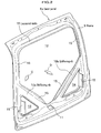
- FIG. 2 is a perspective view showing an inner panel, seen from outside a vehicle, which configures a hatchback door structure according to the embodiment.
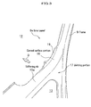
- FIG. 3 is a partial perspective view showing a frame of an inner panel around a side and stiffening rib portions seen from inside a vehicle, that is, a portion indicated by an arrow C in FIG. 2.
- a hatchback door structure 1a is applied to a hatchback door 2 for opening and closing a tailgate opening 3 of a vehicle V.
- the hatchback door 2 has a flip-up structure which rotates about hinges 4, 4 by jointing an upper periphery of the hatchback door 2 and an upper periphery of the tailgate opening 3 with a pair of the hinges 4, 4.
- a locking device (not shown) is disposed for locking the hatchback door 2 to a vehicle body at a closing position of the door.
- the hatchback door structure 1a includes an outer panel 5 which is arranged on an outer side of the hatchback door 2 and forms an outer side surface of the vehicle V, and an inner panel 6a arranged on an inner side of the outer panel 5.
- the hatchback door 1a further includes a window 7 to be completed by fitting a glass in an upper portion of the hatchback door 2, and a wiper 8 arranged in a lower portion of the window 7.
- the inner panel 6a includes a frame 9 which outlines an outer shape of the hatchback door 2, and a pair of stiffening ribs 10a, 10b (hereinafter, referred to as "stiffening rib 10" when the stiffening ribs are not specified) which are integrally formed with the frame 9.
- the frame 9 is formed by press-forming of a metal plate, and, in plane view, has an outer contour in approximately a rectangular shape, as well as an opening in approximately a rectangular shape inside the frame 9.
- a locking device fixing portion 11 is disposed at a bottom center of the frame 9 for fixing the locking device (not shown).
- the stiffening ribs 10a, lOb extend in approximately a V-shape from the bottom of the frame 9, specifically extend from the locking device fixing portion 11 to both sides of the frame 9. Meanwhile, in the embodiment, the both sides of the frame 9 to which the stiffening ribs 10a, 10b are connected correspond to positions of both corners on a lower side of the window 7 (see FIG. 1).
- a first opening 12 is defined by upper sides of the stiffening ribs 10a, 10b and the frame 9
- a second opening 13 is defined by a lower side of one stiffening rib 10a and the frame 9
- a third opening 14 is defined by a lower side of another stiffening rib 10b and the frame 9.
- the first opening 12 according to the embodiment has a pentagonal shape and the second opening 13 and third opening 14 are triangle, in plane view.
- the inner panel 6a includes a plurality of cut-and-turned-up walls (hereinafter, referred to as louvered-walls) 15 on peripheries of the first opening 12, the second opening 13, and the third opening 14.
- the louvered-walls 15 are formed to turn up in a direction of the outer panel 5 (refer to FIG. 1), that is, in a direction D (refer to FIG. 2) toward outside a vehicle.
- the louvered-walls 15 are formed to turn up from the frame 9 and each stiffening rib 10a, 10b so as to surround the first opening 12.
- the louvered-walls 15 of the second opening 13 and third opening 14 are formed to turn up from the frame 9. Ends of the louvered-walls 15 are jointed to the outer panel 5 (refer to FIG. 1).
- the inner panel 6a has a curved surface portion 16 which is smoothly and continuously formed at a connection part of a side portion of the frame 9 and the stiffening rib 10a.
- the curved surface portion 16 corresponds to a "surface portion”.
- another smoothly continuous curved surface portion (not shown) is also formed at a connection part of a side portion of the frame 9 and the stiffening rib 10b shown in FIG. 2 in the same manner as the curved surface portion 16 in FIG. 3.
- the inner panel 6a of the hatchback door structure 1a according to the first embodiment is also used for a hatchback door structure 1b (refer to FIG. 4) according to a second embodiment, which will be described later.
- the inner panel 6a has a lateral beam fixing portion 19 on which a lateral beam 18(refer to FIG. 4), which will be described later, is fixed.
- the lateral beam fixing portion 19 is formed on a jointing portion 17 of the frame 9 and the stiffening rib 10, and specifically, it is formed to rise from a periphery on a side of the direction D (outer side of a vehicle) of the curved surface portion 16 to the first opening 12.
- the inner panel 6a is formed so that the pair of the stiffening ribs 10a, 10b extend to the both sides in approximately a V-shape from the bottom side of the frame 9 which outlines the outer shape of the hatchback door 2, the first opening 12, the second opening 13, and the third opening 14 are formed in the inner panel 6a (refer to FIG. 1). That is, in the hatchback door structure 1a, a weight saving as well as increase in the rigidity is achieved by disposing an opening as large as possible on the inner panel 6a due to utilization of the frame 9 and the stiffening ribs 10a, lOb.
- the louvered-walls 15 formed on the peripheries of the first opening 12, the second opening 13, and the third opening 14 are jointed to the outer panel 5 (refer to FIG. 1), the rigidity can be further improved, while ensuring the weight saving by disposing an opening as large as possible on the inner panel 6a.
- the louvered-walls 15 since the louvered-walls 15 are turned up on the peripheries of the first opening 12, the second opening 13, and the third opening 14 in the hatchback door structure 1a, the louvered-walls 15 can be formed simultaneously with the formation of the first opening 12, the second opening 13, and the third opening 14, and can be formed easily in desired positions with optimal shapes.
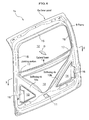
- FIG. 4 is a perspective view showing an inner panel, seen from outside a vehicle, which configures a hatchback door structure according to a second embodiment of the present invention.
- FIG. 5 is a cross sectional view taken along a line X-X of FIG. 4.
- FIG. 6 is a side view of an inner panel according to the second embodiment. Meanwhile, FIG. 6 shows a state in which hinges are fixed on an inner panel. A vehicle to which the inner panel is fitted up is shown with a dashed-two dotted line.
- a configuration of the structure is identical to that of the first embodiment except a presence of a lateral beam on the inner panel. Therefore, the inner panel will be mainly explained.
- a component identical to that of the first embodiment is labeled a same symbol, and the detailed explanation will be omitted.
- a lateral beam 18 is fixed on the inner panel 6a so that the lateral beam 18 extends between the jointing portions 17, 17 of side portions of the frame 9 and the stiffening ribs 10a, 10b.
- the lateral beam 18 is formed in a circular arch which is convex in a direction D directed to outside a vehicle, that is, formed in a curved shape outlining an outer surface (outer surface of the outer panel 5, refer to FIG. 1) of the hatchback door 2 (refer to FIG. 2).
- the lateral beam 18 is a discrete member which is different from the frame 9 and the stiffening ribs 10a, 10b.
- Each end of the lateral beam 18 is fixed on the lateral beam fixing portions 19 (refer to FIG.
- the lateral beam 18 is fixed on the lateral beam fixing portions 19 from outside a vehicle.
- the lateral beam 18 may also be fixed from inside a vehicle.
- a size of a cross section of the lateral beam 18 gradually becomes larger from both ends to a center portion. That is, a thickness of the lateral beam 18 in a direction protruded outside a vehicle gradually becomes thicker as a position of the cross section approaches the center portion from the both ends (gradually becomes thinner from the center portion to the both ends).
- a heavy object such as a motor (not shown) of the wiper 8 may be mounted on the center portion of the lateral beam 18.
- Each of the lateral beam fixing portions 19, 19 on the jointing portions 17, 17 is disposed on a same plane F which is defined in a width direction of a vehicle.
- the lateral beam 18 is arranged so that a protruding direction H, which is approximately perpendicular to an extending direction G (refer to FIG. 5) of the lateral beam 18, is directed along an opening-closing direction J of the hatchback door 2.
- the press-forming of the inner panel 6a can be easily performed by forming the lateral beam 18 as a discrete member which is different from the frame 9 and the stiffening ribs 10a, 10b.
- a larger opening first opening 12
- first opening 12 can be secured due to increase in the level of freedom of the press-forming.
- the lateral beam 18 is curved in a circular arch, and the size of the cross section gradually increases from the both ends to the center portion (see FIG. 5). Therefore, even if a large stress is applied to the center portion of the lateral beam 18 by fixing a heavy object such as a motor (not shown) of the wiper 8, the lateral beam 18 can support the stress due to the rigidity. In other words, since the size of the cross section of the lateral beam 18 gradually decreases as a position of the cross section approaches the both ends from the center portion, the weight saving of the lateral beam 18 also can be achieved.
- the lateral beam 18 is arranged so that the protruding direction H (refer to FIG.6), which is approximately perpendicular to the extending direction G of the lateral beam 18, is directed along the opening-closing direction J of the hatchback door 2, the lateral beam 18 can sufficiently support a load applied thereon, especially when the hatchback door 2 is closed.
- each of the lateral beam fixing portions 19, 19 (refer to FIG. 5) of the lateral beam 18 is disposed on the same plane F which is defined in the width direction of a vehicle. Therefore, the lateral beam 18 can equally transfer a load applied thereon to each of the lateral beam fixing portions 19, 19 when the hatchback door 2 is closed. As a result, the load applied to the lateral beam fixing portions 19, 19 can be equally dispersed.
- the lateral beam 18 since the lateral beam 18 is fixed on the same plane F, the positioning of the lateral beam 18 relative to the jointing portion 17 becomes easier, thereby resulting in improvement of fixing workability of the lateral beam 18.
- the louvered-walls 15 of the inner panel 6a are formed on the peripheries of all openings: the first opening 12, the second opening 13, and the third opening 14.
- the louvered-walls 15 may be formed on the peripheries of at least one of these openings.
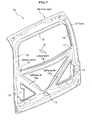
- FIG. 7 is a perspective view of an inner panel, seen from outside a vehicle, which configures a hatchback door structure according to another embodiment of the present invention.
- the lateral beam 18 extending between the jointing portions 17, 17 is integrally formed with the inner panel 6b by press-forming.
- the manufacturing process of the hatchback door structure 1c (inner panel 6b) can be simplified, and at the same time, the rigidity can be increased.
- the stiffening ribs 10a, 10b extend approximately straight.
- the stiffening ribs 10a, 10b may extend with a curvature within a range not to spoiling the purposes of the present invention.
- FIG. 8 is a schematic view of a vehicle, seen from backward of the vehicle, to which a hatchback door structure according to the third embodiment of the present invention is fitted up.
- a hatchback door structure 101a according to the third embodiment is configured with an inner panel 102a and an outer panel 103.
- the hatchback door structure 101a is fitted up to a vehicle V with hinges 114.
- the inner panel 102a and the outer panel 103 are assembled by a hemming process or spot-welding and the like.
- a frame 104a which outlines the hatchback door structure 101a along its outer shape is formed.
- a window frame 105a on which a glass window 107 is fixed is formed, and a lateral beam 106a is fixed on the frame 104a.
- a locking device fixing portion 110 is formed at a bottom of the frame 104a.
- FIG. 9 is a perspective view of an inner panel which is used for a hatchback door structure according to the third embodiment.
- the window frame 105a is formed in an upper portion of the frame 104a configuring the inner panel 102a.
- the frame 104a is formed by press-forming.
- a discrete lateral beam 106a is fixed from outside a vehicle by spot welding. Therefore, the lateral beam 106a is fixed between the pair of the welding portions 113, 113 across an opening.
- the lateral beam 106a is fixed from outside a vehicle so that strength of the hatchback door against an impact at closing the hatchback door is increased.
- the lateral beam 106a may be fixed on the welding portions 113, 113 of the window frame 105a from inside a vehicle.
- louvered-walls 111a On an upper side of the lateral beam 106a, an opening 108a in which a glass window is fixed is disposed. In addition, on a lower side of the lateral beam 106a, an opening 109a is disposed. On peripheries of these openings 108a, 109a, cut-and-turned-up walls (hereinafter referred to as louvered-walls) 111a are formed.
- the louvered-walls 111a have effects to increase a rigidity of the inner panel 102a against a bending.
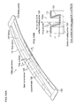
- FIG. 10A is a perspective view of a discrete lateral beam 106a which is used for the third embodiment.
- FIG. 10B is a cross sectional view of the lateral beam 106a used for the embodiment, taken along a line N-N at the center portion of the lateral beam 106a.
- the lateral beam 106a is a member formed by press-forming as a discrete member which is different from the frame 104a of the inner panel 102a (refer to FIG. 8 and FIG. 9).
- the lateral beam 106a has a pair of welding portions 123, 123 on both ends. The pair of welding portions 123, 123 is on a same plane and spot-welded on the window frame 105a which is formed on the frame 104a which configures the inner panel 102a (refer to FIG. 9).
- a portion between the pair of welding portions 123, 123 is a beam portion 121.
- a pair of louvered-walls 122 is formed in the beam portion 121.
- the louvered-walls 122 are disposed for increasing the rigidity of the inner panel 102a against a lateral bending.
- the louvered-walls 122 become higher from each end of the beam portion 121 to a center portion.
- the louvered-walls 122 have the maximum height L3 at a center of the beam portion 121.
- the lateral beam 106a is formed in an arch in which a size of a cross section of the lateral beam 106a becomes maximum at the center and minimum at the both ends of the beam portion 121.
- the lateral beam 106a is formed as a discrete member different from the frame 104a, a level of freedom of the shape design becomes higher than that of the conventional lateral beam 306c (refer to FIG. 15).
- the louvered-walls 122 are made higher, a rigidity of the lateral beam 106a against a bending can be maintained, even if the lateral beam 106a is formed using a thinner panel material than that of the frame 104a by press-forming.
- the lateral beam 106a has a superior press formability since it is formed as a discrete member by press-forming. Therefore, a formation of holes for weight saving on a bottom 124 and an upper curved portion 125 of the beam portion 121 can be performed relatively easily.
- a hole for fixing for example, a motor of a wiper may be formed on the upper curved portion 125 of the lateral beam 106a in some case, and any portion of the upper curved portion 125 can be used to form the hole because of the excellent press formability.
- a fixing weld-nut or the like can be welded in advance on the upper curved portion 125 of the lateral beam 106a.
- a direction of press-forming (hereinafter, referred to as press direction) forms a constant angle ⁇ with a direction perpendicular to a surface of a pair of the welding portions 123, 123.
- press direction a direction of press-forming
- the press direction of the lateral beam 106a makes the angle ⁇ with a vertical direction to the surface of the welding portions 123, 123. Therefore, surfaces of the louvered-walls 122 which are formed by the press-forming are not perpendicular to the surface of the pair of the welding portions 123, 123.
- the hatchback door structure 101a including the inner panel 102a When the hatchback door structure 101a including the inner panel 102a is fitted up on the vehicle V, the hatchback door structure 101a rotates about the hinges 114 which connect the hatchback door structure 101a to the vehicle V.
- the press direction is determined to form the angle ⁇ with the vertical direction of the surface of the pair of the welding portions 123, 123 so that the surfaces of the louvered-walls 122 become in parallel with a tangential direction of a rotation circle of the hatchback door.
- FIG. 11 is a side view of an inner panel 102a, seen from a direction of an arrow A in FIG. 9, to be used for the third embodiment.
- the angle ⁇ between the press direction of the lateral beam 106a shown in FIG. 10B and the vertical direction to the surface of the pair of welding portions 123, 123 corresponds to an angle which is formed between the surface of the pair of welding portions 123, 123 and a line I which connects the center of the lateral beam 106a and the center between the two hinges 114. Due to the above, the press direction of the lateral beam 106a is in parallel with the tangential direction of the rotation circle of the hatchback door about the hinges 114 of the inner panel 102a.
- the hatchback door structure 101a When the hatchback door is closed, the hatchback door structure 101a (refer to FIG. 8) receives a force in the tangential direction of the rotation circle. As a result, vibrations are generated in the hatchback door structure 101a. However, as described above, the vibrations can be effectively suppressed due to the relatively high rigidity of the louvered-walls 122 which is obtained by making the press direction of the lateral beam 106a in parallel with the tangential direction of the rotation circle of the hatchback door structure 101a.
- a press direction of the lateral beam 106a is not matched with that of the inner panel 102a (refer to FIG. 11).
- the lateral beam 106a is formed as a discrete member which is different from the inner panel 102a, a press direction of each member can be determined independently.
- a panel thickness of the lateral beam 106a may be different from that of the frame 104a for the weight saving as described above.
- a material of the lateral beam 106a may be different from that of the frame 104a.
- FIG. 12A is an enlarged view of a portion B in FIG. 9 in which a lateral beam of an inner panel according to the embodiment is welded to the frame 104a.
- FIG. 12B is an enlarged view of a portion P in FIG. 15 in which a lateral beam of an inner panel of a comparative example is integrally formed with a frame 304c. As shown in FIG.
- the lateral beam 106a is welded on the window frame 105a at approximately right angle.
- the corner portions 312c, 312c are required to have a radius R larger than a predetermined value for ensuring a press formability.
- an opening 308c for a glass window of the inner panel 302c becomes smaller than the opening 108a of the inner panel 102a according to the embodiment.
- a height L1 (refer to FIG. 12A and FIG. 9) of the louvered-walls 111a of the inner panel 102a can be determined independently of the maximum height L3 of the louvered-walls 122 (refer to FIG. 10B) of the lateral beam 106a.
- the lateral beam 306c is integrally formed, there is a limitation on the press formability. As a result, a height L2 of the louvered-walls 311c of the frame 304c and the lateral beam 306c is limited by the press-forming, thereby resulting in a certain limited height Lc (not shown) or less.
- the press formability is superior to that of the conventional inner panel 302c. Therefore, the height L1 of the louvered-walls 111a can easily be made higher than the limited height Lc of the louvered-walls 311c. Therefore, by increasing the height L1 of the louvered-walls 111a as needed, that is, by increasing a cross sectional width in an inside-outside direction of the hatch back door structure 101a, the rigidity of the frame 104a which configures the inner panel 102a can be increased.
- a press direction of the lateral beam 106a of the inner panel 102a can be determined independently from that of the inner panel 102a.
- the press formability of the inner panel 102a is improved, compared with the conventional example.
- the height of the louvered-walls 111a of the frame 104a of the inner panel 102a can be made higher than that of the louvered-walls 311c of the conventional inner panel 302c. Accordingly, the rigidity of the inner panel 102a can be increased.
- the lateral beam 106a is fixed on the window frame 105a of the frame 104a at approximately right angle.
- a rearward visibility can be improved due to increase in the opening 108a for a glass window, compared with the conventional example in which the lateral beam 306c shown in FIG. 15 is integrally formed with the window frame 305c of the frame 304c.
- the rigidity of the inner panel 102a can be effectively increased by modifying a shape of the lateral beam 106a.
- a material of the lateral beam 106a can be different from that of the frame 104a.
- aluminum alloy can be employed as a material of the lateral beam 106a for the weight saving.
- the lateral beam 106a is formed as a discrete member different from the frame 104a, an amount of a panel material punched out by the press-forming from a window portion of the frame 104a becomes fairly large. Therefore, the panel material punched out by the press forming can be utilized for manufacturing other components.
- a small component such as a nut can be assembled in advance on the discrete lateral beam 106a.
- a weld-nut for fixing a motor of a wiper can be welded in advance on the lateral beam 106a.
- the present invention is not limited to the aforementioned embodiment. Modifications of each configuration requirement of the embodiment are possible without departing from the spirits of the present invention. For example, it is unnecessary that a press direction of the lateral beam 106a in FIG. 11 is accurately in parallel with the tangential direction of the rotation circle of the hatch back door. Further, the following modification of the frame 104a of the inner panel 102a is also included in the present invention.
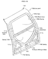
- FIG. 13 is a perspective view of an inner panel reinforced by a V-shaped stiffening rib frame which is used for another embodiment of the present invention.
- an upper portion of the frame 104b of the inner panel 102b is the same with the frame 104a of the inner panel 102a in FIG. 9.
- a V-shaped stiffening rib frame 115 is disposed from both bottom corners of the window frame 105b formed on the frame 104b to a locking device fixing portion 110, and openings 116a, 116b are formed on both sides of the V-shaped stiffening rib frame 115.
- a hatchback door structure which uses the inner panel 102b shown in FIG. 13
- a press formability of the frame 104b is excellent due to utilization of a discrete lateral beam 106b. Therefore, the inner panel 102b reinforced by the V-shaped stiffening rib frame 115, which has higher louvered-walls 111b, has a satisfactory rigidity.
- a hatchback door structure using the inner panel 102b shown in FIG. 13 has all advantages of the hatchback door structure 101a described above.
- the hatchback door structure is effective for the weight saving of the structure due to the openings 116a, 116b.
- a hatchback door structure for vehicles which includes an inner panel arranged on an inner side of a vehicle; and an outer panel arranged on an outer side of the vehicle, wherein the inner panel includes a frame which has a shape outlining an outer shape of the hatchback door, and a pair of stiffening ribs which is integrally formed with the frame and extends approximately in a V-shape to both side portions of the frame from a bottom side of the frame.
- the inner panel is integrally formed by press-forming and includes a discrete lateral beam which is fixed and extends between jointing portions of the side portions of the frame and stiffening ribs, wherein, the discrete lateral beam is formed by press-forming, and a window frame on which a window glass is fixed is formed in an upper portion of the frame.
Landscapes
- Engineering & Computer Science (AREA)
- Mechanical Engineering (AREA)
- Body Structure For Vehicles (AREA)
- Window Of Vehicle (AREA)
Abstract
Description
- This application claims the foreign priority benefit under Title 35, United States Code, §119(a)-(d) of
Japanese Patent Application Numbers 2006-017032, filed on January 26, 2006 2006-064021, filed on March 9, 2006 - The present invention relates to a hatchback door structure for vehicles, which is light and rigid.
- A hatchback door structure has been known, which includes an inner panel in which a lateral beam is integrally formed with a frame which has a shape outlining an outer shape of the hatchback door so that the lateral beam divides the frame into an upper portion and a lower portion (for example, refer to paragraphs 0010 to 0015 and FIG. 1 of
Japanese Patent Laid-Open Publication Kokai No. H08-258568 hatch back door 201 of a vehicle V includes aninner panel 206 comprising aframe 209 and alateral beam 218. Awindow glass 207 is fixed in anopening 212a zoned by theframe 209 and thelateral beam 218 on an upper side of thelateral beam 218. In anopening 212b zoned by theframe 209 and thelateral beam 218 on a lower side of thelateral beam 218, a pair ofjoint reinforcements 200a is disposed. A lower end ^vf eachreinforcement 200a is welded on theframe 209 through alock reinforcement 200b which is fixed at a center of a bottom side of theframe 209. The pair of thejoint reinforcements 200a extends in a V-shape to each upper corner of the opening 212b. An upper end of thejoint reinforcement 200a is welded on theframe 209 and thelateral beam 218 through acorresponding corner reinforcement 200c which is fixed on a corresponding upper corner of the opening 212b. - In the
hatchback door structure 201, a rigidity of theinner panel 206 is increased by disposing the pair ofjoint reinforcements 200a in the opening 212b. - Generally, a hatchback door fitted up on a tailgate in a rear part of a vehicle is jointed to the vehicle with a hinge structure. An opening-closing motion of the hatchback door is performed by rotating the door about the hinge located at the upper end of the door. These types of hatchback doors are required to increase the rigidity for improving collision strength and for avoiding muffled sounds when a vehicle runs a punishing road. On the other hand, the hatchback door must be light for reducing fuel consumption of a vehicle and improving easiness of the opening-closing motion of the door. Because of the above reasons, most of conventional hatchback doors for vehicles have a structure combining a thin outer panel and a thin inner panel which has openings, and the structure is reinforced by utilizing shapes of the both panels.
- FIG. 15 is a perspective view showing an example of an inner panel which configures a conventional hatchback door structure. In an
inner panel 302c of the example, aframe 304c which outlines an outer shape of the hatchback door is formed. In an upper portion of theframe 304c, awindow frame 305c is formed and an opening 308c in which a window glass is to be set is disposed. An opening 309c is disposed in a lower portion of theinner panel 302c for weight saving. In theinner panel 302c, alateral beam 306c which separates the twoopenings 308c, 309c is formed. Thelateral beam 306c is integrally formed with theframe 304c by press-forming. Thelateral beam 306c is a component for increasing a rigidity of theinner panel 302c against a lateral bending. Examples disclosed inJapanese Patent No. 3013921 Japanese Unexamined Patent Publication Kohyo No. 11-514613 - However, in the
hatchback door structure 201 in FIG. 14, the discretejoint reinforcements 200a are welded on theframe 209 and thelateral beam 218, while requiring other members such as thelock reinforcement 200b and thecorner reinforcements 200c for welding thejoint reinforcements 200a. Therefore, the manufacturing cost becomes high, and at the same time, a weight of thehatchback door structure 201 increases. Further, a working process increases due to necessity of the welding. - In addition, in FIG. 15, since the
lateral beam 306c for reinforcing theinner panel 302c, which is used for a conventional hatchback door structure, is integrally formed with theframe 304c when theinner panel 302c is formed by press-forming, there are following problems. - The first problem is as follows. When the
lateral beam 306c is integrally formed as in theinner panel 302c shown in FIG. 15, a formation of cut-and-turned-up walls (hereinafter, referred to as louvered-walls) 311c with a sufficient height formed on peripheries of theopenings 308c, 309c of theinner panel 302c is difficult due to a limitation in press formability, unless a highly-ductile material is used for the panel. Therefore, an increase of the rigidity of theinner panel 302c is limited. - The second is as follows.
Corners 312c, where thelateral beam 306c and theframe 304c of theinner panel 302c are jointed, are required to have a radius R larger than a predetermined value. As a result, a size of the opening 308c for the rear glass window should be made smaller, which narrows a rearward visibility of a vehicle. - The third is as follows. Improvement of the rigidity of the
inner panel 302c against bending in a tangential direction relative to a circular path formed by the rotation circle of the hatchback door is difficult. When a hatchback door is closed, the hatchback door receives a force in the tangential direction. Therefore, if the louvered-walls 311c of thelateral beam 306c are formed in parallel with the tangential direction, the vibrations of the hatchback door are effectively suppressed. However, since an inclination of the louvered-walls 311c of thelateral beam 306c is determined by a direction of the press-forming of theinner panel 302c, the louvered-walls 311c may not be inclined in the effective direction for suppressing the vibrations of the hatchback door when the door is closed. - The fourth is as follows. Since the
lateral beam 306c is integrally formed with theinner panel 302c, a panel thickness of thelateral beam 306c can not be made difficult from that of theinner panel 302c. For example, changes in design to thin the panel thickness of thelateral beam 306c for the weight saving thinner than that of theframe 304c can not be performed. - It is, therefore, desired to provide a hatchback door structure for vehicles, which is light and capable of increasing a rigidity of the hatchback door structure, as well as capable of reducing a manufacturing process and cost.
- It is also desired to provide a hatchback door structure for vehicles, which can improve a rearward visibility of a vehicle.
- According to a first aspect of the present invention, there is provided a hatchback door structure for vehicles which comprises: an inner panel which is arranged on an inner side of a vehicle; and an outer panel which is arranged on an outer side of the vehicle, wherein the inner panel comprises a frame which has a shape outlining an outer shape of the hatchback door, and a pair of stiffening ribs which is integrally formed with the frame and extends approximately in a V-shape to both side portions of the frame from a bottom side of the frame.
- In the hatchback door structure, the inner panel is formed so that the pair of stiffening ribs extends approximately in a V-shape from the bottom side to the both side portions of the frame which has the shape outlining the outer shape of the hatchback door. That is, in the hatchback door structure, by securing an opening as large as possible on the inner panel due to utilization of the frame and stiffening ribs, the weight saving can be achieved, as well as increase in the rigidity.
- In addition, in the hatchback back door structure, since the frame and stiffening ribs are integrally formed, a plurality of reinforcements become unnecessary in contrast with the conventional hatchback door (for example, refer to
Japanese Patent Laid-Open Publication No. H08-258568 - Further, in the hatchback back door structure, since the plurality of reinforcements become unnecessary in contrast with the conventional hatchback door (for example, refer to
Japanese Patent Laid-Open Publication No. 08-258568 - A smoothly continuous surface portion may preferably but not necessarily be formed at a connection part of a side portion of the frame and stiffening rib.
- In the hatchback door structure, since there is not a bended portion where stresses tend to be concentrated, that is, since the smooth and continuous surface portion is formed at a connection part of the side portion of the frame and the stiffening rib, the rigidity can be further increased.
- The pair of the stiffening ribs may preferably but not necessarily extend approximately in a V-shape from a locking device fixing portion which is formed on the bottom part of the frame to each of the couple of side portions of the frame, the locking device fixing portion being configured for fixing a locking device.
- In the hatchback door structure, since the stiffening ribs extend approximately in a V-shape from the locking device fixing portion, the rigidity is further increased.
- The inner panel may preferably but not necessarily have louvered-walls which are integrally formed with the inner panel, protrude outward to an outer panel side and jointed to the outer panel.
- In the hatchback door structure, since the louvered-walls formed in the inner panel are jointed to the outer panel, the rigidity is further increased. In addition, in the hatchback door structure, since the louvered-walls are formed by cutting and turning up the panel when they are integrally formed with the inner panel, the louvered-walls can be formed easily at desired positions and with optimal shapes.
- On an upper side of the stiffening ribs, a first opening may preferably but not necessarily be defined by the stiffening ribs and the frame, on a lower side of one of the stiffening ribs, a second opening be defined by the one of the stiffening ribs and the frame, and on a lower side of the other stiffening rib, a third opening be defined by the other stiffening rib and the frame.
- In the hatchback door structure, since the first opening, the second opening, and the third opening are formed on the inner panel, openings can be formed as large as possible to cover broader area of the inner panel. As a result, the hatchback door structure can achieve the weight saving, as well as improvement of the rigidity.
- The inner panel further may preferably but not necessarily comprise a lateral beam which extends between jointing portions of the side portions of the frame and stiffening ribs, and is integrally formed with the inner panel by press-forming.
- In the hatchback door structure, since the lateral beam is formed to extend between the jointing portions of the side portions of the frame and the stiffening ribs, the rigidity is further increased. In addition, since the lateral beam is integrally formed with the frame and the stiffening ribs, a manufacturing process of the hatchback door structure (inner panel) can be simplified.
- The inner panel may preferably but not necessarily be integrally formed by press-forming, and further comprise a discrete lateral beam which extends between jointing portions of the side portions of the frame and stiffening ribs.
- In the hatchback door structure, by forming the discrete lateral beam which is different from the frame and the stiffening ribs, the press-forming of the inner panel can be performed easily and a flexibility in the press-forming can be increased. Accordingly, a larger opening can be secured in the inner panel.
- The discrete lateral beam may preferably but not necessarily be formed in a circular arc so that the lateral beam protrudes in convex to an outer side of a vehicle, and a size of a cross section of the lateral beam gradually becomes smaller from a center to both ends of the lateral beam.
- In the hatchback door structure, the discrete lateral beam is formed in a circular arc so that the lateral beam protrudes in convex to an outer side of a vehicle, and curves along an outer side of the hatchback door. If a heavy object such as a motor of a wiper is fixed at a center portion of the lateral beam, a large stress is generated at the center portion. In the hatchback door structure, even if the size of the cross section of the center portion is increased for supporting the heavy object with the center portion of the lateral beam, the weight saving of the lateral beam can be achieved, because the size of the cross section of the lateral beam gradually becomes smaller from the center to both ends of the lateral beam.
- The discrete lateral beam may preferably but not necessarily be arranged so that a protruded direction of the lateral beam which is approximately perpendicular to an extending direction of the lateral beam is directed along an opening-closing direction of the hatchback door.
- In the hatchback door structure, the lateral beam has a sufficient rigidity against a stress applied to the lateral beam, especially, when closing the hatchback door.
- Each fixing portion of the discrete lateral beam on each jointing portion may preferably but not necessarily be formed so that the each fixing portion is arranged on a same plane defined in a vehicle width direction.
- In the hatchback door structure, since a stress applied to the lateral beam, especially when closing the hatchback door, is uniformly transferred to each of the fixing portion, a load on the fixing portion of the lateral beam can be uniformly dispersed.
- In addition, in the hatchback door structure, since the lateral beam is fixed on the same plane, a positioning of the lateral beam relative to the jointing portion becomes easy, thereby resulting in improvement of workability for fixing the lateral beam.
- The discrete lateral beam may preferably but not necessarily be formed by press-forming, and a window frame on which a window glass is fixed be formed in an upper portion of the frame.
- In the hatchback door structure, the inner panel and the lateral beam to be jointed to the inner panel can be formed independently. Therefore, each of the members (inner panel and lateral beam) can be formed in an optimal shape for increasing the rigidity of the hatchback door structure.
- The discrete lateral beam and the inner panel can be formed with different press directions to each other.
- In the hatchback door structure, flexibility in the press-forming for the inner panel and lateral beam can be increased.
- The discrete lateral beam may preferably but not necessarily be fixed at approximately right angle against the frame of the inner panel at both bottom corners of the window frame.
- In the hatchback door structure, an area of the glass window at the bottom corners can be enlarged. As a result, a visibility in the bottom corners of the glass window can be improved.
- Structures of the inner panel and the discrete lateral beam may preferably but not necessarily have different cross sectional widths to each other in an inside-outside direction of the hatchback door.
- In the hatchback door structure, regardless of a press-formability of the lateral beam, the structures of the frame of the inner panel can be designed thicker in the inside-outside direction of the hatchback door. As a result, the rigidity of the hatchback door structure can be increased.
- The inner panel and the discrete lateral beam may preferably but not necessarily have different panel thicknesses to each other.
- In the hatchback door structure, the weight saving of the hatchback door structure can be achieved by thinning the panel thickness of the lateral beam.
- A material of the inner panel and a material of the discrete lateral beam may preferably but not necessarily be different to each other.
- In the hatchback door structure, the weight saving of the hatchback door structure can be achieved by forming the lateral beam with, for example, aluminum alloy.
- A hatchback door structure for vehicles according to the present invention can achieve the weight saving, while maintaining a sufficient rigidity. Further, the working process and manufacturing cost of the hatchback door structure can be reduced.
- In addition, the press-formability of the inner panel can be improved and the degree of freedom of the inner panel shape can be increased without using a highly-ductile panel material. As a result, the rigidity of the inner panel can be further increased. In addition, by enlarging the opening for the rear glass window compared with the conventional one, a rearward visibility of a vehicle can be widened. In addition, the direction of the press-forming of the discrete lateral beam can be optimized for increasing the rigidity of the hatchback door which is necessary for suppressing the vibrations of the hatchback door at closing the door. Further, a panel thickness of the discrete lateral beam can be changed for, for example, the weight saving.
-
- FIG. 1 is a partial perspective view of a vehicle to which a hatchback door structure according to a first embodiment of the present invention is applied;
- FIG. 2 is a perspective view showing an inner panel, seen from outside a vehicle, which configures a hatchback door structure according to the first embodiment;
- FIG. 3 is a partial perspective view showing a frame of an inner panel around a side and stiffening rib portions seen from inside a vehicle, that is, a portion indicated by an arrow C in FIG. 2;
- FIG. 4 is a perspective view showing an inner panel, seen from outside a vehicle, which configures a hatchback door structure according to a second embodiment of the present invention;
- FIG. 5 is a cross sectional view taken along a line X-X of FIG. 4;
- FIG. 6 is a side view of an inner panel according to the second embodiment;
- FIG. 7 is a perspective view of an inner panel, seen from outside a vehicle, which configures a hatchback door structure according to another embodiment of the present invention;
- FIG. 8 is a schematic view of a vehicle, seen from backward of the vehicle, to which a hatchback door structure according to a third embodiment of the present invention is fitted up;
- FIG. 9 is a perspective view of an inner panel which is used for a hatchback door structure according to the third embodiment;
- FIG. 10A is a perspective view of a discrete lateral beam according to the third embodiment;
- FIG. 10B is a cross sectional view of the discrete lateral beam according to the third embodiment, taken along a line N-N line at a center portion;
- FIG. 11 is a side view of an inner panel, seen from a A direction indicated by an arrow A in FIG. 9, which is used for the third embodiment;
- FIG. 12A is an enlarged view of a portion B in FIG. 9 on which a lateral beam of an inner panel according to the third embodiment is welded;
- FIG. 12B is an enlarged view of a portion P in FIG. 15 on which a lateral beam of an inner panel according to a conventional example is welded;
- FIG. 13 is a perspective view of an inner panel reinforced by a V-shaped stiffening rib which is used for another embodiment of the present invention;
- FIG. 14 is a schematic illustration of a vehicle, seen from backward of the vehicle, for explaining a configuration of a conventional hatchback door structure; and
- FIG. 15 is a perspective view showing an example of an inner panel which configures a conventional hatchback door structure.
- Next, a hatchback door structure for vehicles according to a first embodiment will be explained in detail by referring to figures, as needed. FIG. 1 is a partial perspective view of a vehicle to which a hatchback door structure according to the first embodiment is applied. FIG. 2 is a perspective view showing an inner panel, seen from outside a vehicle, which configures a hatchback door structure according to the embodiment. FIG. 3 is a partial perspective view showing a frame of an inner panel around a side and stiffening rib portions seen from inside a vehicle, that is, a portion indicated by an arrow C in FIG. 2.
- As shown in FIG. 1, a
hatchback door structure 1a is applied to ahatchback door 2 for opening and closing a tailgate opening 3 of a vehicle V. Thehatchback door 2 has a flip-up structure which rotates about hinges 4, 4 by jointing an upper periphery of thehatchback door 2 and an upper periphery of the tailgate opening 3 with a pair of thehinges hatchback door 2, a locking device (not shown) is disposed for locking thehatchback door 2 to a vehicle body at a closing position of the door. - The
hatchback door structure 1a includes anouter panel 5 which is arranged on an outer side of thehatchback door 2 and forms an outer side surface of the vehicle V, and aninner panel 6a arranged on an inner side of theouter panel 5. Thehatchback door 1a further includes awindow 7 to be completed by fitting a glass in an upper portion of thehatchback door 2, and awiper 8 arranged in a lower portion of thewindow 7. - As shown in FIG. 1, the
inner panel 6a includes aframe 9 which outlines an outer shape of thehatchback door 2, and a pair of stiffeningribs frame 9. - As shown in FIG. 2, the
frame 9 according to the embodiment is formed by press-forming of a metal plate, and, in plane view, has an outer contour in approximately a rectangular shape, as well as an opening in approximately a rectangular shape inside theframe 9. - In addition, a locking
device fixing portion 11 is disposed at a bottom center of theframe 9 for fixing the locking device (not shown). - As shown in FIG. 2, the stiffening
ribs 10a, lOb extend in approximately a V-shape from the bottom of theframe 9, specifically extend from the lockingdevice fixing portion 11 to both sides of theframe 9. Meanwhile, in the embodiment, the both sides of theframe 9 to which thestiffening ribs - Accordingly, by partitioning an opening formed inside the
frame 9 with the stiffeningribs first opening 12 is defined by upper sides of thestiffening ribs frame 9, asecond opening 13 is defined by a lower side of onestiffening rib 10a and theframe 9, and athird opening 14 is defined by a lower side of another stiffeningrib 10b and theframe 9. Meanwhile, thefirst opening 12 according to the embodiment has a pentagonal shape and thesecond opening 13 andthird opening 14 are triangle, in plane view. - As shown in FIG. 2, the
inner panel 6a includes a plurality of cut-and-turned-up walls (hereinafter, referred to as louvered-walls) 15 on peripheries of thefirst opening 12, thesecond opening 13, and thethird opening 14. The louvered-walls 15 are formed to turn up in a direction of the outer panel 5 (refer to FIG. 1), that is, in a direction D (refer to FIG. 2) toward outside a vehicle. In thefirst opening 12, the louvered-walls 15 are formed to turn up from theframe 9 and each stiffeningrib first opening 12. The louvered-walls 15 of thesecond opening 13 andthird opening 14 are formed to turn up from theframe 9. Ends of the louvered-walls 15 are jointed to the outer panel 5 (refer to FIG. 1). - In addition, as shown in FIG.3, the
inner panel 6a has acurved surface portion 16 which is smoothly and continuously formed at a connection part of a side portion of theframe 9 and thestiffening rib 10a. Thecurved surface portion 16 corresponds to a "surface portion". Further, another smoothly continuous curved surface portion (not shown) is also formed at a connection part of a side portion of theframe 9 and thestiffening rib 10b shown in FIG. 2 in the same manner as thecurved surface portion 16 in FIG. 3. - Meanwhile, the
inner panel 6a of thehatchback door structure 1a according to the first embodiment is also used for ahatchback door structure 1b (refer to FIG. 4) according to a second embodiment, which will be described later. Theinner panel 6a has a lateralbeam fixing portion 19 on which a lateral beam 18(refer to FIG. 4), which will be described later, is fixed. As shown in FIG. 3, the lateralbeam fixing portion 19 is formed on ajointing portion 17 of theframe 9 and the stiffening rib 10, and specifically, it is formed to rise from a periphery on a side of the direction D (outer side of a vehicle) of thecurved surface portion 16 to thefirst opening 12. - Next, effects and advantages of the
hatchback door structure 1a according to the embodiment will be explained. - As described above, in the
hatchback door structure 1a, since theinner panel 6a is formed so that the pair of thestiffening ribs frame 9 which outlines the outer shape of thehatchback door 2, thefirst opening 12, thesecond opening 13, and thethird opening 14 are formed in theinner panel 6a (refer to FIG. 1). That is, in thehatchback door structure 1a, a weight saving as well as increase in the rigidity is achieved by disposing an opening as large as possible on theinner panel 6a due to utilization of theframe 9 and thestiffening ribs 10a, lOb. - In addition, in the
hatchback door structure 1a, since theframe 9 and thestiffening ribs 10a, lOb are integrally formed by, for example, press-forming, a plurality of reinforcements become unnecessary in contrast with the conventional hatchback door 201 (refer to FIG. 14), thereby resulting in the weight reduction and manufacturing cost saving. - In addition, in the
hatchback door structure 1a, since a plurality of the reinforcements are unnecessary in contrast with the conventional hatchback door 201 (refer to FIG. 14), a welding process becomes unnecessary, thereby resulting in reduction of the manufacturing process. - Further, in the
hatchback door structure 1a, since there is not a bended portion where stresses tend to be converged and the curved surface portion 16 (refer to FIG. 3) is formed smoothly and continuously, the rigidity can be further increased. - Furthermore, in the
hatchback door structure 1a, since the louvered-walls 15 formed on the peripheries of thefirst opening 12, thesecond opening 13, and thethird opening 14 are jointed to the outer panel 5 (refer to FIG. 1), the rigidity can be further improved, while ensuring the weight saving by disposing an opening as large as possible on theinner panel 6a. In addition, since the louvered-walls 15 are turned up on the peripheries of thefirst opening 12, thesecond opening 13, and thethird opening 14 in thehatchback door structure 1a, the louvered-walls 15 can be formed simultaneously with the formation of thefirst opening 12, thesecond opening 13, and thethird opening 14, and can be formed easily in desired positions with optimal shapes. - Next, a hatchback door structure for vehicles according to a second embodiment of the present invention will be explained in detail by referring to figures, as needed. FIG. 4 is a perspective view showing an inner panel, seen from outside a vehicle, which configures a hatchback door structure according to a second embodiment of the present invention. FIG. 5 is a cross sectional view taken along a line X-X of FIG. 4. FIG. 6 is a side view of an inner panel according to the second embodiment. Meanwhile, FIG. 6 shows a state in which hinges are fixed on an inner panel. A vehicle to which the inner panel is fitted up is shown with a dashed-two dotted line. In the hatchback door structure according to the second embodiment, a configuration of the structure is identical to that of the first embodiment except a presence of a lateral beam on the inner panel. Therefore, the inner panel will be mainly explained. A component identical to that of the first embodiment is labeled a same symbol, and the detailed explanation will be omitted.
- As shown in FIG. 4, a
lateral beam 18 is fixed on theinner panel 6a so that thelateral beam 18 extends between thejointing portions frame 9 and thestiffening ribs lateral beam 18 is formed in a circular arch which is convex in a direction D directed to outside a vehicle, that is, formed in a curved shape outlining an outer surface (outer surface of theouter panel 5, refer to FIG. 1) of the hatchback door 2 (refer to FIG. 2). Thelateral beam 18 is a discrete member which is different from theframe 9 and thestiffening ribs lateral beam 18 is fixed on the lateral beam fixing portions 19 (refer to FIG. 3) by, for example, spot welding. In this case, thelateral beam 18 is fixed on the lateralbeam fixing portions 19 from outside a vehicle. Meanwhile, thelateral beam 18 may also be fixed from inside a vehicle. As shown in FIG. 5, in thelateral beam 18 according to the embodiment, a size of a cross section of thelateral beam 18 gradually becomes larger from both ends to a center portion. That is, a thickness of thelateral beam 18 in a direction protruded outside a vehicle gradually becomes thicker as a position of the cross section approaches the center portion from the both ends (gradually becomes thinner from the center portion to the both ends). A heavy object such as a motor (not shown) of thewiper 8 may be mounted on the center portion of thelateral beam 18. Each of the lateralbeam fixing portions jointing portions - In addition, as shown in FIG. 6, the
lateral beam 18 is arranged so that a protruding direction H, which is approximately perpendicular to an extending direction G (refer to FIG. 5) of thelateral beam 18, is directed along an opening-closing direction J of thehatchback door 2. - Next, effects and advantages of the
hatchback door structure 1b according to the embodiment will be explained. In thehatchback door structure 1b, the press-forming of theinner panel 6a can be easily performed by forming thelateral beam 18 as a discrete member which is different from theframe 9 and thestiffening ribs - In the
hatchback door structure 1b, thelateral beam 18 is curved in a circular arch, and the size of the cross section gradually increases from the both ends to the center portion (see FIG. 5). Therefore, even if a large stress is applied to the center portion of thelateral beam 18 by fixing a heavy object such as a motor (not shown) of thewiper 8, thelateral beam 18 can support the stress due to the rigidity. In other words, since the size of the cross section of thelateral beam 18 gradually decreases as a position of the cross section approaches the both ends from the center portion, the weight saving of thelateral beam 18 also can be achieved. - In addition, in the
hatchback door structure 1b, since thelateral beam 18 is arranged so that the protruding direction H (refer to FIG.6), which is approximately perpendicular to the extending direction G of thelateral beam 18, is directed along the opening-closing direction J of thehatchback door 2, thelateral beam 18 can sufficiently support a load applied thereon, especially when thehatchback door 2 is closed. - Further, in the
hatchback door structure 1b, each of the lateralbeam fixing portions 19, 19 (refer to FIG. 5) of thelateral beam 18 is disposed on the same plane F which is defined in the width direction of a vehicle. Therefore, thelateral beam 18 can equally transfer a load applied thereon to each of the lateralbeam fixing portions hatchback door 2 is closed. As a result, the load applied to the lateralbeam fixing portions hatchback door structure 1b, since thelateral beam 18 is fixed on the same plane F, the positioning of thelateral beam 18 relative to thejointing portion 17 becomes easier, thereby resulting in improvement of fixing workability of thelateral beam 18. - Meanwhile, the present invention is not limited to the aforementioned embodiments, but can be embodied in various modifications. In the first and second embodiments, the louvered-
walls 15 of theinner panel 6a are formed on the peripheries of all openings: thefirst opening 12, thesecond opening 13, and thethird opening 14. However, the louvered-walls 15 may be formed on the peripheries of at least one of these openings. - In addition, in the second embodiment, the
lateral beam 18 is fixed on theinner panel 6a as a discrete member. However, the present invention is not limited to this. Here, FIG. 7 is a perspective view of an inner panel, seen from outside a vehicle, which configures a hatchback door structure according to another embodiment of the present invention. - As shown in FIG. 7, in an
inner panel 6b which configures ahatchback door structure 1c, thelateral beam 18 extending between thejointing portions inner panel 6b by press-forming. - In the
hatchback door structure 1c, since thelateral beam 18 is integrally formed with theframe 9 and the stiffening ribs 10 (10a, 10b), the manufacturing process of thehatchback door structure 1c (inner panel 6b) can be simplified, and at the same time, the rigidity can be increased. - In addition, in the aforementioned embodiments, the stiffening
ribs ribs - Next, a hatchback door structure for vehicles according to a third embodiment of the present invention will be explained in detail by referring to figures, as needed.
- FIG. 8 is a schematic view of a vehicle, seen from backward of the vehicle, to which a hatchback door structure according to the third embodiment of the present invention is fitted up. A
hatchback door structure 101a according to the third embodiment is configured with aninner panel 102a and anouter panel 103. Thehatchback door structure 101a is fitted up to a vehicle V with hinges 114. Theinner panel 102a and theouter panel 103 are assembled by a hemming process or spot-welding and the like. In theinner panel 102a, aframe 104a which outlines thehatchback door structure 101a along its outer shape is formed. In theframe 104a, awindow frame 105a on which aglass window 107 is fixed is formed, and alateral beam 106a is fixed on theframe 104a. At a bottom of theframe 104a, a lockingdevice fixing portion 110 is formed. - FIG. 9 is a perspective view of an inner panel which is used for a hatchback door structure according to the third embodiment. In an upper portion of the
frame 104a configuring theinner panel 102a, thewindow frame 105a is formed. Theframe 104a is formed by press-forming. On a pair ofwelding portions window frame 105a, which are located at a bottom of thewindow frame 105a, adiscrete lateral beam 106a is fixed from outside a vehicle by spot welding. Therefore, thelateral beam 106a is fixed between the pair of thewelding portions lateral beam 106a is fixed from outside a vehicle so that strength of the hatchback door against an impact at closing the hatchback door is increased. However, thelateral beam 106a may be fixed on thewelding portions window frame 105a from inside a vehicle. - On an upper side of the
lateral beam 106a, anopening 108a in which a glass window is fixed is disposed. In addition, on a lower side of thelateral beam 106a, anopening 109a is disposed. On peripheries of theseopenings walls 111a have effects to increase a rigidity of theinner panel 102a against a bending. - FIG. 10A is a perspective view of a
discrete lateral beam 106a which is used for the third embodiment. FIG. 10B is a cross sectional view of thelateral beam 106a used for the embodiment, taken along a line N-N at the center portion of thelateral beam 106a. Thelateral beam 106a is a member formed by press-forming as a discrete member which is different from theframe 104a of theinner panel 102a (refer to FIG. 8 and FIG. 9). Thelateral beam 106a has a pair ofwelding portions welding portions window frame 105a which is formed on theframe 104a which configures theinner panel 102a (refer to FIG. 9). - A portion between the pair of
welding portions beam portion 121. In thebeam portion 121, a pair of louvered-walls 122 is formed. The louvered-walls 122 are disposed for increasing the rigidity of theinner panel 102a against a lateral bending. - The louvered-
walls 122 become higher from each end of thebeam portion 121 to a center portion. The louvered-walls 122 have the maximum height L3 at a center of thebeam portion 121. Thus, thelateral beam 106a is formed in an arch in which a size of a cross section of thelateral beam 106a becomes maximum at the center and minimum at the both ends of thebeam portion 121. By forming thelateral beam 106a as described above, a bending stress applied to thelateral beam 106a becomes uniform within thelateral beam 106a. - In addition, since the
lateral beam 106a is formed as a discrete member different from theframe 104a, a level of freedom of the shape design becomes higher than that of theconventional lateral beam 306c (refer to FIG. 15). For example, it is easy to make the maximum height L3 of the louvered-walls 122 of thelateral beam 106a higher than that of the louvered-walls 311c of theconventional lateral beam 306c. In addition, if the louvered-walls 122 are made higher, a rigidity of thelateral beam 106a against a bending can be maintained, even if thelateral beam 106a is formed using a thinner panel material than that of theframe 104a by press-forming. - Further, the
lateral beam 106a has a superior press formability since it is formed as a discrete member by press-forming. Therefore, a formation of holes for weight saving on a bottom 124 and an uppercurved portion 125 of thebeam portion 121 can be performed relatively easily. A hole for fixing, for example, a motor of a wiper may be formed on the uppercurved portion 125 of thelateral beam 106a in some case, and any portion of the uppercurved portion 125 can be used to form the hole because of the excellent press formability. For example, for a motor of a wiper or the like fixed on thelateral beam 106a, a fixing weld-nut or the like can be welded in advance on the uppercurved portion 125 of thelateral beam 106a. - In the
lateral beam 106a of theinner panel 102a which is used for thehatchback door structure 101a (refer to FIG. 8) according to the embodiment, when thelateral beam 106a is formed, a direction of press-forming (hereinafter, referred to as press direction) forms a constant angle α with a direction perpendicular to a surface of a pair of thewelding portions lateral beam 106a makes the angle α with a vertical direction to the surface of thewelding portions walls 122 which are formed by the press-forming are not perpendicular to the surface of the pair of thewelding portions hatchback door structure 101a including theinner panel 102a is fitted up on the vehicle V, thehatchback door structure 101a rotates about thehinges 114 which connect thehatchback door structure 101a to the vehicle V. The press direction is determined to form the angle α with the vertical direction of the surface of the pair of thewelding portions walls 122 become in parallel with a tangential direction of a rotation circle of the hatchback door. - FIG. 11 is a side view of an
inner panel 102a, seen from a direction of an arrow A in FIG. 9, to be used for the third embodiment. The angle α between the press direction of thelateral beam 106a shown in FIG. 10B and the vertical direction to the surface of the pair ofwelding portions welding portions lateral beam 106a and the center between the two hinges 114. Due to the above, the press direction of thelateral beam 106a is in parallel with the tangential direction of the rotation circle of the hatchback door about thehinges 114 of theinner panel 102a. - When the hatchback door is closed, the
hatchback door structure 101a (refer to FIG. 8) receives a force in the tangential direction of the rotation circle. As a result, vibrations are generated in thehatchback door structure 101a. However, as described above, the vibrations can be effectively suppressed due to the relatively high rigidity of the louvered-walls 122 which is obtained by making the press direction of thelateral beam 106a in parallel with the tangential direction of the rotation circle of thehatchback door structure 101a. - In a conventional
inner panel 302c shown in FIG. 15, since alateral beam 306c is integrally formed with aframe 304c, press directions of theframe 304c and thelateral beam 306c are always same. However, a press direction of thelateral beam 106a according to the embodiment is not matched with that of theinner panel 102a (refer to FIG. 11). In the present invention, since thelateral beam 106a is formed as a discrete member which is different from theinner panel 102a, a press direction of each member can be determined independently. - Since the
lateral beam 106a is a discrete member different from theframe 104a of theinner panel 102a, a panel thickness of thelateral beam 106a may be different from that of theframe 104a for the weight saving as described above. In addition, a material of thelateral beam 106a may be different from that of theframe 104a. - An explanation of
corner portions lateral beam 106a and thewindow frame 105a of theinner panel 102a are welded will be made by comparing withcorner portions inner panel 302c shown in FIG. 15. FIG. 12A is an enlarged view of a portion B in FIG. 9 in which a lateral beam of an inner panel according to the embodiment is welded to theframe 104a. FIG. 12B is an enlarged view of a portion P in FIG. 15 in which a lateral beam of an inner panel of a comparative example is integrally formed with aframe 304c. As shown in FIG. 12A, in theinner panel 102a according to the embodiment, thelateral beam 106a is welded on thewindow frame 105a at approximately right angle. On the other hand, in theinner panel 302c of the comparative example shown in FIG. 12B, since alateral beam 306c is integrally formed with awindow frame 305c, thecorner portions inner panel 302c becomes smaller than theopening 108a of theinner panel 102a according to the embodiment. - In the
inner panel 102a which is used for thehatchback door structure 101a according to the embodiment, since thelateral beam 106a is formed as a discrete member, a height L1 (refer to FIG. 12A and FIG. 9) of the louvered-walls 111a of theinner panel 102a can be determined independently of the maximum height L3 of the louvered-walls 122 (refer to FIG. 10B) of thelateral beam 106a. On the other hand, in the case of the comparative example (refer to FIG. 12B and FIG. 15), since thelateral beam 306c is integrally formed, there is a limitation on the press formability. As a result, a height L2 of the louvered-walls 311c of theframe 304c and thelateral beam 306c is limited by the press-forming, thereby resulting in a certain limited height Lc (not shown) or less. - In the
inner panel 102a, since thelateral beam 106a is formed as a discrete member different from theframe 104a, the press formability is superior to that of the conventionalinner panel 302c. Therefore, the height L1 of the louvered-walls 111a can easily be made higher than the limited height Lc of the louvered-walls 311c. Therefore, by increasing the height L1 of the louvered-walls 111a as needed, that is, by increasing a cross sectional width in an inside-outside direction of the hatchback door structure 101a, the rigidity of theframe 104a which configures theinner panel 102a can be increased. - Next, effects and advantages of the
hatchback door structure 101a according to the embodiment will be explained based on the configuration of thehatchback door structure 101a. - In the
hatchback door structure 101a according to the embodiment, a press direction of thelateral beam 106a of theinner panel 102a can be determined independently from that of theinner panel 102a. As a result, as described above, by selecting the press direction of thelateral beam 106a, the vibrations of the hatchback door at closing the door can be suppressed effectively, compared with the conventional hatchback door. - In the
inner panel 102a to be used for thehatchback door structure 101a according to the embodiment, since thelateral beam 106a is fixed as a discrete member, the press formability of theinner panel 102a is improved, compared with the conventional example. As a result, the height of the louvered-walls 111a of theframe 104a of theinner panel 102a can be made higher than that of the louvered-walls 311c of the conventionalinner panel 302c. Accordingly, the rigidity of theinner panel 102a can be increased. - In the
inner panel 102a to be used for thehatchback door structure 101a according to the embodiment, as shown in FIG. 12A, thelateral beam 106a is fixed on thewindow frame 105a of theframe 104a at approximately right angle. As a result, a rearward visibility can be improved due to increase in theopening 108a for a glass window, compared with the conventional example in which thelateral beam 306c shown in FIG. 15 is integrally formed with thewindow frame 305c of theframe 304c. - In the
inner panel 102a to be used for thehatchback door structure 101a according to the embodiment, since thelateral beam 106a is formed as a discrete member different from theframe 104a (refer to FIG. 9), the rigidity of theinner panel 102a can be effectively increased by modifying a shape of thelateral beam 106a. In addition, by increasing or decreasing a plate thickness of thelateral beam 106a as needed, the weight saving or rigidity improvement of theinner panel 102a can be achieved. Further, a material of thelateral beam 106a can be different from that of theframe 104a. For example, aluminum alloy can be employed as a material of thelateral beam 106a for the weight saving. - In addition, since the
lateral beam 106a is formed as a discrete member different from theframe 104a, an amount of a panel material punched out by the press-forming from a window portion of theframe 104a becomes fairly large. Therefore, the panel material punched out by the press forming can be utilized for manufacturing other components. - In the
hatchback door structure 101a according to the embodiment, a small component such as a nut can be assembled in advance on thediscrete lateral beam 106a. For example, a weld-nut for fixing a motor of a wiper can be welded in advance on thelateral beam 106a. Through the above, a number of component to be welded on the panel can be reduced, thereby resulting in simplification of the welding process. - The present invention is not limited to the aforementioned embodiment. Modifications of each configuration requirement of the embodiment are possible without departing from the spirits of the present invention. For example, it is unnecessary that a press direction of the
lateral beam 106a in FIG. 11 is accurately in parallel with the tangential direction of the rotation circle of the hatch back door. Further, the following modification of theframe 104a of theinner panel 102a is also included in the present invention. - FIG. 13 is a perspective view of an inner panel reinforced by a V-shaped stiffening rib frame which is used for another embodiment of the present invention. In the embodiment, an upper portion of the
frame 104b of theinner panel 102b is the same with theframe 104a of theinner panel 102a in FIG. 9. However, a V-shapedstiffening rib frame 115 is disposed from both bottom corners of thewindow frame 105b formed on theframe 104b to a lockingdevice fixing portion 110, andopenings stiffening rib frame 115. - In a hatchback door structure which uses the
inner panel 102b shown in FIG. 13, a press formability of theframe 104b is excellent due to utilization of adiscrete lateral beam 106b. Therefore, theinner panel 102b reinforced by the V-shapedstiffening rib frame 115, which has higher louvered-walls 111b, has a satisfactory rigidity. Then, a hatchback door structure using theinner panel 102b shown in FIG. 13 has all advantages of thehatchback door structure 101a described above. In addition, the hatchback door structure is effective for the weight saving of the structure due to theopenings - A hatchback door structure for vehicles which includes an inner panel arranged on an inner side of a vehicle; and an outer panel arranged on an outer side of the vehicle, wherein the inner panel includes a frame which has a shape outlining an outer shape of the hatchback door, and a pair of stiffening ribs which is integrally formed with the frame and extends approximately in a V-shape to both side portions of the frame from a bottom side of the frame. Further, the inner panel is integrally formed by press-forming and includes a discrete lateral beam which is fixed and extends between jointing portions of the side portions of the frame and stiffening ribs, wherein, the discrete lateral beam is formed by press-forming, and a window frame on which a window glass is fixed is formed in an upper portion of the frame.
Claims (16)
- A hatchback door structure for vehicles, comprising:an inner panel which is arranged on an inner side of a vehicle; andan outer panel which is arranged on an outer side of the vehicle,wherein the inner panel comprises:a frame which has a shape outlining an outer shape of the hatchback door, anda pair of stiffening ribs which are integrally formed with the frame and extends approximately in a V-shape from a bottom part of the frame to each of a couple of side portions of the frame.
- The hatchback door structure for vehicles according to claim 1,
wherein a smoothly continuous surface portion is formed at a connection part between a side portion of the frame and the stiffening rib. - The hatchback door structure for vehicles according to claim 1,
wherein the pair of the stiffening ribs extends approximately in a V-shape from a locking device fixing portion which is formed on the bottom part of the frame to each of the couple of side portions of the frame, the locking device fixing portion being configured for fixing a locking device. - The hatchback door structure for vehicles according to claim 1,
wherein the inner panel has louvered-walls which are integrally formed with the inner panel, protrude outward to an outer panel side and jointed to the outer panel. - The hatchback door structure for vehicles according to claim 1,
wherein, on an upper side of the stiffening ribs, a first opening is defined by the stiffening ribs and the frame, on a lower side of one of the stiffening ribs, a second opening is defined by the one of the stiffening ribs and the frame, and on a lower side of the other stiffening rib, a third opening is defined by the other stiffening rib and the frame. - The hatchback door structure for vehicles according to claim 1,
wherein the inner panel further comprises a lateral beam which extends between jointing portions on each of which are jointed the side portion of the frame and stiffening rib, and is integrally formed with the inner panel by press-forming. - The hatchback door structure for vehicles according to claim 1,
wherein the inner panel is integrally formed by press-forming, and further comprises a discrete lateral beam which extends between jointing portions on each of which are jointed the side portion of the frame and stiffening rib. - The hatchback door structure for vehicles according to claim 7,
wherein the d-iscrete lateral beam is formed in a circular shape so that the lateral beam protrudes in convex to an outer side of a vehicle, and a size of a cross section of the lateral beam gradua-Ily becomes smaller from a center to each of a couple of ends of the lateral beam. - The hatchback door structure for vehicles according to any one of claims 7 and 8,
wherein the discrete lateral beam is arranged so that a protruded direction of the lateral beam which is more or less perpendicular to an extending direction of the lateral beam is directed along an opening-closing direction of the hatchback door. - The hatchback door structure for vehicles according to claim 7,
wherein each fixing portion of the discrete lateral beam on each jointing portion is formed so that the each fixing portion is arranged on an identical plane defined in a vehicle width direction. - A hatchback door structure for vehicles according to claim 7,
wherein, the discrete lateral beam is formed by press-forming, and a window frame on which a window glass attaches is formed in an upper portion of the frame. - The hatchback door structure for vehicles according to claim 11,
wherein the press-forming direction of the discrete lateral beam is different from the press-forming direction of the inner panel. - The hatchback door structure for vehicles according to any one of claims 11 and 12,
wherein the discrete lateral beam is fixed at approximately right angle against the frame of the inner panel at both bottom corners of the window frame. - The hatchback door structure for vehicles according to any one of claims 11 and 12,
wherein a cross sectional width of the inner panel is different from a cross sectional width of the discrete lateral beam in an inside-outside direction of the hatchback door. - The hatchback door structure for vehicles according to claim 11,
wherein a material of the inner panel is different from a material of the discrete lateral beam in thickness. - The hatchback door structure for vehicles according to any one of claims 11 and 12,
wherein a material of the inner panel is different from a material of the discrete lateral beam.
Applications Claiming Priority (2)
| Application Number | Priority Date | Filing Date | Title |
|---|---|---|---|
| JP2006017032A JP4221003B2 (en) | 2006-01-26 | 2006-01-26 | Vehicle rear door structure |
| JP2006064021A JP4388527B2 (en) | 2006-03-09 | 2006-03-09 | Vehicle rear door structure |
Publications (4)
| Publication Number | Publication Date |
|---|---|
| EP1813454A2 true EP1813454A2 (en) | 2007-08-01 |
| EP1813454A3 EP1813454A3 (en) | 2008-12-31 |
| EP1813454A9 EP1813454A9 (en) | 2009-03-18 |
| EP1813454B1 EP1813454B1 (en) | 2012-04-18 |
Family
ID=37963812
Family Applications (1)
| Application Number | Title | Priority Date | Filing Date |
|---|---|---|---|
| EP07001416A Ceased EP1813454B1 (en) | 2006-01-26 | 2007-01-23 | Hatchback door structure for vehicles |
Country Status (3)
| Country | Link |
|---|---|
| US (1) | US7537267B2 (en) |
| EP (1) | EP1813454B1 (en) |
| BR (1) | BRPI0700146B1 (en) |
Cited By (2)
| Publication number | Priority date | Publication date | Assignee | Title |
|---|---|---|---|---|
| CN101358506B (en) * | 2007-08-02 | 2012-07-04 | 通用汽车环球科技运作公司 | Vehicle door latch assembly |
| EP2740621A4 (en) * | 2011-08-01 | 2015-07-22 | Toyota Motor Co Ltd | REAR DOOR STRUCTURE FOR VEHICLE |
Families Citing this family (30)
| Publication number | Priority date | Publication date | Assignee | Title |
|---|---|---|---|---|
| JP4255947B2 (en) * | 2005-12-28 | 2009-04-22 | 本田技研工業株式会社 | Rear door structure and rear door assembly method |
| US7618083B2 (en) * | 2006-08-02 | 2009-11-17 | Honda Motor Co., Ltd. | Rear door structure for vehicle |
| JP4769229B2 (en) * | 2007-06-12 | 2011-09-07 | 本田技研工業株式会社 | Tailgate structure |
| US7681940B2 (en) * | 2007-08-13 | 2010-03-23 | Toyota Motor Engineering & Manufacturing North America, Inc. | Rear door assembly for a motor vehicle |
| KR20090044183A (en) * | 2007-10-31 | 2009-05-07 | 기아자동차주식회사 | Tailgate structure of the vehicle |
| US8403399B2 (en) * | 2008-05-30 | 2013-03-26 | Magna International Inc. | Composite liftgate system |
| JP5001907B2 (en) * | 2008-06-23 | 2012-08-15 | 本田技研工業株式会社 | Vehicle lock structure |
| JP5072768B2 (en) * | 2008-08-13 | 2012-11-14 | キャタピラー エス エー アール エル | Door panel |
| JP4712855B2 (en) * | 2008-10-23 | 2011-06-29 | 本田技研工業株式会社 | Rear door structure |
| JP4712854B2 (en) * | 2008-10-23 | 2011-06-29 | 本田技研工業株式会社 | Rear door structure |
| US7988217B2 (en) * | 2008-11-25 | 2011-08-02 | Toyota Motor Engineering & Manufacturing North America, Inc. | Hatchback door water management brackets |
| WO2010067405A1 (en) | 2008-12-12 | 2010-06-17 | ダイキョーニシカワ株式会社 | Vehicle window panel |
| EP2502770B1 (en) * | 2009-11-16 | 2014-02-12 | Toyota Jidosha Kabushiki Kaisha | Top-hinged door structure |
| JP5515778B2 (en) * | 2010-01-25 | 2014-06-11 | マツダ株式会社 | Vehicle back door structure |
| JP6049390B2 (en) * | 2012-10-17 | 2016-12-21 | ダイキョーニシカワ株式会社 | Vehicle back door |
| EP3055150B1 (en) * | 2013-10-07 | 2020-08-12 | SABIC Global Technologies B.V. | Closed section geometry, hollow shape, vehicle components |
| US8899658B1 (en) * | 2013-11-21 | 2014-12-02 | Ford Global Technologies, Llc | Liftgate hinge reinforcement |
| WO2015123312A1 (en) * | 2014-02-11 | 2015-08-20 | Magna International Inc. | Composite liftgate |
| CA2971368A1 (en) | 2014-12-25 | 2016-06-30 | Nippon Steel & Sumitomo Metal Corporation | Panel-shaped formed product and method for producing panel-shaped formed product |
| DE102016215093B4 (en) * | 2016-08-12 | 2021-01-07 | Bayerische Motoren Werke Aktiengesellschaft | Motor vehicle |
| US9834072B1 (en) * | 2016-09-21 | 2017-12-05 | Ford Global Technologies, Llc | Liftgate assembly for a vehicle |
| CN106671448A (en) * | 2017-01-20 | 2017-05-17 | 东风佛吉亚汽车外饰有限公司 | High-strength composite plastic inner stern door panel and method for molding thereof |
| JP2018144702A (en) * | 2017-03-07 | 2018-09-20 | スズキ株式会社 | Vehicle back door structure |
| CN107247838A (en) * | 2017-06-07 | 2017-10-13 | 奇瑞汽车股份有限公司 | The light weight method and device of automotive back door |
| US10744929B2 (en) * | 2018-07-18 | 2020-08-18 | Volkswagen Ag | Position tuning platform |
| CN111204198A (en) * | 2018-11-21 | 2020-05-29 | 上海汽车集团股份有限公司 | Car and tail-gate and inner panel of tail-gate thereof |
| CN109532434B (en) * | 2018-12-29 | 2023-12-12 | 威马智慧出行科技(上海)有限公司 | Electric back door inner plate |
| JP7800284B2 (en) * | 2022-04-25 | 2026-01-16 | マツダ株式会社 | Vehicle back door structure |
| US12168896B2 (en) | 2022-08-02 | 2024-12-17 | Toyota Motor Engineering & Manufacturing North America, Inc. | Backdoor assemblies for vehicles |
| CN116945871A (en) * | 2023-09-04 | 2023-10-27 | 宁波信泰机械有限公司 | Composite material tail gate inner plate cavity reinforcing structure |
Citations (1)
| Publication number | Priority date | Publication date | Assignee | Title |
|---|---|---|---|---|
| JPH08258568A (en) | 1995-03-24 | 1996-10-08 | Toyota Auto Body Co Ltd | Hatch back door reinforcing structure for vehicle |
Family Cites Families (12)
| Publication number | Priority date | Publication date | Assignee | Title |
|---|---|---|---|---|
| JPS62113615A (en) * | 1985-11-09 | 1987-05-25 | Daihatsu Motor Co Ltd | Rear door for automobile |
| US5314228A (en) * | 1993-03-16 | 1994-05-24 | Atlantic Research Corporation | Vehicle side impact intrusion barrier |
| DE19635873C2 (en) * | 1996-09-04 | 2001-05-17 | Schade Gmbh & Co Kg | Swiveling or sliding flap |
| JP3253864B2 (en) | 1996-10-02 | 2002-02-04 | 本田技研工業株式会社 | Vehicle tailgate reinforcement structure |
| US6053562A (en) * | 1997-10-21 | 2000-04-25 | Peregrine Incorporated | Door for a vehicle having a structural frame member and method of assembling same |
| JP4021074B2 (en) * | 1998-10-15 | 2007-12-12 | 本田技研工業株式会社 | Tailgate for hatchback vehicles |
| TW593005B (en) * | 2001-03-13 | 2004-06-21 | Kikuchi Press Industry Co Ltd | Door for vehicle and its manufacturing method |
| AT7550U1 (en) * | 2003-12-22 | 2005-05-25 | Engineering Ct Steyr Gmbh & Co | DOOR FOR THE DRIVER'S HOUSE OF A TRUCK |
| JP4255947B2 (en) * | 2005-12-28 | 2009-04-22 | 本田技研工業株式会社 | Rear door structure and rear door assembly method |
| JP4202360B2 (en) * | 2005-12-28 | 2008-12-24 | 本田技研工業株式会社 | Vehicle door structure |
| JP4482532B2 (en) * | 2006-03-09 | 2010-06-16 | 本田技研工業株式会社 | Vehicle rear door structure |
| US7618083B2 (en) * | 2006-08-02 | 2009-11-17 | Honda Motor Co., Ltd. | Rear door structure for vehicle |
-
2007
- 2007-01-23 EP EP07001416A patent/EP1813454B1/en not_active Ceased
- 2007-01-24 US US11/657,239 patent/US7537267B2/en active Active
- 2007-01-26 BR BRPI0700146-0A patent/BRPI0700146B1/en not_active IP Right Cessation
Patent Citations (1)
| Publication number | Priority date | Publication date | Assignee | Title |
|---|---|---|---|---|
| JPH08258568A (en) | 1995-03-24 | 1996-10-08 | Toyota Auto Body Co Ltd | Hatch back door reinforcing structure for vehicle |
Cited By (3)
| Publication number | Priority date | Publication date | Assignee | Title |
|---|---|---|---|---|
| CN101358506B (en) * | 2007-08-02 | 2012-07-04 | 通用汽车环球科技运作公司 | Vehicle door latch assembly |
| EP2740621A4 (en) * | 2011-08-01 | 2015-07-22 | Toyota Motor Co Ltd | REAR DOOR STRUCTURE FOR VEHICLE |
| US9162554B2 (en) | 2011-08-01 | 2015-10-20 | Toyota Jidosha Kabushiki Kaisha | Vehicle rear door structure |
Also Published As
| Publication number | Publication date |
|---|---|
| BRPI0700146A (en) | 2007-11-06 |
| US7537267B2 (en) | 2009-05-26 |
| US20070170751A1 (en) | 2007-07-26 |
| EP1813454A3 (en) | 2008-12-31 |
| EP1813454B1 (en) | 2012-04-18 |
| BRPI0700146B1 (en) | 2019-05-21 |
| EP1813454A9 (en) | 2009-03-18 |
Similar Documents
| Publication | Publication Date | Title |
|---|---|---|
| EP1813454B1 (en) | Hatchback door structure for vehicles | |
| US7591501B2 (en) | Hatchback door structure for vehicles | |
| CN101008307B (en) | Vehicle rear door structure | |
| EP1803597B1 (en) | Vehicle rear door and method of assembling same | |
| US8210596B2 (en) | Vehicle door with door beam | |
| US7300097B2 (en) | Door for vehicle | |
| US20060181107A1 (en) | Vehicle door | |
| JP4372743B2 (en) | Opening and closing structure of the vehicle | |
| EP2962880B1 (en) | Door structure for vehicle | |
| JP7095519B2 (en) | Front body structure of the vehicle | |
| US10988005B2 (en) | Vehicle door structure and method for manufacturing the same | |
| JP7743257B2 (en) | Hood inner panel and vehicle hood | |
| JP7685154B2 (en) | Vehicle back door structure | |
| JP6973579B2 (en) | Vehicle back door structure | |
| JP4388527B2 (en) | Vehicle rear door structure | |
| EP4197836B1 (en) | Vehicle door and vehicle | |
| JP2001063624A (en) | Superstructure of front pillar | |
| JP3789191B2 (en) | Front pillar lower structure | |
| JP7744319B2 (en) | Reinforcement structure for vehicle back door | |
| JP7601208B2 (en) | Vehicle tailgate structure | |
| CN114905941B (en) | Opening and closing parts | |
| JP6828326B2 (en) | Vehicle backdoor structure | |
| JP2003246278A (en) | Front pillar structure | |
| JP7135530B2 (en) | vehicle door structure | |
| JP2023070416A (en) | Vehicle body rear part structure |
Legal Events
| Date | Code | Title | Description |
|---|---|---|---|
| PUAI | Public reference made under article 153(3) epc to a published international application that has entered the european phase |
Free format text: ORIGINAL CODE: 0009012 |
|
| 17P | Request for examination filed |
Effective date: 20070123 |
|
| AK | Designated contracting states |
Kind code of ref document: A2 Designated state(s): AT BE BG CH CY CZ DE DK EE ES FI FR GB GR HU IE IS IT LI LT LU LV MC NL PL PT RO SE SI SK TR |
|
| AX | Request for extension of the european patent |
Extension state: AL BA HR MK RS |
|
| PUAL | Search report despatched |
Free format text: ORIGINAL CODE: 0009013 |
|
| AK | Designated contracting states |
Kind code of ref document: A3 Designated state(s): AT BE BG CH CY CZ DE DK EE ES FI FR GB GR HU IE IS IT LI LT LU LV MC NL PL PT RO SE SI SK TR |
|
| AX | Request for extension of the european patent |
Extension state: AL BA HR MK RS |
|
| RTI1 | Title (correction) |
Free format text: HATCHBACK DOOR STRUCTURE FOR VEHICLES |
|
| 17Q | First examination report despatched |
Effective date: 20090618 |
|
| AKX | Designation fees paid |
Designated state(s): DE GB |
|
| GRAP | Despatch of communication of intention to grant a patent |
Free format text: ORIGINAL CODE: EPIDOSNIGR1 |
|
| GRAS | Grant fee paid |
Free format text: ORIGINAL CODE: EPIDOSNIGR3 |
|
| GRAA | (expected) grant |
Free format text: ORIGINAL CODE: 0009210 |
|
| AK | Designated contracting states |
Kind code of ref document: B1 Designated state(s): DE GB |
|
| REG | Reference to a national code |
Ref country code: GB Ref legal event code: FG4D |
|
| REG | Reference to a national code |
Ref country code: DE Ref legal event code: R096 Ref document number: 602007022039 Country of ref document: DE Effective date: 20120614 |
|
| PLBE | No opposition filed within time limit |
Free format text: ORIGINAL CODE: 0009261 |
|
| STAA | Information on the status of an ep patent application or granted ep patent |
Free format text: STATUS: NO OPPOSITION FILED WITHIN TIME LIMIT |
|
| 26N | No opposition filed |
Effective date: 20130121 |
|
| REG | Reference to a national code |
Ref country code: DE Ref legal event code: R097 Ref document number: 602007022039 Country of ref document: DE Effective date: 20130121 |
|
| PGFP | Annual fee paid to national office [announced via postgrant information from national office to epo] |
Ref country code: GB Payment date: 20210113 Year of fee payment: 15 |
|
| PGFP | Annual fee paid to national office [announced via postgrant information from national office to epo] |
Ref country code: DE Payment date: 20211130 Year of fee payment: 16 |
|
| GBPC | Gb: european patent ceased through non-payment of renewal fee |
Effective date: 20220123 |
|
| PG25 | Lapsed in a contracting state [announced via postgrant information from national office to epo] |
Ref country code: GB Free format text: LAPSE BECAUSE OF NON-PAYMENT OF DUE FEES Effective date: 20220123 |
|
| REG | Reference to a national code |
Ref country code: DE Ref legal event code: R119 Ref document number: 602007022039 Country of ref document: DE |
|
| PG25 | Lapsed in a contracting state [announced via postgrant information from national office to epo] |
Ref country code: DE Free format text: LAPSE BECAUSE OF NON-PAYMENT OF DUE FEES Effective date: 20230801 |