EP1813307A1 - Phototherapy light with fresnel lens for infant care apparatus - Google Patents
Phototherapy light with fresnel lens for infant care apparatus Download PDFInfo
- Publication number
- EP1813307A1 EP1813307A1 EP07100083A EP07100083A EP1813307A1 EP 1813307 A1 EP1813307 A1 EP 1813307A1 EP 07100083 A EP07100083 A EP 07100083A EP 07100083 A EP07100083 A EP 07100083A EP 1813307 A1 EP1813307 A1 EP 1813307A1
- Authority
- EP
- European Patent Office
- Prior art keywords
- shade
- distal end
- light
- elongated member
- infant
- Prior art date
- Legal status (The legal status is an assumption and is not a legal conclusion. Google has not performed a legal analysis and makes no representation as to the accuracy of the status listed.)
- Withdrawn
Links
- 238000001126 phototherapy Methods 0.000 title claims abstract description 41
- 239000013307 optical fiber Substances 0.000 claims abstract description 29
- 238000000034 method Methods 0.000 claims description 4
- 230000000284 resting effect Effects 0.000 claims 1
- 244000261422 Lysimachia clethroides Species 0.000 abstract description 9
- 238000005286 illumination Methods 0.000 abstract description 9
- 238000007665 sagging Methods 0.000 abstract description 4
- 230000014759 maintenance of location Effects 0.000 description 7
- 230000005855 radiation Effects 0.000 description 7
- 239000000463 material Substances 0.000 description 5
- BPYKTIZUTYGOLE-IFADSCNNSA-N Bilirubin Chemical compound N1C(=O)C(C)=C(C=C)\C1=C\C1=C(C)C(CCC(O)=O)=C(CC2=C(C(C)=C(\C=C/3C(=C(C=C)C(=O)N\3)C)N2)CCC(O)=O)N1 BPYKTIZUTYGOLE-IFADSCNNSA-N 0.000 description 4
- 238000010276 construction Methods 0.000 description 3
- 239000006260 foam Substances 0.000 description 3
- 239000011521 glass Substances 0.000 description 3
- 208000036796 hyperbilirubinemia Diseases 0.000 description 3
- 239000005391 art glass Substances 0.000 description 2
- 229910000831 Steel Inorganic materials 0.000 description 1
- 230000006978 adaptation Effects 0.000 description 1
- 208000027119 bilirubin metabolic disease Diseases 0.000 description 1
- 239000008280 blood Substances 0.000 description 1
- 210000004369 blood Anatomy 0.000 description 1
- 230000008878 coupling Effects 0.000 description 1
- 238000010168 coupling process Methods 0.000 description 1
- 238000005859 coupling reaction Methods 0.000 description 1
- 230000000694 effects Effects 0.000 description 1
- 238000007373 indentation Methods 0.000 description 1
- 238000004519 manufacturing process Methods 0.000 description 1
- 238000013160 medical therapy Methods 0.000 description 1
- 238000012986 modification Methods 0.000 description 1
- 230000004048 modification Effects 0.000 description 1
- 239000010959 steel Substances 0.000 description 1
- 231100000331 toxic Toxicity 0.000 description 1
- 230000002588 toxic effect Effects 0.000 description 1
- 238000009941 weaving Methods 0.000 description 1
Images


Classifications
-
- A—HUMAN NECESSITIES
- A61—MEDICAL OR VETERINARY SCIENCE; HYGIENE
- A61N—ELECTROTHERAPY; MAGNETOTHERAPY; RADIATION THERAPY; ULTRASOUND THERAPY
- A61N5/00—Radiation therapy
- A61N5/06—Radiation therapy using light
- A61N5/0613—Apparatus adapted for a specific treatment
- A61N5/0621—Hyperbilirubinemia, jaundice treatment
Definitions
- the present invention relates generally to a phototherapy light for treating infants and, more particularly, to a phototherapy light having an improved lens.
- Hyperbilirubinemia is an affliction of newborn infants typified by an elevated level of a toxic molecule know as bilirubin in the infant's blood.
- Current medical therapy for such affliction is through the use of phototherapy where light radiation, generally within a certain wavelength band is directed upon the infant's skin.
- Another means of providing phototherapy is through the use of a fiberoptic pad that is comprised of woven optical fibers such that the light radiation couples out of the optical fibers at the various bends that are formed in the optical fibers during the weaving process.
- a still further means or device is by the use of a "gooseneck" phototherapy device that has a maneuverable, elongated neck that the caregiver can bend to the desired position to direct the light radiation upon the area of the infant where the light radiation is needed.
- the distal end that is positioned so as to direct the light radiation upon the infant conventionally includes a lens that focuses the light radiation to most effectively impinge on the infant.
- the lens is comprised of a relatively heavy glass material and, since the distal end of the "gooseneck" can be suspended over the infant, the weight of the lens can cause drooping or sagging of the distal end and can result in the distal end of the "gooseneck” phototherapy device actually contacting the infant. Since the glass lens is normally at an elevated temperature, the contact with the infant is obviously not desirable since it can cause harm to the infant.
- one aspect of the present invention relates to a phototherapy light device that is usable in the treatment of bilirubinemia of an infant.
- the device preferably has a base where the source of illumination is located for the light therapy. Extending from the base is an elongated "gooseneck" type of flexible member that terminates at a distal end.
- the elongated member encloses a light pipe or optical fiber system that transmits the light from the light source in the base to the distal end where the light can emanate to impinge upon the infant.
- the location of the distal end can be manipulated by the user to direct the light upon the desired area of the infant while the base remains in a stationary position.
- a housing At the distal end of the elongated member, there is a housing that has an opening for the distal end of the optical fiber to retain it in a desired location and the housing flares outwardly in a generally conical configuration to a widened end where there is located a Fresnel lens.
- the light emanating from the distal end of the optical fiber radiates somewhat outwardly in a diverging pattern to reach the inner surface of the Fresnel lens where the light is redirected outwardly from the housing in a generally collimated pattern.
- the inner surface of the Fresnel lens is ridged and which faces the distal end of the optical fiber while the outer surface that faces the infant is the smooth side of the Fresnel lens.
- the effect of the Fresnel lens is to prevent the buildup of heat that can cause harm to the infant if there is contact therebetween.
- the Fresnel lens has a larger radius than the prior art glass lens.
- the Fresnel lens is preferable plastic so that the combination of the large area and plastic material allows the Fresnel lens to redirect the light without creating significant heat.
- the distal end of the phototherapy light device is not greatly heated and the hazard of contact with an infant by a heated surface is eliminated.
- the Fresnel lens is lighter that the prior use of a glass lens and that lighter construction as well as the particular assembly of the housing to the elongated member also aids in alleviating the problem of the distal end of the phototherapy light device sagging downwardly and possible contacting the infant.
- the phototherapy light device 10 includes a base 12 and, in the embodiment shown, the base 12 can be mounted to a stand 14 so that the phototherapy light device 10 can be moved to a location proximate to an infant for use in administering phototherapy.
- the base 12 can be affixed to an infant care apparatus, such as an incubator or infant warmer or may be physically incorporated into an infant care apparatus.
- a power switch 16 and an intensity control 18 to allow the user to set a desired intensity of the phototherapy light directed onto an infant.
- an opening 20 In the upper surface of the base 12 there is an opening 20 where an elongated member 22 is affixed to the base 12.
- the elongated member 22 itself can be a flexible member such as is used in a gooseneck lamp so that the user can manipulate the elongated member 22 as desired so as to position the distal end 24 of the elongated member 22 in a particular location to direct the phototherapy light at a selected area of the infant.
- Affixed to the distal end 24 of the elongated member 22 is a shade assembly 26 that is generally conical shaped with a reduced diameter proximal end 28 and a larger diameter distal end 30.
- the illumination source 32 located in the base 12 and which provides the light that is emitted from the distal end 30 of the shade assembly 26 to impinge upon the infant.
- the illumination source 32 can be a light bulb, for example, of about 50 watts, that provides light at the preferred wavelength to alleviate the bilirubinemia.
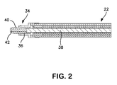
- Fig 2 taken along with Fig. 1, there is shown a side cross sectional view of a portion of the elongated member 22 and, in particular, illustrating the proximal end 34 of the elongated member 22.
- the proximal end 34 includes a circular flange 36 that is dimensioned so as to interfit into the opening 20 in the base 12 in order to affix the elongated member 22 to the base 12.
- an optical fiber 38 that runs the full length of the elongated member 22, that is, from the proximal end 34 to the distal end 24.
- the optical fiber 38 may be protected by a shield 40 that covers the full length of the optical fiber 38.
- the proximal end 34 of the elongated member 22 is affixed firmly within the opening 20 in the base 12 such that the proximal end 42 of the optical fiber 38 is optically located proximate to the illumination source 32 to enable the light from the illumination source 32 to enter the proximal end 42 of the optical fiber 38 so as to transmit that light to the distal end 24 of the elongated member 22.
- Fig. 3 taken along with Figs. 1 and 2, there is shown an exploded view illustrating certain components and the assembly and affixation of the shade assembly 26 to the distal end 24 of the elongated member 22.
- the optical fiber 38 and the elongated member 22 are both affixed to the shade assembly 26 in a manner that facilitates the assembly during the manufacturing process.
- the distal end 44 of the optical fiber 38 is positioned within a fitting 46 that is affixed at the distal end 24 of the elongated member 22.
- a foam washer 48 is slipped over the distal end 44 of the optical fiber 38 and an aperture sleeve 50 is also slipped over that distal end 44.
- a inner flange 52 on the sleeve 50 contacts and pushes the foam washer 48 inwardly and which serves as an inner seal to seal between the optical fiber 38 and the internal diameter of the elongated member 22.
- the distal end 44 of the optical fiber 38 is encased in the aperture sleeve 50 that has an aperture 54 at its external end in order to allow the light to pass from the distal end 44 of the optical fiber 38 into the shade assembly 26 in a manner that will be later explained.
- an elastomeric sleeve 56 comprises of a flexible material and a retention clip 58 that can be made of a steel material having a slit 60 along its length and the purpose of the elastomeric sleeve 56 and the retention clip 58 will be later explained, however at this point in the assembly, the elastomeric sleeve 56 and the retention clip 58 are assembled to the shade assembly 26 by begin slipped over the distal end 24 of the elongated member 22.
- the coupling of the elongated member 22 to the sleeve assembly 26 is accomplished by affixing a shade 62 to the distal end 24 of the elongated member 22.
- the shade 62 has a generally conical shaped body 64 with a large diameter outer end 66 and a small, cylindrical inner end 68. In the assembly, therefore, the cylindrical inner end 68 of the shade 62 is interfitted over the aperture sleeve 52 and inside of the fitting 46.
- apertures 70 there are a plurality of apertures 70, generally two apertures, located 180 degrees apart, in the cylindrical inner end 68 of the shade 62 that align with apertures 72 in the fitting 46 such that pins 74 can be inserted through the respective, aligned apertures 70 and 72 to affix the shade 62 to the fitting 46, thereby, of course, affixing the shade 62 to the distal end 24 of the elongated member 22.
- the retention clip 58 can then be slid distally along the elongated member 22 to a position overlying the pins 74 to retain the pins 74 in their position affixing the shade 62 to the fitting 46.
- the elastomeric sleeve 56 can then also be slipped distally along the elongated member 22 to a position overlying the retention clip 58 to provide a moisture seal over the retention clip 58 as well as other areas of the junction between the elongated member 22 and the shade assembly 26.
- a reflective cone 76 is inserted into the interior of the shade 62 and rests against ribs 78 formed on the interior surface of the shade 62.
- the inner end 80 of the reflective cone 76 fits around the aperture 54 in the aperture sleeve 50 to allow the light emanating from the distal end 44 of the optical fiber 38 to enter and be reflected off of the interior metallized surface of the reflective cone 76.
- a Fresnel lens 82 is located at the distal end outer end 66 of the shade 62 and is preferably made of a plastic material for lightness. Since a Fresnel lens, by definition, has a flat side and a ridged side, in the present construction the flat side is the outer side 84, that is, facing toward the infant and the ridged side is the inner side 86 facing the optical fiber 38. By that orientation it can be assured that the outer side 84 can be easily cleaned by the users since it is flat without the ridges which are difficult to clean.
- the Fresnel lens 82 rests against the outer ends 88 of the ribs 78 to hold the Fresnel lens 82 along its inner side 86 and a wave spring 90 affixes the Fresnel lens to the shade 62.
- the wave spring 90 is better shown in Fig. 4, taken along with Fig. 3 and used to hold the Fresnel lens 82 safely to the outer end 66 of the shade 62.
- the wave spring 90 is a circular ring of overlapping ends and which has waves or various sinusoidal indentations 92 formed therein.
- the Fresnel lens 82 In assembling the Fresnel lens 82 to the outer end 66 of the shade 62, the Fresnel lens 82 is placed into a circular groove 94 formed in the outer end 66 and the wave spring 90 is compressed and sprung open in the annular grove 94 to retain the Fresnel lens 82 firmly in position.
- the shade assembly 26 is affixed to the distal end 24 of the elongated member 22 is a positive manner and yet which does not add significant weight to the distal end 24 of the elongated member 22 so that the phototherapy light device can be held in its desired position over the infant and not sag toward the infant.
- the light originating from the illumination source 32 passes through the optical fiber 38 to the distal end 44 of the optical fiber 38 where it enters the housing shade 62 to impinge on the inner side 86 of the Fresnel lens 82. That ridged inner side 86 then passes the light to the smooth, outer side 84 of the Fresnel lens 82 to be directed toward the infant at the desired area.
- the light can be directed by the user to the desired area of the infant.
- the distal end of the phototherapy light device 10 is sufficiently light as compared to the prior art glass lens unit, to allow the distal end of the phototherapy light device 10 to be safely positioned over an infant and reduce the possibility of sagging and potential touching of the infant.
Landscapes
- Health & Medical Sciences (AREA)
- Engineering & Computer Science (AREA)
- Biomedical Technology (AREA)
- Pathology (AREA)
- Nuclear Medicine, Radiotherapy & Molecular Imaging (AREA)
- Radiology & Medical Imaging (AREA)
- Life Sciences & Earth Sciences (AREA)
- Animal Behavior & Ethology (AREA)
- General Health & Medical Sciences (AREA)
- Public Health (AREA)
- Veterinary Medicine (AREA)
- Radiation-Therapy Devices (AREA)
Abstract
Description
- The present invention relates generally to a phototherapy light for treating infants and, more particularly, to a phototherapy light having an improved lens.
- Hyperbilirubinemia is an affliction of newborn infants typified by an elevated level of a toxic molecule know as bilirubin in the infant's blood. Current medical therapy for such affliction is through the use of phototherapy where light radiation, generally within a certain wavelength band is directed upon the infant's skin.
- There are a number of means or devices that are conventionally employed to direct the light upon the skin of the infant, one of which is to provide a bank of lights that are portable or can be built into an infant care apparatus and which direct the light radiation toward the infant positioned on an infant platform as a part of that apparatus.
- Another means of providing phototherapy is through the use of a fiberoptic pad that is comprised of woven optical fibers such that the light radiation couples out of the optical fibers at the various bends that are formed in the optical fibers during the weaving process.
- A still further means or device is by the use of a "gooseneck" phototherapy device that has a maneuverable, elongated neck that the caregiver can bend to the desired position to direct the light radiation upon the area of the infant where the light radiation is needed.
- With the "gooseneck" type of phototherapy device, the distal end that is positioned so as to direct the light radiation upon the infant conventionally includes a lens that focuses the light radiation to most effectively impinge on the infant.
- One difficulty, however, in the use of the device, is that the lens is comprised of a relatively heavy glass material and, since the distal end of the "gooseneck" can be suspended over the infant, the weight of the lens can cause drooping or sagging of the distal end and can result in the distal end of the "gooseneck" phototherapy device actually contacting the infant. Since the glass lens is normally at an elevated temperature, the contact with the infant is obviously not desirable since it can cause harm to the infant.
- It would be advantageous to have a design and construction of a "gooseneck" type of phototherapy device that provides the necessary alleviation of the bilirubin condition but with a lighter distal end. It would be even further advantageous if the distal end of that phototherapy device were maintained at a relatively low temperature to reduce the potential harm to the infant if there is still an inadvertent contact with an infant.
- Accordingly, one aspect of the present invention relates to a phototherapy light device that is usable in the treatment of bilirubinemia of an infant. With the device of the present invention, the device preferably has a base where the source of illumination is located for the light therapy. Extending from the base is an elongated "gooseneck" type of flexible member that terminates at a distal end. The elongated member encloses a light pipe or optical fiber system that transmits the light from the light source in the base to the distal end where the light can emanate to impinge upon the infant.
- By means of the flexibility of the elongated member, the location of the distal end can be manipulated by the user to direct the light upon the desired area of the infant while the base remains in a stationary position.
- At the distal end of the elongated member, there is a housing that has an opening for the distal end of the optical fiber to retain it in a desired location and the housing flares outwardly in a generally conical configuration to a widened end where there is located a Fresnel lens.
- As such, the light emanating from the distal end of the optical fiber radiates somewhat outwardly in a diverging pattern to reach the inner surface of the Fresnel lens where the light is redirected outwardly from the housing in a generally collimated pattern. In the present invention, the inner surface of the Fresnel lens is ridged and which faces the distal end of the optical fiber while the outer surface that faces the infant is the smooth side of the Fresnel lens.
- The effect of the Fresnel lens is to prevent the buildup of heat that can cause harm to the infant if there is contact therebetween. The Fresnel lens has a larger radius than the prior art glass lens. In addition, the Fresnel lens is preferable plastic so that the combination of the large area and plastic material allows the Fresnel lens to redirect the light without creating significant heat. Thus, the distal end of the phototherapy light device is not greatly heated and the hazard of contact with an infant by a heated surface is eliminated.
- In addition, the Fresnel lens is lighter that the prior use of a glass lens and that lighter construction as well as the particular assembly of the housing to the elongated member also aids in alleviating the problem of the distal end of the phototherapy light device sagging downwardly and possible contacting the infant.
- These and other features and advantages of the present invention will become more readily apparent during the following detailed description taken in conjunction with the drawings herein, in which:
- Fig. 1 is a perspective view of a phototherapy light device constructed in accordance with an embodiment of the present invention;
- Fig. 2 is a side cross sectional view of the elongated member used in an embodiment of the present invention;
- Fig.3 is an exploded view illustrating certain components and their assembly in constructing the phototherapy light device of an embodiment of the present invention; and Fig. 4 is a perspective view of a wave ring used in an embodiment of the invention in the assembly of the phototherapy light device.
- Referring now to Fig. 1, there is shown a perspective view of the
phototherapy light device 10 constructed in accordance with an embodiment of the present invention. As can be seen, thephototherapy light device 10 includes abase 12 and, in the embodiment shown, thebase 12 can be mounted to astand 14 so that thephototherapy light device 10 can be moved to a location proximate to an infant for use in administering phototherapy. As an alternative, thebase 12 can be affixed to an infant care apparatus, such as an incubator or infant warmer or may be physically incorporated into an infant care apparatus. - There can be suitable controls on the
base 12, including apower switch 16 and anintensity control 18 to allow the user to set a desired intensity of the phototherapy light directed onto an infant. In the upper surface of thebase 12 there is an opening 20 where anelongated member 22 is affixed to thebase 12. - The
elongated member 22 itself can be a flexible member such as is used in a gooseneck lamp so that the user can manipulate theelongated member 22 as desired so as to position thedistal end 24 of theelongated member 22 in a particular location to direct the phototherapy light at a selected area of the infant. Affixed to thedistal end 24 of theelongated member 22 is ashade assembly 26 that is generally conical shaped with a reduced diameterproximal end 28 and a larger diameterdistal end 30. - Thus, overall, there is an
illumination source 32 located in thebase 12 and which provides the light that is emitted from thedistal end 30 of theshade assembly 26 to impinge upon the infant. As is conventional, theillumination source 32 can be a light bulb, for example, of about 50 watts, that provides light at the preferred wavelength to alleviate the bilirubinemia. - Turning now to Fig 2, taken along with Fig. 1, there is shown a side cross sectional view of a portion of the
elongated member 22 and, in particular, illustrating theproximal end 34 of theelongated member 22. As can be seen, theproximal end 34 includes acircular flange 36 that is dimensioned so as to interfit into theopening 20 in thebase 12 in order to affix theelongated member 22 to thebase 12. Within theelongated member 22 there is anoptical fiber 38 that runs the full length of theelongated member 22, that is, from theproximal end 34 to thedistal end 24. Theoptical fiber 38 may be protected by ashield 40 that covers the full length of theoptical fiber 38. - Accordingly, in conventional manner, the
proximal end 34 of theelongated member 22 is affixed firmly within theopening 20 in thebase 12 such that theproximal end 42 of theoptical fiber 38 is optically located proximate to theillumination source 32 to enable the light from theillumination source 32 to enter theproximal end 42 of theoptical fiber 38 so as to transmit that light to thedistal end 24 of theelongated member 22. - Turning now to Fig. 3, taken along with Figs. 1 and 2, there is shown an exploded view illustrating certain components and the assembly and affixation of the
shade assembly 26 to thedistal end 24 of theelongated member 22. As will be seen, theoptical fiber 38 and theelongated member 22 are both affixed to theshade assembly 26 in a manner that facilitates the assembly during the manufacturing process. As such, therefore, thedistal end 44 of theoptical fiber 38 is positioned within afitting 46 that is affixed at thedistal end 24 of theelongated member 22. Afoam washer 48 is slipped over thedistal end 44 of theoptical fiber 38 and anaperture sleeve 50 is also slipped over thatdistal end 44. In the process, as thesleeve 50 is placed onto thedistal end 44, ainner flange 52 on thesleeve 50 contacts and pushes thefoam washer 48 inwardly and which serves as an inner seal to seal between theoptical fiber 38 and the internal diameter of theelongated member 22. - Thus the
distal end 44 of theoptical fiber 38 is encased in theaperture sleeve 50 that has anaperture 54 at its external end in order to allow the light to pass from thedistal end 44 of theoptical fiber 38 into theshade assembly 26 in a manner that will be later explained. - In addition, as can be seen, there is an
elastomeric sleeve 56 comprises of a flexible material and aretention clip 58 that can be made of a steel material having aslit 60 along its length and the purpose of theelastomeric sleeve 56 and theretention clip 58 will be later explained, however at this point in the assembly, theelastomeric sleeve 56 and theretention clip 58 are assembled to theshade assembly 26 by begin slipped over thedistal end 24 of theelongated member 22. - The coupling of the
elongated member 22 to thesleeve assembly 26 is accomplished by affixing ashade 62 to thedistal end 24 of theelongated member 22. Theshade 62 has a generally conicalshaped body 64 with a large diameterouter end 66 and a small, cylindricalinner end 68. In the assembly, therefore, the cylindricalinner end 68 of theshade 62 is interfitted over theaperture sleeve 52 and inside of thefitting 46. There are a plurality ofapertures 70, generally two apertures, located 180 degrees apart, in the cylindricalinner end 68 of theshade 62 that align withapertures 72 in thefitting 46 such thatpins 74 can be inserted through the respective, alignedapertures shade 62 to thefitting 46, thereby, of course, affixing theshade 62 to thedistal end 24 of theelongated member 22. - The
retention clip 58 can then be slid distally along theelongated member 22 to a position overlying thepins 74 to retain thepins 74 in their position affixing theshade 62 to the fitting 46. Theelastomeric sleeve 56 can then also be slipped distally along theelongated member 22 to a position overlying theretention clip 58 to provide a moisture seal over theretention clip 58 as well as other areas of the junction between theelongated member 22 and theshade assembly 26. - As such with the
shade 58 to theelongated member 22, the remaining components of theshade assembly 26 can be assembled. Thus, areflective cone 76 is inserted into the interior of theshade 62 and rests againstribs 78 formed on the interior surface of theshade 62. Theinner end 80 of thereflective cone 76 fits around theaperture 54 in theaperture sleeve 50 to allow the light emanating from thedistal end 44 of theoptical fiber 38 to enter and be reflected off of the interior metallized surface of thereflective cone 76. - A Fresnel
lens 82 is located at the distal endouter end 66 of theshade 62 and is preferably made of a plastic material for lightness. Since a Fresnel lens, by definition, has a flat side and a ridged side, in the present construction the flat side is theouter side 84, that is, facing toward the infant and the ridged side is theinner side 86 facing theoptical fiber 38. By that orientation it can be assured that theouter side 84 can be easily cleaned by the users since it is flat without the ridges which are difficult to clean. - As can be seen, the Fresnel
lens 82 rests against theouter ends 88 of theribs 78 to hold the Fresnellens 82 along itsinner side 86 and awave spring 90 affixes the Fresnel lens to theshade 62. Thewave spring 90 is better shown in Fig. 4, taken along with Fig. 3 and used to hold the Fresnellens 82 safely to theouter end 66 of theshade 62. Basically, thewave spring 90 is a circular ring of overlapping ends and which has waves or varioussinusoidal indentations 92 formed therein. In assembling the Fresnellens 82 to theouter end 66 of theshade 62, the Fresnellens 82 is placed into acircular groove 94 formed in theouter end 66 and thewave spring 90 is compressed and sprung open in theannular grove 94 to retain the Fresnellens 82 firmly in position. - As described and shown, therefore, it can be seen that the
shade assembly 26 is affixed to thedistal end 24 of theelongated member 22 is a positive manner and yet which does not add significant weight to thedistal end 24 of theelongated member 22 so that the phototherapy light device can be held in its desired position over the infant and not sag toward the infant. - Therefore, with various embodiments of the present invention, the light originating from the
illumination source 32 passes through theoptical fiber 38 to thedistal end 44 of theoptical fiber 38 where it enters thehousing shade 62 to impinge on theinner side 86 of theFresnel lens 82. That ridgedinner side 86 then passes the light to the smooth,outer side 84 of theFresnel lens 82 to be directed toward the infant at the desired area. - By means of the "gooseneck" elongated
member 22, the light can be directed by the user to the desired area of the infant. By the particular arrangement of affixing theshade assembly 26 to theelongated member 22, and the use of a light, plastic Fresnel lens, the distal end of thephototherapy light device 10 is sufficiently light as compared to the prior art glass lens unit, to allow the distal end of thephototherapy light device 10 to be safely positioned over an infant and reduce the possibility of sagging and potential touching of the infant. - Those skilled in the art will readily recognize numerous adaptations and modifications which can be made to the phototherapy light device of embodiments of the present invention which will result in an improved phototherapy system for an infant care apparatus, yet all of which will fall within the scope and spirit of the present invention as defined in the following claims. Accordingly, the invention is to be limited only by the following claims and their equivalents.
-
10 phototherapy light device 12 base 14 stand 16 power switch 18 intensity control 20 opening - in base 22 elongated member 24 distal end - of elongated member 26 shade assembly 28 proximal end - of shade assembly 30 distal end - of shade assembly 32 illumination source 34 proximal end - of elongated member 36 circular flange 38 optical fiber 40 shield 42 proximal end - of optical fiber 44 distal end - of optical fiber 46 fitting 48 foam washer 50 aperture sleeve 52 inner flange 54 aperture 56 elastomeric sleeve 58 retention clip 60 slit 62 shade 64 conical shaped body - of shade 6266 outer end - of shade 68 inner end - of shade 70 aperture - in inner end of shade 72 aperture - in fitting 4674 pin 76 reflective cone 78 rib 80 inner end - of reflective cone 82 Fresnellens 84 outer side - of Fresnel lens 86 inner side - of Fresnel lens 88 outer ends - of ribs 90 wave spring 92 sinusoidal indentations- in wave spring 94 circular groove
Claims (10)
- A phototherapy light device (10) for treating infants, the phototherapy light device (10) comprising a base (12), an elongated member (22) having an outer end (24) extending from the base (12), a shade (62) located at the outer end (24) of the elongated member (22), the shade (62) having a distal end (66) extending away from the elongated member (22), a source of light (32) to provide light radiating from the distal end (66) of the shade (62), the elongated member (22) being maneuverable so as to direct the light radiating from the distal end (66) of the shade (62) to impinge on an infant, and a Fresnel lens (82) located at the distal end (66) of the shade (62) wherein the light radiated from the distal end (62) of the shade (62) passes through the Fresnel lens (82).
- The phototherapy light device (10) as defined in claim 1 wherein the source of light (32) comprises a bulb located in the base (12) and an optical fiber (38) system that transmits the light from the bulb to the distal end (66) of the shade (62).
- The phototherapy light device (10) as defined in claim 1 or claim 2 wherein the Fresnel lens (82) has a smooth surface (84) facing outwardly toward an infant and a ridged surface (86) facing inwardly toward the elongated member (22).
- The phototherapy light device (10) as defined in any preceding claim wherein the shade (62) is affixed to the elongated member (22) by means of pins (74).
- The phototherapy light device (10) as defined in any preceding claim wherein the Fresnel lens (62) is affixed to the distal end (66) of said shade (62) by means of a wave spring (90).
- A infant care apparatus, said infant care apparatus comprising a structure having a phototherapy light device (10) affixed to the structure, the phototherapy light device (10) comprising a base (12), an elongated member (22) having an outer end (24) extending from the base (12), a shade (62) located at the outer end (24) of the elongated member (22), the (62) shade having a distal end (66), a source of light (32) to provide light radiating from the distal end (66) of the shade (62), the elongated member (22) being maneuverable so as to direct the light radiating from the distal end (66) of the shade (62) to impinge on an infant when resting on the infant care apparatus, and a Fresnel lens (82) located at the distal end (66) of the shade (62) wherein the light radiated from said distal end (66) of said shade (62) passes through the Fresnel lens (82).
- The infant care apparatus as defined in claim 6 wherein the source of light (32) comprises a bulb located in the base (12) and an optical fiber system (38) that transmits the light from the bulb to the distal end (66) of the shade (62).
- The infant care apparatus as defined in claim 6 or claim 7 wherein the Fresnel lens (82) has a smooth surface (84) facing outwardly toward an infant and a ridged surface (86) facing inwardly toward the elongated member (22).
- A method of providing phototherapy light to an infant comprising the steps of:providing a base (12) having an elongated member (22) extending therefrom and having a shade (62) located at an outer end (24) of the elongated member (22), the shade (62) having a distal end (66) adapted to be positionable at a desired location with respect to an infant,causing light to be emitted from the distal end (66) of the shade (62),providing a Fresnel lens (82) at the distal end (66) of the shade (62) such that the light emitted from the shade (62) passes through the Fresnel lens (82).
- The method as defined in claim 9 wherein the step of providing a Fresnel lens (82) comprises providing a Fresnel lens (82) that is oriented to have its ridged side (86) facing the elongated member and its smooth side (84) facing an infant.
Applications Claiming Priority (1)
| Application Number | Priority Date | Filing Date | Title |
|---|---|---|---|
| US11/327,554 US20070162091A1 (en) | 2006-01-06 | 2006-01-06 | Phototherapy light with fresnel lens for infant care apparatus |
Publications (1)
| Publication Number | Publication Date |
|---|---|
| EP1813307A1 true EP1813307A1 (en) | 2007-08-01 |
Family
ID=37898295
Family Applications (1)
| Application Number | Title | Priority Date | Filing Date |
|---|---|---|---|
| EP07100083A Withdrawn EP1813307A1 (en) | 2006-01-06 | 2007-01-04 | Phototherapy light with fresnel lens for infant care apparatus |
Country Status (4)
| Country | Link |
|---|---|
| US (1) | US20070162091A1 (en) |
| EP (1) | EP1813307A1 (en) |
| JP (1) | JP2007181685A (en) |
| CA (1) | CA2572844A1 (en) |
Families Citing this family (3)
| Publication number | Priority date | Publication date | Assignee | Title |
|---|---|---|---|---|
| TWM350190U (en) * | 2008-08-29 | 2009-02-01 | Lumens Digital Optics Inc | Digital presenter using gooseneck |
| JP6318134B2 (en) * | 2015-11-18 | 2018-04-25 | アトムメディカル株式会社 | Incubator with lighting equipment for newborns |
| US11058596B2 (en) | 2017-06-28 | 2021-07-13 | General Electric Company | Autoregulation of irradiance in phototherapy systems |
Citations (3)
| Publication number | Priority date | Publication date | Assignee | Title |
|---|---|---|---|---|
| WO1989000871A1 (en) * | 1987-07-24 | 1989-02-09 | Katona Belane | Apparatus for irradiating by polarised light |
| US4911166A (en) * | 1988-03-11 | 1990-03-27 | The United States Of America As Represented By The Department Of Health And Human Services | Portable light delivery system |
| JPH0954274A (en) * | 1995-08-18 | 1997-02-25 | Tokyu Constr Co Ltd | Lighting method and lighting device |
Family Cites Families (15)
| Publication number | Priority date | Publication date | Assignee | Title |
|---|---|---|---|---|
| SE455837B (en) * | 1983-12-23 | 1988-08-15 | Bildsystem Ab | PROJECTOR FOR MAKING POLARIZED LIGHT, FOR BIOSTIMULATION |
| US4690141A (en) * | 1985-09-16 | 1987-09-01 | Castel John C | Fresnel lens light applicator |
| US4710013A (en) * | 1985-10-08 | 1987-12-01 | W. Haking Enterprises Limited | Automatic focusing mechanism for camera |
| US5441531A (en) * | 1993-10-18 | 1995-08-15 | Dusa Pharmaceuticals Inc. | Illuminator and methods for photodynamic therapy |
| US6234640B1 (en) * | 1998-05-22 | 2001-05-22 | Bruce D. Belfer | Fiber optic replicant lamp |
| JP3005687B2 (en) * | 1998-05-28 | 2000-01-31 | スタンレー電気株式会社 | Lamp |
| US6056426A (en) * | 1998-09-28 | 2000-05-02 | Federal Signal Corporation | Monolithic beam shaping light output light device |
| AU2489901A (en) * | 2000-03-08 | 2001-09-13 | Fisher & Paykel Healthcare Limited | Radiant warmer |
| AU2002245163A1 (en) * | 2000-10-20 | 2002-07-24 | Photomedex | Controlled dose delivery of ultraviolet light for treating skin disorders |
| DE10123785A1 (en) * | 2001-05-16 | 2002-11-21 | Leica Microsystems | Device for illuminating a field of view, for example an object field under a microscope by two light sources |
| US20050122509A1 (en) * | 2002-07-18 | 2005-06-09 | Leica Microsystems Semiconductor Gmbh | Apparatus for wafer inspection |
| US6724543B1 (en) * | 2002-10-23 | 2004-04-20 | Visteon Global Technologies, Inc. | Light collection assembly having mixed conic shapes for use with various light emitting sources |
| US7163329B2 (en) * | 2003-03-07 | 2007-01-16 | Fiberstars, Inc. | Adjustable light pipe fixture |
| DE102004018424B4 (en) * | 2004-04-08 | 2016-12-08 | Docter Optics Se | Process for producing a lens |
| US20060232977A1 (en) * | 2005-04-13 | 2006-10-19 | Ching-Hsien Hwang | Lens assembly |
-
2006
- 2006-01-06 US US11/327,554 patent/US20070162091A1/en not_active Abandoned
- 2006-12-28 JP JP2006353663A patent/JP2007181685A/en not_active Withdrawn
-
2007
- 2007-01-04 CA CA002572844A patent/CA2572844A1/en not_active Abandoned
- 2007-01-04 EP EP07100083A patent/EP1813307A1/en not_active Withdrawn
Patent Citations (3)
| Publication number | Priority date | Publication date | Assignee | Title |
|---|---|---|---|---|
| WO1989000871A1 (en) * | 1987-07-24 | 1989-02-09 | Katona Belane | Apparatus for irradiating by polarised light |
| US4911166A (en) * | 1988-03-11 | 1990-03-27 | The United States Of America As Represented By The Department Of Health And Human Services | Portable light delivery system |
| JPH0954274A (en) * | 1995-08-18 | 1997-02-25 | Tokyu Constr Co Ltd | Lighting method and lighting device |
Also Published As
| Publication number | Publication date |
|---|---|
| US20070162091A1 (en) | 2007-07-12 |
| CA2572844A1 (en) | 2007-07-06 |
| JP2007181685A (en) | 2007-07-19 |
Similar Documents
| Publication | Publication Date | Title |
|---|---|---|
| US4782818A (en) | Endoscope for guiding radiation light rays for use in medical treatment | |
| JP5238077B2 (en) | Device for providing UV light therapy | |
| US9283292B2 (en) | Device for use in a medical treatment room | |
| US5072349A (en) | Lighting device for surgical and medical uses | |
| US6739744B2 (en) | Light delivery systems and applications thereof | |
| CN101754783B (en) | Infant phototherapy device | |
| CA2139820C (en) | Fiberoptic illuminator for infant care | |
| CN101808565A (en) | Flexible infrared delivery apparatus and method | |
| US20060217787A1 (en) | Light therapy device | |
| JPS6033071B2 (en) | Surgical blunt hook | |
| KR20210001284A (en) | rhinitis therapeutic device | |
| EP1847293A2 (en) | Phototherapy light with dual spring support neck | |
| US4884568A (en) | Radiation coagulator | |
| EP1813307A1 (en) | Phototherapy light with fresnel lens for infant care apparatus | |
| JP2005125097A (en) | Integrated procedure light for infant care apparatus | |
| KR101865784B1 (en) | Laser and handpiece to beak down fat in body | |
| US7991260B2 (en) | Light-diffusing safety cap | |
| US4901724A (en) | Light ray radiation device for use in medical treatment | |
| KR890000788B1 (en) | A light bath | |
| KR102146759B1 (en) | Multi-purpose portable light treatment device | |
| US4796967A (en) | Solar ray energy radiation device for use in medical treatment | |
| CN212941022U (en) | Hand-held type ultraviolet lamp | |
| EP4271333B1 (en) | Device for treating dry eyes | |
| KR200245818Y1 (en) | laser appliance for medical freatment | |
| CN213666708U (en) | Physical therapy device |
Legal Events
| Date | Code | Title | Description |
|---|---|---|---|
| PUAI | Public reference made under article 153(3) epc to a published international application that has entered the european phase |
Free format text: ORIGINAL CODE: 0009012 |
|
| AK | Designated contracting states |
Kind code of ref document: A1 Designated state(s): AT BE BG CH CY CZ DE DK EE ES FI FR GB GR HU IE IS IT LI LT LU LV MC NL PL PT RO SE SI SK TR |
|
| AX | Request for extension of the european patent |
Extension state: AL BA HR MK YU |
|
| 17P | Request for examination filed |
Effective date: 20080201 |
|
| AKX | Designation fees paid |
Designated state(s): DE FR GB |
|
| 17Q | First examination report despatched |
Effective date: 20080326 |
|
| STAA | Information on the status of an ep patent application or granted ep patent |
Free format text: STATUS: THE APPLICATION IS DEEMED TO BE WITHDRAWN |
|
| 18D | Application deemed to be withdrawn |
Effective date: 20080806 |