US7163329B2 - Adjustable light pipe fixture - Google Patents
Adjustable light pipe fixture Download PDFInfo
- Publication number
- US7163329B2 US7163329B2 US10/793,049 US79304904A US7163329B2 US 7163329 B2 US7163329 B2 US 7163329B2 US 79304904 A US79304904 A US 79304904A US 7163329 B2 US7163329 B2 US 7163329B2
- Authority
- US
- United States
- Prior art keywords
- light pipe
- receiver assembly
- bayonet
- coupling
- axial
- Prior art date
- Legal status (The legal status is an assumption and is not a legal conclusion. Google has not performed a legal analysis and makes no representation as to the accuracy of the status listed.)
- Expired - Fee Related, expires
Links
Images


Classifications
-
- F—MECHANICAL ENGINEERING; LIGHTING; HEATING; WEAPONS; BLASTING
- F21—LIGHTING
- F21V—FUNCTIONAL FEATURES OR DETAILS OF LIGHTING DEVICES OR SYSTEMS THEREOF; STRUCTURAL COMBINATIONS OF LIGHTING DEVICES WITH OTHER ARTICLES, NOT OTHERWISE PROVIDED FOR
- F21V19/00—Fastening of light sources or lamp holders
- F21V19/02—Fastening of light sources or lamp holders with provision for adjustment, e.g. for focusing
-
- E—FIXED CONSTRUCTIONS
- E04—BUILDING
- E04B—GENERAL BUILDING CONSTRUCTIONS; WALLS, e.g. PARTITIONS; ROOFS; FLOORS; CEILINGS; INSULATION OR OTHER PROTECTION OF BUILDINGS
- E04B9/00—Ceilings; Construction of ceilings, e.g. false ceilings; Ceiling construction with regard to insulation
- E04B9/006—Ceilings; Construction of ceilings, e.g. false ceilings; Ceiling construction with regard to insulation with means for hanging lighting fixtures or other appliances to the framework of the ceiling
-
- F—MECHANICAL ENGINEERING; LIGHTING; HEATING; WEAPONS; BLASTING
- F21—LIGHTING
- F21S—NON-PORTABLE LIGHTING DEVICES; SYSTEMS THEREOF; VEHICLE LIGHTING DEVICES SPECIALLY ADAPTED FOR VEHICLE EXTERIORS
- F21S8/00—Lighting devices intended for fixed installation
- F21S8/02—Lighting devices intended for fixed installation of recess-mounted type, e.g. downlighters
-
- F—MECHANICAL ENGINEERING; LIGHTING; HEATING; WEAPONS; BLASTING
- F21—LIGHTING
- F21V—FUNCTIONAL FEATURES OR DETAILS OF LIGHTING DEVICES OR SYSTEMS THEREOF; STRUCTURAL COMBINATIONS OF LIGHTING DEVICES WITH OTHER ARTICLES, NOT OTHERWISE PROVIDED FOR
- F21V14/00—Controlling the distribution of the light emitted by adjustment of elements
- F21V14/02—Controlling the distribution of the light emitted by adjustment of elements by movement of light sources
-
- F—MECHANICAL ENGINEERING; LIGHTING; HEATING; WEAPONS; BLASTING
- F21—LIGHTING
- F21V—FUNCTIONAL FEATURES OR DETAILS OF LIGHTING DEVICES OR SYSTEMS THEREOF; STRUCTURAL COMBINATIONS OF LIGHTING DEVICES WITH OTHER ARTICLES, NOT OTHERWISE PROVIDED FOR
- F21V21/00—Supporting, suspending, or attaching arrangements for lighting devices; Hand grips
- F21V21/02—Wall, ceiling, or floor bases; Fixing pendants or arms to the bases
- F21V21/04—Recessed bases
-
- G—PHYSICS
- G02—OPTICS
- G02B—OPTICAL ELEMENTS, SYSTEMS OR APPARATUS
- G02B6/00—Light guides; Structural details of arrangements comprising light guides and other optical elements, e.g. couplings
- G02B6/0001—Light guides; Structural details of arrangements comprising light guides and other optical elements, e.g. couplings specially adapted for lighting devices or systems
- G02B6/0005—Light guides; Structural details of arrangements comprising light guides and other optical elements, e.g. couplings specially adapted for lighting devices or systems the light guides being of the fibre type
- G02B6/0008—Light guides; Structural details of arrangements comprising light guides and other optical elements, e.g. couplings specially adapted for lighting devices or systems the light guides being of the fibre type the light being emitted at the end of the fibre
Definitions
- the present invention relates to fixtures for a light pipe with various features for conveniently installing the fixtures in a ceiling, for instance.
- the lighting consumer has several options to install adjustable light today. For very large fixtures used in factories or warehouses, there are often one or two settings for a socket within a large reflector. By moving the socket, a customer can change the beam spread to a few different settings, but this is rarely done because of the difficulty involved. Instead, the fixtures are usually set in the factory and never changed.
- a second option available today is to use lamps with integral reflectors that have different beam spreads.
- One example of this is low voltage halogen lamps, of which MR-16 is a common type.
- the MR-16 lamps are available in several light beam spreads from very narrow spot lights (with angular extents of about 7 degrees) to very wide flood lights (with angular extents of about 60 degrees).
- the most common beam spreads for the accent-lighting applications where MR-16s are used are 15, 25 and 40 degrees. This strategy causes complications when lamps are changed after burning out. All MR-16s are very similar in appearance, and beam patterns within a space are only maintained after re-lamping if the exact same lamp is used to replace the burned out lamp. This strategy also requires many different lamp types to be kept on hand.
- Fiber optic lighting has historically offered an easier option for adjusting beam spread. Because fiber optic lighting delivers lighting in a forward direction of usually less than about one steradian, it can easily be controlled with imaging or non imaging lenses. By moving the fiber output face with relation to the beam forming lens, different beam spreads can be achieved. Fiber optic lighting fixtures exist today which allow infinite adjustment of the distance from the lens to the fiber. Sometimes these fixtures will have visual guides to help the installer guide the beam setting to the desired angular setting. Because there is infinite adjustment, and only a visual guide to beam setting, in any field of fixtures that are desired to be at the same beam angle, significant variation will be observed. So, the beam-angle accuracy is limited to the skill of the installer.
- the invention provides, in a preferred form, a light pipe fixture with adjustable beam spreads.
- the fixture comprises a bayonet assembly having a generally tubular coupling for receiving a light-dispensing end of a light pipe, and a receiver assembly.
- the receiver assembly has a generally tubular coupling for receiving therewithin the bayonet assembly coupling at adjustable levels of penetration of the bayonet assembly coupling within the receiver assembly coupling.
- the receiver assembly further comprises an optical lens and a hollow portion for focusing a light beam from the end of the light pipe through the lens.
- the radial interior surface of the receiver assembly coupling and the radial exterior surface of the bayonet assembly coupling are so configured that the receiver assembly coupling slidably and lockingly receives the bayonet assembly coupling in any of a plurality of positions along the length of the receiver assembly coupling, so as to allow for different discrete distances between the end of the fiber and the lens.
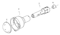
- FIG. 1 is an isometric, exploded view of a bayonet assembly, light pipe, receiver assembly and lens in accordance with the invention.
- FIG. 2 a is a side view of the bayonet assembly and light pipe of FIG. 1 ;
- FIG. 2 b is a sectional view of FIG. 2 a taken at Arrows 2 b — 2 b in FIG. 2 a ;
- FIG. 2 c is an enlargement of the circled portion of FIG. 2 b labeled FIG. 2 c.
- FIG. 3 a is a side view of the receiver assembly of FIG. 1 ;
- FIG. 3 b is a sectional view of FIG. 3 a taken at Arrows 3 b — 3 b in FIG. 3 a ;
- FIG. 3 c is an enlargement of the circled portion of FIG. 3 b labeled FIG. 3 c.
- FIGS. 4 a – 4 c are isometric views, partially cutaway, of initial relative positions of the bayonet and receiver assemblies of FIG. 1 for attaining different light beam spreads.
- FIG. 5 is an isometric view of the bayonet assembly of FIG. 1 .
- FIG. 6 a is a sectional, isometric view of the receiver assembly of FIG. 1 ; and FIG. 6 b is an enlargement of the circled portion in FIG. 6 a labeled FIG. 6 b.
- FIG. 7 a is an isometric view of a bayonet assembly and a receiver assembly, with the receiver assembly shown without the surface on which positioning pads and circumferential flange stops are mounted, for simplicity of illustration; and FIG. 7 b is an enlargement of the circled portion in FIG. 7 a labeled FIG. 7 b.
- FIGS. 8 a – 8 c show isometric views of a bayonet assembly and receiver assembly in various stages of interconnection for selecting a 15-degree light beam spread, with outer portions of the bayonet assembly removed or broken away to show more clearly positioning pads and attached circumferential flange stops of the receiver assembly; and
- FIG. 8 d is an enlargement of the circled portion in FIG. 8 c labeled FIG. 8 d.
- FIG. 8 e is an isometric view of a portion of the bayonet and receiver assemblies of FIG. 1 , partially in cross section, with an outer portion of the bayonet assembly removed to show more clearly a radial-bearing region; and FIG. 8 f is an enlargement of the circled portion in FIG. 8 e labeled FIG. 8 f , shown partially broken away.
- FIG. 8 g is an isometric view of the bayonet and receiver assemblies of FIG. 1 .
- the figure shows the receiver assembly partially in cross section and with an outer portion removed in the vicinity of the bayonet assembly to portray more clearly a radial-bearing section of the receiver assembly.
- FIG. 9 a is an upper isometric view, partially cutaway, of a fixed-angle ceiling mount installation using the bayonet and receiver assemblies of FIG. 1 ; and FIG. 9 b is a simplified enlargement of the circled portion in FIG. 9 a labeled FIG. 9 b.
- FIGS. 10 a – 10 c show parts of the structure of FIG. 9 a as viewed at Arrows 10 a — 10 a in FIG. 9 a and are partially in cross section, the different figures showing different heights of the bayonet assembly relative to a sled.
- FIG. 11 is an upper isometric view, partially cutaway, of an adjustable-angle ceiling mounting fixture using the bayonet and receiver assemblies of FIG. 1 .
- FIG. 12 a is an isometric view of the bayonet and receiver assemblies of FIG. 1 , including a beauty ring as also shown in FIG. 11 ; and FIG. 12 b is an enlargement of the circled portion of FIG. 12 a labeled FIG. 12 b.
- FIGS. 12 c and 12 d are like FIGS. 12 a and 12 b , respectively, but show the beauty ring further away from the receiver assembly.
- FIG. 13 a is an exploded, isometric view of the bayonet and receiver assembly of FIG. 1 , showing a different beauty ring that may be accommodated.
- FIG. 13 b is a side plan view of the arrangement of FIG. 13 a ; and FIG. 13 c is an enlargement of the circled portion of FIG. 13 b labeled FIG. 13 c.
- FIG. 13 d is a side plan view of the arrangement of FIG. 13 a ; and FIG. 13 e is an enlargement of the circled portion of FIG. 13 d labeled FIG. 13 e.
- This description covers three features relating to (1) bayonet and receiver assemblies, (2) a fixed-angle ceiling mount installation, and (3) an adjustable-angle ceiling mount installation.
- FIG. 1 shows a bayonet assembly 10 and cooperating receiver assembly 12 , which holds a lens 14 .
- lens 14 may be a plano-convex lens, an aspherical lens, a holographic lens, a Fresnel lens or a flat lens, made from either glass or plastic.
- bayonet assembly 10 uses an internal lip 18 ( FIG. 2 c ) to stop the inserted light pipe at a precise location.
- receiver assembly 12 utilizes an internal shelf 20 ( FIG. 3 c ) and radial snaps 22 ( FIG. 3 c ) to lock the lens into a precise location.
- radial snaps 22 preferably two in number, preferably occupy between about 5 and 20 degrees of circumference about a longitudinal axis 24 of such assembly, and more preferably between about 5 and 15 degrees.
- ABS Acrylonitrile Butadiene Styrene
- the ABS for the receiver assembly is “platable” in that it can accept such coatings as chrome or brass, for reflective purposes.
- FIGS. 4 a – 4 c show respective, initial relative positions of bayonet assembly 10 and receiver assembly 12 for achieving light beam spreads exiting lens 14 of degrees of 15, 25 and 40, respectively, by way of example.
- a notch 28 or other mark on receiver assembly 12 is aligned with markings on the bayonet assembly 10 for a desired degree of beam spread; for instance, FIG. 4 a showing notch 28 aligned with “15” for a 15-degree beam spread.
- Each of the various beam spread adjustment locations is clearly marked on bayonet.
- a user inserts bayonet assembly 10 into receiver assembly 12 as shown in any of FIGS. 4 a – 4 c until the bayonet assembly reaches a full stop within receiver assembly 10 .
- the user then rotates the bayonet assembly relative to the receiver assembly in the direction of an arrow 30 until a full rotational stop is reached, at which point the bayonet assembly becomes locked to the receiver assembly.
- the rotation of bayonet assembly 10 relative to receiver assembly 12 is 1/12 th turn, or 30 degrees.
- bayonet assembly 10 uses an axial stop ledge 32 and circumferential lock flange 34 that extend radially outwards from a substantially cylindrical surface 36 , which is a surface that radially bears against cooperating surfaces of receiver assembly 12 .
- Axial stop ledge 32 is axially aligned with lock flange 34 .
- the additional geometric structures on the bayonet assembly (e.g., 37 ) allow for clearance for different beam-spread positions and may also block contaminants, as described below.
- bayonet assembly 10 forms a pattern from about 180 degrees about a longitudinal axis 38 of the assembly, which pattern repeats for the other approximately 180 degrees about such longitudinal axis. This same approximately 180-degree repeating of patterns applies also to receiver assembly 12 .
- receiving channels 40 circumferential flange stops 42 and axial positioning pads 44 are shown extending radially inwardly from a generally cylindrical surface 46 .
- Flange stops 42 and positioning pads 44 are mounted on a radial bearing region 45 , which extends towards axis 38 from surface 46 .
- Radial bearing surface 45 supports radial bearing loads when the bayonet assembly is inserted into the receiver assembly, and structurally supports positioning pads 44 . Another function of radial bearing surface 45 will be described below.
- circumferential lock flange 34 ( FIG. 5 ) is guided into a receiving channel 40 ( FIG. 6 a ), such as vertically middle-shown channel 40 , until axial stop ledge 32 ( FIG. 5 ) abuts the vertically lowermost-shown positioning pad 44 ( FIG. 6 a ).
- bayonet assembly 10 is then turned 30° clockwise relative to receiver assembly 12 so that circumferential lock flange 34 ( FIG. 5 ) passes a cam lock point (or projection) 48 ( FIG. 6 b ) to lock the circumferential lock flange against a circumferential flange stop.
- a positioning pad 44 ( FIG. 6 a ) is sandwiched in the axial space between circumferential stop flange 34 and axial stop ledge 32 .
- This operation can be more easily understood with reference to FIGS. 7 a – 7 b and 8 a – 8 c.
- FIG. 7 a shows bayonet assembly 10 with axial stop ledge 32 , circumferential lock flange 34 and additional structure 37 .
- FIG. 7 a also shows receiver assembly 12 with circumferential flange stops 42 and axial positioning pads 44 .
- FIG. 7 a has been simplified by omitting the mounting surface for these stops 42 and pads 44 , as is shown at 45 in FIG. 6 a ; and
- FIG. 7 b shows these structures as six stops 42 a – 42 f and six pads 44 a – 44 f .
- the number of stops and pads be four, six (as shown) or eight.
- FIGS. 8 a – 8 c show the selection of a 15-degree beam spread.
- FIG. 8 a shows the insertion of circumferential lock flange 34 into the receiving channel 40 between axial positioning pads 44 a and 44 b .
- FIG. 8 b shows the final extent of insertion of lock flange 34 , when axial stop ledge 32 abuts axial positioning pad 44 a .
- bayonet assembly 10 is then rotated 30 degrees clockwise relative to receiver assembly 12 , as shown in FIG. 8 c , at which point axial positioning pad 44 b is sandwiched between axial stop ledge 32 and circumferential lock flange 34 .
- FIG. 8 e shows bayonet assembly 10 and receiver assembly 12 .
- This figure shows assembly 10 partially in cross section and with an outer portion removed to show more clearly radial-bearing region 45 , described above in connection with FIG. 6 a .
- the enlarged view of FIG. 8 f shows radial-bearing region 45 of receiver assembly 12 supporting positioning pads 44 a and 44 b .
- Surface 32 a of axial stop ledge 32 of the bayonet assembly axially abuts positioning pad 44 b , similar to the position shown in FIG. 8 b .
- annular shelf 55 of radial-bearing region 45 forms a continuous annular surface with positioning pad 44 b , which continuous annular surface fully supports the entire surface 32 a of ledge 32 . This provides a stable coupling between the bayonet and receiver assemblies, and help assure that the locking action described above in connection with FIG. 6 b will reliably occur.
- annular shelves such as that shown in FIG. 8 f at 55 are associated with positioning pads 44 b and 44 c ( FIG. 7 b ), but not with positioning pad 44 a.
- bayonet assembly 10 and receiver assembly 12 were designed as molded components, with bayonet assembly 10 of polycarbonate plastic and receiver assembly of platable ABS, as mentioned above. This provides low cost and an easily reproducible product.
- the present design blocks contaminants from reaching the light pipe.
- such interstices are configured to block any direct path for contaminants to reach the light-dispensing end of the light pipe when the bayonet assembly is locked in position with the receiver assembly. This is shown in FIG. 8 g , wherein structure 37 of bayonet assembly cooperates with radial-bearing region 45 of the receiver assembly to block a direct path for contaminants to reach the light pipe when the bayonet and receiver assemblies are locked together.
- 8 g shows interstice 56 a between circumferentially adjacent surfaces of 37 and 45 , interstice 56 b between axially adjacent surfaces of 37 and 45 , and interstice 56 c between radially adjacent surfaces 56 c .
- the foregoing design is considered closed, since it does not allow a direct path for dust, spray, or insects to reach the light pipe end.
- the receiver assembly in particular, was the most difficult to design for molding as a component that was closed to contaminants as described above.
- the small bore size of the receiver assembly's area for receiving the bayonet assembly typically about 20 mm—made any common undercut (or snap pocket) impossible to mold.
- the receiver assembly's bore size needed to be kept small to keep the costs of the components and associated tooling reasonable and practical, as well to allow for mounting practical component sizes.
- the illustrated design of the bayonet and receiver assemblies allows for the successful molding of these components, as well as maintaining the small bore size and closure of any direct path for contaminants to reach the light pipe end.
- the light pipe fixture described above including bayonet assembly and receiving assembly, is the base unit to a fixed-angle ceiling mount installation shown in FIG. 9 a.
- FIG. 9 a shows a compression fitting 60 for holding bayonet assembly 10 to a sled 62 that is mounted on a pair of rails 64 and 65 , which may be conventional Part No. 512HD sold by Erico International Corporation of Solon, Ohio. These rails have clamps 64 a and 65 a for attaching to the a standard “T” bar grid (e.g., 66 a , 66 b ) for supporting ceiling tiles 67 and 70 , for instance. Rails 64 and 65 , in turn, are mounted above a ceiling tile 67 , which may be a conventional ceiling tile used in office buildings.
- Light pipe 16 is supplied from a protective feeder pipe 68 , mounted on a bracket 69 , which in turn is mounted above another ceiling tile.
- compression fitting 60 compresses against bayonet assembly 10 , rather than against light pipe 16 as is traditional. Beneficially, this prevents kinking of light pipe 16 with resulting light output loss and damage upon installation
- FIG. 9 b shows details of compression fitting 60 and associated structure, including bayonet assembly 10 , receiver assembly 12 and light pipe 16 .
- Compression fitting has a cylindrical shank 60 a with threads above a fixed nut 60 b on which a threaded compression nut 60 c is received, and threads below fixed nut 60 b for receiving a nut 60 d .
- the upper portion 60 e of shank 60 a is not threaded, but rather has vertically extending slots (not shown).
- the vertical slots form a generally cylindrical structure that is compressed against the upper portion of bayonet assembly 10 to fix compression fitting 60 in relation to the bayonet assembly.
- Nut 60 d then torques an annular portion of sled 62 against fixed nut 60 b , so as to fix compression fitting 60 in relation to sled 62 .
- bayonet assembly 10 holds receiver assembly 12 in place, due to their mutual lock-in arrangement described above. With the mounting arrangement of FIG. 9 a , the angle of receiver assembly 12 and its lens remains fixed relative to the associated ceiling tile 67 .
- the height of bayonet assembly 10 can be adjusted vertically along the longitudinal axis of compression fitting 60 . This is important to be able to accommodate ceiling tiles of different thicknesses, as shown in FIGS. 10 a – 10 c .
- FIGS. 10 a – 10 c show three different height adjustments of bayonet assembly 10 , for accommodating ceiling tiles 67 a , 67 b and 67 c of different thicknesses; for instance, thickness 84 a ( FIG. 10 a ) of 0.5 inch, 84 b ( FIG. 10 b ) of 1 inch, and 84 c ( FIG. 10 c ) 1.5 inch.
- sled 62 is inverted from its position in FIGS. 10 a and 10 b.
- sled 62 is shown mounted on rails 64 and 65 .
- the sled can attach to other mounting means such as a so-called Butterfly Mount.
- Butterfly Mount is sold, for instance, by RSA Lighting LLC of Chatsworth, Calif., as part light fixture assembly Part No. CO111STR.
- Other mounting means will be apparent to those of ordinary skill in the art based on the present specification.
- Such other mounting means may allow sled 62 to slide to different positions or to otherwise be mounted in different position, or may only allow mounting in a fixed position.
- FIG. 11 shows a flexible gooseneck 90 , which, once bent, retains its position.
- the flexible portion of gooseneck 90 may comprise helically wound metal (not shown) as is conventional, and the ends 90 b and 90 c of the gooseneck may include cylindrical sleeves.
- Sleeve 90 b mounts about bayonet assembly 10 and is held with adhesive.
- Gooseneck 90 may be a conventional Part No. 96070 sold by Moffatt Products, Inc. Inc. of Watertown, S. Dak.
- Compression fitting 61 which is typically larger than compression fitting 60 of FIG. 9 a , compresses against flexible portion 90 a of gooseneck 90 , rather than against light pipe 16 as is traditional. Beneficially, this prevents kinking of light pipe 16 and resulting light output loss and damage upon installation.
- the angle of direction of receiver assembly 12 can be easily, and repeatedly, manipulated as desired.
- the receiver assembly described herein may be designed to accommodate various beauty rings and an optional filter (not shown).
- Optional filters may comprise a beam-filtering lens, a coloring lens or a diffusing lens, by way of example.
- FIG. 12 a shows a beauty ring 120 affixed to receiver assembly 12 tightly; that is, without clearance required for a typical optional filter of about 4 mm thickness.
- Ring 120 has a pair of similar, axially extending first and second latches 130 a and 130 b (behind assembly 12 ).
- the lower end of receiver assembly 12 has similar first and second recesses 136 a and 136 b (behind assembly 12 ) for receiving first and second latches 130 a and 130 b .
- FIG. 12 a shows a beauty ring 120 affixed to receiver assembly 12 tightly; that is, without clearance required for a typical optional filter of about 4 mm thickness.
- Ring 120 has a pair of similar, axially extending first and second latches 130 a and 130 b (behind assembly 12 ).
- the lower end of receiver assembly 12 has similar first and second recesses 136 a and 136 b (behind assembly 12 ) for receiving first and second latches 130 a
- recess 136 a has a central path 137 a extending axially, and first and second paths 137 b and 137 c extending in opposite circumferential directions from the central path at respectively different axial positions.
- the entranceways to first and second paths 137 b and 137 c have respective cam lock ramps 138 and 139 , for locking beauty ring 120 onto receiver assembly 12 .
- FIG. 13 a shows bayonet assembly 10 , receiver assembly 12 and lens 14 , and a beauty ring 150 that can be used instead of ring 120 shown in FIGS. 12 a – 12 d .
- Ring 150 includes a pair of axially extending mounting arms 152 a and 152 b (shown behind beauty ring 150 ).
- Receiver assembly 12 includes a pair of mounting apertures 154 a and 154 b for respectively receiving the mounting arms 152 a and 152 b.
- mounting arm 152 a includes a pair of axially spaced mounting valleys 156 a and 156 b that face radially and preferably radially outwards from a longitudinal axis of receiver assembly 12 .
- mounting aperture 154 a includes a mounting ridge 157 for selectively being received in one or the other of mounting valley 156 a or 156 b .
- mounting ridge 157 is received in mounting valley 156 a , leaving insufficient space to accommodate an optional 4 mm thick filter.
- the beauty ring can be easily mounted to the receiver assembly, and light output is maximized since more light can pass through the beauty ring that when clearance is provided for an optical filter.
- FIGS. 13 d and 13 e correspond to FIGS. 13 b and 13 c except that, as shown in FIG. 13 e , upper mounting valley 156 b receives mounting ridge 157 a .
- This provides a clearance 150 for a typical optical filter of about 4 mm thickness.
- the receiver assembly of FIG. 1 beneficially incorporates both the structures shown in FIGS. 12 a – 12 d and in FIGS. 13 a – 13 e so improve its versatility and thus reduce the need to stock different receiver assemblies for using the different beauty rings.
Abstract
Description
Claims (36)
Priority Applications (1)
| Application Number | Priority Date | Filing Date | Title |
|---|---|---|---|
| US10/793,049 US7163329B2 (en) | 2003-03-07 | 2004-03-04 | Adjustable light pipe fixture |
Applications Claiming Priority (2)
| Application Number | Priority Date | Filing Date | Title |
|---|---|---|---|
| US45280603P | 2003-03-07 | 2003-03-07 | |
| US10/793,049 US7163329B2 (en) | 2003-03-07 | 2004-03-04 | Adjustable light pipe fixture |
Publications (2)
| Publication Number | Publication Date |
|---|---|
| US20040196666A1 US20040196666A1 (en) | 2004-10-07 |
| US7163329B2 true US7163329B2 (en) | 2007-01-16 |
Family
ID=33101202
Family Applications (1)
| Application Number | Title | Priority Date | Filing Date |
|---|---|---|---|
| US10/793,049 Expired - Fee Related US7163329B2 (en) | 2003-03-07 | 2004-03-04 | Adjustable light pipe fixture |
Country Status (1)
| Country | Link |
|---|---|
| US (1) | US7163329B2 (en) |
Cited By (6)
| Publication number | Priority date | Publication date | Assignee | Title |
|---|---|---|---|---|
| US20100002443A1 (en) * | 2006-11-09 | 2010-01-07 | Bernd Schultheis | Thermoelectric device based refrigerant subcooling |
| US20110235360A1 (en) * | 2010-03-29 | 2011-09-29 | Media Technology Co., Ltd. | Light source device for supplying light to fiber optic illumination system |
| US8770779B2 (en) | 2012-06-29 | 2014-07-08 | Hubbell Incorporated | Small aperture recessed wall wash downlight |
| US20150369430A1 (en) * | 2013-01-31 | 2015-12-24 | Gabor Vamberi | Method and Apparatus for Rotational Adjustment of Optics |
| US9308323B2 (en) | 2011-11-15 | 2016-04-12 | Smiths Medical Asd, Inc. | Systems and methods for illuminated medical tubing detection and management indicating a characteristic of at least one infusion pump |
| US9308051B2 (en) | 2011-11-15 | 2016-04-12 | Smiths Medical Asd, Inc. | Illuminated tubing set |
Families Citing this family (5)
| Publication number | Priority date | Publication date | Assignee | Title |
|---|---|---|---|---|
| US20070162091A1 (en) * | 2006-01-06 | 2007-07-12 | Hodge Colin G | Phototherapy light with fresnel lens for infant care apparatus |
| GB2515847B (en) * | 2013-12-04 | 2015-05-27 | Design Reality Ltd | Respirators |
| CN106090736A (en) * | 2016-07-29 | 2016-11-09 | 德清科中杰生物科技有限公司 | A kind of street lamp, parasite killing, view integrated lamp |
| EP4241018A1 (en) * | 2020-11-03 | 2023-09-13 | Signify Holding B.V. | Toolless snap-fit adaptor module for integrating spot head luminaires |
| EP4242060A1 (en) * | 2022-03-08 | 2023-09-13 | Goodrich Lighting Systems GmbH & Co. KG | Aircraft passenger reading light |
Citations (8)
| Publication number | Priority date | Publication date | Assignee | Title |
|---|---|---|---|---|
| US2033699A (en) * | 1933-06-09 | 1936-03-10 | Gen Electric | Electric projection lamp |
| US2219770A (en) * | 1939-02-13 | 1940-10-29 | Gen Motors Corp | Bulb supporting and sealing device |
| US5029973A (en) * | 1990-06-04 | 1991-07-09 | Xintec Corporation | Bayonet connector with optical, electrical or fluid uses |
| US5303125A (en) * | 1993-04-19 | 1994-04-12 | Miller Jack V | Fiber optic aimable spotlight luminaire |
| US5384881A (en) * | 1993-07-26 | 1995-01-24 | Miller; Jack V. | Multi-lens fiber optic luminaire |
| US5907648A (en) * | 1997-08-15 | 1999-05-25 | Miller; Jack V. | Aimable-beam fiber-optic spotlight luminaire |
| US6200011B1 (en) * | 1997-08-15 | 2001-03-13 | Jack V. Miller | Fixed-housing aimable-beam spotlight luminaire |
| US6234640B1 (en) * | 1998-05-22 | 2001-05-22 | Bruce D. Belfer | Fiber optic replicant lamp |
-
2004
- 2004-03-04 US US10/793,049 patent/US7163329B2/en not_active Expired - Fee Related
Patent Citations (9)
| Publication number | Priority date | Publication date | Assignee | Title |
|---|---|---|---|---|
| US2033699A (en) * | 1933-06-09 | 1936-03-10 | Gen Electric | Electric projection lamp |
| US2219770A (en) * | 1939-02-13 | 1940-10-29 | Gen Motors Corp | Bulb supporting and sealing device |
| US5029973A (en) * | 1990-06-04 | 1991-07-09 | Xintec Corporation | Bayonet connector with optical, electrical or fluid uses |
| US5303125A (en) * | 1993-04-19 | 1994-04-12 | Miller Jack V | Fiber optic aimable spotlight luminaire |
| US5384881A (en) * | 1993-07-26 | 1995-01-24 | Miller; Jack V. | Multi-lens fiber optic luminaire |
| US5907648A (en) * | 1997-08-15 | 1999-05-25 | Miller; Jack V. | Aimable-beam fiber-optic spotlight luminaire |
| US6200011B1 (en) * | 1997-08-15 | 2001-03-13 | Jack V. Miller | Fixed-housing aimable-beam spotlight luminaire |
| US6234640B1 (en) * | 1998-05-22 | 2001-05-22 | Bruce D. Belfer | Fiber optic replicant lamp |
| US6523984B2 (en) * | 1998-05-22 | 2003-02-25 | Bruce D. Belfer | Fiber optic replicant lamp |
Cited By (8)
| Publication number | Priority date | Publication date | Assignee | Title |
|---|---|---|---|---|
| US20100002443A1 (en) * | 2006-11-09 | 2010-01-07 | Bernd Schultheis | Thermoelectric device based refrigerant subcooling |
| US8382346B2 (en) * | 2006-11-09 | 2013-02-26 | Schott Ag | Illumination apparatus |
| US20110235360A1 (en) * | 2010-03-29 | 2011-09-29 | Media Technology Co., Ltd. | Light source device for supplying light to fiber optic illumination system |
| US9308323B2 (en) | 2011-11-15 | 2016-04-12 | Smiths Medical Asd, Inc. | Systems and methods for illuminated medical tubing detection and management indicating a characteristic of at least one infusion pump |
| US9308051B2 (en) | 2011-11-15 | 2016-04-12 | Smiths Medical Asd, Inc. | Illuminated tubing set |
| US8770779B2 (en) | 2012-06-29 | 2014-07-08 | Hubbell Incorporated | Small aperture recessed wall wash downlight |
| US20150369430A1 (en) * | 2013-01-31 | 2015-12-24 | Gabor Vamberi | Method and Apparatus for Rotational Adjustment of Optics |
| US9803810B2 (en) * | 2013-01-31 | 2017-10-31 | Gabor Vamberi | Method and apparatus for rotational adjustment of optics |
Also Published As
| Publication number | Publication date |
|---|---|
| US20040196666A1 (en) | 2004-10-07 |
Similar Documents
| Publication | Publication Date | Title |
|---|---|---|
| US7198398B2 (en) | Adjustable-aim light pipe fixture | |
| US7163329B2 (en) | Adjustable light pipe fixture | |
| US8777459B2 (en) | Recessed luminaire | |
| US6981784B2 (en) | Side projecting LED signal | |
| CA2623967C (en) | Lighting device with composite reflector | |
| US20120243234A1 (en) | Light fixtures, lighting devices, and components for the same | |
| US6116758A (en) | light inlay for various halogen light bulbs, lagging illumination and all necessary accessories | |
| US9388958B2 (en) | Wall washing lamp | |
| EP2649366A2 (en) | Led profile luminaire | |
| MX2015002444A (en) | Optical and mechanical assembly for wall wash lighting. | |
| TW417014B (en) | Improved directional floodlight | |
| US6371628B1 (en) | Post-installation adjustable lighting fixture | |
| US11428398B1 (en) | Adjustable lighting device with further optic | |
| US11402081B1 (en) | Adjustable lighting device | |
| US11428388B1 (en) | Adjustable lighting device with twist and lock | |
| US6290381B1 (en) | Optical fiber light fixture | |
| US6832845B1 (en) | Contour light projector | |
| CA2499400C (en) | Light pipe fixture | |
| US20070025111A1 (en) | Adjustable lamp socket and mounting assembly | |
| US4794502A (en) | Stacking louver for light fixture | |
| WO2022127694A1 (en) | Lighting lamp | |
| US6058230A (en) | Modular weather-resistant lighting fixture | |
| CN110637188A (en) | Lamp fitting | |
| EP3601877B1 (en) | High visual comfort road and urban led lighting | |
| WO2008150288A1 (en) | Lighting fixture assembly with track-extending rotation arm |
Legal Events
| Date | Code | Title | Description |
|---|---|---|---|
| AS | Assignment |
Owner name: FIBERSTARS INCORPORATED, OHIO Free format text: ASSIGNMENT OF ASSIGNORS INTEREST;ASSIGNORS:BINA, DAVE;FRANKIEWICZ, GREGORY P.;DAVENPORT, JOHN M.;AND OTHERS;REEL/FRAME:015795/0991 Effective date: 20040827 |
|
| AS | Assignment |
Owner name: FIBERSTARS INCORPORATED, OHIO Free format text: ASSIGNMENT OF ASSIGNORS INTEREST;ASSIGNORS:BINA, DAVE;DAVENPORT, JOHN M.;BUELOW II, ROGER F.;AND OTHERS;REEL/FRAME:017287/0755 Effective date: 20040827 |
|
| AS | Assignment |
Owner name: ENERGY FOCUS, INC., OHIO Free format text: MERGER AND CHANGE OF NAME;ASSIGNOR:FIBERSTARS, INC.;REEL/FRAME:019562/0506 Effective date: 20070508 Owner name: FIBERSTARS, INC., OHIO Free format text: MERGER;ASSIGNOR:FIBERSTARS, INC.;REEL/FRAME:019562/0501 Effective date: 20061127 |
|
| FEPP | Fee payment procedure |
Free format text: PAYOR NUMBER ASSIGNED (ORIGINAL EVENT CODE: ASPN); ENTITY STATUS OF PATENT OWNER: SMALL ENTITY |
|
| FPAY | Fee payment |
Year of fee payment: 4 |
|
| AS | Assignment |
Owner name: ROSENTHAL & ROSENTHAL, INC., NEW YORK Free format text: SECURITY AGREEMENT;ASSIGNOR:ENERGY FOCUS, INC.;REEL/FRAME:027514/0503 Effective date: 20111227 |
|
| REMI | Maintenance fee reminder mailed | ||
| LAPS | Lapse for failure to pay maintenance fees | ||
| STCH | Information on status: patent discontinuation |
Free format text: PATENT EXPIRED DUE TO NONPAYMENT OF MAINTENANCE FEES UNDER 37 CFR 1.362 |
|
| FP | Lapsed due to failure to pay maintenance fee |
Effective date: 20150116 |
|
| AS | Assignment |
Owner name: AUSTIN FINANCIAL SERVICES, INC., CALIFORNIA Free format text: SECURITY INTEREST;ASSIGNOR:ENERGY FOCUS, INC.;REEL/FRAME:048195/0381 Effective date: 20181211 Owner name: ENERGY FOCUS, INC., OHIO Free format text: RELEASE BY SECURED PARTY;ASSIGNOR:ROSENTHAL & ROSENTHAL;REEL/FRAME:048182/0508 Effective date: 20190130 |